EP1901055B1 - Verfahren zur Haltekraftmessung eines Implantats - Google Patents
Verfahren zur Haltekraftmessung eines Implantats Download PDFInfo
- Publication number
- EP1901055B1 EP1901055B1 EP06019385.1A EP06019385A EP1901055B1 EP 1901055 B1 EP1901055 B1 EP 1901055B1 EP 06019385 A EP06019385 A EP 06019385A EP 1901055 B1 EP1901055 B1 EP 1901055B1
- Authority
- EP
- European Patent Office
- Prior art keywords
- specimen
- magnetic field
- carrier
- force
- retention force
- Prior art date
- Legal status (The legal status is an assumption and is not a legal conclusion. Google has not performed a legal analysis and makes no representation as to the accuracy of the status listed.)
- Not-in-force
Links
- 230000014759 maintenance of location Effects 0.000 title claims description 13
- 238000000034 method Methods 0.000 title claims description 12
- 230000006698 induction Effects 0.000 claims 1
- 229910045601 alloy Inorganic materials 0.000 description 6
- 239000000956 alloy Substances 0.000 description 6
- 239000004020 conductor Substances 0.000 description 4
- 238000001514 detection method Methods 0.000 description 3
- 239000010410 layer Substances 0.000 description 3
- 239000000463 material Substances 0.000 description 3
- 238000005259 measurement Methods 0.000 description 3
- 238000009954 braiding Methods 0.000 description 2
- 230000001419 dependent effect Effects 0.000 description 2
- 229910000684 Cobalt-chrome Inorganic materials 0.000 description 1
- 239000010952 cobalt-chrome Substances 0.000 description 1
- 230000006835 compression Effects 0.000 description 1
- 238000007906 compression Methods 0.000 description 1
- 230000001276 controlling effect Effects 0.000 description 1
- 230000002596 correlated effect Effects 0.000 description 1
- 239000002355 dual-layer Substances 0.000 description 1
- 229910052737 gold Inorganic materials 0.000 description 1
- 238000002847 impedance measurement Methods 0.000 description 1
- 229910052741 iridium Inorganic materials 0.000 description 1
- 239000003550 marker Substances 0.000 description 1
- 229910052751 metal Inorganic materials 0.000 description 1
- 239000002184 metal Substances 0.000 description 1
- 229910001092 metal group alloy Inorganic materials 0.000 description 1
- 150000002739 metals Chemical class 0.000 description 1
- 239000000203 mixture Substances 0.000 description 1
- 229910001000 nickel titanium Inorganic materials 0.000 description 1
- 230000003287 optical effect Effects 0.000 description 1
- 229910052697 platinum Inorganic materials 0.000 description 1
- 239000010935 stainless steel Substances 0.000 description 1
- 229910001220 stainless steel Inorganic materials 0.000 description 1
Images
Classifications
-
- G—PHYSICS
- G01—MEASURING; TESTING
- G01N—INVESTIGATING OR ANALYSING MATERIALS BY DETERMINING THEIR CHEMICAL OR PHYSICAL PROPERTIES
- G01N19/00—Investigating materials by mechanical methods
- G01N19/02—Measuring coefficient of friction between materials
-
- A—HUMAN NECESSITIES
- A61—MEDICAL OR VETERINARY SCIENCE; HYGIENE
- A61F—FILTERS IMPLANTABLE INTO BLOOD VESSELS; PROSTHESES; DEVICES PROVIDING PATENCY TO, OR PREVENTING COLLAPSING OF, TUBULAR STRUCTURES OF THE BODY, e.g. STENTS; ORTHOPAEDIC, NURSING OR CONTRACEPTIVE DEVICES; FOMENTATION; TREATMENT OR PROTECTION OF EYES OR EARS; BANDAGES, DRESSINGS OR ABSORBENT PADS; FIRST-AID KITS
- A61F2/00—Filters implantable into blood vessels; Prostheses, i.e. artificial substitutes or replacements for parts of the body; Appliances for connecting them with the body; Devices providing patency to, or preventing collapsing of, tubular structures of the body, e.g. stents
- A61F2/82—Devices providing patency to, or preventing collapsing of, tubular structures of the body, e.g. stents
-
- G—PHYSICS
- G01—MEASURING; TESTING
- G01N—INVESTIGATING OR ANALYSING MATERIALS BY DETERMINING THEIR CHEMICAL OR PHYSICAL PROPERTIES
- G01N2203/00—Investigating strength properties of solid materials by application of mechanical stress
- G01N2203/003—Generation of the force
- G01N2203/005—Electromagnetic means
Definitions
- the present invention concerns a method of measuring a retention force of a biomedical specimen in the form of an electrically conductive structure located on a carrier according to claim 1.
- such electrically conductive structures can be stents, markers, sleeves with or without braidings as used e.g in delivery systems to deliver a self-expandable stent, and similar biomedical components.
- an objective of the present invention to provide a measuring method that makes it possible to determine the retention force of a biomedical specimen located on a carrier without affecting the specimen itself and thus the measurement negatively.
- the present invention principally proposes the use of external force fields to assert a force on the specimen.
- Electric currents are induced in the specimen to make it behave like an electromagnet.
- An external magnetic field is used to assert a force on the specimen such that it is moved off the carrier structure, e.g. in an axial direction.
- the test setup parameters like current, voltage etc. can be used to calculate the applied force, and thus the retention force can be determined.
- the measuring or determination of the retention force can be achieved by the detection of a movement onset of the specimen. This means the force that is exerted on the specimen overcompensates the retention force.
- the principles of the present invention include the measuring of parameters that cause a specimen movement and are controlled such that the specimen velocity stays constant (e.g. the parameter current that causes the magnetic field which, in turn, causes the specimen movement) on the carrier structure what corresponds to a measurement of the dynamic friction force.
- the feedback loop could e.g. be based on an optical movement detection.
- an impedance measurement can be performed on the specimen.
- the different values must be considered when interpreting the test results.
- An electromagnet is used to generate an alternating magnetic field (magnetic field changes in time).
- the specimen might be disposed near or inside the electromagnet.
- the magnetic field's amplitude or frequency or both are increased until the specimen starts to move.
- the magnetic force and thus the operational parameters of the electromagnet needed to start the specimen movement are correlated with the magnitude of friction holding the specimen in place (retention force).
- the specimen can represent a secondary coil of a transformer.
- the primary coil e.g. could be located on a straight carrier used as a core.
- the specimen would be located on the core also.
- the core could be shaped such that an instrument with the specimen on it could be shoved over the core.
- Changing the magnetic field in the primary coil e.g. by switching on the supply voltage, induces a voltage in the specimen and thus a force (magnetic field changes in time).
- the supply voltage can be switched on and off with stepwise increased amplitude until the specimen moves.
- the voltage amplitude applied serves as a measure of the retention force of the specimen on the carrier structure.
- the specimen on the carrier structure is moved into a magnetic field that has a spatial gradient.
- a linear drive or another kind of drive can be used.
- the magnetic field generating equipment can also be moved.
- the force exerted on the specimen can be increased by increasing the relative movement velocity until the retention force is reached and the specimen begins to move relative to the carrier structure.
- test setup 3 Equivalent to test setup 3 including the following changes:
- the method according to the present invention works for any specimen comprising any kind of material that conducts electric current.
- Exemplary materials that conduct electric current comprise metals and metal alloys like stainless steel, CoCr alloys, NiTi alloys, NbTa alloys, NbWn alloys, TaWn alloys, Pt, Ir, Au and alloys thereof as well as dual-layers, tri-layers or multi-layers or blends of any of these materials.
- the specimen can be made from electric current conducting material or can comprise electric current conducting material, i.e. the specimen can be made in part out of electric current conducting material.
- the specimen can for example comprise a layer, a carrier used as a core or a braiding made out of electric current conducting material.
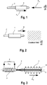
- Fig. 1 shows in a strongly simplified way a biomedical specimen in the form of an electrically conductive structure such as a stent 1 that is located on a carrier 2 that may e.g. be a balloon catheter.
- An external alternating magnetic field dB/dt is created near or around the specimen 1 that creates a magnetic force F M counteracting a retention force F R that is e.g. a frictional force that holds the specimen 1 on the carrier 2.
- Fig. 2 shows a similar embodiment of a specimen 1 on a carrier 2 that, however, is moved in the direction of the arrow M into a magnetic field dB/dt that is a magnetic field having a spatial gradient.
- Fig. 3 depicts a third possible embodiment of the present invention that corresponds to test setup 2 explained hereinbefore.
- this embodiment comprises again a carrier 2 that is surrounded by a primary coil 3 being connected to a voltage supply 4.
- an arrangement of a shaft 5, a catheter 6 as well as a stent 7 is disposed on carrier 2 so that this arrangement is comparable to a transformer having a primary coil 3 and stent 7 as a secondary coil.
Landscapes
- Engineering & Computer Science (AREA)
- Automation & Control Theory (AREA)
- Physics & Mathematics (AREA)
- Health & Medical Sciences (AREA)
- Life Sciences & Earth Sciences (AREA)
- Chemical & Material Sciences (AREA)
- Analytical Chemistry (AREA)
- Biochemistry (AREA)
- General Health & Medical Sciences (AREA)
- General Physics & Mathematics (AREA)
- Immunology (AREA)
- Pathology (AREA)
- Investigating Or Analyzing Materials By The Use Of Magnetic Means (AREA)
Claims (4)
- Verfahren zum Messen der Haltekraft (FR) einer biomedizinischen Probe (1) in der Form einer elektrisch leitfähigen Anordnung, die auf einem Träger (2) angeordnet ist, das die folgenden Verfahrensschritte aufweist:- Erzeugen eines äußeren magnetischen Wechselfeldes dB/dt oder dB/dx in der Nähe der Probe (1);- Erhöhen der Amplitude und/oder Frequenz des Magnetfeldes;- Erfassen des Beginns einer Bewegung der Probe (1) auf dem Träger (2); und- Berechnen der Haltekraft (FR) durch Bestimmen der aufgebrachten Magnetkraft (FM) auf der Basis der Parameter des jeweiligen Magnetfeldes.
- Verfahren gemäß Anspruch 1, das die folgenden Schritte aufweist:- Anordnen einer Primärspule (3) auf dem Träger (2);- Anordnen der Probe (7) auf demselben Träger (2), wodurch eine transformatorähnliche Anordnung erzeugt wird;- Erzeugen des äußeren magnetischen Wechselfeldes in der Primärspule (3), wodurch eine Magnetkraft (FM) auf die Probe (7) durch magnetische Induktion aufgebracht wird.
- Verfahren gemäß Anspruch 1, das durch Bewegen der Probe (1;7) und des Trägers (2) relativ zum Magnetfeld (dB/dx), das einen räumlichen Gradienten aufweist, gekennzeichnet ist.
- Verfahren gemäß Anspruch 1, gekennzeichnet durch Verwendung von Permanentmagneten, um das räumlich variierende Magnetfeld (dB/dx) zu erzeugen.
Priority Applications (2)
| Application Number | Priority Date | Filing Date | Title |
|---|---|---|---|
| EP06019385.1A EP1901055B1 (de) | 2006-09-15 | 2006-09-15 | Verfahren zur Haltekraftmessung eines Implantats |
| US11/856,008 US7730788B2 (en) | 2006-09-15 | 2007-09-14 | Method of measuring the retention force of a biomedical specimen in the form of an electrically conductive structure located on a carrier |
Applications Claiming Priority (1)
| Application Number | Priority Date | Filing Date | Title |
|---|---|---|---|
| EP06019385.1A EP1901055B1 (de) | 2006-09-15 | 2006-09-15 | Verfahren zur Haltekraftmessung eines Implantats |
Publications (2)
| Publication Number | Publication Date |
|---|---|
| EP1901055A1 EP1901055A1 (de) | 2008-03-19 |
| EP1901055B1 true EP1901055B1 (de) | 2017-10-18 |
Family
ID=37728420
Family Applications (1)
| Application Number | Title | Priority Date | Filing Date |
|---|---|---|---|
| EP06019385.1A Not-in-force EP1901055B1 (de) | 2006-09-15 | 2006-09-15 | Verfahren zur Haltekraftmessung eines Implantats |
Country Status (2)
| Country | Link |
|---|---|
| US (1) | US7730788B2 (de) |
| EP (1) | EP1901055B1 (de) |
Families Citing this family (1)
| Publication number | Priority date | Publication date | Assignee | Title |
|---|---|---|---|---|
| CN114509710A (zh) * | 2022-01-25 | 2022-05-17 | 上海卫星工程研究所 | 非接触磁浮机构输出力测试设备及方法 |
Family Cites Families (9)
| Publication number | Priority date | Publication date | Assignee | Title |
|---|---|---|---|---|
| US4017192A (en) * | 1975-02-06 | 1977-04-12 | Neotec Corporation | Optical analysis of biomedical specimens |
| US3927724A (en) * | 1975-02-26 | 1975-12-23 | Royal Industries | Load cell retaining apparatus for on-board vehicle weighing systems |
| DE3507002A1 (de) * | 1984-02-29 | 1985-08-29 | Australian Biomedical Corp. Ltd., Canberra | Streckschiene |
| IL119189A0 (en) | 1996-09-03 | 1996-12-05 | Lev Shlomo | Annulus catheter |
| DE19803219A1 (de) * | 1998-01-28 | 1999-08-12 | Fraunhofer Ges Forschung | Verfahren und Vorrichtung zur Bestimmung des Oberflächen-Reibungskoeffizienten von Körpern |
| US6673102B1 (en) | 1999-01-22 | 2004-01-06 | Gore Enterprises Holdings, Inc. | Covered endoprosthesis and delivery system |
| US6682553B1 (en) | 2000-12-28 | 2004-01-27 | Advanced Cardiovascular Systems, Inc. | System and method for stent retention |
| KR100414353B1 (ko) * | 2001-06-30 | 2004-01-07 | 한국과학기술연구원 | 평판시편을 마찰 및 마멸하기 위한 미세 실험장치 |
| JP2004177332A (ja) * | 2002-11-28 | 2004-06-24 | Fuji Photo Film Co Ltd | 摩擦係数測定方法及び摩擦係数測定装置 |
-
2006
- 2006-09-15 EP EP06019385.1A patent/EP1901055B1/de not_active Not-in-force
-
2007
- 2007-09-14 US US11/856,008 patent/US7730788B2/en not_active Expired - Fee Related
Non-Patent Citations (1)
| Title |
|---|
| None * |
Also Published As
| Publication number | Publication date |
|---|---|
| EP1901055A1 (de) | 2008-03-19 |
| US20080134799A1 (en) | 2008-06-12 |
| US7730788B2 (en) | 2010-06-08 |
Similar Documents
| Publication | Publication Date | Title |
|---|---|---|
| Kollmannsberger et al. | BaHigh-force magnetic tweezers with force feedback for biological applications | |
| Haber et al. | Magnetic tweezers for DNA micromanipulation | |
| US8044660B2 (en) | Arrangement and method for influencing and/or detecting magnetic particles in a region of action | |
| AU2003278903A8 (en) | Detecting molecular binding by monitoring feedback controlled cantilever deflections | |
| KR950012094A (ko) | 미소부 물성정보 측정장치 | |
| WO2014180703A1 (en) | Device for measuring and closed-loop control of a magnetic field generated by an electromagnet | |
| CN101626725B (zh) | 用于磁性粒子成像的设备、用于影响和/或检测多个和单个磁性粒子的方法 | |
| EP2819608A1 (de) | Magnetisches navigationssystem mit elektromagneten mit weichem magnetkern zum betrieb in einem nichtlinearen modus | |
| Chen et al. | Nonlinear control of an electromagnetic polymer MEMS hard-magnetic micromirror and its imaging application | |
| US7187166B2 (en) | Electrical property evaluation apparatus | |
| EP1901055A1 (de) | Verfahren zur Haltekraftmessung eines Implantats | |
| EP1395763B1 (de) | Veränderliche elektromagnetische dämpfungseinrichtung | |
| AU2002318340A1 (en) | Variable electromagnetic damping apparatus | |
| GB2569442A (en) | Materials testing apparatus | |
| US6844721B2 (en) | Variable electromagnetic damping apparatus | |
| WO2008142136A2 (en) | Discriminating magnetic material properties | |
| JP2007085815A (ja) | 微小押し込み試験装置 | |
| JP2012165537A (ja) | 磁気回路、及びアクチュエータ | |
| Poletkin et al. | Hybrid electromagnetic and electrostatic micromachined suspension with adjustable dynamics | |
| KR102501153B1 (ko) | 자기 증분 투자율을 이용한 금속 3d 프린팅 부재 항복강도 계측 방법 및 이를 위한 계측 시스템 | |
| Moorthy | Distortion Analysis of Magnetic Excitation–Inherent reflection of properties of ferromagnetic materials | |
| JPH05121228A (ja) | 電磁石装置 | |
| Bayliss et al. | Development of an electromagnetic spring for use with a high accuracy surface texture measuring probe. | |
| Nagata et al. | Numerical simulations and experiments of eddy current tests under various excitation methods | |
| Tan et al. | Damping estimation and control of a contactless brake system using an eddy current |
Legal Events
| Date | Code | Title | Description |
|---|---|---|---|
| PUAI | Public reference made under article 153(3) epc to a published international application that has entered the european phase |
Free format text: ORIGINAL CODE: 0009012 |
|
| AK | Designated contracting states |
Kind code of ref document: A1 Designated state(s): AT BE BG CH CY CZ DE DK EE ES FI FR GB GR HU IE IS IT LI LT LU LV MC NL PL PT RO SE SI SK TR |
|
| AX | Request for extension of the european patent |
Extension state: AL BA HR MK YU |
|
| 17P | Request for examination filed |
Effective date: 20080602 |
|
| 17Q | First examination report despatched |
Effective date: 20080707 |
|
| AKX | Designation fees paid |
Designated state(s): AT BE BG CH CY CZ DE DK EE ES FI FR GB GR HU IE IS IT LI LT LU LV MC NL PL PT RO SE SI SK TR |
|
| GRAP | Despatch of communication of intention to grant a patent |
Free format text: ORIGINAL CODE: EPIDOSNIGR1 |
|
| INTG | Intention to grant announced |
Effective date: 20170403 |
|
| GRAS | Grant fee paid |
Free format text: ORIGINAL CODE: EPIDOSNIGR3 |
|
| GRAA | (expected) grant |
Free format text: ORIGINAL CODE: 0009210 |
|
| AK | Designated contracting states |
Kind code of ref document: B1 Designated state(s): AT BE BG CH CY CZ DE DK EE ES FI FR GB GR HU IE IS IT LI LT LU LV MC NL PL PT RO SE SI SK TR |
|
| REG | Reference to a national code |
Ref country code: GB Ref legal event code: FG4D |
|
| REG | Reference to a national code |
Ref country code: CH Ref legal event code: EP |
|
| REG | Reference to a national code |
Ref country code: AT Ref legal event code: REF Ref document number: 938378 Country of ref document: AT Kind code of ref document: T Effective date: 20171115 Ref country code: IE Ref legal event code: FG4D |
|
| REG | Reference to a national code |
Ref country code: DE Ref legal event code: R096 Ref document number: 602006053869 Country of ref document: DE |
|
| REG | Reference to a national code |
Ref country code: NL Ref legal event code: MP Effective date: 20171018 |
|
| REG | Reference to a national code |
Ref country code: LT Ref legal event code: MG4D |
|
| REG | Reference to a national code |
Ref country code: AT Ref legal event code: MK05 Ref document number: 938378 Country of ref document: AT Kind code of ref document: T Effective date: 20171018 |
|
| PG25 | Lapsed in a contracting state [announced via postgrant information from national office to epo] |
Ref country code: NL Free format text: LAPSE BECAUSE OF FAILURE TO SUBMIT A TRANSLATION OF THE DESCRIPTION OR TO PAY THE FEE WITHIN THE PRESCRIBED TIME-LIMIT Effective date: 20171018 |
|
| PG25 | Lapsed in a contracting state [announced via postgrant information from national office to epo] |
Ref country code: LT Free format text: LAPSE BECAUSE OF FAILURE TO SUBMIT A TRANSLATION OF THE DESCRIPTION OR TO PAY THE FEE WITHIN THE PRESCRIBED TIME-LIMIT Effective date: 20171018 Ref country code: SE Free format text: LAPSE BECAUSE OF FAILURE TO SUBMIT A TRANSLATION OF THE DESCRIPTION OR TO PAY THE FEE WITHIN THE PRESCRIBED TIME-LIMIT Effective date: 20171018 Ref country code: ES Free format text: LAPSE BECAUSE OF FAILURE TO SUBMIT A TRANSLATION OF THE DESCRIPTION OR TO PAY THE FEE WITHIN THE PRESCRIBED TIME-LIMIT Effective date: 20171018 Ref country code: FI Free format text: LAPSE BECAUSE OF FAILURE TO SUBMIT A TRANSLATION OF THE DESCRIPTION OR TO PAY THE FEE WITHIN THE PRESCRIBED TIME-LIMIT Effective date: 20171018 |
|
| PG25 | Lapsed in a contracting state [announced via postgrant information from national office to epo] |
Ref country code: GR Free format text: LAPSE BECAUSE OF FAILURE TO SUBMIT A TRANSLATION OF THE DESCRIPTION OR TO PAY THE FEE WITHIN THE PRESCRIBED TIME-LIMIT Effective date: 20180119 Ref country code: IS Free format text: LAPSE BECAUSE OF FAILURE TO SUBMIT A TRANSLATION OF THE DESCRIPTION OR TO PAY THE FEE WITHIN THE PRESCRIBED TIME-LIMIT Effective date: 20180218 Ref country code: AT Free format text: LAPSE BECAUSE OF FAILURE TO SUBMIT A TRANSLATION OF THE DESCRIPTION OR TO PAY THE FEE WITHIN THE PRESCRIBED TIME-LIMIT Effective date: 20171018 Ref country code: BG Free format text: LAPSE BECAUSE OF FAILURE TO SUBMIT A TRANSLATION OF THE DESCRIPTION OR TO PAY THE FEE WITHIN THE PRESCRIBED TIME-LIMIT Effective date: 20180118 Ref country code: LV Free format text: LAPSE BECAUSE OF FAILURE TO SUBMIT A TRANSLATION OF THE DESCRIPTION OR TO PAY THE FEE WITHIN THE PRESCRIBED TIME-LIMIT Effective date: 20171018 |
|
| REG | Reference to a national code |
Ref country code: DE Ref legal event code: R097 Ref document number: 602006053869 Country of ref document: DE |
|
| PG25 | Lapsed in a contracting state [announced via postgrant information from national office to epo] |
Ref country code: SK Free format text: LAPSE BECAUSE OF FAILURE TO SUBMIT A TRANSLATION OF THE DESCRIPTION OR TO PAY THE FEE WITHIN THE PRESCRIBED TIME-LIMIT Effective date: 20171018 Ref country code: EE Free format text: LAPSE BECAUSE OF FAILURE TO SUBMIT A TRANSLATION OF THE DESCRIPTION OR TO PAY THE FEE WITHIN THE PRESCRIBED TIME-LIMIT Effective date: 20171018 Ref country code: DK Free format text: LAPSE BECAUSE OF FAILURE TO SUBMIT A TRANSLATION OF THE DESCRIPTION OR TO PAY THE FEE WITHIN THE PRESCRIBED TIME-LIMIT Effective date: 20171018 Ref country code: CZ Free format text: LAPSE BECAUSE OF FAILURE TO SUBMIT A TRANSLATION OF THE DESCRIPTION OR TO PAY THE FEE WITHIN THE PRESCRIBED TIME-LIMIT Effective date: 20171018 |
|
| PLBE | No opposition filed within time limit |
Free format text: ORIGINAL CODE: 0009261 |
|
| STAA | Information on the status of an ep patent application or granted ep patent |
Free format text: STATUS: NO OPPOSITION FILED WITHIN TIME LIMIT |
|
| PG25 | Lapsed in a contracting state [announced via postgrant information from national office to epo] |
Ref country code: IT Free format text: LAPSE BECAUSE OF FAILURE TO SUBMIT A TRANSLATION OF THE DESCRIPTION OR TO PAY THE FEE WITHIN THE PRESCRIBED TIME-LIMIT Effective date: 20171018 Ref country code: PL Free format text: LAPSE BECAUSE OF FAILURE TO SUBMIT A TRANSLATION OF THE DESCRIPTION OR TO PAY THE FEE WITHIN THE PRESCRIBED TIME-LIMIT Effective date: 20171018 Ref country code: RO Free format text: LAPSE BECAUSE OF FAILURE TO SUBMIT A TRANSLATION OF THE DESCRIPTION OR TO PAY THE FEE WITHIN THE PRESCRIBED TIME-LIMIT Effective date: 20171018 |
|
| 26N | No opposition filed |
Effective date: 20180719 |
|
| PG25 | Lapsed in a contracting state [announced via postgrant information from national office to epo] |
Ref country code: SI Free format text: LAPSE BECAUSE OF FAILURE TO SUBMIT A TRANSLATION OF THE DESCRIPTION OR TO PAY THE FEE WITHIN THE PRESCRIBED TIME-LIMIT Effective date: 20171018 |
|
| PG25 | Lapsed in a contracting state [announced via postgrant information from national office to epo] |
Ref country code: MC Free format text: LAPSE BECAUSE OF FAILURE TO SUBMIT A TRANSLATION OF THE DESCRIPTION OR TO PAY THE FEE WITHIN THE PRESCRIBED TIME-LIMIT Effective date: 20171018 |
|
| REG | Reference to a national code |
Ref country code: CH Ref legal event code: PL |
|
| GBPC | Gb: european patent ceased through non-payment of renewal fee |
Effective date: 20180915 |
|
| REG | Reference to a national code |
Ref country code: BE Ref legal event code: MM Effective date: 20180930 |
|
| PG25 | Lapsed in a contracting state [announced via postgrant information from national office to epo] |
Ref country code: LU Free format text: LAPSE BECAUSE OF NON-PAYMENT OF DUE FEES Effective date: 20180915 |
|
| PG25 | Lapsed in a contracting state [announced via postgrant information from national office to epo] |
Ref country code: LI Free format text: LAPSE BECAUSE OF NON-PAYMENT OF DUE FEES Effective date: 20180930 Ref country code: FR Free format text: LAPSE BECAUSE OF NON-PAYMENT OF DUE FEES Effective date: 20180930 Ref country code: CH Free format text: LAPSE BECAUSE OF NON-PAYMENT OF DUE FEES Effective date: 20180930 Ref country code: BE Free format text: LAPSE BECAUSE OF NON-PAYMENT OF DUE FEES Effective date: 20180930 |
|
| PG25 | Lapsed in a contracting state [announced via postgrant information from national office to epo] |
Ref country code: GB Free format text: LAPSE BECAUSE OF NON-PAYMENT OF DUE FEES Effective date: 20180915 |
|
| PGFP | Annual fee paid to national office [announced via postgrant information from national office to epo] |
Ref country code: IE Payment date: 20190826 Year of fee payment: 14 |
|
| PG25 | Lapsed in a contracting state [announced via postgrant information from national office to epo] |
Ref country code: TR Free format text: LAPSE BECAUSE OF FAILURE TO SUBMIT A TRANSLATION OF THE DESCRIPTION OR TO PAY THE FEE WITHIN THE PRESCRIBED TIME-LIMIT Effective date: 20171018 |
|
| PG25 | Lapsed in a contracting state [announced via postgrant information from national office to epo] |
Ref country code: HU Free format text: LAPSE BECAUSE OF FAILURE TO SUBMIT A TRANSLATION OF THE DESCRIPTION OR TO PAY THE FEE WITHIN THE PRESCRIBED TIME-LIMIT; INVALID AB INITIO Effective date: 20060915 Ref country code: PT Free format text: LAPSE BECAUSE OF FAILURE TO SUBMIT A TRANSLATION OF THE DESCRIPTION OR TO PAY THE FEE WITHIN THE PRESCRIBED TIME-LIMIT Effective date: 20171018 |
|
| PG25 | Lapsed in a contracting state [announced via postgrant information from national office to epo] |
Ref country code: CY Free format text: LAPSE BECAUSE OF FAILURE TO SUBMIT A TRANSLATION OF THE DESCRIPTION OR TO PAY THE FEE WITHIN THE PRESCRIBED TIME-LIMIT Effective date: 20171018 |
|
| PGFP | Annual fee paid to national office [announced via postgrant information from national office to epo] |
Ref country code: DE Payment date: 20200812 Year of fee payment: 15 |
|
| PG25 | Lapsed in a contracting state [announced via postgrant information from national office to epo] |
Ref country code: IE Free format text: LAPSE BECAUSE OF NON-PAYMENT OF DUE FEES Effective date: 20200915 |
|
| REG | Reference to a national code |
Ref country code: DE Ref legal event code: R119 Ref document number: 602006053869 Country of ref document: DE |
|
| PG25 | Lapsed in a contracting state [announced via postgrant information from national office to epo] |
Ref country code: DE Free format text: LAPSE BECAUSE OF NON-PAYMENT OF DUE FEES Effective date: 20220401 |