EP1900985B1 - Dispositif de réglage et d'étranglement de débit d'un fluide - Google Patents
Dispositif de réglage et d'étranglement de débit d'un fluide Download PDFInfo
- Publication number
- EP1900985B1 EP1900985B1 EP20060425642 EP06425642A EP1900985B1 EP 1900985 B1 EP1900985 B1 EP 1900985B1 EP 20060425642 EP20060425642 EP 20060425642 EP 06425642 A EP06425642 A EP 06425642A EP 1900985 B1 EP1900985 B1 EP 1900985B1
- Authority
- EP
- European Patent Office
- Prior art keywords
- fluid
- control element
- flow control
- rotating body
- pressure
- Prior art date
- Legal status (The legal status is an assumption and is not a legal conclusion. Google has not performed a legal analysis and makes no representation as to the accuracy of the status listed.)
- Not-in-force
Links
Images


Classifications
-
- F—MECHANICAL ENGINEERING; LIGHTING; HEATING; WEAPONS; BLASTING
- F16—ENGINEERING ELEMENTS AND UNITS; GENERAL MEASURES FOR PRODUCING AND MAINTAINING EFFECTIVE FUNCTIONING OF MACHINES OR INSTALLATIONS; THERMAL INSULATION IN GENERAL
- F16K—VALVES; TAPS; COCKS; ACTUATING-FLOATS; DEVICES FOR VENTING OR AERATING
- F16K1/00—Lift valves or globe valves, i.e. cut-off apparatus with closure members having at least a component of their opening and closing motion perpendicular to the closing faces
- F16K1/32—Details
- F16K1/52—Means for additional adjustment of the rate of flow
- F16K1/526—Means for additional adjustment of the rate of flow for limiting the maximum flow rate, using a second valve
-
- F—MECHANICAL ENGINEERING; LIGHTING; HEATING; WEAPONS; BLASTING
- F16—ENGINEERING ELEMENTS AND UNITS; GENERAL MEASURES FOR PRODUCING AND MAINTAINING EFFECTIVE FUNCTIONING OF MACHINES OR INSTALLATIONS; THERMAL INSULATION IN GENERAL
- F16K—VALVES; TAPS; COCKS; ACTUATING-FLOATS; DEVICES FOR VENTING OR AERATING
- F16K31/00—Actuating devices; Operating means; Releasing devices
- F16K31/44—Mechanical actuating means
- F16K31/60—Handles
-
- F—MECHANICAL ENGINEERING; LIGHTING; HEATING; WEAPONS; BLASTING
- F16—ENGINEERING ELEMENTS AND UNITS; GENERAL MEASURES FOR PRODUCING AND MAINTAINING EFFECTIVE FUNCTIONING OF MACHINES OR INSTALLATIONS; THERMAL INSULATION IN GENERAL
- F16K—VALVES; TAPS; COCKS; ACTUATING-FLOATS; DEVICES FOR VENTING OR AERATING
- F16K37/00—Special means in or on valves or other cut-off apparatus for indicating or recording operation thereof, or for enabling an alarm to be given
- F16K37/0008—Mechanical means
-
- Y—GENERAL TAGGING OF NEW TECHNOLOGICAL DEVELOPMENTS; GENERAL TAGGING OF CROSS-SECTIONAL TECHNOLOGIES SPANNING OVER SEVERAL SECTIONS OF THE IPC; TECHNICAL SUBJECTS COVERED BY FORMER USPC CROSS-REFERENCE ART COLLECTIONS [XRACs] AND DIGESTS
- Y10—TECHNICAL SUBJECTS COVERED BY FORMER USPC
- Y10T—TECHNICAL SUBJECTS COVERED BY FORMER US CLASSIFICATION
- Y10T137/00—Fluid handling
- Y10T137/8158—With indicator, register, recorder, alarm or inspection means
- Y10T137/8359—Inspection means
-
- Y—GENERAL TAGGING OF NEW TECHNOLOGICAL DEVELOPMENTS; GENERAL TAGGING OF CROSS-SECTIONAL TECHNOLOGIES SPANNING OVER SEVERAL SECTIONS OF THE IPC; TECHNICAL SUBJECTS COVERED BY FORMER USPC CROSS-REFERENCE ART COLLECTIONS [XRACs] AND DIGESTS
- Y10—TECHNICAL SUBJECTS COVERED BY FORMER USPC
- Y10T—TECHNICAL SUBJECTS COVERED BY FORMER US CLASSIFICATION
- Y10T137/00—Fluid handling
- Y10T137/8593—Systems
- Y10T137/877—With flow control means for branched passages
- Y10T137/87829—Biased valve
- Y10T137/87837—Spring bias
- Y10T137/87861—Spring coaxial with valve
-
- Y—GENERAL TAGGING OF NEW TECHNOLOGICAL DEVELOPMENTS; GENERAL TAGGING OF CROSS-SECTIONAL TECHNOLOGIES SPANNING OVER SEVERAL SECTIONS OF THE IPC; TECHNICAL SUBJECTS COVERED BY FORMER USPC CROSS-REFERENCE ART COLLECTIONS [XRACs] AND DIGESTS
- Y10—TECHNICAL SUBJECTS COVERED BY FORMER USPC
- Y10T—TECHNICAL SUBJECTS COVERED BY FORMER US CLASSIFICATION
- Y10T137/00—Fluid handling
- Y10T137/8593—Systems
- Y10T137/877—With flow control means for branched passages
- Y10T137/87909—Containing rotary valve
Definitions
- the present invention relates to a device for adjusting and throttling the flow-rate of a fluid, particularly medical oxygen and compressed gases in general.
- Such devices are generally arranged downstream of a pressure reduction unit, which must be provided with a means for throttling the high-pressure flow of fluid.
- US 6962167 discloses a device according to the preamble of independent claim 1.
- Another problem further consists in that the disks with calibrated holes, which typically rotate with respect to the port that controls the flow of the low-pressure fluid, can be subject to deformations, since in order to try to optimize the precision of the holes it is necessary to use relatively low thicknesses.
- Another problem further consists in that in the solutions of the background art, when changing the flow-rate, the output port for the passage of the fluid may accidentally arrange itself in a region which does not allow the passage of the fluid, with consequent severe risks for the patient.
- the aim of the invention is to eliminate the drawbacks described above by providing a device for adjusting and throttling the flow-rate of a fluid, particularly medical oxygen, which allows to incorporate therein two separate functions, simplifying both the structure and the actuation of the device.
- a particular object of the invention is to provide a device in which there is always the absolute certainty of not arranging the actuation handwheel in regions where the flow of the fluid accidentally does not occur, thus contributing to greater safety of the assembly.
- Another object of the present invention is to provide a device which thanks to its particular constructive characteristics is capable of giving the greatest assurances of reliability and safety in use.
- Still another object of the present invention is to provide a device for adjusting and throttling the flow-rate of a fluid, particularly medical oxygen, which can be obtained easily starting from commonly commercially available elements and materials and is also competitive from a merely economical standpoint.
- a device for adjusting and throttling the flow-rate of a fluid, particularly medical oxygen characterized in that it comprises a valve body which defines an input port and an output port for a fluid at high pressure, said input port being controlled by a high-pressure flow control element, an input duct for a low-pressure fluid being further provided which is connected to a rotating body with a control port which can be arranged at the calibrated holes provided in an adjustment disk and connected to at least one output duct, a single actuation handwheel being further provided which drives said high-pressure flow control element and said rotating body.
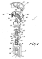
- the device for adjusting and throttling the flow-rate of a fluid, particularly medical oxygen comprises a valve body 2 which defines in a downward region a port 3 for the inflow of a pressurized fluid, which is flanked by a port 4 for the outflow of the pressurized fluid.
- the port 3 is controlled by a high-pressure flow control element 5, provided with a sealing gasket 6 which can be arranged hermetically on the high-pressure input port 3.
- the high-pressure fluid enters the port 3 and, if the gasket 6 is in a spaced position, is sent to the pressure reduction unit by way of the high-pressure output port 4; from the pressure reduction unit, the fluid is fed into an input duct 8 defined in the valve body 2; the low-pressure fluid, by way of a connecting body 9, is introduced in a manifold 10 which is provided in the body 9 and has a circular shape.
- a fixed disk 11, with calibrated holes 12 arranged correspondingly with respect to the circular manifold 10, is positioned above the connecting body 9; the disk 11 has a low thickness of less than one tenth of a millimeter.
- a rotating body 15 acts on the disk 11 and is provided with a control port 16 equipped with an O-ring gasket 16a, which is arranged at the region affected by the calibrated holes and is connected to an internal output duct 17, which, by passing through the flow control element 5, connects to the output duct 18.
- the calibrated disk 11 is kept in position by means of a spacer 20, which is clamped by means of a cap 21 on which a compression spring 22 acts which pushes, so as to form a seal, the face of the rotating body which engages the disk 11 with calibrated holes 12.
- Gaskets which are similar to the ones that affect the port 16 and merely have a balancing function can be arranged symmetrically on the rotating body.
- the rotating body defines a shank 25, which engages polygonally an axial cavity 26 provided in the flow control element 5 which is provided with a male thread 27 which engages a corresponding female thread 28 defined by the valve body in order to produce the translational motion of the flow control element 5 when the rotating body turns.
- the rotating body rigidly rotationally engages a shaft 30 provided with a lower flange 31, which arranges itself below the cap 21 and defines an upper engagement element or contoured portion 32 for engagement with an actuation handwheel, generally designated by the reference numeral 35.
- the actuation handwheel 35 has the important function of actuating both the high-pressure flow control element 5 and the rotating flow-rate adjustment body.
- the actuation handwheel 35 is provided by means of a lower portion 40, which is fixed with respect to the valve body in order to engage an internal set of teeth thereof with an external set of teeth provided on the cap so as to prevent relative rotation.
- the lower portion 40 defines an outer border 41 with a window 42 for viewing an indication related to the flow-rate which is located, as will become better apparent hereinafter, on the upper portion of the actuation handwheel.
- the lower portion 40 has an internal flange 39 which allows the passage of the shaft 30 with the possibility of rotation.
- a portion of a front set of teeth 43 is provided on the upper face of the flange 39 and affects only a portion of the circumferential extension so as to leave a free region 44 on the flange 39.
- An upper portion 50 engages the lower portion 40 and forms a cylindrical side wall 51, which enters the outer border 41 and bears indications 52 related to the flow-rate which are visible on the side wall.
- an upper window 54 is provided in the upper frustum-shaped portion 53 of the upper portion 50, and flow-rate indications 55 provided on the upper inclined portion 47 of the lower portion 40 can be viewed through said window.
- the upper part 50 has a contoured hole 51 which engages the contoured portion 32 of the shaft 30, so that the upper portion rotates rigidly with the shaft 30 but can perform an axial translational motion.
- the coupling of the actuation handwheel is achieved by means of a ring 60, which screws onto the upper end of the shaft 30 and acts on the end of a pusher spring 61 which acts on the upper portion 50 of the handwheel in order to push it against the lower portion of said handwheel.
- the upper portion 50 has front teeth 57 which engage the front set of teeth 43 so as to always define stable positions in which the port 16 is located at a calibrated hole in order to prevent the accidental interruption of the flow.
- the high-pressure flow control element 5 is actuated, allowing its opening or closure.
- the invention achieves the intended aim and objects, and in particular the fact is stressed that a device is provided in which the actuation handwheel, in a first portion of rotation, allows to act on the high-pressure flow control (throttling) element, and, by continuing the rotation, when the sets of teeth engage, the stable positions that correspond to the different flow-rates are achieved.
- Another important aspect further consists in that the flow-rates can be viewed both on the outer border and in an upward region, thus allowing optimum viewing of the flow-rate.
- the materials used, as well as the contingent shapes and dimensions may be any according to requirements.
Claims (14)
- Dispositif pour régler et étrangler le débit d'un fluide, en particulier de l'oxygène médical et de façon générale des gaz comprimés, le dispositif comprenant un corps (2) de vanne qui définit un orifice d'entrée (3) et un orifice de sortie (4) pour un fluide à haute pression, ledit orifice d'entrée (3) étant commandé par un élément de régulation (5) de flux à haute pression, un conduit d'entrée (8) pour un fluide à basse pression étant en outre présent et relié à un corps tournant (15) à orifice de commande (16) qui est disposé au niveau de trous étalonnés (12) ménagés dans un disque de réglage (11) et est relié à au moins un conduit de sortie, caractérisé en ce qu'un unique volant de manoeuvre (35) est présent et entraîne ledit élément de régulation (5) de flux à haute pression et ledit corps tournant (15).
- Dispositif selon la revendication 1, caractérisé en ce que ledit disque de réglage (11) a une position fixe.
- Dispositif selon l'une et/ou l'autre des revendications précédentes, caractérisé en ce que ledit disque de réglage (11) a une épaisseur inférieure à un dixième de millimètre.
- Dispositif selon une ou plusieurs des revendications précédentes, caractérisé en ce qu'il comprend une entretoise (20) pour fixer ledit disque de réglage (11), qui peut se mettre en place à l'aide d'un couvercle (21) pouvant se monter sur ledit corps de vanne.
- Dispositif selon une ou plusieurs des revendications précédentes, caractérisé en ce qu'il comprend un ressort de compression (22) qui agit entre ledit couvercle (21) et ledit corps tournant (15) disposé sur ledit disque de réglage (11).
- Dispositif selon une ou plusieurs des revendications précédentes, caractérisé en ce que ledit corps tournant (15) a une tige (25) pouvant coopérer solidairement en rotation, tout en pouvant coulisser axialement, avec une capité axiale (26) définie par ledit élément de régulation de flux.
- Dispositif selon une ou plusieurs des revendications précédentes, caractérisé en ce que ledit élément de régulation de flux à basse pression comporte un filetage mâle (27) apte à s'engager dans un filetage femelle correspondant (28) défini par ledit corps de vanne pour le mouvement de translation dudit élément de régulation (5) de flux à haute pression.
- Dispositif selon la revendication 4, caractérisé en ce qu'il comprend un arbre (30) qui est muni d'une collerette inférieure (31) destinée à venir au contact dudit couvercle et qui coopère solidairement en rotation avec ledit corps tournant, ledit arbre coopérant solidairement en rotation avec ledit volant de manoeuvre.
- Dispositif selon une ou plusieurs des revendications précédentes, caractérisé en ce que ledit volant de manoeuvre (35) comporte une partie inférieure (40) fixée sur ledit corps de vanne, et une partie supérieure (50) qui tourne solidairement dudit corps tournant (15) et vient contre ladite partie inférieure en ayant la possibilité de coulisser axialement et de tourner.
- Dispositif selon les revendications 8 et 9, caractérisé en ce qu'il comprend une bague montée sur ledit arbre (30) et agissant, par l'intermédiaire d'un ressort de poussée, sur ladite partie supérieure (50) dudit volant afin de la pousser contre ladite partie inférieure.
- Dispositif selon la revendication 9 ou 10, caractérisé en ce que ladite partie supérieure (50) a un ensemble frontal de dents (57) qui n'affecte qu'une partie périphérique et peut coopérer avec des dents avant (43) afin de définir des positions stables dans la partie destinée à s'engager entre lesdites dents avant et ladite partie de l'ensemble frontal de dents.
- Dispositif selon la revendication 11, caractérisé en ce que lesdites dents avant (57) coopèrent avec la région libre qui est latéralement adjacente à ladite partie de l'ensemble frontal de dents pendant la partie de la rotation dudit volant de manoeuvre servant à ouvrir et fermer ledit élément de régulation de flux haute pression.
- Dispositif selon une ou plusieurs des revendications 9 à 12, caractérisé en ce que ladite partie inférieure fixe définit un bord extérieur avec une fenêtre pour consulter une indication relative au débit, qui se trouve sur une paroi latérale cylindrique de ladite partie supérieure (50).
- Dispositif selon une ou plusieurs des revendications 9 à 13, caractérise en ce que ladite partie supérieure mobile (50) est située dans une région haute à encoche supérieure au moyen de laquelle il est possible d'observer des indications de débit présentées d'une manière correspondant à la partie supérieure inclinée de ladite partie inférieure (40).
Priority Applications (6)
| Application Number | Priority Date | Filing Date | Title |
|---|---|---|---|
| ES06425642T ES2341569T3 (es) | 2006-09-18 | 2006-09-18 | Dispositivo para ajustar y estrangular la velocidad de flujo de un fluido. |
| AT06425642T ATE453075T1 (de) | 2006-09-18 | 2006-09-18 | Durchflussregel- und drosselvorrichtung für ein fluid |
| EP20060425642 EP1900985B1 (fr) | 2006-09-18 | 2006-09-18 | Dispositif de réglage et d'étranglement de débit d'un fluide |
| DE200660011321 DE602006011321D1 (de) | 2006-09-18 | 2006-09-18 | Durchflussregel- und Drosselvorrichtung für ein Fluid |
| US11/898,088 US7823606B2 (en) | 2006-09-18 | 2007-09-10 | Device for adjusting and throttling the flow-rate of a fluid, particularly medical oxygen and compressed gases in general |
| CA 2602270 CA2602270C (fr) | 2006-09-18 | 2007-09-12 | Dispositif pour regler et reguler par etranglement le debit d'un fluide, particulierement l'oxygene therapeutique et les gaz comprimes en general |
Applications Claiming Priority (1)
| Application Number | Priority Date | Filing Date | Title |
|---|---|---|---|
| EP20060425642 EP1900985B1 (fr) | 2006-09-18 | 2006-09-18 | Dispositif de réglage et d'étranglement de débit d'un fluide |
Publications (2)
| Publication Number | Publication Date |
|---|---|
| EP1900985A1 EP1900985A1 (fr) | 2008-03-19 |
| EP1900985B1 true EP1900985B1 (fr) | 2009-12-23 |
Family
ID=37684429
Family Applications (1)
| Application Number | Title | Priority Date | Filing Date |
|---|---|---|---|
| EP20060425642 Not-in-force EP1900985B1 (fr) | 2006-09-18 | 2006-09-18 | Dispositif de réglage et d'étranglement de débit d'un fluide |
Country Status (6)
| Country | Link |
|---|---|
| US (1) | US7823606B2 (fr) |
| EP (1) | EP1900985B1 (fr) |
| AT (1) | ATE453075T1 (fr) |
| CA (1) | CA2602270C (fr) |
| DE (1) | DE602006011321D1 (fr) |
| ES (1) | ES2341569T3 (fr) |
Families Citing this family (8)
| Publication number | Priority date | Publication date | Assignee | Title |
|---|---|---|---|---|
| WO2011011057A2 (fr) * | 2009-07-20 | 2011-01-27 | Duncan David R | Vanne de robinet d'arrêt à orifices multiples et système de définition d'écoulement |
| US9638331B2 (en) | 2013-07-19 | 2017-05-02 | Western Enterprises/Scott Fetzer Company | Fluid control assemblies and flow path inserts |
| USD735034S1 (en) | 2013-07-26 | 2015-07-28 | Western/Scott Fetzer Company | Gas container shroud |
| US9417148B2 (en) | 2013-07-26 | 2016-08-16 | Western/Scott Fetzer Company | Indicating assembly for a pressurized container |
| CN105570502B (zh) * | 2016-02-02 | 2017-12-26 | 南京航海仪器二厂有限公司 | 一种快速卸荷安全阀 |
| FR3064717A1 (fr) * | 2017-03-31 | 2018-10-05 | L'air Liquide, Societe Anonyme Pour L'etude Et L'exploitation Des Procedes Georges Claude | Dispositif de distribution de gaz a systeme de couplage ameliore de l’organe de manœuvre |
| CN211082858U (zh) * | 2019-11-19 | 2020-07-24 | 深圳市科曼医疗设备有限公司 | 比例阀及呼吸机 |
| USD986496S1 (en) * | 2020-09-24 | 2023-05-16 | Dustin Anthony | Smoking device |
Family Cites Families (5)
| Publication number | Priority date | Publication date | Assignee | Title |
|---|---|---|---|---|
| GB199915A (en) * | 1922-05-22 | 1923-07-05 | Walter Eraut | Improvements in screw-down stop valves and the like |
| US4643215A (en) * | 1985-07-19 | 1987-02-17 | Essex Industries, Inc. | Gas flow control valve |
| US5246201A (en) * | 1992-07-13 | 1993-09-21 | Regin Manufacturing, Inc. | Orifice assembly for gas metering device |
| US5640997A (en) * | 1994-08-05 | 1997-06-24 | B & F Medical Products, Inc. | Relief valve for gas flow rate regulator |
| ES2219592T3 (es) * | 2002-02-19 | 2004-12-01 | FESTO AG & CO | Valvula de estrangulamiento. |
-
2006
- 2006-09-18 EP EP20060425642 patent/EP1900985B1/fr not_active Not-in-force
- 2006-09-18 DE DE200660011321 patent/DE602006011321D1/de active Active
- 2006-09-18 AT AT06425642T patent/ATE453075T1/de active
- 2006-09-18 ES ES06425642T patent/ES2341569T3/es active Active
-
2007
- 2007-09-10 US US11/898,088 patent/US7823606B2/en not_active Expired - Fee Related
- 2007-09-12 CA CA 2602270 patent/CA2602270C/fr not_active Expired - Fee Related
Also Published As
| Publication number | Publication date |
|---|---|
| EP1900985A1 (fr) | 2008-03-19 |
| US20080066817A1 (en) | 2008-03-20 |
| CA2602270C (fr) | 2015-02-03 |
| DE602006011321D1 (de) | 2010-02-04 |
| US7823606B2 (en) | 2010-11-02 |
| CA2602270A1 (fr) | 2008-03-18 |
| ATE453075T1 (de) | 2010-01-15 |
| ES2341569T3 (es) | 2010-06-22 |
Similar Documents
| Publication | Publication Date | Title |
|---|---|---|
| EP1900985B1 (fr) | Dispositif de réglage et d'étranglement de débit d'un fluide | |
| EP1793299B1 (fr) | Régulateur de pression de gaz double pour un appareil électroménager | |
| EP1900986B1 (fr) | Dispositif de réglage de débit d'un fluide | |
| US7337805B2 (en) | Valve with adjustable stop | |
| KR101096832B1 (ko) | 유체 제어기 | |
| US11346553B2 (en) | Gas valve unit | |
| TWI783119B (zh) | 閥 | |
| US6009900A (en) | Gas fitting | |
| KR20140137298A (ko) | 유량 조절 장치 | |
| US20060185736A1 (en) | Two-stage pressure regulator for pressurized gas | |
| KR101907283B1 (ko) | 유체 제어기 | |
| EP3864338B1 (fr) | Réducteur de pression de gaz avec soupape d'arrêt commandée par came | |
| JP7478729B2 (ja) | 一体型遮断弁を有するガス減圧弁 | |
| JP2014105844A (ja) | 流量調整装置 | |
| JP2007139057A (ja) | 流量調整弁 | |
| KR20220045986A (ko) | 반경 방향으로 연장되는 작동 핸들을 갖는 가스 실린더 밸브 | |
| JP2013036560A (ja) | 圧力調整器 | |
| KR101934042B1 (ko) | 스윙타입 디스크를 구비한 글로브 밸브 | |
| JPH08159329A (ja) | ガス圧作動弁 | |
| WO2010124722A1 (fr) | Régulateur de pression | |
| JP2006519971A (ja) | 調節ストップをもつバルブ | |
| KR20020083486A (ko) | 소형 압력 조정기 |
Legal Events
| Date | Code | Title | Description |
|---|---|---|---|
| PUAI | Public reference made under article 153(3) epc to a published international application that has entered the european phase |
Free format text: ORIGINAL CODE: 0009012 |
|
| AK | Designated contracting states |
Kind code of ref document: A1 Designated state(s): AT BE BG CH CY CZ DE DK EE ES FI FR GB GR HU IE IS IT LI LT LU LV MC NL PL PT RO SE SI SK TR |
|
| AX | Request for extension of the european patent |
Extension state: AL BA HR MK YU |
|
| 17P | Request for examination filed |
Effective date: 20080905 |
|
| AKX | Designation fees paid |
Designated state(s): AT BE BG CH CY CZ DE DK EE ES FI FR GB GR HU IE IS IT LI LT LU LV MC NL PL PT RO SE SI SK TR |
|
| GRAP | Despatch of communication of intention to grant a patent |
Free format text: ORIGINAL CODE: EPIDOSNIGR1 |
|
| GRAS | Grant fee paid |
Free format text: ORIGINAL CODE: EPIDOSNIGR3 |
|
| GRAA | (expected) grant |
Free format text: ORIGINAL CODE: 0009210 |
|
| AK | Designated contracting states |
Kind code of ref document: B1 Designated state(s): AT BE BG CH CY CZ DE DK EE ES FI FR GB GR HU IE IS IT LI LT LU LV MC NL PL PT RO SE SI SK TR |
|
| REG | Reference to a national code |
Ref country code: GB Ref legal event code: FG4D |
|
| REG | Reference to a national code |
Ref country code: CH Ref legal event code: EP |
|
| REG | Reference to a national code |
Ref country code: IE Ref legal event code: FG4D |
|
| REF | Corresponds to: |
Ref document number: 602006011321 Country of ref document: DE Date of ref document: 20100204 Kind code of ref document: P |
|
| REG | Reference to a national code |
Ref country code: NL Ref legal event code: VDEP Effective date: 20091223 |
|
| PG25 | Lapsed in a contracting state [announced via postgrant information from national office to epo] |
Ref country code: SE Free format text: LAPSE BECAUSE OF FAILURE TO SUBMIT A TRANSLATION OF THE DESCRIPTION OR TO PAY THE FEE WITHIN THE PRESCRIBED TIME-LIMIT Effective date: 20091223 Ref country code: LT Free format text: LAPSE BECAUSE OF FAILURE TO SUBMIT A TRANSLATION OF THE DESCRIPTION OR TO PAY THE FEE WITHIN THE PRESCRIBED TIME-LIMIT Effective date: 20091223 Ref country code: FI Free format text: LAPSE BECAUSE OF FAILURE TO SUBMIT A TRANSLATION OF THE DESCRIPTION OR TO PAY THE FEE WITHIN THE PRESCRIBED TIME-LIMIT Effective date: 20091223 |
|
| LTIE | Lt: invalidation of european patent or patent extension |
Effective date: 20091223 |
|
| PG25 | Lapsed in a contracting state [announced via postgrant information from national office to epo] |
Ref country code: PL Free format text: LAPSE BECAUSE OF FAILURE TO SUBMIT A TRANSLATION OF THE DESCRIPTION OR TO PAY THE FEE WITHIN THE PRESCRIBED TIME-LIMIT Effective date: 20091223 Ref country code: LV Free format text: LAPSE BECAUSE OF FAILURE TO SUBMIT A TRANSLATION OF THE DESCRIPTION OR TO PAY THE FEE WITHIN THE PRESCRIBED TIME-LIMIT Effective date: 20091223 Ref country code: SI Free format text: LAPSE BECAUSE OF FAILURE TO SUBMIT A TRANSLATION OF THE DESCRIPTION OR TO PAY THE FEE WITHIN THE PRESCRIBED TIME-LIMIT Effective date: 20091223 |
|
| REG | Reference to a national code |
Ref country code: ES Ref legal event code: FG2A Ref document number: 2341569 Country of ref document: ES Kind code of ref document: T3 |
|
| PG25 | Lapsed in a contracting state [announced via postgrant information from national office to epo] |
Ref country code: RO Free format text: LAPSE BECAUSE OF FAILURE TO SUBMIT A TRANSLATION OF THE DESCRIPTION OR TO PAY THE FEE WITHIN THE PRESCRIBED TIME-LIMIT Effective date: 20091223 Ref country code: NL Free format text: LAPSE BECAUSE OF FAILURE TO SUBMIT A TRANSLATION OF THE DESCRIPTION OR TO PAY THE FEE WITHIN THE PRESCRIBED TIME-LIMIT Effective date: 20091223 Ref country code: EE Free format text: LAPSE BECAUSE OF FAILURE TO SUBMIT A TRANSLATION OF THE DESCRIPTION OR TO PAY THE FEE WITHIN THE PRESCRIBED TIME-LIMIT Effective date: 20091223 Ref country code: BG Free format text: LAPSE BECAUSE OF FAILURE TO SUBMIT A TRANSLATION OF THE DESCRIPTION OR TO PAY THE FEE WITHIN THE PRESCRIBED TIME-LIMIT Effective date: 20100323 Ref country code: IS Free format text: LAPSE BECAUSE OF FAILURE TO SUBMIT A TRANSLATION OF THE DESCRIPTION OR TO PAY THE FEE WITHIN THE PRESCRIBED TIME-LIMIT Effective date: 20100423 Ref country code: PT Free format text: LAPSE BECAUSE OF FAILURE TO SUBMIT A TRANSLATION OF THE DESCRIPTION OR TO PAY THE FEE WITHIN THE PRESCRIBED TIME-LIMIT Effective date: 20100423 |
|
| PG25 | Lapsed in a contracting state [announced via postgrant information from national office to epo] |
Ref country code: BE Free format text: LAPSE BECAUSE OF FAILURE TO SUBMIT A TRANSLATION OF THE DESCRIPTION OR TO PAY THE FEE WITHIN THE PRESCRIBED TIME-LIMIT Effective date: 20091223 Ref country code: SK Free format text: LAPSE BECAUSE OF FAILURE TO SUBMIT A TRANSLATION OF THE DESCRIPTION OR TO PAY THE FEE WITHIN THE PRESCRIBED TIME-LIMIT Effective date: 20091223 |
|
| PG25 | Lapsed in a contracting state [announced via postgrant information from national office to epo] |
Ref country code: CY Free format text: LAPSE BECAUSE OF FAILURE TO SUBMIT A TRANSLATION OF THE DESCRIPTION OR TO PAY THE FEE WITHIN THE PRESCRIBED TIME-LIMIT Effective date: 20091223 Ref country code: GR Free format text: LAPSE BECAUSE OF FAILURE TO SUBMIT A TRANSLATION OF THE DESCRIPTION OR TO PAY THE FEE WITHIN THE PRESCRIBED TIME-LIMIT Effective date: 20100324 |
|
| PLBE | No opposition filed within time limit |
Free format text: ORIGINAL CODE: 0009261 |
|
| STAA | Information on the status of an ep patent application or granted ep patent |
Free format text: STATUS: NO OPPOSITION FILED WITHIN TIME LIMIT |
|
| 26N | No opposition filed |
Effective date: 20100924 |
|
| PG25 | Lapsed in a contracting state [announced via postgrant information from national office to epo] |
Ref country code: DK Free format text: LAPSE BECAUSE OF FAILURE TO SUBMIT A TRANSLATION OF THE DESCRIPTION OR TO PAY THE FEE WITHIN THE PRESCRIBED TIME-LIMIT Effective date: 20091223 |
|
| PG25 | Lapsed in a contracting state [announced via postgrant information from national office to epo] |
Ref country code: MC Free format text: LAPSE BECAUSE OF NON-PAYMENT OF DUE FEES Effective date: 20100930 |
|
| REG | Reference to a national code |
Ref country code: CH Ref legal event code: PL |
|
| PG25 | Lapsed in a contracting state [announced via postgrant information from national office to epo] |
Ref country code: LI Free format text: LAPSE BECAUSE OF NON-PAYMENT OF DUE FEES Effective date: 20100930 Ref country code: IE Free format text: LAPSE BECAUSE OF NON-PAYMENT OF DUE FEES Effective date: 20100918 Ref country code: CH Free format text: LAPSE BECAUSE OF NON-PAYMENT OF DUE FEES Effective date: 20100930 |
|
| PG25 | Lapsed in a contracting state [announced via postgrant information from national office to epo] |
Ref country code: HU Free format text: LAPSE BECAUSE OF FAILURE TO SUBMIT A TRANSLATION OF THE DESCRIPTION OR TO PAY THE FEE WITHIN THE PRESCRIBED TIME-LIMIT Effective date: 20100624 |
|
| PG25 | Lapsed in a contracting state [announced via postgrant information from national office to epo] |
Ref country code: TR Free format text: LAPSE BECAUSE OF FAILURE TO SUBMIT A TRANSLATION OF THE DESCRIPTION OR TO PAY THE FEE WITHIN THE PRESCRIBED TIME-LIMIT Effective date: 20091223 |
|
| REG | Reference to a national code |
Ref country code: DE Ref legal event code: R082 Ref document number: 602006011321 Country of ref document: DE Representative=s name: GRAMM, LINS & PARTNER PATENT- UND RECHTSANWAEL, DE |
|
| REG | Reference to a national code |
Ref country code: FR Ref legal event code: PLFP Year of fee payment: 11 |
|
| PGFP | Annual fee paid to national office [announced via postgrant information from national office to epo] |
Ref country code: IT Payment date: 20160909 Year of fee payment: 11 Ref country code: DE Payment date: 20160921 Year of fee payment: 11 Ref country code: GB Payment date: 20160920 Year of fee payment: 11 |
|
| PGFP | Annual fee paid to national office [announced via postgrant information from national office to epo] |
Ref country code: FR Payment date: 20160921 Year of fee payment: 11 Ref country code: AT Payment date: 20160921 Year of fee payment: 11 Ref country code: CZ Payment date: 20160916 Year of fee payment: 11 |
|
| PGFP | Annual fee paid to national office [announced via postgrant information from national office to epo] |
Ref country code: LU Payment date: 20161005 Year of fee payment: 11 Ref country code: ES Payment date: 20160916 Year of fee payment: 11 |
|
| REG | Reference to a national code |
Ref country code: DE Ref legal event code: R119 Ref document number: 602006011321 Country of ref document: DE |
|
| PG25 | Lapsed in a contracting state [announced via postgrant information from national office to epo] |
Ref country code: CZ Free format text: LAPSE BECAUSE OF NON-PAYMENT OF DUE FEES Effective date: 20170918 |
|
| REG | Reference to a national code |
Ref country code: AT Ref legal event code: MM01 Ref document number: 453075 Country of ref document: AT Kind code of ref document: T Effective date: 20170918 |
|
| GBPC | Gb: european patent ceased through non-payment of renewal fee |
Effective date: 20170918 |
|
| PG25 | Lapsed in a contracting state [announced via postgrant information from national office to epo] |
Ref country code: LU Free format text: LAPSE BECAUSE OF NON-PAYMENT OF DUE FEES Effective date: 20170918 |
|
| REG | Reference to a national code |
Ref country code: FR Ref legal event code: ST Effective date: 20180531 |
|
| PG25 | Lapsed in a contracting state [announced via postgrant information from national office to epo] |
Ref country code: DE Free format text: LAPSE BECAUSE OF NON-PAYMENT OF DUE FEES Effective date: 20180404 Ref country code: GB Free format text: LAPSE BECAUSE OF NON-PAYMENT OF DUE FEES Effective date: 20170918 |
|
| PG25 | Lapsed in a contracting state [announced via postgrant information from national office to epo] |
Ref country code: FR Free format text: LAPSE BECAUSE OF NON-PAYMENT OF DUE FEES Effective date: 20171002 Ref country code: AT Free format text: LAPSE BECAUSE OF NON-PAYMENT OF DUE FEES Effective date: 20170918 Ref country code: IT Free format text: LAPSE BECAUSE OF NON-PAYMENT OF DUE FEES Effective date: 20170918 |
|
| REG | Reference to a national code |
Ref country code: ES Ref legal event code: FD2A Effective date: 20181019 |
|
| PG25 | Lapsed in a contracting state [announced via postgrant information from national office to epo] |
Ref country code: ES Free format text: LAPSE BECAUSE OF NON-PAYMENT OF DUE FEES Effective date: 20170919 |