EP1900952A2 - Embrayage à plusieurs disques pour un conducteur de commande d'un véhicule - Google Patents
Embrayage à plusieurs disques pour un conducteur de commande d'un véhicule Download PDFInfo
- Publication number
- EP1900952A2 EP1900952A2 EP07017253A EP07017253A EP1900952A2 EP 1900952 A2 EP1900952 A2 EP 1900952A2 EP 07017253 A EP07017253 A EP 07017253A EP 07017253 A EP07017253 A EP 07017253A EP 1900952 A2 EP1900952 A2 EP 1900952A2
- Authority
- EP
- European Patent Office
- Prior art keywords
- clutch
- friction surface
- torque
- friction
- plate
- Prior art date
- Legal status (The legal status is an assumption and is not a legal conclusion. Google has not performed a legal analysis and makes no representation as to the accuracy of the status listed.)
- Granted
Links
Images
Classifications
-
- F—MECHANICAL ENGINEERING; LIGHTING; HEATING; WEAPONS; BLASTING
- F16—ENGINEERING ELEMENTS AND UNITS; GENERAL MEASURES FOR PRODUCING AND MAINTAINING EFFECTIVE FUNCTIONING OF MACHINES OR INSTALLATIONS; THERMAL INSULATION IN GENERAL
- F16D—COUPLINGS FOR TRANSMITTING ROTATION; CLUTCHES; BRAKES
- F16D13/00—Friction clutches
- F16D13/22—Friction clutches with axially-movable clutching members
- F16D13/38—Friction clutches with axially-movable clutching members with flat clutching surfaces, e.g. discs
- F16D13/385—Friction clutches with axially-movable clutching members with flat clutching surfaces, e.g. discs double clutches, i.e. comprising two friction disc mounted on one driven shaft
Definitions
- the present invention relates to a multi-disc clutch for the drive train of a vehicle, comprising two clutch discs coupled to a common hub region, each of the clutch discs comprising friction pads carried on a friction lining carrier via a respective pad spring, an abutment portion having a first friction surface for a first one of the clutch plates, an intermediate plate with a second friction surface for the first of the clutch disks and a third friction surface for a second one of the clutch disks, and a pressure plate with a fourth friction surface for the second of the clutch disks.
- Such multi-plate clutches are mainly used in vehicles or powertrains, in which large torques between a drive unit and the drive wheels are to be transmitted, as can be increased by the use of multiple Reib vomregistrungen according to the transmittable torque. Furthermore, it is known to provide friction materials for the clutch discs in design for such large drive torques that withstand the mechanical and thermal stresses.
- inorganic friction materials such as ceramic, carbon fiber or sintered materials such as sintered bronze have been found to be useful friction materials.
- a disadvantage of this is the low level of comfort in the implementation of engagement and disengaging operations, as it can come to the so-called clutch plucking and noise.
- a multi-disc clutch for the drive train of a vehicle comprising two clutch discs coupled to a common hub region, wherein each of the clutch discs comprises friction linings supported on a friction lining carrier via a respective lining suspension, an abutment region having a first friction surface for a first of the clutch discs, an intermediate plate having a second friction surface for the first of the clutch plates and a third friction surface for a second one of the clutch plates, a pressure plate having a fourth friction surface for the second of the clutch plates, the intermediate plate having a first spring arrangement urging the latter in the direction away from the abutment region Abutment region is supported and the pressure plate is supported by a this in the direction of the intermediate plate away acting on second spring arrangement and wherein the pressure plate by egg
- the first of the clutch plates in conjunction with the first friction surface and the second friction surface provides a first torque transmission region
- the second of the clutch plates in conjunction with the third friction surface and the fourth friction surface provides a second torque transmitting
- the two torque transmission areas are designed differently, so that they can also be used optimally for different operating phases or in conjunction with different positioning within the multi-plate clutch.
- one of the clutch discs is constructed with inorganic friction linings and the other of the clutch discs is constructed with organic friction linings.
- one of the clutch discs with inorganic friction linings and the other clutch disc with organic friction linings it is thus possible to use, for example, in a comfort-critical situation during a coupling process, primarily the clutch disc with the organic friction linings.
- the first of the clutch discs with inorganic friction linings and the second of the clutch discs is constructed with organic friction linings.
- one of the clutch discs has a smaller average friction radius than the other of the clutch discs. Also by selecting the average friction radius, it becomes possible to obtain different coupling behavior, which can be of particular advantage especially in connection with the selection of different friction lining materials. For example, it is possible for the first of the clutch disks to have a smaller average friction radius than the second one of the clutch disks.
- the first spring arrangement and the second spring arrangement are coordinated such that when performing engagement initially only one of the torque transmission areas for torque transmission is active and from reaching a Schwelleneinkuppel ein both torque transmission areas Torque transmission are active.
- first the second torque transmission range is active and from reaching the Schwelleneinkuppel too the second and the first torque transmission range are active.
- the Schwelleneinkuppel ein corresponds to a multi-disc clutch torque to be transmitted, in which a drive wheels of a vehicle transmitted drive torque is below a slip limit to which the drive torque can be transmitted without spinning the drive wheels on a road ,
- the first friction surface, the second friction surface, the third friction surface and the fourth friction surface are provided at an input portion of the multi-plate clutch, which via a Torsionsschwingungsdämpferanowski with is to be coupled to a drive member, and that the first torque transmission region is arranged at least partially axially overlapping with the Torsionsschwingungsdämpferan nie.
- This is particularly advantageous or easily realized if the first of the clutch discs has a smaller average friction radius and thus the friction surfaces associated with it can also be positioned slightly further radially inward.
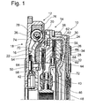
- an inventively constructed multi-plate clutch 10 is shown in conjunction with a constructed in the manner of a dual-mass flywheel torsional vibration damper 12.
- the multi-disc clutch 10, here designed as a double-disc clutch comprises an input region 14 which is fixedly coupled to a secondary side 16 of the torsional vibration damper 12.
- a primary side 18 of the torsional vibration damper 12 is to be connected in a manner known per se to a drive shaft, for example a crankshaft of an internal combustion engine.
- the input portion 14 of the multi-plate clutch 10 comprises an effective as a centrifugal mass abutment plate 20 which is fixedly connected in its radially inner region with a central disk element 22 of the secondary side 16 and is fixedly connected radially outwardly with a housing 24 of the multi-plate clutch 10.
- an intermediate plate 26 is provided, and between the intermediate plate 26 and the housing 24, a pressure plate 28 is provided.
- the pressure plate 28 extends radially outward with support portions 30, the housing 24 and is acted upon there by a trained example as a diaphragm spring force application arrangement 32, the radially further inside over spacer bolts 34 or the like.
- the Kraftbeetzschungsan angel 32 so for example diaphragm spring, generates an engagement force and thus presses the pressure plate 28 in the direction of the intermediate plate 26.
- the intermediate plate 26 is supported relative to the abutment plate 20 via a plurality of circumferentially spaced tangential plate springs 36, the tangential plate springs 36 providing a force urging the intermediate plate 26 away from the abutment plate 20.
- a second group of tangential leaf springs 38 acts between the intermediate plate 26 and the pressure plate 28, is thus fixed to these two plates and generates a force which acts on the intermediate plate 26 and the pressure plate 28 in the direction away from each other.
- the two groups of tangential leaf springs or generally spring elements 36, 38 thus generate a release force for the multi-disc clutch 10, so that the clutch is brought into a disengaged state in the event of a lack or suspension of action by the force application arrangement 32 by the action of the tangential leaf springs 36.
- a generally designated 40 clutch disk assembly comprises in its radially outer region two clutch plates 42, 44. These two clutch plates 42, 44 which are axially displaceable with respect to each other by appropriate design, are radially inwardly coupled via a Torsionsschwingungsdämpferan Aunt 46 to a common hub 48 and Thus, with an output shaft, such as a transmission input shaft, coupled for rotation.
- Each of the clutch plates 42, 44 comprises ring-like or segment-like friction linings 50, 52, via respective pad springs 54, 56 on pad carriers 58, 60 are worn.
- the friction linings 50 and 52 are axially elastically supported on the respective pad carriers 58, 60.
- the abutment plate 20 In association with the first clutch disk 42, the abutment plate 20 has a first friction surface 62, and the intermediate plate 26 has a second friction surface 64. In association with the second clutch disk 44, the intermediate plate 26 has a third friction surface 66 and, in a corresponding manner, the pressure plate 28 has a fourth friction surface 68.
- the first friction surface 62 and the second friction surface 64 in conjunction with the first clutch disk 42 form a first torque transmission region 70 and the third friction surface 66 in conjunction with the fourth friction surface 68 and the second clutch disk 44 a second torque transmission region 72 of the multi-plate clutch 10.
- the primary side 18 thereof comprises two cover disk elements 74, 76 which form a space radially for receiving damping elements 78, for example helical compression springs, and support them in the circumferential direction.
- the central disk element 22 engages in this space radially outward and also forms support areas for the damper elements 78, so that under compression of these damper elements 78, the primary side 18 and the secondary side 16 in the circumferential direction with respect to each other are rotatable.
- the two clutch plates 42, 44 are dimensioned differently.
- the clutch disc 42 has a smaller average friction radius than the clutch disc 44 and is therefore dimensioned so that it ends clearly radially within the damper elements 78.
- the first torque transmitting portion 70 of the multi-plate clutch 10th be designed so that it dips radially into the torsional vibration damper 12 radially within the damper elements 78, so overlaps with this so partially. It is thus initially provided for an axially very compact design.
- the two clutch plates 42, 44 and the friction linings 50, 52 are not only different dimensions, but preferably also constructed of different materials.
- the larger mean friction radius second clutch plate 44 is constructed with organic materials, such as glass or polymer fiber yarns and copper and brass wire embedded in a mixture of resin, rubber, and fillers
- the smaller average friction radius is first Clutch disc 42 constructed with friction linings 50 of inorganic material, such as ceramic, carbon fiber or sintered materials.
- Such inorganic friction lining materials have the advantage that they provide a higher coefficient of friction with lower thermal sensitivity, so that, firstly, the arrangement in a comparatively strongly shielded space can not lead to overheating damage of the friction linings 50, and secondly, the lower average friction radius , which in itself brings a lower transmissible torque, can be compensated by the higher coefficient of friction.
- the built with organic material friction linings 52 of the second clutch plate 44 have the advantage that, although these are thermally sensitive, but also can be better cooled, they provide a significantly higher comfort when engaging, so less prone to plucking or to generate noise ,
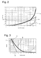
- FIG. 2 It can be seen here applied over the path of the pressure plate 28 via the multi-plate clutch 10 transmitted torque, plotted in Nm.
- a line a drawn in black represents the torque component transmitted when the engagement process is carried out via the second torque transmission region 72, that is, the second clutch disk 44. This increases progressively upon movement of the pressure plate in the direction of engagement, which is primarily due to the vote of the spring force of the tangential leaf springs 38 on the spring force of the pad suspension 56.
- the curve b represents a corresponding torque curve for the first torque transmission region 70. It can be seen that this only when the Anpressplattenweg example, based on a fully engaged positioning "0" falls below the value of 0.4, begins to transmit a torque.
- the increase here may initially be linear, and where there is no further elasticity within the clutch disc 42 itself due to then complete compression of the lining suspension 54 of the clutch disk 42, a kink and subsequently a steeper rise in the torque transferable via this torque transfer area 70 can be seen , Thus, a course marked with the thick line c results for the total torque that can be transmitted via the multi-plate clutch 10. It can be seen that where the first torque transmission region 70 also begins to transmit torque, there is a kink or steeper then, for example, more linear increase in the torque characteristic.
- This kink that is, the additional insertion of the first torque-transmitting region 70, is approximately at a torque value corresponding to a represented by the line d tire slip limit of such a multi-plate clutch 10 equipped vehicle. Up to this tire slip limit, ie the corresponding transmitted via the drive train torque, this can be transmitted to a road without spinning the tires, while with greater torque, the risk of racing through these tires.
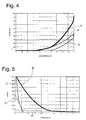
- FIG. 3 shows, in association with FIG. 2, how the forces acting on the intermediate plate 26 change as a function of the relative movement or the relative positioning of the friction surfaces 62, 64 and 66, 68 assigned to a respective torque transmission region 70 or 72 .
- the force of the tangential leaf springs 38 in response to the relative positioning of the two, this associated friction surfaces 66 and 68.
- the force of the tangential leaf springs 36 depending on the relative positioning or the relative movement of the two friction surfaces 62 and 64.
- the drawn with a thicker line curve g indicates the force with which the intermediate plate 26 is loaded, generated by the pad spring 56 of the clutch disc 44 and also on the pressure plate 28 is supported tangential leaf springs 38th
- the curve h represents the force acting on the intermediate plate 26 upon activation of the first torque-transmitting region 70, which is primarily due to the spring force of the tangential leaf springs 36 and the spring force of the lining suspension 54.
- the tangential leaf springs 38 are very soft, so that it is ensured that, coming from a fully disengaged positioning, essentially only the tangential leaf springs 38 are initially compressed and thus only the torque transmission area 72 becomes active ,
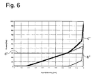
- Figs. 4 and 5 show a different spring design. It can be seen in FIG. 4 that the second torque transmission region 72 represented by the torque curve b 'already begins to transmit a torque considerably earlier, so that a torque is still transmitted significantly before the slip limit is reached via both torque transmission regions 70 and 72. It can also be seen that primarily by the design of the tangential leaf springs 38, the torque characteristic curve b 'starts at a slope of 0 where the second torque transmission region 72 starts to transmit a torque. This means that even in the total torque c 'is not the visible in Fig. 2 kink is present, but a gradual and thus accompanied with greater comfort, progressive torque increase is present. The fact, that even in the curve b 'kinking is clearly visible only later, is due to the vote of the pad suspension 56 on the tangential leaf springs 38.
- FIG. 6 shows a further alternative of the spring adjustment or the tuning of the two torque transmission areas 70, 72 when performing engagement processes or disengaging operations.
- the first torque transmission region 70 here represented by the curve b ", becomes active only when the torque transmitted via the multi-plate clutch 10 is in the region of the tire slip limit d".
- the gradient of the characteristic curve b "at the beginning of the torque transmission via this first torque transmission region 70 can also be almost zero.
- the multi-plate clutch 10 constructed according to the invention can be varied in various aspects.
- the above-described tangential leaf springs 36, 38 can be replaced by other types of springs such as, for example Helical compression springs or the like.
- the multi-disc clutch 10 can be connected to a drive shaft, for example via a starter-generator arrangement, possibly combined with a torsional vibration damper.
- the multi-plate clutch as shown in Fig. 1, can be configured as a dry-running clutch, but of course can also be designed as a wet-running clutch, in which the interaction with each other in frictional interaction surfaces at least partially move in a flowable medium in order to obtain a lubricating or cooling effect.
- Torque transmission behavior in association with the various clutch discs does not necessarily mean that the maximum torque transferable via these two clutch discs, for example, must differ in the fully engaged state.
- the different Drehmomentübertragugns may affect the different time effectiveness in performing engagement events or Auskuppelvor réellen that affect influencing by the selection of frictionally acting materials Kupplungskupfen, may relate to the thermal behavior and may of course also relate to the transmittable torque, in particular by the selection of materials and can be influenced by the selection of the average friction radius or the entire rubbing effect becoming effective surface in association with a respective clutch disc.
- a lower average friction radius for example, obtaining a same maximum transmittable torque, can be compensated by correspondingly larger coefficients of friction of the respective materials to be selected.
Landscapes
- Engineering & Computer Science (AREA)
- General Engineering & Computer Science (AREA)
- Mechanical Engineering (AREA)
- Mechanical Operated Clutches (AREA)
Applications Claiming Priority (2)
| Application Number | Priority Date | Filing Date | Title |
|---|---|---|---|
| DE102006043282 | 2006-09-14 | ||
| DE102007037560A DE102007037560A1 (de) | 2006-09-14 | 2007-08-09 | Mehrscheibenkupplung für den Antriebsstrang eines Fahrzeugs |
Publications (3)
| Publication Number | Publication Date |
|---|---|
| EP1900952A2 true EP1900952A2 (fr) | 2008-03-19 |
| EP1900952A3 EP1900952A3 (fr) | 2009-11-18 |
| EP1900952B1 EP1900952B1 (fr) | 2011-11-09 |
Family
ID=38776123
Family Applications (1)
| Application Number | Title | Priority Date | Filing Date |
|---|---|---|---|
| EP20070017253 Not-in-force EP1900952B1 (fr) | 2006-09-14 | 2007-09-04 | Embrayage à plusieurs disques pour un conducteur de commande d'un véhicule |
Country Status (1)
| Country | Link |
|---|---|
| EP (1) | EP1900952B1 (fr) |
Family Cites Families (4)
| Publication number | Priority date | Publication date | Assignee | Title |
|---|---|---|---|---|
| DE1952620C3 (de) * | 1969-10-18 | 1979-03-29 | Fichtel & Sachs Ag, 8720 Schweinfurt | Dämpfungseinrichtung für eine Mehrscheibenkupplung, insbesondere Zweischeibenkupplung |
| DE10218365A1 (de) * | 2001-03-24 | 2002-10-10 | Zf Sachs Ag | Mehrscheibenkupplung |
| DE102005049669A1 (de) * | 2004-10-26 | 2006-04-27 | Luk Lamellen Und Kupplungsbau Beteiligungs Kg | Kupplungsscheibenanordnung für eine Mehrscheibenkupplung |
| DE102005012820A1 (de) * | 2005-03-17 | 2006-10-05 | Zf Friedrichshafen Ag | Drehmomentübertragungssystem |
-
2007
- 2007-09-04 EP EP20070017253 patent/EP1900952B1/fr not_active Not-in-force
Also Published As
| Publication number | Publication date |
|---|---|
| EP1900952A3 (fr) | 2009-11-18 |
| EP1900952B1 (fr) | 2011-11-09 |
Similar Documents
| Publication | Publication Date | Title |
|---|---|---|
| DE10134118B4 (de) | Doppelkupplung | |
| EP3377783B1 (fr) | Embrayage à friction présentant un axe de rotation | |
| WO2015144162A2 (fr) | Embrayage de construction en tôle muni d'au moins deux disques d'embrayage | |
| EP1134447B1 (fr) | Configuration de double embrayage | |
| DE102018120846A1 (de) | Hybridmodul mit Trennkupplung | |
| WO2020030220A1 (fr) | Module hybride à axe de rotation pour chaîne cinématique d'un véhicule automobile | |
| WO2011116745A1 (fr) | Double embrayage | |
| EP1302687B1 (fr) | Dispositif à embrayages multiples | |
| DE102013215079A1 (de) | Doppelkupplung | |
| EP3123043A2 (fr) | Double embrayage à disques multiples | |
| DE102018103521B4 (de) | Hybridmodul mit einer Rotationsachse | |
| EP1589248A1 (fr) | Procédé pour actionner un système automatisé d'embrayage | |
| EP1900952B1 (fr) | Embrayage à plusieurs disques pour un conducteur de commande d'un véhicule | |
| DE102007037560A1 (de) | Mehrscheibenkupplung für den Antriebsstrang eines Fahrzeugs | |
| DE102018103524A1 (de) | Hybridmodul mit einer Rotationsachse | |
| DE10241027A1 (de) | Mehrfach-Kupplungsanordnung | |
| DE102021108412B3 (de) | Trennkupplung für Hybridmodul, und Hybridmodul | |
| EP4193075B1 (fr) | Embrayage de coupure normalement fermé et actionné par fluide avec un actionneur tournant étant en chevauchement axial avec un amortisseur | |
| DE102019130603B4 (de) | Hybridmodul für einen Antriebsstrang eines Kraftfahrzeugs | |
| DE102018103519A1 (de) | Hybridmodul mit einer Rotationsachse | |
| DE102017103022A1 (de) | Hybrid-Antriebsstrang-Anordnung mit einer Normally-Open-Trennkupplung | |
| EP1876367B1 (fr) | Système d'embrayage multidisques, en particulier pour véhicules utilitaires | |
| DE10329194A1 (de) | Drehmomentübertragungssystem für einen Fahrzeugantriebsstrang | |
| DE10201914B4 (de) | Reibungskupplung | |
| EP2087252A1 (fr) | Embrayage à friction pour la chaîne cinématique d'un véhicule |
Legal Events
| Date | Code | Title | Description |
|---|---|---|---|
| PUAI | Public reference made under article 153(3) epc to a published international application that has entered the european phase |
Free format text: ORIGINAL CODE: 0009012 |
|
| AK | Designated contracting states |
Kind code of ref document: A2 Designated state(s): AT BE BG CH CY CZ DE DK EE ES FI FR GB GR HU IE IS IT LI LT LU LV MC MT NL PL PT RO SE SI SK TR |
|
| AX | Request for extension of the european patent |
Extension state: AL BA HR MK YU |
|
| PUAL | Search report despatched |
Free format text: ORIGINAL CODE: 0009013 |
|
| AK | Designated contracting states |
Kind code of ref document: A3 Designated state(s): AT BE BG CH CY CZ DE DK EE ES FI FR GB GR HU IE IS IT LI LT LU LV MC MT NL PL PT RO SE SI SK TR |
|
| AX | Request for extension of the european patent |
Extension state: AL BA HR MK RS |
|
| 17P | Request for examination filed |
Effective date: 20100421 |
|
| 17Q | First examination report despatched |
Effective date: 20100601 |
|
| AKX | Designation fees paid |
Designated state(s): AT BE BG CH CY CZ DE DK EE ES FI FR GB GR HU IE IS IT LI LT LU LV MC MT NL PL PT RO SE SI SK TR |
|
| GRAP | Despatch of communication of intention to grant a patent |
Free format text: ORIGINAL CODE: EPIDOSNIGR1 |
|
| GRAS | Grant fee paid |
Free format text: ORIGINAL CODE: EPIDOSNIGR3 |
|
| GRAA | (expected) grant |
Free format text: ORIGINAL CODE: 0009210 |
|
| AK | Designated contracting states |
Kind code of ref document: B1 Designated state(s): AT BE BG CH CY CZ DE DK EE ES FI FR GB GR HU IE IS IT LI LT LU LV MC MT NL PL PT RO SE SI SK TR |
|
| REG | Reference to a national code |
Ref country code: GB Ref legal event code: FG4D Free format text: NOT ENGLISH |
|
| REG | Reference to a national code |
Ref country code: CH Ref legal event code: EP |
|
| REG | Reference to a national code |
Ref country code: IE Ref legal event code: FG4D Free format text: LANGUAGE OF EP DOCUMENT: GERMAN |
|
| REG | Reference to a national code |
Ref country code: DE Ref legal event code: R096 Ref document number: 502007008619 Country of ref document: DE Effective date: 20120126 |
|
| REG | Reference to a national code |
Ref country code: NL Ref legal event code: VDEP Effective date: 20111109 |
|
| LTIE | Lt: invalidation of european patent or patent extension |
Effective date: 20111109 |
|
| PG25 | Lapsed in a contracting state [announced via postgrant information from national office to epo] |
Ref country code: LT Free format text: LAPSE BECAUSE OF FAILURE TO SUBMIT A TRANSLATION OF THE DESCRIPTION OR TO PAY THE FEE WITHIN THE PRESCRIBED TIME-LIMIT Effective date: 20111109 Ref country code: IS Free format text: LAPSE BECAUSE OF FAILURE TO SUBMIT A TRANSLATION OF THE DESCRIPTION OR TO PAY THE FEE WITHIN THE PRESCRIBED TIME-LIMIT Effective date: 20120309 |
|
| PG25 | Lapsed in a contracting state [announced via postgrant information from national office to epo] |
Ref country code: NL Free format text: LAPSE BECAUSE OF FAILURE TO SUBMIT A TRANSLATION OF THE DESCRIPTION OR TO PAY THE FEE WITHIN THE PRESCRIBED TIME-LIMIT Effective date: 20111109 Ref country code: PT Free format text: LAPSE BECAUSE OF FAILURE TO SUBMIT A TRANSLATION OF THE DESCRIPTION OR TO PAY THE FEE WITHIN THE PRESCRIBED TIME-LIMIT Effective date: 20120309 Ref country code: SE Free format text: LAPSE BECAUSE OF FAILURE TO SUBMIT A TRANSLATION OF THE DESCRIPTION OR TO PAY THE FEE WITHIN THE PRESCRIBED TIME-LIMIT Effective date: 20111109 Ref country code: GR Free format text: LAPSE BECAUSE OF FAILURE TO SUBMIT A TRANSLATION OF THE DESCRIPTION OR TO PAY THE FEE WITHIN THE PRESCRIBED TIME-LIMIT Effective date: 20120210 Ref country code: PL Free format text: LAPSE BECAUSE OF FAILURE TO SUBMIT A TRANSLATION OF THE DESCRIPTION OR TO PAY THE FEE WITHIN THE PRESCRIBED TIME-LIMIT Effective date: 20111109 Ref country code: LV Free format text: LAPSE BECAUSE OF FAILURE TO SUBMIT A TRANSLATION OF THE DESCRIPTION OR TO PAY THE FEE WITHIN THE PRESCRIBED TIME-LIMIT Effective date: 20111109 Ref country code: SI Free format text: LAPSE BECAUSE OF FAILURE TO SUBMIT A TRANSLATION OF THE DESCRIPTION OR TO PAY THE FEE WITHIN THE PRESCRIBED TIME-LIMIT Effective date: 20111109 |
|
| REG | Reference to a national code |
Ref country code: IE Ref legal event code: FD4D |
|
| PG25 | Lapsed in a contracting state [announced via postgrant information from national office to epo] |
Ref country code: CY Free format text: LAPSE BECAUSE OF FAILURE TO SUBMIT A TRANSLATION OF THE DESCRIPTION OR TO PAY THE FEE WITHIN THE PRESCRIBED TIME-LIMIT Effective date: 20111109 |
|
| PG25 | Lapsed in a contracting state [announced via postgrant information from national office to epo] |
Ref country code: IE Free format text: LAPSE BECAUSE OF FAILURE TO SUBMIT A TRANSLATION OF THE DESCRIPTION OR TO PAY THE FEE WITHIN THE PRESCRIBED TIME-LIMIT Effective date: 20111109 Ref country code: BG Free format text: LAPSE BECAUSE OF FAILURE TO SUBMIT A TRANSLATION OF THE DESCRIPTION OR TO PAY THE FEE WITHIN THE PRESCRIBED TIME-LIMIT Effective date: 20120209 Ref country code: DK Free format text: LAPSE BECAUSE OF FAILURE TO SUBMIT A TRANSLATION OF THE DESCRIPTION OR TO PAY THE FEE WITHIN THE PRESCRIBED TIME-LIMIT Effective date: 20111109 Ref country code: EE Free format text: LAPSE BECAUSE OF FAILURE TO SUBMIT A TRANSLATION OF THE DESCRIPTION OR TO PAY THE FEE WITHIN THE PRESCRIBED TIME-LIMIT Effective date: 20111109 Ref country code: CZ Free format text: LAPSE BECAUSE OF FAILURE TO SUBMIT A TRANSLATION OF THE DESCRIPTION OR TO PAY THE FEE WITHIN THE PRESCRIBED TIME-LIMIT Effective date: 20111109 Ref country code: SK Free format text: LAPSE BECAUSE OF FAILURE TO SUBMIT A TRANSLATION OF THE DESCRIPTION OR TO PAY THE FEE WITHIN THE PRESCRIBED TIME-LIMIT Effective date: 20111109 |
|
| PG25 | Lapsed in a contracting state [announced via postgrant information from national office to epo] |
Ref country code: RO Free format text: LAPSE BECAUSE OF FAILURE TO SUBMIT A TRANSLATION OF THE DESCRIPTION OR TO PAY THE FEE WITHIN THE PRESCRIBED TIME-LIMIT Effective date: 20111109 Ref country code: IT Free format text: LAPSE BECAUSE OF FAILURE TO SUBMIT A TRANSLATION OF THE DESCRIPTION OR TO PAY THE FEE WITHIN THE PRESCRIBED TIME-LIMIT Effective date: 20111109 |
|
| PLBE | No opposition filed within time limit |
Free format text: ORIGINAL CODE: 0009261 |
|
| STAA | Information on the status of an ep patent application or granted ep patent |
Free format text: STATUS: NO OPPOSITION FILED WITHIN TIME LIMIT |
|
| 26N | No opposition filed |
Effective date: 20120810 |
|
| REG | Reference to a national code |
Ref country code: DE Ref legal event code: R097 Ref document number: 502007008619 Country of ref document: DE Effective date: 20120810 |
|
| PGFP | Annual fee paid to national office [announced via postgrant information from national office to epo] |
Ref country code: FR Payment date: 20120926 Year of fee payment: 6 |
|
| BERE | Be: lapsed |
Owner name: ZF FRIEDRICHSHAFEN A.G. Effective date: 20120930 |
|
| PG25 | Lapsed in a contracting state [announced via postgrant information from national office to epo] |
Ref country code: MC Free format text: LAPSE BECAUSE OF NON-PAYMENT OF DUE FEES Effective date: 20120930 Ref country code: ES Free format text: LAPSE BECAUSE OF FAILURE TO SUBMIT A TRANSLATION OF THE DESCRIPTION OR TO PAY THE FEE WITHIN THE PRESCRIBED TIME-LIMIT Effective date: 20120220 |
|
| REG | Reference to a national code |
Ref country code: CH Ref legal event code: PL |
|
| GBPC | Gb: european patent ceased through non-payment of renewal fee |
Effective date: 20120904 |
|
| PG25 | Lapsed in a contracting state [announced via postgrant information from national office to epo] |
Ref country code: FI Free format text: LAPSE BECAUSE OF FAILURE TO SUBMIT A TRANSLATION OF THE DESCRIPTION OR TO PAY THE FEE WITHIN THE PRESCRIBED TIME-LIMIT Effective date: 20111109 |
|
| PG25 | Lapsed in a contracting state [announced via postgrant information from national office to epo] |
Ref country code: GB Free format text: LAPSE BECAUSE OF NON-PAYMENT OF DUE FEES Effective date: 20120904 Ref country code: CH Free format text: LAPSE BECAUSE OF NON-PAYMENT OF DUE FEES Effective date: 20120930 Ref country code: BE Free format text: LAPSE BECAUSE OF NON-PAYMENT OF DUE FEES Effective date: 20120930 Ref country code: LI Free format text: LAPSE BECAUSE OF NON-PAYMENT OF DUE FEES Effective date: 20120930 |
|
| REG | Reference to a national code |
Ref country code: AT Ref legal event code: MM01 Ref document number: 532978 Country of ref document: AT Kind code of ref document: T Effective date: 20120904 |
|
| PG25 | Lapsed in a contracting state [announced via postgrant information from national office to epo] |
Ref country code: MT Free format text: LAPSE BECAUSE OF FAILURE TO SUBMIT A TRANSLATION OF THE DESCRIPTION OR TO PAY THE FEE WITHIN THE PRESCRIBED TIME-LIMIT Effective date: 20111109 |
|
| PG25 | Lapsed in a contracting state [announced via postgrant information from national office to epo] |
Ref country code: AT Free format text: LAPSE BECAUSE OF NON-PAYMENT OF DUE FEES Effective date: 20120904 |
|
| PG25 | Lapsed in a contracting state [announced via postgrant information from national office to epo] |
Ref country code: TR Free format text: LAPSE BECAUSE OF FAILURE TO SUBMIT A TRANSLATION OF THE DESCRIPTION OR TO PAY THE FEE WITHIN THE PRESCRIBED TIME-LIMIT Effective date: 20111109 |
|
| PG25 | Lapsed in a contracting state [announced via postgrant information from national office to epo] |
Ref country code: LU Free format text: LAPSE BECAUSE OF NON-PAYMENT OF DUE FEES Effective date: 20120904 |
|
| REG | Reference to a national code |
Ref country code: FR Ref legal event code: ST Effective date: 20140530 |
|
| PG25 | Lapsed in a contracting state [announced via postgrant information from national office to epo] |
Ref country code: HU Free format text: LAPSE BECAUSE OF FAILURE TO SUBMIT A TRANSLATION OF THE DESCRIPTION OR TO PAY THE FEE WITHIN THE PRESCRIBED TIME-LIMIT Effective date: 20070904 |
|
| PG25 | Lapsed in a contracting state [announced via postgrant information from national office to epo] |
Ref country code: FR Free format text: LAPSE BECAUSE OF NON-PAYMENT OF DUE FEES Effective date: 20130930 |
|
| PGFP | Annual fee paid to national office [announced via postgrant information from national office to epo] |
Ref country code: DE Payment date: 20150902 Year of fee payment: 9 |
|
| REG | Reference to a national code |
Ref country code: DE Ref legal event code: R119 Ref document number: 502007008619 Country of ref document: DE |
|
| PG25 | Lapsed in a contracting state [announced via postgrant information from national office to epo] |
Ref country code: DE Free format text: LAPSE BECAUSE OF NON-PAYMENT OF DUE FEES Effective date: 20170401 |