EP1900600A2 - Central lock device of an adjustable steering column assembly - Google Patents
Central lock device of an adjustable steering column assembly Download PDFInfo
- Publication number
- EP1900600A2 EP1900600A2 EP07075768A EP07075768A EP1900600A2 EP 1900600 A2 EP1900600 A2 EP 1900600A2 EP 07075768 A EP07075768 A EP 07075768A EP 07075768 A EP07075768 A EP 07075768A EP 1900600 A2 EP1900600 A2 EP 1900600A2
- Authority
- EP
- European Patent Office
- Prior art keywords
- centerline
- lever
- lock device
- outward
- carrier
- Prior art date
- Legal status (The legal status is an assumption and is not a legal conclusion. Google has not performed a legal analysis and makes no representation as to the accuracy of the status listed.)
- Granted
Links
- 238000005096 rolling process Methods 0.000 claims description 20
- 230000000712 assembly Effects 0.000 description 3
- 238000000429 assembly Methods 0.000 description 3
- 238000004806 packaging method and process Methods 0.000 description 2
- 231100000136 action limit Toxicity 0.000 description 1
- 230000008878 coupling Effects 0.000 description 1
- 238000010168 coupling process Methods 0.000 description 1
- 238000005859 coupling reaction Methods 0.000 description 1
- 230000000694 effects Effects 0.000 description 1
- 238000004519 manufacturing process Methods 0.000 description 1
Images




Classifications
-
- B—PERFORMING OPERATIONS; TRANSPORTING
- B62—LAND VEHICLES FOR TRAVELLING OTHERWISE THAN ON RAILS
- B62D—MOTOR VEHICLES; TRAILERS
- B62D1/00—Steering controls, i.e. means for initiating a change of direction of the vehicle
- B62D1/02—Steering controls, i.e. means for initiating a change of direction of the vehicle vehicle-mounted
- B62D1/16—Steering columns
- B62D1/18—Steering columns yieldable or adjustable, e.g. tiltable
- B62D1/184—Mechanisms for locking columns at selected positions
Definitions
- the present invention relates to an adjustable steering column assembly for a vehicle, and more particularly to a central lock device of the adjustable steering column assembly having a roller actuator.
- Known adjustable steering column assemblies can be adjusted in a longitudinal or telescoping direction and in a tilt direction.
- the longitudinal direction moves a steering wheel forward and rearward with respect to the vehicle and thus farther or closer to the driver.
- the tilt direction generally moves and tilts the steering in a vertical direction, thus closer or further away from a lap of the driver.
- the driver To adjust the steering column assembly, the driver must first unlock a lock device before the steering column assembly will move.
- the tilt adjustment and the telescoping adjustment features each have there own lock device.
- a single lock device will release the assembly for both adjustments.
- actuating levers of known lock devices are typically orientated on either the left or right hand sides of the steering column and actuated via a pivoting movement. This orientation and the required pivoting action limit packaging ability of the assembly and can restrict comfort and convenience for the driver.
- known levers are typically mounted to a stationary bracket of the assembly thus do not move with respect to the steering wheel. Thus and in reference to the steering wheel, the position of the lever changes and may not be ideally positioned through the adjustment range of the assembly.
- An adjustable steering column assembly of a vehicle has a central lock device for selectably locking an adjustable steering housing and co-extending steering shaft to a stationary bracket or chassis.
- the steering housing and shaft are together adjustable with respect to the bracket.
- the lock device has a roller actuator preferably having inner outer members with a lever supported operably in between by a guide feature for movement along a first centerline substantially parallel to the steering shaft.
- cam couplers are located between the outer member and the lever and the inner member and the lever for converting movement of the lever along the centerline to longitudinal movement of a carrier that traverses the centerline.
- the carrier operates at least one indexing apparatus supported between the carrier and the housing and/or bracket for longitudinal and/or tilt adjustment of the steering column assembly.
- the indexing apparatuses move between locked and unlocked positions upon the longitudinal motion of the carrier as a result of the push/pull action of the lever.
- Each cam coupler may have a rolling pin located in respective resesses of the members for rolling motion against the lever.
- Objects, features and advantages of the present invention include an adjustable steering column assembly having a central lock device that enables a central orientation of a push/pull lever of the device. Moreover, because the lever actuates in a direction substantially parallel to the axis of the steering column and the roller apparatus generally moves with the steering wheel, versatility in the overall packaging of the assembly is improved and operating convenience for the driver is enhanced.
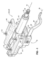
- Figure 1 is a perspective view of an adjustable steering column assembly of the present invention illustrated in a tilt down state and retracted position;
- Figure 2 is a perspective view of the adjustable steering column assembly illustrated in a tilt down state and extended position
- Figure 3 is a perspective view of the adjustable steering column assembly illustrated in a tilt up state and extended position
- Figure 4 is a perspective view of a shuttle portion and a bracket of the assembly with other parts removed to show internal detail;
- Figure 5 is a partial perspective view of the steering column assembly illustrating longitudinal and tilt indexing apparatuses of a central lock device of the assembly;
- Figure 6 is an exploded perspective view of a roller actuator of the central lock device
- Figure 7 is a partial cross section of the central lock device in an unlocked position
- Figure 8 is a partial cross section of the central lock device similar in perspective to Figure 7 except illustrated in a locked position;
- Figure 9 is a plan view of a cam member of the roller actuator
- Figure 10 is a cross section of the cam member taken along line 10-10 of Figure 9;
- Figure 11 is an exploded perspective view of a second embodiment of a roller actuator of a central lock device
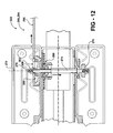
- Figure 12 is a cross section of the central lock device of Figure 11 illustrated in an unlocked position
- Figure 13 is a cross section of the central lock device similar in perspective to Figure 12 except illustrated in a locked position;
- Figure 14 is a partial cross section of a third embodiment of a central lock device.
- an adjustable steering column assembly 20 for a vehicle has a steering shaft 22 that projects rearward with respect to the vehicle and along a rotation axis 24 to a distal end 26 that attaches to a steering wheel (not shown).
- the steering shaft 22 is preferably journaled to and rotates within a tilt housing or steering column 28.
- the housing 28 is support by a bracket 30 of the assembly 20 that engages rigidly to a chassis of the vehicle via a plurality of pins or threaded studs 32 that project preferably upward from the bracket 30 to engage the chassis.
- the pins 32 are may be constructed and arranged to shear or break away from the chassis should the driver forcibly impact the steering wheel during a vehicle collision.
- the housing 28 and co-extending shaft 22 are preferably constructed and arranged to extend and retract longitudinally as a single unit and with respect to the bracket 30 between a retracted position 34 (see Figure 1) and an extended position 36 (see Figure 2).
- a retracted position 34 see Figure 1
- an extended position 36 see Figure 2.
- This forward and rearward movement is not necessarily parallel to rotation axis 24 of steering shaft 22 because the housing 28 and shaft 22 are preferably constructed and arranged to tilt as a single unit between a rake or tilt down state 38 (see Figure 1) and a rake or tilt up state 40 (see Figure 3).
- This tilt adjustment moves the distal end 26 of the steering shaft 22 in an arcuate and substantially vertical direction.
- the housing 28 is generally extended near the extended position 36 and tilt down state 38.
- the housing 28 is generally retracted to near the retracted position 34 and the tilt up state 40.
- the housing 28 has a substantially tubular portion 42 that surrounds and rotatably supports the rotating steering shaft 22, and a support shuttle portion 44 that projects downward from the tubular portion 42.
- the shuttle portion 44 is at least in-part located in the bracket 30 and is supported operably by the bracket.
- the shuttle portion 44 has a cross section that generally forms an upright U-shape having a bottom wall 46 and two opposite side walls 48, 50 that project upward from the bottom wall 46 to rigidly connect to the tubular portion 42.
- the bracket 30 has a bottom panel 52 located immediately beneath the bottom wall 46 of the shuttle portion 44 and two opposite side panels 54, 56 projecting upward from the base panel 52 to preferably engage the vehicle chassis via the pins 32.
- the side panels 54, 56 are located immediately outward from the respective side walls 48, 50 of the shuttle portion 44.
- the side walls 48, 50 and side panels 54, 56 span substantially vertically and are substantially parallel to one another.
- a substantially vertical first slot 58 is located in the first side panel 54 of the bracket 30 and a substantially vertical second slot 60 is located in the second side panel 56 of the bracket 30, both slots 58, 60 enable tilting movement of the housing 28 between the tilt down and tilt up states 38, 40.
- the second slot 60 is defined by opposing longitudinal sides 61, 63 carried by the side panel 56.
- the first side panel 54 that defines the first slot 58 is generally smooth (i.e. is not indexed), and the second side panel 56 is raked or indexed adjacent to the second slot 60 at opposing sides 61, 63 for selection of a tilt position.
- a substantially horizontal third slot 62 is in the first side wall 48 and generally crosses or communicates laterally with the first slot 58
- a substantially horizontal fourth slot 64 is in the second side wall 50 and generally crosses or communicates laterally with the second slot 60.
- the third slot 62 is defined by opposing longitudinal sides 65, 67 carried by the side wall 48.
- the second side wall 50 that defines the fourth slot 64 is generally smooth (i.e is not indexed), and the first side wall 48 is indexed adjacent to the third slot 62 and at sides 65, 67 for selection of a longitudinal or extended/retracted position of the assembly 20.
- the assembly 20 has a central lock device 66 that has a first indexing apparatus 68 for adjusting and locking the longitudinal position of the assembly 20, preferably a second indexing apparatus 70 for adjusting and locking the tilt state of the assembly 20, an roller actuator 72, and a linking carrier or rod 74 that operably links both indexing apparatuses 68, 70 to the common actuator 72.
- the elongated carrier 74 extends through all four slots 58, 62, 64, 60 along a first centerline 76 that is substantially perpendicular to the axis 24 and preferably spaced below the steering shaft 22 and tubular portion 42 of the housing 28.
- the actuator 72 engages a first end 78 of the carrier 74 located outward from the first side panel 54 of the bracket 30.
- the carrier 74 generally carries at least in part the first indexing apparatus 68 at a location between the first and second side walls 48, 50 of the shuttle portion 44, and an opposite second end 80 of the carrier 74 connects and carries at least in part the second indexing apparatus 70 and at a location outward from the second side panel 56 of the bracket 30.
- the indexing apparatuses 68, 70 may be any variety of indexing apparatuses capable of operating with the carrier 74 that moves along the first centerline 76 and in a first direction 77 to place the device 66 in a locked position 82 (see Figure 8) and in an opposite second direction 79 to place the device 66 in an unlocked position 84 (see Figure 7).
- the first end 78 of the carrier 74 is preferably distant from the first side panel 54 of the bracket 30, and when in the unlocked position 84, the first end 78 is closer to or in the proximity of the first side panel 54.
- One such pair of indexing apparatuses 68, 70 is taught in U.S. Patent Application S/N , Attorney Docket No. DP-315044, titled: A Rocker-arm Lock Device of an Adjustable Steering Column Assembly , filed with a common assignee to the present invention and incorporated herein by reference in its entirety.
- the actuator has an elongated lever 86 that may project in a rearward direction 88 with respect to the vehicle and toward the driver, and generally along a centerline 90.
- the lever 86 may be manually actuated in a linear direction along its centerline 90 that generally remains substantially parallel to axis 24 regardless of longitudinal positions 34, 36 and regardless of tilt states 38, 40. Because movement and projection of the lever 86 is substantially parallel to steering axis 24, the lever 86 is generally central to the assembly 20 as oppose to known levers that project radially with respect to a steering shaft and that generally pivot in an imaginary plane that traverses the steering axis.
- Manual movement of the lever 86 from the unlocked position 84 and toward the locked position 82 may act against an axial biasing force generally exerted by springs 91 (see Figure 5) of the indexing apparatuses 68, 70 and with respect to centerline 76 of carrier 74.
- the actuator 72 diverts or converts motion along the centerline 90 of the lever 86 to motion along the intersecting centerline 76 of the carrier 74.
- the actuator 72 has an inner cam member 92 located and preferably supported slidably by the bracket 30, an outer cam member 94 located adjacent to the end 78 of the carrier 74, first and second cam couplers 100, 102 carried between the inner cam member 92 and the end portion 96 of lever 86, and third and fourth cam couplers 104, 106 carried between the outer cam member 94 and the end portion 96.
- the end 78 of the carrier 74 preferably engages threadably a lock nut 108 that prevents disassembly and maintains proper orientation of the actuator 72.
- the carrier 74 projects through a bore 112 (see Figures 9 and 10) in the outer cam member 94 and through a slot 110 in the end portion 96 of the lever 86 that extends longitudinally along the centerline 90, and projects through a bore 112 in the inner member 92 before projecting through the slots 58, 62, 64, 60 in the bracket 30 and housing 28 as previously described.
- the carrier or rod 74 slides axially through the bore 112 in the inner cam member 92 as the carrier 74 moves along centerline 76 between the locked and unlocked positions 82, 84.
- the close relationship between the inner cam member 92 and the sliding carrier or rod 74 acts generally as a bushing to prevent misalignment of the device 66.
- the inner and outer cam members 92, 94 are identical for reducing manufacturing costs and simplifying assembly. Both members 92, 94 have a planar base portion or plate 114 disposed substantially perpendicular to centerline 76.
- the base portion 114 of the inner member 92 generally supports in-part two guide features 116, 118 for multi-directional movement of the actuator 72.
- guide feature or guide track 116 prevents the inner cam member 92 from moving forward or rearward (i.e. horizontally) with respect to the bracket 30 while preferably guiding the actuator 72 vertically during tilt adjustment of the steering column assembly 20.
- the guide track 116 is carried between an inner side of the base portion 114 of the inner member 92 and the bracket 30 at the slot 58.
- the guide track 116 has first and second ribs 120, 122 that project contiguously outward from the inner surface of the base portion 114.
- the first rib 120 projects laterally into the slot 58 in the panel 54 of the bracket 30, and the second rib 122 projects laterally in front of and against a rearward facing edge 124 of the panel 54 for restrained sliding movement.
- the guide track 116 generally prevents or restricts movement of the inner member 92 when the assembly 20 is moving between longitudinal positions 34, 36, and enables guided vertical movement of the roller actuator 72 when the assembly 20 is moving between tilt states 38, 40.
- outer member 94 also has ribs 120, 122. However, ribs 120, 122 of member 94 are not part of feature 116 and thus do not perform a function.
- members 92, 94 may not be identical. If not identical, outer member 94 may be manufactured without ribs 120, 122. Furthermore, the bore 112 of outer member 94 could be threaded for a locking engagement to the threaded end 78 of carrier 74.
- guide feature 118 maintains substantial linear movement of the lever 86 along centerline 90 while permitting slight lateral movement of the lever 86 away from inner member 92 and along centerline 76 when locking the device 66.
- feature 118 has first and second projections 130, 132 projecting outward from the base portion 114 of each member 92, 94.
- the projections 130, 132 are preferably kitty-comer to one another and project axially with respect to centerline 76 and in a direction opposite to the lateral projections of the ribs 120, 122 attached to the respective members 92, 94.
- the feature 118 has respective first and second stanchions 134, 136 projecting radially outward in substantially opposite directions from the base portion 114 of the other member (with respect to centerline 76).
- first and second stanchions 134, 136 projecting radially outward in substantially opposite directions from the base portion 114 of the other member (with respect to centerline 76).
- the projection 130 contiguous to outer member 94 is in sliding contact with stanchion 134 contiguous to inner member 92
- the projection 132 contiguous to outer member 94 is in sliding contact with stanchion 136 contiguous to inner member 92.
- the projections 130, 132 and stanchions 134, 136 of the guide feature 118 enable sliding of the outer member 94 along the centerline 76 and with respect to lever 86, while simultaneously enabling lateral sliding of the lever 86 along the centerline 76 with respect to member 92 and as the device 66 moves between the locked and unlocked positions 82, 84.
- the inward cam couplers 100, 102 are generally positioned diametrically opposite with respect to one another (i.e. positioned one-hundred and eighty degrees apart from one-another) and with respect to the carrier centerline 76.
- coupler 100 is generally located radially outward from the carrier 74 and radially inward from feature 118.
- coupler 102 is generally located radially outward from the carrier 74 and radially inward from feature 118.
- Couplers 104, 106 are diametrically positioned with respect to one another (i.e.
- coupler 104 is generally located radially outward from the carrier 74 and radially inward from feature 118.
- coupler 106 is generally located radially outward from the carrier 74 and radially inward from feature 118.
- the end portion 96 of lever 86 is preferably a flat bar and carries an inward side 146 being of both couplers 100, 102, and an outward side 148 being of both couplers 104, 106.
- the opposite sides 146, 148 flank the edges 126, 128 of the end portion 96, and the slot 110 communicates through both sides 146, 148.
- the inward side 146 faces the inward member 92 and the outward side 148 faces the outward member 94.
- the edges 126, 128 and the sides 146, 148 are substantially parallel to one-another and to the centerline 90.
- Each coupler 100, 102, 104, 106 has a roller or preferably a rolling pin 150 disposed substantially in respective tapered recesses 152, 154 of both members 92, 94.
- Each recess 152, 154 is defined in-part by a bottom surface 156 carried by the base portion 114 and each lying in respective imaginary planes that intersect both centerline 76 and centerline 90.
- Each bottom surface 156 spans between substantially vertical and opposing faces 158, 160 that define in-part each recess 152, 154.
- face 158 faces forward and defines a rearward end of the recess
- face 160 faces rearward and defines a forward end of the recess.
- the forward face 158 is preferably wider than the rearward face 160 due to the tapering effect of the bottom surface 156 and by an amount generally equal to half the throw of the carrier 74 as it moves between locked and unlocked positions 82, 84.
- the width of forward face 158 is substantially equal to the diameter of the rolling pin 150.
- each recess 152, 154 gets deeper in the forward direction with respect to the vehicle.
- the bottom surface 156 of the first coupler 100 is parallel to the bottom surface 156 of the second coupler 102.
- the bottom surface 156 of the third coupler 104 is parallel to the bottom surface 156 of the fourth coupler 106.
- the imaginary planes of the bottom surfaces 156 of the first and second couplers 100, 102 intersect the imaginary planes of the bottom surfaces 156 of the third and fourth couplers 104, 106 along intersecting lines (not shown) that are generally parallel to rolling axes 163 of each rolling pin 150.
- the rolling axes 163 are substantially perpendicular to centerlines 76, 90 and parallel to respective surfaces 156.
- the springs 91 of the indexing apparatuses 68, 70 are orientated to bias the locking device 66 toward the unlocked position 84.
- the end portion 96 of the lever 86 preferably carries a detent or cantilevered tab 164 that resiliently projects flexibly into the slot 110 near a forward facing stop face 166 that generally defines a rearward end of the slot 110 with respect to the vehicle.
- the end portion 96 may also have a second detent or cantilevered tab 168 located near a rearward facing stop face 170 that generally defines a forward end of the slot 110.
- one rolling pin 150 is located in each recess 152, 154 in each member 92, 94 for reducing friction between the lever sides 146, 148 and the bottom surfaces 156 of the respective members 92, 94, and for generally restricting and diverting motion along the centerline 90 to motion along the centerline 76.
- the rolling pins 150 are at the forward end of each respective recess 152, 154 and near or against the rearward face 160, and the carrier 74 is snap fitted directly between the flexible lock tab 164 and stop face 166 of the lever 86.
- the rolling pins 150 are at the rearward end of each respective recess 152, 154 of each member 92, 94 and near or against the forward face 158, and the carrier 74 (in addition to the biasing spring force) may be snap fitted directly between the flexible tab 162 and near or against the stop face 170 of the lever 86.
- the indexing apparatuses 68, 70 are simultaneously placed in the unlocked position 84 (as best shown in Figure 7) when the driver desires to longitudinally and/or tiltably adjust the steering housing 28.
- the lock device 66 is placed in the locked position 82 (as best shown in Figure 8) after the driver has selected a desirable longitudinal position and tilt state for the steering wheel.
- the driver In order to move the device 66 between the unlocked and locked positions 84, 82, the driver respectively pulls and preferably pushes upon the lever 86 of the actuator 72 in a linear direction or along centerline 90.
- the outward cam member 94 moves along centerline 76 and toward the side 148 of the lever 86.
- the device 66 is preferably placed in the unlocked position 84 generally designated when the carrier 74 snap fits past the flexible tab 162 and abouts stop face of the lever 86.
- the rolling pins 150 generally roll about respective axes 163 and from the rearward face 160 and toward the wider forward face 158 defining each recess 152, 154 of each member 92, 94.
- the throw of the lever 86 along centerline 90 and the shifting of the rolling pins 150 in the recesses 152, 154 cause the outer member 94 with the carrier 74 to move along the centerline 76 by a throw, which is great enough to release the indexing apparatuses 68, 70.
- This throw is substantially equal to the difference of the widths between the forward and rearward faces 158, 160.
- the lever 86 of the actuator 72 is pushed by the driver to lock (i.e. forward and away from the driver) and against the biasing force of the springs 91 and resistance of the tab162.
- This action moves the members 92, 94 away from one another and away from respective inner and outer sides 146, 148 of the lever 86 and until the carrier 74 snap locks past the resilient tab 164 and abuts the stop face 166.
- the tab 164 resists the biasing force of the springs 91, thus maintaining the device 66 in the locked state.
- a second embodiment of a central lock device 266 is illustrated wherein like elements to the first embodiment have the same identifying numerals except with the summed addition of two hundred. Unlike device 66, device 266 does not have an outer member, and thus has only two couplings 300, 302 and not four.
- a threaded nut or enlarged head 308 engages a threaded end 278 of a carrier 274. The nut 308 slides directly against an outer surface 348 of a lever 286 as the device moves between unlocked and locked positions 284, 282.
- a third embodiment of a central lock device 366 is illustrated wherein like elements to the first embodiment have the same identifying numerals except with the summed addition of three hundred.
- device 366 has a reversable electric motor 180 with a motor housing engaged rigidly to a steering column housing (not shown) of the vehicle.
- the motor 180 has a rotating shaft or turn buckle 182 that extends substantially parallel to a steering column or a rotation axis of a steering shaft (not shown).
- a lever 386 of the device 366 is threaded to the shaft 182 forming a screw drive arrangement for movement of the lever 286 between locked and unlocked positions along a centerline or direction 390 causing an actuator 372 to move a carrier 374 along a centerline 376 that is substantially perpendicular to centerline 390.
Landscapes
- Engineering & Computer Science (AREA)
- Chemical & Material Sciences (AREA)
- Combustion & Propulsion (AREA)
- Transportation (AREA)
- Mechanical Engineering (AREA)
- Steering Controls (AREA)
Abstract
Description
- The present invention relates to an adjustable steering column assembly for a vehicle, and more particularly to a central lock device of the adjustable steering column assembly having a roller actuator.
- Known adjustable steering column assemblies can be adjusted in a longitudinal or telescoping direction and in a tilt direction. Generally the longitudinal direction moves a steering wheel forward and rearward with respect to the vehicle and thus farther or closer to the driver. The tilt direction generally moves and tilts the steering in a vertical direction, thus closer or further away from a lap of the driver. To adjust the steering column assembly, the driver must first unlock a lock device before the steering column assembly will move. In some known assemblies, the tilt adjustment and the telescoping adjustment features each have there own lock device. In other known assemblies, a single lock device will release the assembly for both adjustments.
- Unfortunately, the actuating levers of known lock devices are typically orientated on either the left or right hand sides of the steering column and actuated via a pivoting movement. This orientation and the required pivoting action limit packaging ability of the assembly and can restrict comfort and convenience for the driver. Moreover, known levers are typically mounted to a stationary bracket of the assembly thus do not move with respect to the steering wheel. Thus and in reference to the steering wheel, the position of the lever changes and may not be ideally positioned through the adjustment range of the assembly.
- An adjustable steering column assembly of a vehicle has a central lock device for selectably locking an adjustable steering housing and co-extending steering shaft to a stationary bracket or chassis. For driver convenience and comfort, the steering housing and shaft are together adjustable with respect to the bracket. The lock device has a roller actuator preferably having inner outer members with a lever supported operably in between by a guide feature for movement along a first centerline substantially parallel to the steering shaft. Preferably, cam couplers are located between the outer member and the lever and the inner member and the lever for converting movement of the lever along the centerline to longitudinal movement of a carrier that traverses the centerline.
- Preferably, the carrier operates at least one indexing apparatus supported between the carrier and the housing and/or bracket for longitudinal and/or tilt adjustment of the steering column assembly. The indexing apparatuses move between locked and unlocked positions upon the longitudinal motion of the carrier as a result of the push/pull action of the lever. Each cam coupler may have a rolling pin located in respective resesses of the members for rolling motion against the lever.
- Objects, features and advantages of the present invention include an adjustable steering column assembly having a central lock device that enables a central orientation of a push/pull lever of the device. Moreover, because the lever actuates in a direction substantially parallel to the axis of the steering column and the roller apparatus generally moves with the steering wheel, versatility in the overall packaging of the assembly is improved and operating convenience for the driver is enhanced.
- These and other objects, features and advantages of this invention will be apparent from the following detailed description, appended claims, and accompanying drawings in which:
- Figure 1 is a perspective view of an adjustable steering column assembly of the present invention illustrated in a tilt down state and retracted position;
- Figure 2 is a perspective view of the adjustable steering column assembly illustrated in a tilt down state and extended position;
- Figure 3 is a perspective view of the adjustable steering column assembly illustrated in a tilt up state and extended position;
- Figure 4 is a perspective view of a shuttle portion and a bracket of the assembly with other parts removed to show internal detail;
- Figure 5 is a partial perspective view of the steering column assembly illustrating longitudinal and tilt indexing apparatuses of a central lock device of the assembly;
- Figure 6 is an exploded perspective view of a roller actuator of the central lock device;
- Figure 7 is a partial cross section of the central lock device in an unlocked position;
- Figure 8 is a partial cross section of the central lock device similar in perspective to Figure 7 except illustrated in a locked position;
- Figure 9 is a plan view of a cam member of the roller actuator;
- Figure 10 is a cross section of the cam member taken along line 10-10 of Figure 9;
- Figure 11 is an exploded perspective view of a second embodiment of a roller actuator of a central lock device;
- Figure 12 is a cross section of the central lock device of Figure 11 illustrated in an unlocked position;
- Figure 13 is a cross section of the central lock device similar in perspective to Figure 12 except illustrated in a locked position; and
- Figure 14 is a partial cross section of a third embodiment of a central lock device.
- Referring now to Figure 1 of the drawings, an adjustable
steering column assembly 20 for a vehicle has asteering shaft 22 that projects rearward with respect to the vehicle and along arotation axis 24 to adistal end 26 that attaches to a steering wheel (not shown). Thesteering shaft 22 is preferably journaled to and rotates within a tilt housing orsteering column 28. Thehousing 28 is support by abracket 30 of theassembly 20 that engages rigidly to a chassis of the vehicle via a plurality of pins or threadedstuds 32 that project preferably upward from thebracket 30 to engage the chassis. Thepins 32 are may be constructed and arranged to shear or break away from the chassis should the driver forcibly impact the steering wheel during a vehicle collision. - The
housing 28 andco-extending shaft 22 are preferably constructed and arranged to extend and retract longitudinally as a single unit and with respect to thebracket 30 between a retracted position 34 (see Figure 1) and an extended position 36 (see Figure 2). When extending, thehousing 28 andshaft 22 move in a linear rearward direction with respect to the vehicle, and when retracting, thehousing 28 andshaft 22 move in a forward direction and generally into thebracket 30. - This forward and rearward movement, however, is not necessarily parallel to
rotation axis 24 ofsteering shaft 22 because thehousing 28 andshaft 22 are preferably constructed and arranged to tilt as a single unit between a rake or tilt down state 38 (see Figure 1) and a rake or tilt up state 40 (see Figure 3). This tilt adjustment moves thedistal end 26 of thesteering shaft 22 in an arcuate and substantially vertical direction. To accommodate drivers of small stature, thehousing 28 is generally extended near the extendedposition 36 and tilt down state 38. To comfortably accommodate drivers of larger stature, thehousing 28 is generally retracted to near the retractedposition 34 and the tilt up state 40. - As best illustrated in Figures 1 and 4, the
housing 28 has a substantiallytubular portion 42 that surrounds and rotatably supports the rotatingsteering shaft 22, and asupport shuttle portion 44 that projects downward from thetubular portion 42. Theshuttle portion 44 is at least in-part located in thebracket 30 and is supported operably by the bracket. Theshuttle portion 44 has a cross section that generally forms an upright U-shape having abottom wall 46 and twoopposite side walls bottom wall 46 to rigidly connect to thetubular portion 42. Correspondingly and as best shown in Figure 5, thebracket 30 has abottom panel 52 located immediately beneath thebottom wall 46 of theshuttle portion 44 and twoopposite side panels base panel 52 to preferably engage the vehicle chassis via thepins 32. With respect toaxis 24, theside panels respective side walls shuttle portion 44. Preferably, theside walls side panels - A substantially vertical
first slot 58 is located in thefirst side panel 54 of thebracket 30 and a substantially verticalsecond slot 60 is located in thesecond side panel 56 of thebracket 30, bothslots housing 28 between the tilt down and tilt up states 38, 40. Thesecond slot 60 is defined by opposinglongitudinal sides side panel 56. Preferably, thefirst side panel 54 that defines thefirst slot 58 is generally smooth (i.e. is not indexed), and thesecond side panel 56 is raked or indexed adjacent to thesecond slot 60 atopposing sides assembly 20 between the retracted andextended positions third slot 62 is in thefirst side wall 48 and generally crosses or communicates laterally with thefirst slot 58, and a substantially horizontalfourth slot 64 is in thesecond side wall 50 and generally crosses or communicates laterally with thesecond slot 60. Thethird slot 62 is defined by opposinglongitudinal sides side wall 48. Preferably, thesecond side wall 50 that defines thefourth slot 64 is generally smooth (i.e is not indexed), and thefirst side wall 48 is indexed adjacent to thethird slot 62 and atsides assembly 20. - Referring to Figures 1, 4 and 5, the
assembly 20 has acentral lock device 66 that has afirst indexing apparatus 68 for adjusting and locking the longitudinal position of theassembly 20, preferably asecond indexing apparatus 70 for adjusting and locking the tilt state of theassembly 20, anroller actuator 72, and a linking carrier orrod 74 that operably links both indexingapparatuses common actuator 72. Theelongated carrier 74 extends through all fourslots first centerline 76 that is substantially perpendicular to theaxis 24 and preferably spaced below thesteering shaft 22 andtubular portion 42 of thehousing 28. Theactuator 72 engages afirst end 78 of thecarrier 74 located outward from thefirst side panel 54 of thebracket 30. Thecarrier 74 generally carries at least in part thefirst indexing apparatus 68 at a location between the first andsecond side walls shuttle portion 44, and an oppositesecond end 80 of thecarrier 74 connects and carries at least in part thesecond indexing apparatus 70 and at a location outward from thesecond side panel 56 of thebracket 30. - The indexing apparatuses 68, 70 may be any variety of indexing apparatuses capable of operating with the
carrier 74 that moves along thefirst centerline 76 and in afirst direction 77 to place thedevice 66 in a locked position 82 (see Figure 8) and in an oppositesecond direction 79 to place thedevice 66 in an unlocked position 84 (see Figure 7). When in the locked position 82, thefirst end 78 of thecarrier 74 is preferably distant from thefirst side panel 54 of thebracket 30, and when in the unlocked position 84, thefirst end 78 is closer to or in the proximity of thefirst side panel 54. One such pair ofindexing apparatuses - Referring to Figures 1 and 6-8 and more specific to the present invention, in the preferred embodiment of the
actuator 72 of thelock device 66, the actuator has an elongatedlever 86 that may project in arearward direction 88 with respect to the vehicle and toward the driver, and generally along acenterline 90. Thelever 86 may be manually actuated in a linear direction along itscenterline 90 that generally remains substantially parallel toaxis 24 regardless oflongitudinal positions lever 86 is substantially parallel to steeringaxis 24, thelever 86 is generally central to theassembly 20 as oppose to known levers that project radially with respect to a steering shaft and that generally pivot in an imaginary plane that traverses the steering axis. Manual movement of thelever 86 from the unlocked position 84 and toward the locked position 82 may act against an axial biasing force generally exerted by springs 91 (see Figure 5) of theindexing apparatuses centerline 76 ofcarrier 74. - Referring to Figures 6-8, the
actuator 72 diverts or converts motion along thecenterline 90 of thelever 86 to motion along the intersectingcenterline 76 of thecarrier 74. To accomplish this, theactuator 72 has aninner cam member 92 located and preferably supported slidably by thebracket 30, anouter cam member 94 located adjacent to theend 78 of thecarrier 74, first andsecond cam couplers inner cam member 92 and theend portion 96 oflever 86, and third andfourth cam couplers outer cam member 94 and theend portion 96. Theend 78 of thecarrier 74 preferably engages threadably alock nut 108 that prevents disassembly and maintains proper orientation of theactuator 72. From the enlarged head ornut 108, thecarrier 74 projects through a bore 112 (see Figures 9 and 10) in theouter cam member 94 and through aslot 110 in theend portion 96 of thelever 86 that extends longitudinally along thecenterline 90, and projects through abore 112 in theinner member 92 before projecting through theslots bracket 30 andhousing 28 as previously described. The carrier orrod 74 slides axially through thebore 112 in theinner cam member 92 as thecarrier 74 moves alongcenterline 76 between the locked and unlocked positions 82, 84. The close relationship between theinner cam member 92 and the sliding carrier orrod 74 acts generally as a bushing to prevent misalignment of thedevice 66. - Preferably, the inner and
outer cam members members plate 114 disposed substantially perpendicular tocenterline 76. Thebase portion 114 of theinner member 92 generally supports in-part two guide features 116, 118 for multi-directional movement of theactuator 72. As best shown in Figures 6-8, guide feature or guidetrack 116 prevents theinner cam member 92 from moving forward or rearward (i.e. horizontally) with respect to thebracket 30 while preferably guiding theactuator 72 vertically during tilt adjustment of thesteering column assembly 20. Theguide track 116 is carried between an inner side of thebase portion 114 of theinner member 92 and thebracket 30 at theslot 58. Preferably, theguide track 116 has first andsecond ribs base portion 114. Thefirst rib 120 projects laterally into theslot 58 in thepanel 54 of thebracket 30, and thesecond rib 122 projects laterally in front of and against a rearward facingedge 124 of thepanel 54 for restrained sliding movement. Theguide track 116 generally prevents or restricts movement of theinner member 92 when theassembly 20 is moving betweenlongitudinal positions roller actuator 72 when theassembly 20 is moving between tilt states 38, 40. - As best shown in Figure 6 and because
members outer member 94 also hasribs ribs member 94 are not part offeature 116 and thus do not perform a function. One skilled in the art would now realize thatmembers outer member 94 may be manufactured withoutribs bore 112 ofouter member 94 could be threaded for a locking engagement to the threadedend 78 ofcarrier 74. - As best shown in Figures 6-8,
guide feature 118 maintains substantial linear movement of thelever 86 alongcenterline 90 while permitting slight lateral movement of thelever 86 away frominner member 92 and alongcenterline 76 when locking thedevice 66. For sliding contact with oppositelongitudinal edges end portion 96 oflever 86, feature 118 has first andsecond projections base portion 114 of eachmember base portion 114 theprojections centerline 76 and in a direction opposite to the lateral projections of theribs respective members - For structural support and respective sliding contact with the
axial projections feature 118 has respective first andsecond stanchions base portion 114 of the other member (with respect to centerline 76). When assembled, theprojection 130 contiguous toinner member 92 is in sliding contact withstanchion 134 contiguous toouter member 94, and theprojection 132 contiguous toinner member 92 is in sliding contact withstanchion 136 contiguous toouter member 94. Similarly, theprojection 130 contiguous toouter member 94 is in sliding contact withstanchion 134 contiguous toinner member 92, and theprojection 132 contiguous toouter member 94 is in sliding contact withstanchion 136 contiguous toinner member 92. Theprojections stanchions guide feature 118 enable sliding of theouter member 94 along thecenterline 76 and with respect to lever 86, while simultaneously enabling lateral sliding of thelever 86 along thecenterline 76 with respect tomember 92 and as thedevice 66 moves between the locked and unlocked positions 82, 84. - For an even or symmetric distribution of camming forces during actuation of
device 66, theinward cam couplers carrier centerline 76. Preferably,coupler 100 is generally located radially outward from thecarrier 74 and radially inward fromfeature 118. Likewise,coupler 102 is generally located radially outward from thecarrier 74 and radially inward fromfeature 118.Couplers carrier centerline 76. Preferably,coupler 104 is generally located radially outward from thecarrier 74 and radially inward fromfeature 118. Likewise,coupler 106 is generally located radially outward from thecarrier 74 and radially inward fromfeature 118. - The
end portion 96 oflever 86 is preferably a flat bar and carries aninward side 146 being of bothcouplers outward side 148 being of bothcouplers opposite sides edges end portion 96, and theslot 110 communicates through bothsides inward side 146 faces theinward member 92 and theoutward side 148 faces theoutward member 94. Theedges sides centerline 90. Eachcoupler rolling pin 150 disposed substantially in respective taperedrecesses members recess bottom surface 156 carried by thebase portion 114 and each lying in respective imaginary planes that intersect bothcenterline 76 andcenterline 90. - Each
bottom surface 156 spans between substantially vertical and opposingfaces recess forward face 158 is preferably wider than therearward face 160 due to the tapering effect of thebottom surface 156 and by an amount generally equal to half the throw of thecarrier 74 as it moves between locked and unlocked positions 82, 84. Preferably, the width offorward face 158 is substantially equal to the diameter of therolling pin 150. Generally, eachrecess bottom surface 156 of thefirst coupler 100 is parallel to thebottom surface 156 of thesecond coupler 102. Similarly, thebottom surface 156 of thethird coupler 104 is parallel to thebottom surface 156 of thefourth coupler 106. The imaginary planes of the bottom surfaces 156 of the first andsecond couplers fourth couplers axes 163 of eachrolling pin 150. The rolling axes 163 are substantially perpendicular tocenterlines respective surfaces 156. - As previously described and in reference to Figures 5 and 6, the
springs 91 of theindexing apparatuses locking device 66 toward the unlocked position 84. To resist this biasing force when thedevice 66 is in the locked position 82, theend portion 96 of thelever 86 preferably carries a detent or cantileveredtab 164 that resiliently projects flexibly into theslot 110 near a forward facingstop face 166 that generally defines a rearward end of theslot 110 with respect to the vehicle. Similarly, theend portion 96 may also have a second detent or cantilevered tab 168 located near a rearward facingstop face 170 that generally defines a forward end of theslot 110. - As previously described in-part and best shown in Figures 7 and 8, one
rolling pin 150 is located in eachrecess member respective members centerline 90 to motion along thecenterline 76. When theactuator 72 is in the locked position 82 (see Figure 8), the rollingpins 150 are at the forward end of eachrespective recess rearward face 160, and thecarrier 74 is snap fitted directly between theflexible lock tab 164 and stopface 166 of thelever 86. When theactuator 72 is in the unlocked position 84 (see Figure 7), the rollingpins 150 are at the rearward end of eachrespective recess member forward face 158, and the carrier 74 (in addition to the biasing spring force) may be snap fitted directly between the flexible tab 162 and near or against thestop face 170 of thelever 86. - During operation of the
lock device 66, theindexing apparatuses housing 28. Thelock device 66 is placed in the locked position 82 (as best shown in Figure 8) after the driver has selected a desirable longitudinal position and tilt state for the steering wheel. In order to move thedevice 66 between the unlocked and locked positions 84, 82, the driver respectively pulls and preferably pushes upon thelever 86 of theactuator 72 in a linear direction or alongcenterline 90. - When the
lever 86 of theroller pin actuator 72 of thelock device 66 is pulled by the driver to unlock (i.e. rearward toward the driver), theoutward cam member 94 moves alongcenterline 76 and toward theside 148 of thelever 86. With continued pulling of thelever 86 and with the biasing assistance of thesprings 91 of therespective indexing apparatuses device 66 is preferably placed in the unlocked position 84 generally designated when thecarrier 74 snap fits past the flexible tab 162 and abouts stop face of thelever 86. - During this pulling action, the rolling
pins 150 generally roll aboutrespective axes 163 and from therearward face 160 and toward the widerforward face 158 defining eachrecess member lever 86 alongcenterline 90 and the shifting of the rollingpins 150 in therecesses outer member 94 with thecarrier 74 to move along thecenterline 76 by a throw, which is great enough to release theindexing apparatuses - When the desired longitudinal position and tilt state of the
assembly 20 is selected, thelever 86 of theactuator 72 is pushed by the driver to lock (i.e. forward and away from the driver) and against the biasing force of thesprings 91 and resistance of the tab162. Continued pushing in the forward direction with respect to the vehicle causes an opposite motion of the rollers as previously explained when unlocking. This action moves themembers outer sides lever 86 and until thecarrier 74 snap locks past theresilient tab 164 and abuts thestop face 166. Once in the locked position 82, thetab 164 resists the biasing force of thesprings 91, thus maintaining thedevice 66 in the locked state. - Referring to Figures 11-13, a second embodiment of a central lock device 266 is illustrated wherein like elements to the first embodiment have the same identifying numerals except with the summed addition of two hundred. Unlike
device 66, device 266 does not have an outer member, and thus has only twocouplings enlarged head 308 engages a threadedend 278 of acarrier 274. Thenut 308 slides directly against anouter surface 348 of alever 286 as the device moves between unlocked and locked positions 284, 282. - Referring to Figure 14, a third embodiment of a
central lock device 366 is illustrated wherein like elements to the first embodiment have the same identifying numerals except with the summed addition of three hundred. Unlikedevices 66, 266 that are generally manual,device 366 has a reversableelectric motor 180 with a motor housing engaged rigidly to a steering column housing (not shown) of the vehicle. Themotor 180 has a rotating shaft or turnbuckle 182 that extends substantially parallel to a steering column or a rotation axis of a steering shaft (not shown). Alever 386 of thedevice 366 is threaded to theshaft 182 forming a screw drive arrangement for movement of thelever 286 between locked and unlocked positions along a centerline ordirection 390 causing anactuator 372 to move acarrier 374 along acenterline 376 that is substantially perpendicular tocenterline 390. - While the forms of the invention herein disclosed constitute presently preferred embodiments, many others are possible. It is not intended herein to mention all the possible equivalent forms or ramifications of the invention. It is understood that terms used herein are merely descriptive, rather than limiting, and that various changes may be made without departing from the spirit or scope of the invention.
Claims (20)
- An adjustable steering column assembly (20) for a vehicle comprising:a bracket (30);a housing (28) supported adjustably by and movable with respect to said bracket;a steering shaft (22) journaled to said housing for rotation about a steering axis (24);a member (92 or 94) supported at least in-part by said bracket;a lever (86) cammed to said member and constructed and arranged to move substantially along a first centerline (90);a carrier (74) engaged slidably to said lever for movement along a second centerline (76) that traverses said first centerline;a first indexing apparatus (68) carried between said carrier and said housing for longitudinal adjustment of the steering column assembly; andwherein movement of said lever along said first centerline causes said carrier to move along said second centerline and between locked and unlocked positions (82, 84).
- The adjustable steering column assembly set forth in claim 1 further comprising:a cam coupler (100, 102, 104 or 106) having a planar surface (156) carried by said member (92 or 94) and a planar side (146 or 148) carried by said lever and opposing said planar surface; andwherein at least one of said planar side and said planar surface lie in an imaginary plane that traverses both said first and second centerlines.
- The adjustable steering column assembly set forth in claim 2 further comprising a rolling pin (150) of said cam coupler being in rolling contact between said inward side and said outward surface and having a rolling axis (163) orientated perpendicular to the first and second centerlines.
- The adjustable steering column assembly set forth in claim 3 further comprising a spring (91) supported compressible between said housing and said first indexing apparatus for biasing said carrier toward said unlocked position.
- The adjustable steering column assembly set forth in claim 4 further comprising a second indexing apparatus (70) carried between said bracket and said carrier for tilt adjustment of the adjustable steering column assembly.
- The adjustable steering column assembly set forth in claim 5 wherein the member is supported slidably by the bracket for movement in a substantially vertical direction during tilt adjustment.
- The adjustable steering column assembly set forth in claim 6 further comprising:said member being an inward member (92);said cam coupler being an inward cam coupler (100 or 102);an outward member (94) fixed to said carrier; andan outward cam coupler (104 or 106) carried between said outward member and said lever.
- A central lock device (66) for an adjustable steering column assembly (20) of a vehicle having a steering shaft (22) rotatable about an axis (24) and a co-extending housing (28) journaled to the shaft and engaged operably to a bracket (30), the central lock device comprising:a member (92 or 94);a carrier (74) constructed and arranged for biased movement with respect to said member and along a first centerline (76) traverse to the axis (24) and between a locked position (82) and an unlocked position (84);a lever (86) connected slidably to the carrier and constructed and arranged for movement substantially along a second centerline (90) that traverses said first centerline for moving said carrier between said locked and unlocked positions; anda cam coupler (100, 102, 104 or 106) having a bottom surface (156) carried by said member, an opposing side (146 or 148) carried by said lever, and a roller (150) located rotatably between said bottom surface and said side for converting movement of said lever along said second centerline to movement of said carrier along said first centerline.
- The central lock device set forth in claim 8 wherein said roller is a rolling pin having an axis (163) disposed perpendicular to said first and second centerlines.
- The central lock device set forth in claim 8 wherein said side is parallel to said second centerline.
- The central lock device set forth in claim 10 wherein said bottom surface is planar and lies in an imaginary plane that traverses said first and second centerlines.
- The central lock device set forth in claim 8 wherein said bottom surface defines in-part a recess (152 or 154) in said member.
- The central lock device set forth in claim 8 wherein said first centerline intersects said second centerline.
- The central lock device set forth in claim 8 further comprising:said member being an inward member (92);said cam coupler being an inward cam coupler (100 or 102);said roller being a first roller associated with said inward cam coupler;an outward member (94) constructed and arranged to move with said carrier;wherein said lever is located between said inward and outward members;
an outward cam coupler (104 or 106) having an inward surface (156) carried by the outward member and an opposing outward side (148) carried by said lever; and
a second roller (150) located rotatably between said inward surface and outward side of said outward cam coupler for converting movement of said lever along said second centerline to movement of said carrier along said first centerline. - The central lock device set forth in claim 8 further comprising:said cam coupler being a first cam coupler (100 or 104);a second cam coupler (102 or 106) carried between said member and said lever;said roller being a first rolling pin (150) having an axis (163) disposed perpendicular to said first and second centerlines; anda second rolling pin (150) associated with said second cam coupler.
- The central lock device set forth in claim 15 wherein said axis of said first rolling pin is parallel to an axis (163) of said second rolling pin.
- The central lock device set forth in claim 15 wherein said second cam coupler has a bottom surface (156) carried by said member and disposed parallel to said bottom surface (156) of said first cam coupler.
- The central lock device set forth in claim 17 wherein said second cam coupler has a side (146 or 148) carried by said lever and opposing said bottom surface of said second cam coupler and being co-planar to said side of said first cam coupler.
- The central lock device set forth in claim 8 further comprising:said member being an inward member (92);said cam coupler being a first inward cam coupler (100);said roller being a first roller (150) of said first inward cam coupler;a second inward cam coupler (102) located diametrically opposite to said first inward cam coupler with respect to said first centerline;a second roller (150) of said second inward cam coupler;an outward member (94) fixed to said carrier;wherein said lever is located between said inward and outward members;
first and second outward cam couplers (104, 106) carried between said outward member and said lever;
third and fourth rollers (150, 150) of said respective first and second outward cam couplers; and
wherein said first outward cam coupler is located diametrically opposite to said second outward cam coupler with respect to said first centerline. - The central lock device set forth in claim 8 further comprising an indexing apparatus (68 or 70) carried in-part by said carrier and having a spring (91 or 91) for biasing said lock device toward said unlocked position.
Applications Claiming Priority (2)
| Application Number | Priority Date | Filing Date | Title |
|---|---|---|---|
| US84428306P | 2006-09-13 | 2006-09-13 | |
| US11/803,525 US7640824B2 (en) | 2006-09-13 | 2007-05-15 | Central lock device of an adjustable steering column assembly |
Publications (3)
| Publication Number | Publication Date |
|---|---|
| EP1900600A2 true EP1900600A2 (en) | 2008-03-19 |
| EP1900600A3 EP1900600A3 (en) | 2009-03-04 |
| EP1900600B1 EP1900600B1 (en) | 2010-06-30 |
Family
ID=38779680
Family Applications (1)
| Application Number | Title | Priority Date | Filing Date |
|---|---|---|---|
| EP07075768A Not-in-force EP1900600B1 (en) | 2006-09-13 | 2007-09-06 | Central lock device of an adjustable steering column assembly |
Country Status (4)
| Country | Link |
|---|---|
| US (1) | US7640824B2 (en) |
| EP (1) | EP1900600B1 (en) |
| AT (1) | ATE472458T1 (en) |
| DE (1) | DE602007007409D1 (en) |
Cited By (1)
| Publication number | Priority date | Publication date | Assignee | Title |
|---|---|---|---|---|
| CN103328306A (en) * | 2011-12-20 | 2013-09-25 | 日本精工株式会社 | Steering device |
Families Citing this family (14)
| Publication number | Priority date | Publication date | Assignee | Title |
|---|---|---|---|---|
| US7730804B2 (en) * | 2007-03-21 | 2010-06-08 | Gm Global Technology Operations, Inc. | Central lock device of an adjustable steering column assembly |
| US7635149B2 (en) * | 2007-03-21 | 2009-12-22 | Gm Global Technology Operations, Inc. | Rocker-arm lock device of an adjustable steering column assembly |
| KR100980959B1 (en) * | 2007-07-18 | 2010-09-07 | 현대자동차주식회사 | Push-pull tilt lever of vehicle steering |
| US7819426B2 (en) * | 2008-04-24 | 2010-10-26 | Gm Global Technology Operations, Inc. | Over-center locking mechanism for steering column assembly |
| US20110088501A1 (en) * | 2009-10-20 | 2011-04-21 | Mando Corporation | Steering column for vehicle |
| KR101476304B1 (en) * | 2011-04-08 | 2014-12-26 | 한국델파이주식회사 | tilt lever for tilting apparatus of steering column |
| US8733202B2 (en) * | 2011-11-03 | 2014-05-27 | Steering Solutions Ip Holding Corporation | Linear level for steering column |
| US9501082B2 (en) * | 2013-10-02 | 2016-11-22 | Steering Solutions Ip Holding Corporation | Rake-lever dampener of steering column |
| CN110015336A (en) * | 2014-07-02 | 2019-07-16 | Nsk美国有限公司 | Steering column assembly with tilt adjustments and for supporting shock proof improvement assemble method |
| US10259485B2 (en) | 2016-03-16 | 2019-04-16 | Steering Solutions Ip Holding Corporation | Adjustment lever deceleration assembly for a steering column |
| AU2017365285B8 (en) * | 2016-11-23 | 2020-04-30 | F. Hoffmann-La Roche Ag | Reservoir for storing a liquid medicament and method of producing a reservoir |
| US10807633B2 (en) * | 2017-05-12 | 2020-10-20 | Ka Group Ag | Electric power steering assembly and system with anti-rotation coupler |
| US10752279B2 (en) * | 2018-06-06 | 2020-08-25 | Steering Solutions Ip Holding Corporation | Low profile steering column clamp mechanism |
| US10793179B2 (en) * | 2018-08-06 | 2020-10-06 | Steering Solutions Ip Holding Corporation | Adjustable steering column assembly |
Family Cites Families (19)
| Publication number | Priority date | Publication date | Assignee | Title |
|---|---|---|---|---|
| JPH028864Y2 (en) | 1981-03-04 | 1990-03-02 | ||
| US4793204A (en) | 1987-11-25 | 1988-12-27 | Douglas Components Corporation | Tilt and telescope steering column having a single control |
| US5722299A (en) * | 1994-06-30 | 1998-03-03 | Fuji Kiko Co., Ltd. | Adjustable steering column assembly for a vehicle |
| US5588337A (en) | 1994-11-17 | 1996-12-31 | General Motors Corporation | Motor vehicle steering column |
| FR2768205B1 (en) * | 1997-09-05 | 1999-10-29 | Lemforder Nacam Sa | SECURITY OF ENGAGEMENT TO THE CALIPER OF A HOLDING DEVICE IN POSITION OF A SYSTEM FOR TIGHTENING TWO ELEMENTS |
| US6859504B1 (en) * | 1999-06-29 | 2005-02-22 | Sharp Laboratories Of America, Inc. | Rapid settling automatic gain control with minimal signal distortion |
| US6237439B1 (en) | 1999-09-09 | 2001-05-29 | Visteon Global Technologies, Inc. | Single release lever for steering column tilt and telescope |
| US6419269B1 (en) | 1999-09-20 | 2002-07-16 | Delphi Technologies | Locking system for adjustable position steering column |
| US6481310B2 (en) | 2000-04-24 | 2002-11-19 | Delphi Technologies, Inc. | Fine increment tilt mechanism |
| DE10036384A1 (en) | 2000-07-24 | 2002-02-21 | Nacam Deutschland Gmbh | Tilting pin mechanism |
| US6816185B2 (en) * | 2000-12-29 | 2004-11-09 | Miki Harmath | System and method for judging boundary lines |
| US6540429B2 (en) | 2001-01-26 | 2003-04-01 | Visteon Global Technologies, Inc. | Threaded rod and gear locking mechanism |
| US6659504B2 (en) | 2001-05-18 | 2003-12-09 | Delphi Technologies, Inc. | Steering column for a vehicle |
| US7055860B2 (en) * | 2002-06-27 | 2006-06-06 | Delphi Technologies, Inc. | Electrically actuated steering column mechanism |
| US7331608B2 (en) * | 2002-06-27 | 2008-02-19 | Delphi Technologies, Inc. | Electrically actuated steering column mechanism |
| US6863306B2 (en) | 2002-11-08 | 2005-03-08 | Daimlerchrysler Corporation | Collapsing steering column with locking tilt mechanism |
| US6857660B2 (en) | 2003-02-03 | 2005-02-22 | Delphi Technologies, Inc. | Radial spring lock-tilt head |
| US7093855B2 (en) * | 2003-12-05 | 2006-08-22 | Delphi Technologies, Inc. | Steering column assembly having clamping mechanism |
| US7281448B2 (en) * | 2004-03-18 | 2007-10-16 | Delphi Technologies, Inc. | One-touch manual telescope and tilt steering column |
-
2007
- 2007-05-15 US US11/803,525 patent/US7640824B2/en not_active Expired - Fee Related
- 2007-09-06 AT AT07075768T patent/ATE472458T1/en not_active IP Right Cessation
- 2007-09-06 DE DE602007007409T patent/DE602007007409D1/en active Active
- 2007-09-06 EP EP07075768A patent/EP1900600B1/en not_active Not-in-force
Non-Patent Citations (1)
| Title |
|---|
| None |
Cited By (2)
| Publication number | Priority date | Publication date | Assignee | Title |
|---|---|---|---|---|
| CN103328306A (en) * | 2011-12-20 | 2013-09-25 | 日本精工株式会社 | Steering device |
| CN103328306B (en) * | 2011-12-20 | 2016-02-10 | 日本精工株式会社 | Steering hardware |
Also Published As
| Publication number | Publication date |
|---|---|
| US7640824B2 (en) | 2010-01-05 |
| DE602007007409D1 (en) | 2010-08-12 |
| EP1900600A3 (en) | 2009-03-04 |
| EP1900600B1 (en) | 2010-06-30 |
| ATE472458T1 (en) | 2010-07-15 |
| US20080060467A1 (en) | 2008-03-13 |
Similar Documents
| Publication | Publication Date | Title |
|---|---|---|
| US7640824B2 (en) | Central lock device of an adjustable steering column assembly | |
| US7730804B2 (en) | Central lock device of an adjustable steering column assembly | |
| US7635149B2 (en) | Rocker-arm lock device of an adjustable steering column assembly | |
| US7621197B2 (en) | Releasable push/pull lock device of an adjustable steering column assembly | |
| US7685903B2 (en) | Dual on-center column lock mechanism | |
| EP1975036B1 (en) | Lock mechanism for an adjustable steering column assembly | |
| US10099715B2 (en) | Stationary energy absorption strap control assembly for vehicle steering column | |
| US7694930B2 (en) | Cable operated seat mount locks for rotatable vehicle seats | |
| US9376137B2 (en) | Steering device | |
| US20200324802A1 (en) | Rake adjustment assembly of steering column | |
| US11820422B2 (en) | Rake lock mechanism for steering column | |
| US4805259A (en) | Caster | |
| EP1955922B1 (en) | Steering column assembly | |
| US4424721A (en) | Adjustable steering column | |
| US11279393B2 (en) | Inner cam assembly for steering rake adjustment assembly | |
| US7281448B2 (en) | One-touch manual telescope and tilt steering column | |
| EP1070651B1 (en) | Adjusting device for a steering column jacket of a steering apparatus of a motor vehicle | |
| EP3696016B1 (en) | Armrest structure for seat | |
| EP3710334B1 (en) | Steering column for a motor vehicle | |
| WO2006058646A2 (en) | Longitudinal adjustment mechanism for a vehicle seat | |
| GB2263756A (en) | Adjustment mechanism for vehicle steering columns. | |
| US10875566B2 (en) | Stow release assembly for a manually adjustable steering column assembly | |
| DE102021133121A1 (en) | STEERING DEVICE | |
| WO2016163286A1 (en) | Vehicle seat device | |
| KR20120114984A (en) | Tilt lever for tilting apparatus of steering column |
Legal Events
| Date | Code | Title | Description |
|---|---|---|---|
| PUAI | Public reference made under article 153(3) epc to a published international application that has entered the european phase |
Free format text: ORIGINAL CODE: 0009012 |
|
| AK | Designated contracting states |
Kind code of ref document: A2 Designated state(s): AT BE BG CH CY CZ DE DK EE ES FI FR GB GR HU IE IS IT LI LT LU LV MC MT NL PL PT RO SE SI SK TR |
|
| AX | Request for extension of the european patent |
Extension state: AL BA HR MK YU |
|
| PUAL | Search report despatched |
Free format text: ORIGINAL CODE: 0009013 |
|
| AK | Designated contracting states |
Kind code of ref document: A3 Designated state(s): AT BE BG CH CY CZ DE DK EE ES FI FR GB GR HU IE IS IT LI LT LU LV MC MT NL PL PT RO SE SI SK TR |
|
| AX | Request for extension of the european patent |
Extension state: AL BA HR MK RS |
|
| 17P | Request for examination filed |
Effective date: 20090904 |
|
| AKX | Designation fees paid |
Designated state(s): AT BE BG CH CY CZ DE DK EE ES FI FR GB GR HU IE IS IT LI LT LU LV MC MT NL PL PT RO SE SI SK TR |
|
| GRAP | Despatch of communication of intention to grant a patent |
Free format text: ORIGINAL CODE: EPIDOSNIGR1 |
|
| GRAS | Grant fee paid |
Free format text: ORIGINAL CODE: EPIDOSNIGR3 |
|
| GRAA | (expected) grant |
Free format text: ORIGINAL CODE: 0009210 |
|
| AK | Designated contracting states |
Kind code of ref document: B1 Designated state(s): AT BE BG CH CY CZ DE DK EE ES FI FR GB GR HU IE IS IT LI LT LU LV MC MT NL PL PT RO SE SI SK TR |
|
| REG | Reference to a national code |
Ref country code: CH Ref legal event code: EP Ref country code: GB Ref legal event code: FG4D |
|
| REG | Reference to a national code |
Ref country code: IE Ref legal event code: FG4D |
|
| REF | Corresponds to: |
Ref document number: 602007007409 Country of ref document: DE Date of ref document: 20100812 Kind code of ref document: P |
|
| REG | Reference to a national code |
Ref country code: NL Ref legal event code: VDEP Effective date: 20100630 |
|
| PG25 | Lapsed in a contracting state [announced via postgrant information from national office to epo] |
Ref country code: LT Free format text: LAPSE BECAUSE OF FAILURE TO SUBMIT A TRANSLATION OF THE DESCRIPTION OR TO PAY THE FEE WITHIN THE PRESCRIBED TIME-LIMIT Effective date: 20100630 Ref country code: SE Free format text: LAPSE BECAUSE OF FAILURE TO SUBMIT A TRANSLATION OF THE DESCRIPTION OR TO PAY THE FEE WITHIN THE PRESCRIBED TIME-LIMIT Effective date: 20100630 |
|
| LTIE | Lt: invalidation of european patent or patent extension |
Effective date: 20100630 |
|
| PG25 | Lapsed in a contracting state [announced via postgrant information from national office to epo] |
Ref country code: SI Free format text: LAPSE BECAUSE OF FAILURE TO SUBMIT A TRANSLATION OF THE DESCRIPTION OR TO PAY THE FEE WITHIN THE PRESCRIBED TIME-LIMIT Effective date: 20100630 Ref country code: LV Free format text: LAPSE BECAUSE OF FAILURE TO SUBMIT A TRANSLATION OF THE DESCRIPTION OR TO PAY THE FEE WITHIN THE PRESCRIBED TIME-LIMIT Effective date: 20100630 Ref country code: FI Free format text: LAPSE BECAUSE OF FAILURE TO SUBMIT A TRANSLATION OF THE DESCRIPTION OR TO PAY THE FEE WITHIN THE PRESCRIBED TIME-LIMIT Effective date: 20100630 Ref country code: AT Free format text: LAPSE BECAUSE OF FAILURE TO SUBMIT A TRANSLATION OF THE DESCRIPTION OR TO PAY THE FEE WITHIN THE PRESCRIBED TIME-LIMIT Effective date: 20100630 |
|
| PG25 | Lapsed in a contracting state [announced via postgrant information from national office to epo] |
Ref country code: PL Free format text: LAPSE BECAUSE OF FAILURE TO SUBMIT A TRANSLATION OF THE DESCRIPTION OR TO PAY THE FEE WITHIN THE PRESCRIBED TIME-LIMIT Effective date: 20100630 |
|
| RAP2 | Party data changed (patent owner data changed or rights of a patent transferred) |
Owner name: GM GLOBAL TECHNOLOGY OPERATIONS, INC. |
|
| PG25 | Lapsed in a contracting state [announced via postgrant information from national office to epo] |
Ref country code: NL Free format text: LAPSE BECAUSE OF FAILURE TO SUBMIT A TRANSLATION OF THE DESCRIPTION OR TO PAY THE FEE WITHIN THE PRESCRIBED TIME-LIMIT Effective date: 20100630 Ref country code: GR Free format text: LAPSE BECAUSE OF FAILURE TO SUBMIT A TRANSLATION OF THE DESCRIPTION OR TO PAY THE FEE WITHIN THE PRESCRIBED TIME-LIMIT Effective date: 20101001 Ref country code: EE Free format text: LAPSE BECAUSE OF FAILURE TO SUBMIT A TRANSLATION OF THE DESCRIPTION OR TO PAY THE FEE WITHIN THE PRESCRIBED TIME-LIMIT Effective date: 20100630 |
|
| PG25 | Lapsed in a contracting state [announced via postgrant information from national office to epo] |
Ref country code: RO Free format text: LAPSE BECAUSE OF FAILURE TO SUBMIT A TRANSLATION OF THE DESCRIPTION OR TO PAY THE FEE WITHIN THE PRESCRIBED TIME-LIMIT Effective date: 20100630 Ref country code: IS Free format text: LAPSE BECAUSE OF FAILURE TO SUBMIT A TRANSLATION OF THE DESCRIPTION OR TO PAY THE FEE WITHIN THE PRESCRIBED TIME-LIMIT Effective date: 20101030 Ref country code: PT Free format text: LAPSE BECAUSE OF FAILURE TO SUBMIT A TRANSLATION OF THE DESCRIPTION OR TO PAY THE FEE WITHIN THE PRESCRIBED TIME-LIMIT Effective date: 20101102 Ref country code: SK Free format text: LAPSE BECAUSE OF FAILURE TO SUBMIT A TRANSLATION OF THE DESCRIPTION OR TO PAY THE FEE WITHIN THE PRESCRIBED TIME-LIMIT Effective date: 20100630 Ref country code: BE Free format text: LAPSE BECAUSE OF FAILURE TO SUBMIT A TRANSLATION OF THE DESCRIPTION OR TO PAY THE FEE WITHIN THE PRESCRIBED TIME-LIMIT Effective date: 20100630 Ref country code: CY Free format text: LAPSE BECAUSE OF FAILURE TO SUBMIT A TRANSLATION OF THE DESCRIPTION OR TO PAY THE FEE WITHIN THE PRESCRIBED TIME-LIMIT Effective date: 20100630 Ref country code: CZ Free format text: LAPSE BECAUSE OF FAILURE TO SUBMIT A TRANSLATION OF THE DESCRIPTION OR TO PAY THE FEE WITHIN THE PRESCRIBED TIME-LIMIT Effective date: 20100630 |
|
| PG25 | Lapsed in a contracting state [announced via postgrant information from national office to epo] |
Ref country code: IT Free format text: LAPSE BECAUSE OF FAILURE TO SUBMIT A TRANSLATION OF THE DESCRIPTION OR TO PAY THE FEE WITHIN THE PRESCRIBED TIME-LIMIT Effective date: 20100630 |
|
| PG25 | Lapsed in a contracting state [announced via postgrant information from national office to epo] |
Ref country code: MC Free format text: LAPSE BECAUSE OF NON-PAYMENT OF DUE FEES Effective date: 20100930 Ref country code: DK Free format text: LAPSE BECAUSE OF FAILURE TO SUBMIT A TRANSLATION OF THE DESCRIPTION OR TO PAY THE FEE WITHIN THE PRESCRIBED TIME-LIMIT Effective date: 20100630 |
|
| PLBE | No opposition filed within time limit |
Free format text: ORIGINAL CODE: 0009261 |
|
| STAA | Information on the status of an ep patent application or granted ep patent |
Free format text: STATUS: NO OPPOSITION FILED WITHIN TIME LIMIT |
|
| 26N | No opposition filed |
Effective date: 20110331 |
|
| REG | Reference to a national code |
Ref country code: DE Ref legal event code: R081 Ref document number: 602007007409 Country of ref document: DE Owner name: STEERING SOLUTIONS IP HOLDING CORP., US Free format text: FORMER OWNER: DELPHI TECHNOLOGIES, INC., TROY, US Effective date: 20110412 Ref country code: DE Ref legal event code: R081 Ref document number: 602007007409 Country of ref document: DE Owner name: GM GLOBAL TECHNOLOGY OPERATIONS LLC (N. D. GES, US Free format text: FORMER OWNER: DELPHI TECHNOLOGIES, INC., TROY, US Effective date: 20110412 Ref country code: DE Ref legal event code: R081 Ref document number: 602007007409 Country of ref document: DE Owner name: GM GLOBAL TECHNOLOGY OPERATIONS LLC (N. D. GES, US Free format text: FORMER OWNER: DELPHI TECHNOLOGIES, INC., TROY, MICH., US Effective date: 20110412 Ref country code: DE Ref legal event code: R081 Ref document number: 602007007409 Country of ref document: DE Owner name: STEERING SOLUTIONS IP HOLDING CORP., SAGINAW, US Free format text: FORMER OWNER: DELPHI TECHNOLOGIES, INC., TROY, MICH., US Effective date: 20110412 |
|
| REG | Reference to a national code |
Ref country code: FR Ref legal event code: ST Effective date: 20110531 |
|
| PG25 | Lapsed in a contracting state [announced via postgrant information from national office to epo] |
Ref country code: ES Free format text: LAPSE BECAUSE OF FAILURE TO SUBMIT A TRANSLATION OF THE DESCRIPTION OR TO PAY THE FEE WITHIN THE PRESCRIBED TIME-LIMIT Effective date: 20101011 |
|
| REG | Reference to a national code |
Ref country code: DE Ref legal event code: R097 Ref document number: 602007007409 Country of ref document: DE Effective date: 20110330 |
|
| PG25 | Lapsed in a contracting state [announced via postgrant information from national office to epo] |
Ref country code: IE Free format text: LAPSE BECAUSE OF NON-PAYMENT OF DUE FEES Effective date: 20100906 Ref country code: FR Free format text: LAPSE BECAUSE OF NON-PAYMENT OF DUE FEES Effective date: 20100930 |
|
| PG25 | Lapsed in a contracting state [announced via postgrant information from national office to epo] |
Ref country code: MT Free format text: LAPSE BECAUSE OF FAILURE TO SUBMIT A TRANSLATION OF THE DESCRIPTION OR TO PAY THE FEE WITHIN THE PRESCRIBED TIME-LIMIT Effective date: 20100630 |
|
| REG | Reference to a national code |
Ref country code: CH Ref legal event code: PL |
|
| GBPC | Gb: european patent ceased through non-payment of renewal fee |
Effective date: 20110906 |
|
| PG25 | Lapsed in a contracting state [announced via postgrant information from national office to epo] |
Ref country code: LI Free format text: LAPSE BECAUSE OF NON-PAYMENT OF DUE FEES Effective date: 20110930 Ref country code: CH Free format text: LAPSE BECAUSE OF NON-PAYMENT OF DUE FEES Effective date: 20110930 |
|
| PG25 | Lapsed in a contracting state [announced via postgrant information from national office to epo] |
Ref country code: GB Free format text: LAPSE BECAUSE OF NON-PAYMENT OF DUE FEES Effective date: 20110906 |
|
| PG25 | Lapsed in a contracting state [announced via postgrant information from national office to epo] |
Ref country code: HU Free format text: LAPSE BECAUSE OF FAILURE TO SUBMIT A TRANSLATION OF THE DESCRIPTION OR TO PAY THE FEE WITHIN THE PRESCRIBED TIME-LIMIT Effective date: 20110101 Ref country code: BG Free format text: LAPSE BECAUSE OF FAILURE TO SUBMIT A TRANSLATION OF THE DESCRIPTION OR TO PAY THE FEE WITHIN THE PRESCRIBED TIME-LIMIT Effective date: 20100630 Ref country code: LU Free format text: LAPSE BECAUSE OF NON-PAYMENT OF DUE FEES Effective date: 20100906 |
|
| REG | Reference to a national code |
Ref country code: DE Ref legal event code: R082 Ref document number: 602007007409 Country of ref document: DE Representative=s name: MANITZ, FINSTERWALD & PARTNER GBR, DE |
|
| PG25 | Lapsed in a contracting state [announced via postgrant information from national office to epo] |
Ref country code: TR Free format text: LAPSE BECAUSE OF FAILURE TO SUBMIT A TRANSLATION OF THE DESCRIPTION OR TO PAY THE FEE WITHIN THE PRESCRIBED TIME-LIMIT Effective date: 20100630 |
|
| REG | Reference to a national code |
Ref country code: DE Ref legal event code: R082 Ref document number: 602007007409 Country of ref document: DE Representative=s name: MANITZ, FINSTERWALD & PARTNER GBR, DE Effective date: 20121019 Ref country code: DE Ref legal event code: R081 Ref document number: 602007007409 Country of ref document: DE Owner name: GM GLOBAL TECHNOLOGY OPERATIONS LLC (N. D. GES, US Free format text: FORMER OWNER: GM GLOBAL TECHNOLOGY OPERATIONS, INC., DETROIT, US Effective date: 20121019 Ref country code: DE Ref legal event code: R081 Ref document number: 602007007409 Country of ref document: DE Owner name: STEERING SOLUTIONS IP HOLDING CORP., US Free format text: FORMER OWNER: GM GLOBAL TECHNOLOGY OPERATIONS, INC., DETROIT, US Effective date: 20121019 Ref country code: DE Ref legal event code: R081 Ref document number: 602007007409 Country of ref document: DE Owner name: GM GLOBAL TECHNOLOGY OPERATIONS LLC (N. D. GES, US Free format text: FORMER OWNER: GM GLOBAL TECHNOLOGY OPERATIONS, INC., DETROIT, MICH., US Effective date: 20121019 Ref country code: DE Ref legal event code: R081 Ref document number: 602007007409 Country of ref document: DE Owner name: STEERING SOLUTIONS IP HOLDING CORP., SAGINAW, US Free format text: FORMER OWNER: GM GLOBAL TECHNOLOGY OPERATIONS, INC., DETROIT, MICH., US Effective date: 20121019 |
|
| PGFP | Annual fee paid to national office [announced via postgrant information from national office to epo] |
Ref country code: DE Payment date: 20120927 Year of fee payment: 6 |
|
| REG | Reference to a national code |
Ref country code: DE Ref legal event code: R082 Ref document number: 602007007409 Country of ref document: DE Representative=s name: MANITZ, FINSTERWALD & PARTNER GBR, DE |
|
| REG | Reference to a national code |
Ref country code: DE Ref legal event code: R082 Ref document number: 602007007409 Country of ref document: DE Representative=s name: MANITZ, FINSTERWALD & PARTNER GBR, DE Effective date: 20130313 Ref country code: DE Ref legal event code: R081 Ref document number: 602007007409 Country of ref document: DE Owner name: STEERING SOLUTIONS IP HOLDING CORP., US Free format text: FORMER OWNER: GM GLOBAL TECHNOLOGY OPERATIONS LLC (N. D. GES. D. STAATES DELAWARE), DETROIT, US Effective date: 20130313 Ref country code: DE Ref legal event code: R081 Ref document number: 602007007409 Country of ref document: DE Owner name: GM GLOBAL TECHNOLOGY OPERATIONS LLC (N. D. GES, US Free format text: FORMER OWNER: GM GLOBAL TECHNOLOGY OPERATIONS LLC (N. D. GES. D. STAATES DELAWARE), DETROIT, US Effective date: 20130313 Ref country code: DE Ref legal event code: R081 Ref document number: 602007007409 Country of ref document: DE Owner name: GM GLOBAL TECHNOLOGY OPERATIONS LLC (N. D. GES, US Free format text: FORMER OWNER: GM GLOBAL TECHNOLOGY OPERATIONS LLC (N. D. GES. D. STAATES DELAWARE), DETROIT, MICH., US Effective date: 20130313 Ref country code: DE Ref legal event code: R081 Ref document number: 602007007409 Country of ref document: DE Owner name: STEERING SOLUTIONS IP HOLDING CORP., SAGINAW, US Free format text: FORMER OWNER: GM GLOBAL TECHNOLOGY OPERATIONS LLC (N. D. GES. D. STAATES DELAWARE), DETROIT, MICH., US Effective date: 20130313 |
|
| PG25 | Lapsed in a contracting state [announced via postgrant information from national office to epo] |
Ref country code: BG Free format text: LAPSE BECAUSE OF FAILURE TO SUBMIT A TRANSLATION OF THE DESCRIPTION OR TO PAY THE FEE WITHIN THE PRESCRIBED TIME-LIMIT Effective date: 20100930 |
|
| REG | Reference to a national code |
Ref country code: DE Ref legal event code: R119 Ref document number: 602007007409 Country of ref document: DE Effective date: 20140401 |
|
| PG25 | Lapsed in a contracting state [announced via postgrant information from national office to epo] |
Ref country code: DE Free format text: LAPSE BECAUSE OF NON-PAYMENT OF DUE FEES Effective date: 20140401 |