EP1900550B1 - Segmentierter Notlaufstützring mit Spannmitteln - Google Patents
Segmentierter Notlaufstützring mit Spannmitteln Download PDFInfo
- Publication number
- EP1900550B1 EP1900550B1 EP06019127A EP06019127A EP1900550B1 EP 1900550 B1 EP1900550 B1 EP 1900550B1 EP 06019127 A EP06019127 A EP 06019127A EP 06019127 A EP06019127 A EP 06019127A EP 1900550 B1 EP1900550 B1 EP 1900550B1
- Authority
- EP
- European Patent Office
- Prior art keywords
- run
- rotor
- flat support
- stator ring
- rim
- Prior art date
- Legal status (The legal status is an assumption and is not a legal conclusion. Google has not performed a legal analysis and makes no representation as to the accuracy of the status listed.)
- Not-in-force
Links
- 239000011324 bead Substances 0.000 claims abstract description 22
- 229920001971 elastomer Polymers 0.000 claims description 15
- 238000005452 bending Methods 0.000 claims description 6
- 239000013013 elastic material Substances 0.000 claims description 6
- 239000000806 elastomer Substances 0.000 claims description 4
- 239000004033 plastic Substances 0.000 claims description 4
- 229920003023 plastic Polymers 0.000 claims description 4
- 229920001169 thermoplastic Polymers 0.000 claims description 3
- 239000004416 thermosoftening plastic Substances 0.000 claims description 3
- 230000006978 adaptation Effects 0.000 claims description 2
- 230000000717 retained effect Effects 0.000 claims 1
- 230000037431 insertion Effects 0.000 abstract 2
- 238000003780 insertion Methods 0.000 abstract 2
- 238000006073 displacement reaction Methods 0.000 description 3
- 230000002093 peripheral effect Effects 0.000 description 3
- 238000005096 rolling process Methods 0.000 description 2
- 238000007789 sealing Methods 0.000 description 2
- 238000004026 adhesive bonding Methods 0.000 description 1
- 230000008602 contraction Effects 0.000 description 1
- 238000009826 distribution Methods 0.000 description 1
- 230000000694 effects Effects 0.000 description 1
- 238000004519 manufacturing process Methods 0.000 description 1
- 239000000463 material Substances 0.000 description 1
- 230000002028 premature Effects 0.000 description 1
- 238000007790 scraping Methods 0.000 description 1
- 230000006641 stabilisation Effects 0.000 description 1
- 238000011105 stabilization Methods 0.000 description 1
- 210000002105 tongue Anatomy 0.000 description 1
- 239000004636 vulcanized rubber Substances 0.000 description 1
Images


Classifications
-
- B—PERFORMING OPERATIONS; TRANSPORTING
- B60—VEHICLES IN GENERAL
- B60C—VEHICLE TYRES; TYRE INFLATION; TYRE CHANGING; CONNECTING VALVES TO INFLATABLE ELASTIC BODIES IN GENERAL; DEVICES OR ARRANGEMENTS RELATED TO TYRES
- B60C17/00—Tyres characterised by means enabling restricted operation in damaged or deflated condition; Accessories therefor
- B60C17/04—Tyres characterised by means enabling restricted operation in damaged or deflated condition; Accessories therefor utilising additional non-inflatable supports which become load-supporting in emergency
- B60C17/06—Tyres characterised by means enabling restricted operation in damaged or deflated condition; Accessories therefor utilising additional non-inflatable supports which become load-supporting in emergency resilient
-
- B—PERFORMING OPERATIONS; TRANSPORTING
- B60—VEHICLES IN GENERAL
- B60C—VEHICLE TYRES; TYRE INFLATION; TYRE CHANGING; CONNECTING VALVES TO INFLATABLE ELASTIC BODIES IN GENERAL; DEVICES OR ARRANGEMENTS RELATED TO TYRES
- B60C17/00—Tyres characterised by means enabling restricted operation in damaged or deflated condition; Accessories therefor
- B60C17/04—Tyres characterised by means enabling restricted operation in damaged or deflated condition; Accessories therefor utilising additional non-inflatable supports which become load-supporting in emergency
- B60C17/041—Tyres characterised by means enabling restricted operation in damaged or deflated condition; Accessories therefor utilising additional non-inflatable supports which become load-supporting in emergency characterised by coupling or locking means between rim and support
-
- B—PERFORMING OPERATIONS; TRANSPORTING
- B60—VEHICLES IN GENERAL
- B60C—VEHICLE TYRES; TYRE INFLATION; TYRE CHANGING; CONNECTING VALVES TO INFLATABLE ELASTIC BODIES IN GENERAL; DEVICES OR ARRANGEMENTS RELATED TO TYRES
- B60C17/00—Tyres characterised by means enabling restricted operation in damaged or deflated condition; Accessories therefor
- B60C17/04—Tyres characterised by means enabling restricted operation in damaged or deflated condition; Accessories therefor utilising additional non-inflatable supports which become load-supporting in emergency
- B60C17/045—Rotatable supports relative to the rim
Definitions
- the invention relates to a bracing runflat insert according to the preamble of claim 1.
- Such prior art systems due to the multi-part design have only a limited load capacity and are therefore not for particularly heavy, e.g. armored vehicles or trucks, can be used.
- Such vehicles with a weight over 7 tons often have rims with a diameter of more than 20 inches, the rim can be made in several parts and may have a removable wheel disc or wheel disc.
- the slot which may for example have a circumferential length of about 160 to 200 mm, does not extend transversely to the circumference of the stator over the entire width, but obliquely or he has an angled course and is advantageously in at least two interconnected by a respective longitudinal slot Split partial slots. In that regard, then laterally overlap two or more part tongues, resulting in improved stability.
- At least one circumferential bead can be formed as a circumferential groove-shaped guide extending up to the slot-shaped clearance, which in particular provides clearance for the valve of the motor vehicle wheel, so that the air introduced through the valve flows through the clearance with the slot and then into the interior of the tire passes.
- the valve will be there not affected or even damaged by the stator ring.
- the width of the stator ring can be matched to the width of the rim in such a way that even without clamping fixation of the stator on the rim lateral displacement of the stator on the rim can not or only very limited, the respective tire between each rim and stator sitting.
- the stator for two divided, cylindrical outer region having rims of heavy vehicles which in particular have a total weight of more than 7 tons, be formed, and in particular by bending and pushing on this cylindrical outer area in the manner of a snap ring be mounted.
- rims of heavy vehicles which in particular have a total weight of more than 7 tons, be formed, and in particular by bending and pushing on this cylindrical outer area in the manner of a snap ring be mounted.
- Such, so-called flat-bed rims usually have a cylindrical cross-sectional area and a removable end sealing ring.
- the stator can be introduced by the slotted configuration with a circumferential length of the slot of about 160 to 200 mm by bending into the already assembled, located within the tire rotor, if the circumference is reduced by the bending together so that the outer diameter of the curled round bead is smaller than the inner diameter of the rotor.
- the dimensioning of the slot of the stator ring should also be matched to the geometric dimensions of the bead.
- stator ring in particular at its adjacent to the slot-shaped space free ends attack surfaces for a tool for bending and / or contraction during assembly or disassembly, so that a particularly simple assembly and disassembly of the stator is possible.
- the clamping system of the rotor may be formed as a turnbuckle for connecting the free ends of the sub-elements of the rotor, so that an accurately fitting, but without unnecessary play rotatable attachment of the rotor can be done on the stator ring.
- a turnbuckle can be done in a small footprint nevertheless strong and accurate metering attachment by the outer anchors are particularly elastically introduced into the respective ends of the sub-elements of the rotor and fixed there and by turning the turnbuckle in the lateral Threaded tie rods are moved towards each other.
- B. screw / wedge components are used.
- Such a prior art clamping system may be formed in the embodiment according to the invention so that - contrary to the usual state of the art - two screws for clamping and fastening are provided. These two screws can be used to better distribute the tightening force on the ends of the sub-elements by a common shim, which preferably has a larger contact surface than standard washers. An anti-rotation device for the shim is thus not required, and the screws can be secured against loosening by the use of self-locking nuts, so that no gluing is required.
- the sub-elements of the rotor can thereby be designed so that they overlap laterally, whereby an increased stability of the rotor is given.
- the end faces are designed so that they fit into one another and pressed against one another in the contracted state. As a result, the sub-elements support each other in the load case, and a greater load capacity of the rotor results.
- the rotor or its subelements can have a peripheral groove on at least one side and in particular can be provided with a double T cross section.
- the top surface may be narrower towards the tire profile than its inner surface facing the stator ring. This removes the load to a larger contact area. Due to the trapezoidal cross-section and the tilting behavior at oblique load is less than a rectangular cross-section.
- the stator ring can be provided with a layer of elastic material, in particular rubber or plastic, facing the outer region of the rim, in particular partially or partially casted, so that a frictional connection is produced by pinching the elastic material and rotating the stator ring relative to the latter Rim is prevented again safer.
- the stator can be provided with a particular partially or partially cast, the side region of the rim facing layer of elastic material, in particular rubber or plastic, so that by lateral crushing of the elastic material, a frictional engagement is generated and a rotation of the stator ring and a lateral slipping is prevented. Also, manufacturing tolerances are compensated.
- the elastic material may in particular be a vulcanized rubber, but there are also other materials such. B. plastics or elastomers possible.
- the rotor may consist of a thermoplastic or a particular elastomer-modified Gußpolyamid.
- the rotor may have on the outside a tread of an elastomer, so that a rather soft tread is provided, the interior of the tire, for example, even when driving with deliberately deflated Air, for example, when crossing low clearance heights, protects against damage.
- the tread can be held by an undercut, in particular in the form of a dovetail joint on the rotor, so that a technically simple, yet stable and resilient attachment of the tread on the rotor ring without additional fasteners, which could also solve given.
- stator ring at its lateral edges in the direction of the rotor extending, designed as circumferential guide projections stop surfaces have, which also serve for lateral guidance of the rotor.
- stator ring can be divided in the longitudinal direction or formed in several parts.
- an intermediate ring may be provided for adaptation to a Tiefbettfelge with across the width of uneven diameter, so that even in such a rim a standard provided for cylindrical rim beds stator can be used.
- At least one intermediate element between the stator ring and rotor to prevent relative rotation in normal driving operation be provided.
- the slot-shaped clearance of the stator ring can be closed by an insert piece that can be inserted, so that the free peripheral region of the stator ring formed by the slot is closed, and thus grinding caused by buckling of the rotor is avoided at the edges of the slot, which can lead to scraping of the rotor.
- the fitting piece and the stator ring can first be made as a one-piece ring and the fitting piece can be sawed out of this ring.
- the fitting piece and the free ends of the stator ring can be connected to each other by suitable connecting means, so that a loosening or unintentional displacement of the fitting piece is reliably avoided.
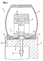
- the emergency running insert 1 is formed in two parts and includes a mounted on the rim 2 stator 5 and a seated on the stator 5 rotor 6, which in turn from annular segment-shaped, hingedly interconnected or composed by means of a clamping system, not shown in the drawing clamping system with each other part elements.
- the stator ring 5 has a slot in the circumferential direction, whose width can be approximately 1 ⁇ 3 of the diameter.
- the stator ring 5 is provided with a meandering bead 7 which extends in the center approximately in the direction of the rotor 6 and is formed together with a corresponding counter recess 8 of the rotor 6 as a guide for the rotor 6.
- the free space formed in the interior of the groove-shaped bead 7 extends as far as the slot-shaped recess of the stator ring 5, so that the air entering through a valve 9 attached to the rim 2 can enter the interior of the pneumatic tire 3 and fills it.
- the rim 2 shown in the drawing is a so-called Flat-bed rim with a cylindrical cross-sectional area and a removable end sealing ring 10.
- the stator 5 has both on its outer side of the rim 2 side facing as well as laterally each a layer of elastic rubber 11, wherein the lateral rubber layer 11 is held away from the rim 2 away outwardly angled circumferential stop surfaces 12 and between these abutment surfaces 12, which can be the same height or, in particular, different heights, and the bead-shaped inner part of the pneumatic tires 3 is clamped.
- the crossbar of the double-T-shaped configuration of the rotor 5 may be provided to facilitate weight with recesses, in particular bores, which, however, need not be uniformly distributed over the circumference.
- thermoplastic rotor 6 has on the outside a tread 13 made of an elastomer, which is held for example by a dovetail connection to the rotor 6. Alternatively, other types of attachment are possible.
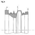
- the abutment surfaces 12 may also act as guide projections with respect to the rotor 6 and may in particular be designed to be circumferential and / or of the same height or, in particular, of different heights, as shown in FIG Fig. 4 is shown.
- Fig. 2 shows an alternative embodiment of a multi-part emergency running insert 1 according to the invention, which is arranged on a rim 2.
- This is a so-called Tiefbettfelge with a non-cylindrical, but provided with a profile rim base.
- the elastic rubber layer 11 is formed in several parts and separated into lateral areas and in a located between the stator ring 5 and the rotor 6 part.
- the part of the rubber layer 11 formed in this respect as an intermediate ring 14 is adapted to the profile of the rim 2, so that even with such a rim 2, a stator provided as standard for cylindrical rim beds can be used.
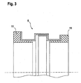
- Fig. 3 shows a stator 5 with it arranged elastic rubber layer 11, wherein both the stator 5 and the elastic rubber layer 11 are each formed in two parts.
- the stator ring 5 is divided in the middle and has two overlapping portions, which are provided in the illustrated embodiment in the region of the circumferential bead, but can also be located elsewhere.
- FIG. 4 Alternative forms of both the stator 5 and the elastic rubber layer 11 are shown, wherein the stator 5 has a total of four circumferential beads of different width, height and shape and the rim 2 facing side of the rubber layer 11 a profiling according to the rim of the in the drawing, not shown rim.
- An intermediate ring is so far not required in such an embodiment.
- Fig. 5 can be provided to prevent twisting or rotating the rotor 6 on the stator ring 5 during normal driving an intermediate element 15, which lifted by the load during emergency operation, the clamping effect generated by the intermediate element is, so that then a free rotation of the rotor 6 on the stator 5 can take place.
- the intermediate element 15 may in particular be provided between the radially aligned regions of the rotor 6 and the stator ring 5, so that it is not provided between the surfaces of the stator ring 5 and rotor 6 which are under radial load during emergency operation.
- the intermediate element 15 may be annular.
- the clearance between the areas of the rotor 6 in contact with the radial surfaces of the bead 7 may be less than the clearance between the radial abutment surfaces 12 and the rotor 6.
- guidance through the abutment surfaces 12 will not occur until the guide is overloaded by the radial surfaces of the bead 7.
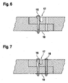
- Fig. 6 shows the connection region of the sub-elements of the rotor 6, wherein two formed as a screw 16 connecting elements may be provided for further stabilization of the overlap connection. This prevents deformation of the overlap during load operation in emergency operation.
- the screw is formed without a threaded sleeve and a screw hole is located within the wedge slope of the not yet tightened wedge-clamping system, whereby the wedge can be made smaller and lighter.
- the two screws 16 extend to better distribution of the tightening force on the ends of the sub-elements of the rotor 6 a common shim 18, which has a larger contact surface than standard washers. An anti-rotation for the shim 18 is thus not required, and the screws 16 may be secured against loosening by the use of self-locking nuts, so that no bonding is required.
Landscapes
- Engineering & Computer Science (AREA)
- Mechanical Engineering (AREA)
- Tires In General (AREA)
- Load-Engaging Elements For Cranes (AREA)
- Spinning Or Twisting Of Yarns (AREA)
- Hooks, Suction Cups, And Attachment By Adhesive Means (AREA)
- Manufacture, Treatment Of Glass Fibers (AREA)
- Soil Working Implements (AREA)
Priority Applications (5)
| Application Number | Priority Date | Filing Date | Title |
|---|---|---|---|
| EP06019127A EP1900550B1 (de) | 2006-09-13 | 2006-09-13 | Segmentierter Notlaufstützring mit Spannmitteln |
| ES06019127T ES2347344T3 (es) | 2006-09-13 | 2006-09-13 | Anillo de apoyo segmentado de marcha de emergencia con medios tensores. |
| DE502006007040T DE502006007040D1 (de) | 2006-09-13 | 2006-09-13 | Segmentierter Notlaufstützring mit Spannmitteln |
| AT06019127T ATE468985T1 (de) | 2006-09-13 | 2006-09-13 | Segmentierter notlaufstützring mit spannmitteln |
| PL06019127T PL1900550T3 (pl) | 2006-09-13 | 2006-09-13 | Dzielony na segmenty awaryjny pierścień oporowy ze środkami mocującymi |
Applications Claiming Priority (1)
| Application Number | Priority Date | Filing Date | Title |
|---|---|---|---|
| EP06019127A EP1900550B1 (de) | 2006-09-13 | 2006-09-13 | Segmentierter Notlaufstützring mit Spannmitteln |
Publications (2)
| Publication Number | Publication Date |
|---|---|
| EP1900550A1 EP1900550A1 (de) | 2008-03-19 |
| EP1900550B1 true EP1900550B1 (de) | 2010-05-26 |
Family
ID=37693852
Family Applications (1)
| Application Number | Title | Priority Date | Filing Date |
|---|---|---|---|
| EP06019127A Not-in-force EP1900550B1 (de) | 2006-09-13 | 2006-09-13 | Segmentierter Notlaufstützring mit Spannmitteln |
Country Status (5)
| Country | Link |
|---|---|
| EP (1) | EP1900550B1 (pl) |
| AT (1) | ATE468985T1 (pl) |
| DE (1) | DE502006007040D1 (pl) |
| ES (1) | ES2347344T3 (pl) |
| PL (1) | PL1900550T3 (pl) |
Families Citing this family (5)
| Publication number | Priority date | Publication date | Assignee | Title |
|---|---|---|---|---|
| CN102785529B (zh) * | 2011-05-18 | 2016-07-06 | 福建省密斯盾轮胎安全装置科技有限公司 | 一种多辋纹汽车轮胎爆胎安全装置及其安装方法 |
| EP2682287A1 (de) * | 2012-07-03 | 2014-01-08 | Europlast-Nycast GmbH | Verspannbarer Notlaufeinsatz |
| CN105459739B (zh) * | 2016-01-13 | 2018-03-20 | 戴广平 | 一种自适应轮辋装配的轮胎内支撑体及其安装方法 |
| CN105667224A (zh) * | 2016-04-11 | 2016-06-15 | 南京工程学院 | 汽车安全轮胎滑轨式内支撑装置及装配方法 |
| CN106274304A (zh) * | 2016-10-19 | 2017-01-04 | 刘双玮 | 一种轮胎防爆装置 |
Family Cites Families (2)
| Publication number | Priority date | Publication date | Assignee | Title |
|---|---|---|---|---|
| US4393911A (en) | 1982-07-26 | 1983-07-19 | Astronics Corporation | Safety liner for tires |
| US4662419A (en) | 1986-02-06 | 1987-05-05 | Astronics Corporation | Beadlock for tubeless tires |
-
2006
- 2006-09-13 ES ES06019127T patent/ES2347344T3/es active Active
- 2006-09-13 DE DE502006007040T patent/DE502006007040D1/de active Active
- 2006-09-13 PL PL06019127T patent/PL1900550T3/pl unknown
- 2006-09-13 EP EP06019127A patent/EP1900550B1/de not_active Not-in-force
- 2006-09-13 AT AT06019127T patent/ATE468985T1/de active
Also Published As
| Publication number | Publication date |
|---|---|
| EP1900550A1 (de) | 2008-03-19 |
| DE502006007040D1 (de) | 2010-07-08 |
| ATE468985T1 (de) | 2010-06-15 |
| PL1900550T3 (pl) | 2011-01-31 |
| ES2347344T3 (es) | 2010-10-28 |
Similar Documents
| Publication | Publication Date | Title |
|---|---|---|
| EP1799469B1 (de) | Fahrzeugrad mit einer felge und einem vollgummireifen | |
| DE2406206B2 (de) | Gummigefedertes schienenrad | |
| EP2882600B1 (de) | Radkonstruktion für ein automobil | |
| EP3509872B1 (de) | Mehrteiliges, gefedertes schienenrad | |
| EP0683735B2 (de) | Notlaufring für ein fahrzeugrad | |
| DE69302665T2 (de) | Verbesserte ringförmige Notlaufeinrichtung | |
| DE60320424T2 (de) | Run-flat-vorrichtung | |
| EP0156009B1 (de) | Fahrzeugrad | |
| DE69805277T2 (de) | Notlaufvorrichtung für auto und verfahren zu seiner montage | |
| EP1900550B1 (de) | Segmentierter Notlaufstützring mit Spannmitteln | |
| WO1998019874A1 (de) | Radkonstruktion, insbesondere für automobile | |
| DE2950718A1 (de) | Luftreifen-radfelgenanordnung | |
| DE3704830A1 (de) | Fahrzeugrad | |
| DE3706903A1 (de) | Fahrzeugrad | |
| DE2339516A1 (de) | Auf eine felge aufziehbarer luftreifen mit plattfahr-eigenschaften | |
| EP1963108A1 (de) | Radnabe mit axialen ausnehmungen zwischen den löchern für radschrauben | |
| DE2937271C2 (pl) | ||
| DE3804505A1 (de) | Luftbereiftes fahrzeugrad | |
| DE2321345A1 (de) | Radfelge | |
| EP1312489B1 (de) | Fahrzeugrad mit einer Felge und einem Vollgummireifen | |
| DE19837712A1 (de) | Fahrzeugrad | |
| DE19943482B4 (de) | Ringförmiger Stützkörper zum Stützen der Lauffläche eines Fahrzeugluftreifens in einem Fahrzeugrad im Notlauf bzw. im Pannenlauf sowie Fahrzeugrad mit einem derartigen Stützkörper | |
| DE19750150A1 (de) | Vorrichtung für plattgefahrene Luftreifen eines Kraftfahrzeugs | |
| EP2682287A1 (de) | Verspannbarer Notlaufeinsatz | |
| DE10001269B4 (de) | Fahrzeugrad für einen schlauchlosen Luftreifen |
Legal Events
| Date | Code | Title | Description |
|---|---|---|---|
| PUAI | Public reference made under article 153(3) epc to a published international application that has entered the european phase |
Free format text: ORIGINAL CODE: 0009012 |
|
| AK | Designated contracting states |
Kind code of ref document: A1 Designated state(s): AT BE BG CH CY CZ DE DK EE ES FI FR GB GR HU IE IS IT LI LT LU LV MC NL PL PT RO SE SI SK TR |
|
| AX | Request for extension of the european patent |
Extension state: AL BA HR MK YU |
|
| 17P | Request for examination filed |
Effective date: 20080905 |
|
| 17Q | First examination report despatched |
Effective date: 20081010 |
|
| AKX | Designation fees paid |
Designated state(s): AT BE BG CH CY CZ DE DK EE ES FI FR GB GR HU IE IS IT LI LT LU LV MC NL PL PT RO SE SI SK TR |
|
| RAP1 | Party data changed (applicant data changed or rights of an application transferred) |
Owner name: EUROPLAST-NYCAST GMBH |
|
| GRAP | Despatch of communication of intention to grant a patent |
Free format text: ORIGINAL CODE: EPIDOSNIGR1 |
|
| GRAS | Grant fee paid |
Free format text: ORIGINAL CODE: EPIDOSNIGR3 |
|
| GRAA | (expected) grant |
Free format text: ORIGINAL CODE: 0009210 |
|
| AK | Designated contracting states |
Kind code of ref document: B1 Designated state(s): AT BE BG CH CY CZ DE DK EE ES FI FR GB GR HU IE IS IT LI LT LU LV MC NL PL PT RO SE SI SK TR |
|
| REG | Reference to a national code |
Ref country code: GB Ref legal event code: FG4D Free format text: NOT ENGLISH |
|
| REG | Reference to a national code |
Ref country code: CH Ref legal event code: EP |
|
| REG | Reference to a national code |
Ref country code: IE Ref legal event code: FG4D Free format text: LANGUAGE OF EP DOCUMENT: GERMAN |
|
| REF | Corresponds to: |
Ref document number: 502006007040 Country of ref document: DE Date of ref document: 20100708 Kind code of ref document: P |
|
| REG | Reference to a national code |
Ref country code: NL Ref legal event code: T3 |
|
| LTIE | Lt: invalidation of european patent or patent extension |
Effective date: 20100526 |
|
| REG | Reference to a national code |
Ref country code: ES Ref legal event code: FG2A Ref document number: 2347344 Country of ref document: ES Kind code of ref document: T3 |
|
| PG25 | Lapsed in a contracting state [announced via postgrant information from national office to epo] |
Ref country code: LT Free format text: LAPSE BECAUSE OF FAILURE TO SUBMIT A TRANSLATION OF THE DESCRIPTION OR TO PAY THE FEE WITHIN THE PRESCRIBED TIME-LIMIT Effective date: 20100526 Ref country code: SE Free format text: LAPSE BECAUSE OF FAILURE TO SUBMIT A TRANSLATION OF THE DESCRIPTION OR TO PAY THE FEE WITHIN THE PRESCRIBED TIME-LIMIT Effective date: 20100526 |
|
| PGFP | Annual fee paid to national office [announced via postgrant information from national office to epo] |
Ref country code: CH Payment date: 20100928 Year of fee payment: 5 Ref country code: ES Payment date: 20100928 Year of fee payment: 5 |
|
| PG25 | Lapsed in a contracting state [announced via postgrant information from national office to epo] |
Ref country code: LV Free format text: LAPSE BECAUSE OF FAILURE TO SUBMIT A TRANSLATION OF THE DESCRIPTION OR TO PAY THE FEE WITHIN THE PRESCRIBED TIME-LIMIT Effective date: 20100526 Ref country code: SI Free format text: LAPSE BECAUSE OF FAILURE TO SUBMIT A TRANSLATION OF THE DESCRIPTION OR TO PAY THE FEE WITHIN THE PRESCRIBED TIME-LIMIT Effective date: 20100526 Ref country code: IS Free format text: LAPSE BECAUSE OF FAILURE TO SUBMIT A TRANSLATION OF THE DESCRIPTION OR TO PAY THE FEE WITHIN THE PRESCRIBED TIME-LIMIT Effective date: 20100926 |
|
| PGFP | Annual fee paid to national office [announced via postgrant information from national office to epo] |
Ref country code: FI Payment date: 20100928 Year of fee payment: 5 |
|
| PG25 | Lapsed in a contracting state [announced via postgrant information from national office to epo] |
Ref country code: GR Free format text: LAPSE BECAUSE OF FAILURE TO SUBMIT A TRANSLATION OF THE DESCRIPTION OR TO PAY THE FEE WITHIN THE PRESCRIBED TIME-LIMIT Effective date: 20100827 Ref country code: CY Free format text: LAPSE BECAUSE OF FAILURE TO SUBMIT A TRANSLATION OF THE DESCRIPTION OR TO PAY THE FEE WITHIN THE PRESCRIBED TIME-LIMIT Effective date: 20100526 |
|
| PGFP | Annual fee paid to national office [announced via postgrant information from national office to epo] |
Ref country code: GB Payment date: 20100928 Year of fee payment: 5 |
|
| REG | Reference to a national code |
Ref country code: IE Ref legal event code: FD4D |
|
| PG25 | Lapsed in a contracting state [announced via postgrant information from national office to epo] |
Ref country code: EE Free format text: LAPSE BECAUSE OF FAILURE TO SUBMIT A TRANSLATION OF THE DESCRIPTION OR TO PAY THE FEE WITHIN THE PRESCRIBED TIME-LIMIT Effective date: 20100526 Ref country code: PT Free format text: LAPSE BECAUSE OF FAILURE TO SUBMIT A TRANSLATION OF THE DESCRIPTION OR TO PAY THE FEE WITHIN THE PRESCRIBED TIME-LIMIT Effective date: 20100927 Ref country code: IE Free format text: LAPSE BECAUSE OF FAILURE TO SUBMIT A TRANSLATION OF THE DESCRIPTION OR TO PAY THE FEE WITHIN THE PRESCRIBED TIME-LIMIT Effective date: 20100526 Ref country code: DK Free format text: LAPSE BECAUSE OF FAILURE TO SUBMIT A TRANSLATION OF THE DESCRIPTION OR TO PAY THE FEE WITHIN THE PRESCRIBED TIME-LIMIT Effective date: 20100526 |
|
| PGFP | Annual fee paid to national office [announced via postgrant information from national office to epo] |
Ref country code: FR Payment date: 20101013 Year of fee payment: 5 Ref country code: NL Payment date: 20100928 Year of fee payment: 5 |
|
| REG | Reference to a national code |
Ref country code: PL Ref legal event code: T3 |
|
| PG25 | Lapsed in a contracting state [announced via postgrant information from national office to epo] |
Ref country code: RO Free format text: LAPSE BECAUSE OF FAILURE TO SUBMIT A TRANSLATION OF THE DESCRIPTION OR TO PAY THE FEE WITHIN THE PRESCRIBED TIME-LIMIT Effective date: 20100526 Ref country code: SK Free format text: LAPSE BECAUSE OF FAILURE TO SUBMIT A TRANSLATION OF THE DESCRIPTION OR TO PAY THE FEE WITHIN THE PRESCRIBED TIME-LIMIT Effective date: 20100526 Ref country code: CZ Free format text: LAPSE BECAUSE OF FAILURE TO SUBMIT A TRANSLATION OF THE DESCRIPTION OR TO PAY THE FEE WITHIN THE PRESCRIBED TIME-LIMIT Effective date: 20100526 |
|
| PGFP | Annual fee paid to national office [announced via postgrant information from national office to epo] |
Ref country code: PL Payment date: 20100921 Year of fee payment: 5 |
|
| BERE | Be: lapsed |
Owner name: EUROPLAST-NYCAST G.M.B.H. Effective date: 20100930 |
|
| PGFP | Annual fee paid to national office [announced via postgrant information from national office to epo] |
Ref country code: IT Payment date: 20100925 Year of fee payment: 5 |
|
| PLBE | No opposition filed within time limit |
Free format text: ORIGINAL CODE: 0009261 |
|
| STAA | Information on the status of an ep patent application or granted ep patent |
Free format text: STATUS: NO OPPOSITION FILED WITHIN TIME LIMIT |
|
| PG25 | Lapsed in a contracting state [announced via postgrant information from national office to epo] |
Ref country code: MC Free format text: LAPSE BECAUSE OF NON-PAYMENT OF DUE FEES Effective date: 20100930 |
|
| 26N | No opposition filed |
Effective date: 20110301 |
|
| REG | Reference to a national code |
Ref country code: DE Ref legal event code: R097 Ref document number: 502006007040 Country of ref document: DE Effective date: 20110228 |
|
| PG25 | Lapsed in a contracting state [announced via postgrant information from national office to epo] |
Ref country code: BE Free format text: LAPSE BECAUSE OF NON-PAYMENT OF DUE FEES Effective date: 20100930 |
|
| REG | Reference to a national code |
Ref country code: NL Ref legal event code: V1 Effective date: 20120401 |
|
| REG | Reference to a national code |
Ref country code: CH Ref legal event code: PL |
|
| GBPC | Gb: european patent ceased through non-payment of renewal fee |
Effective date: 20110913 |
|
| PG25 | Lapsed in a contracting state [announced via postgrant information from national office to epo] |
Ref country code: IT Free format text: LAPSE BECAUSE OF NON-PAYMENT OF DUE FEES Effective date: 20110913 Ref country code: FI Free format text: LAPSE BECAUSE OF NON-PAYMENT OF DUE FEES Effective date: 20110913 |
|
| REG | Reference to a national code |
Ref country code: FR Ref legal event code: ST Effective date: 20120531 |
|
| PG25 | Lapsed in a contracting state [announced via postgrant information from national office to epo] |
Ref country code: NL Free format text: LAPSE BECAUSE OF NON-PAYMENT OF DUE FEES Effective date: 20120401 Ref country code: LI Free format text: LAPSE BECAUSE OF NON-PAYMENT OF DUE FEES Effective date: 20110930 Ref country code: CH Free format text: LAPSE BECAUSE OF NON-PAYMENT OF DUE FEES Effective date: 20110930 |
|
| PG25 | Lapsed in a contracting state [announced via postgrant information from national office to epo] |
Ref country code: FR Free format text: LAPSE BECAUSE OF NON-PAYMENT OF DUE FEES Effective date: 20110930 Ref country code: GB Free format text: LAPSE BECAUSE OF NON-PAYMENT OF DUE FEES Effective date: 20110913 |
|
| PG25 | Lapsed in a contracting state [announced via postgrant information from national office to epo] |
Ref country code: HU Free format text: LAPSE BECAUSE OF FAILURE TO SUBMIT A TRANSLATION OF THE DESCRIPTION OR TO PAY THE FEE WITHIN THE PRESCRIBED TIME-LIMIT Effective date: 20101127 Ref country code: LU Free format text: LAPSE BECAUSE OF NON-PAYMENT OF DUE FEES Effective date: 20100913 Ref country code: BG Free format text: LAPSE BECAUSE OF FAILURE TO SUBMIT A TRANSLATION OF THE DESCRIPTION OR TO PAY THE FEE WITHIN THE PRESCRIBED TIME-LIMIT Effective date: 20100526 |
|
| PG25 | Lapsed in a contracting state [announced via postgrant information from national office to epo] |
Ref country code: PL Free format text: LAPSE BECAUSE OF NON-PAYMENT OF DUE FEES Effective date: 20110913 |
|
| REG | Reference to a national code |
Ref country code: AT Ref legal event code: MM01 Ref document number: 468985 Country of ref document: AT Kind code of ref document: T Effective date: 20110913 |
|
| REG | Reference to a national code |
Ref country code: PL Ref legal event code: LAPE |
|
| PG25 | Lapsed in a contracting state [announced via postgrant information from national office to epo] |
Ref country code: TR Free format text: LAPSE BECAUSE OF NON-PAYMENT OF DUE FEES Effective date: 20110913 Ref country code: AT Free format text: LAPSE BECAUSE OF NON-PAYMENT OF DUE FEES Effective date: 20110913 |
|
| PGFP | Annual fee paid to national office [announced via postgrant information from national office to epo] |
Ref country code: DE Payment date: 20121011 Year of fee payment: 7 Ref country code: TR Payment date: 20100913 Year of fee payment: 5 |
|
| PG25 | Lapsed in a contracting state [announced via postgrant information from national office to epo] |
Ref country code: BG Free format text: LAPSE BECAUSE OF FAILURE TO SUBMIT A TRANSLATION OF THE DESCRIPTION OR TO PAY THE FEE WITHIN THE PRESCRIBED TIME-LIMIT Effective date: 20100826 |
|
| REG | Reference to a national code |
Ref country code: ES Ref legal event code: FD2A Effective date: 20131030 |
|
| PG25 | Lapsed in a contracting state [announced via postgrant information from national office to epo] |
Ref country code: ES Free format text: LAPSE BECAUSE OF NON-PAYMENT OF DUE FEES Effective date: 20110914 |
|
| REG | Reference to a national code |
Ref country code: DE Ref legal event code: R119 Ref document number: 502006007040 Country of ref document: DE Effective date: 20140401 |
|
| PG25 | Lapsed in a contracting state [announced via postgrant information from national office to epo] |
Ref country code: DE Free format text: LAPSE BECAUSE OF NON-PAYMENT OF DUE FEES Effective date: 20140401 |