EP1900526A1 - Cloth feed control device of a cleaning device for printing press cylinders - Google Patents
Cloth feed control device of a cleaning device for printing press cylinders Download PDFInfo
- Publication number
- EP1900526A1 EP1900526A1 EP07114813A EP07114813A EP1900526A1 EP 1900526 A1 EP1900526 A1 EP 1900526A1 EP 07114813 A EP07114813 A EP 07114813A EP 07114813 A EP07114813 A EP 07114813A EP 1900526 A1 EP1900526 A1 EP 1900526A1
- Authority
- EP
- European Patent Office
- Prior art keywords
- cloth
- cleaning
- increments
- roll
- feed
- Prior art date
- Legal status (The legal status is an assumption and is not a legal conclusion. Google has not performed a legal analysis and makes no representation as to the accuracy of the status listed.)
- Granted
Links
- 239000004744 fabric Substances 0.000 title claims abstract description 199
- 238000004140 cleaning Methods 0.000 title claims abstract description 114
- 238000007639 printing Methods 0.000 title claims abstract description 39
- 238000000034 method Methods 0.000 claims abstract description 8
- 230000015654 memory Effects 0.000 claims description 11
- 230000002093 peripheral effect Effects 0.000 claims description 8
- 238000009825 accumulation Methods 0.000 claims description 2
- 230000008859 change Effects 0.000 abstract description 2
- 230000008569 process Effects 0.000 description 5
- 230000009467 reduction Effects 0.000 description 3
- 238000005406 washing Methods 0.000 description 3
- 230000008901 benefit Effects 0.000 description 2
- 230000001419 dependent effect Effects 0.000 description 2
- 239000007788 liquid Substances 0.000 description 2
- 238000007645 offset printing Methods 0.000 description 2
- 239000012459 cleaning agent Substances 0.000 description 1
- 238000011109 contamination Methods 0.000 description 1
- 230000008878 coupling Effects 0.000 description 1
- 238000010168 coupling process Methods 0.000 description 1
- 238000005859 coupling reaction Methods 0.000 description 1
- 230000001186 cumulative effect Effects 0.000 description 1
- 230000003247 decreasing effect Effects 0.000 description 1
- 230000000694 effects Effects 0.000 description 1
- 230000006870 function Effects 0.000 description 1
- 238000009434 installation Methods 0.000 description 1
- 230000007257 malfunction Effects 0.000 description 1
- 230000003287 optical effect Effects 0.000 description 1
- 239000007921 spray Substances 0.000 description 1
- 238000005507 spraying Methods 0.000 description 1
- XLYOFNOQVPJJNP-UHFFFAOYSA-N water Substances O XLYOFNOQVPJJNP-UHFFFAOYSA-N 0.000 description 1
- 238000004804 winding Methods 0.000 description 1
Images

Classifications
-
- B—PERFORMING OPERATIONS; TRANSPORTING
- B41—PRINTING; LINING MACHINES; TYPEWRITERS; STAMPS
- B41F—PRINTING MACHINES OR PRESSES
- B41F35/00—Cleaning arrangements or devices
Definitions
- the invention relates to a cloth feed control device of a cleaning device for printing press cylinder according to the preamble of claim 1.
- the invention relates to a cleaning device having such a cloth feed control device.
- the invention relates to a control system, which contains two or more cloth feed control means for corresponding two or more cleaning devices for printing press cylinders in a printing press, for. B. in an offset printing machine.
- the cleaning devices are designed for the rotatable mounting of two cloth rolls, of which one roll of cloth is a cleaning cloth roll, and the other cloth roll is a dirty cloth roll.
- the dirt cloth roll is from a drive automatically stepwise drivable, z. B. from a pneumatic cylinder to transfer the cleaning cloth step by step to a predetermined Tuchvorschuband of the cleaning cloth roll on the dirty cloth roll.
- the cleaning cloth is transported during a cleaning process at least once, preferably several times by the predetermined cloth feed length, so that in each case a clean cloth section is applied to the cylinder circumference of the press cylinder to be cleaned.
- the cleaning cloth may be dry or damp.
- the cleaning cloth may already be damp on the cleaning cloth roll or moistened only on the way to the dirty cloth roller at a location which is in front of the point at which the cleaning cloth is pressed by means of a pressing element to the cylinder circumference.
- a washing device for a printing machine contains an ultrasonic sensor for detecting the cloth level of a cleaning cloth roll. This is to determine when only a predetermined short amount of residual cloth on the cleaning cloth roll is present, which would not be sufficient for a new printing operation. This eliminates the need to stop printing because the cleaning cloth will not last until the end of the printing process.
- the problem to be solved a cleaning device and in particular their control device for the cleaning of printing press cylinders in such a way that a more efficient use of the cleaning cloth is possible.
- a cleaning device which is provided with a cloth feed control device according to the invention.
- the invention also relates to a control system which includes two or more cloth feed control means for correspondingly two or more press cylinder cleaners.
- the invention also relates to an installation which contains two or more cleaning devices for cleaning printing press cylinders and a corresponding number of cloth feed control devices.
- a non-contact sensor preferably an ultrasonic sensor, scans the peripheral surface of one of the two cloth rolls, preferably the cleaning cloth roll, and generates, depending on the detected distance, a signal corresponding to the radius of the cloth roll, in particular an electric current or, alternatively, a voltage level.
- the sensor is preferably designed such that changes in distance result in linear changes in the signal value.
- the cloth roll circumference is automatically calculated.
- the calculated cloth roll circumference is set in relation to a defined cloth feed length (cloth feed length set value) by means of a number of increments defined in the total circumference of the cloth roll.
- the defined cloth feed length is the cloth feed length by which the cloth is to be transported on each feed step of the cleaning cloth roll in the direction of the dirty cloth roll on.
- the value to be determined for the number of increments to be returned which for the Feed of the defined cloth feed length are rounded in the case of decimal values, rounded up, for example, from a decimal value of 0.5 to the next integer, otherwise rounded to the nearest integer. If the active cloth feed has reached the determined value of the increments, the cloth feed is automatically ended, eg. B. by deactivating a valve through which a pneumatic drive compressed air can be supplied.
- the number of increments taken in a cloth advancement step is added and stored in a sum memory.
- the stored number of increments can be used for various purposes, for example, to automatically calculate the used cloth length or remaining on the cleaning cloth roll cloth length and / or to generate a signal when there is only a predetermined minimum residual length of cloth on the cleaning cloth role.
- a particularly advantageous use of the summed values of traveled increments stored in the summation memory is to automatically calculate an average value from the summation values of two or more cleaning devices of a printing machine and to determine this average value as a setpoint for all cleaning devices within the same printing machine. For all cleaning devices, the difference between the stored increments stored in the total memory and the desired value is determined and this difference is also stored.
- the number of increments to be returned by increasing or decreasing Reduction is adjusted so that the total number of recirculated increments of the various purifiers aligns again or the total number of increments taken back becomes the same across all purifiers. In this case, it must be ensured that a reduction in the number of increments during a cloth feed does not fall below a defined minimum value of increments, to ensure that always enough fresh cleaning cloth is placed on the press cylinder to be cleaned.
- the cleaning devices are commonly referred to as washing bars because they extend in a beam-like manner across the printing press for substantially the same length as the printing press cylinder to be cleaned.
- the invention dispenses with previously required mechanical parts such.
- no malfunctions due to contamination can occur in the invention since all parts required according to the invention can be accommodated in a protected space.
- the known parts have the disadvantage that they can be bent or broken on the printing machine by external influence. These disadvantages are also avoided by the invention.
- Fig. 1 shows schematically two cloth feed control devices 2-1 and 2-2 for an equal number of cleaning devices 4-1 and 4-2 for cleaning accordingly also two printing press cylinders 6-1 and 6-2 of a printing machine, for. B. an offset printing machine. Since both cloth feed control devices 2-1 and 2-2 as well as the two cleaning devices 4-1 and 4-2 can each be designed the same, in the following only one Cloth feed control device 2-1 described for a cleaning device 4-1, as far as nothing else is mentioned below.
- the cleaning device 4-1 extends substantially the entire length of the printing press cylinder 6-1 to be cleaned by it. It is designed for the rotatable mounting of two cloth rolls, one of which is a cleaning cloth roll 8 and the other is a dirty cloth roll 10.
- the dirty cloth roll 10 is gradually rotated by an automatic driving device 11 to transport a predetermined cloth feeding length from the cleaning cloth roll 8 to the dirty cloth roll 10, respectively. In this case, the roll diameter of the two cloth rolls 8 and 10 changes.
- a pressing member 16 for pressing the cleaning cloth 12 to be cleaned to the printing press cylinder 6-1.
- a liquid spray device 18 for spraying the cleaning cloth 12 with liquid, for. As water and / or a cleaning agent may be provided.
- the cleaning cloth 12 is applied at least once or more times by means of the pressing member 16 and / or by moving the entire cleaning device 4-1 to the cylinder peripheral surface of the printing press cylinder 6-1 and then again distanced therefrom. After each application to the printing press cylinder (or according to another embodiment during the application), the cleaning cloth is transported in one step by the predetermined cloth feed length on.
- the drive device 11 may be formed in various ways. It may for example contain an electric stepper motor or a pneumatic drive 20 (piston-cylinder unit), the piston of a valve 22 controlled axially reciprocable and drives via a drive connection 24 a freewheel 26, which with a cloth roll core 28 of Dirt roll 10 is drivingly connected.
- a pneumatic drive 20 pneumatic drive 20 (piston-cylinder unit)
- the piston of a valve 22 controlled axially reciprocable and drives via a drive connection 24 a freewheel 26, which with a cloth roll core 28 of Dirt roll 10 is drivingly connected.
- the cloth feed control device 2-1 includes a non-contact distance sensor 30.
- the distance sensor 30 is for generating signals, preferably analog signals, in the form of an electric current value or an electric Voltage value formed depending on the respective radial distance of the distance sensor 30 from the outer periphery of one of the two cloth rolls, for example, the cleaning cloth roll 8 (or the dirty cloth roll 10).
- the signals of the distance sensor 30 change linearly in proportion to changes in the radial distance of the outer periphery of the cloth roll from the distance sensor 30.
- the distance sensor 30 is positioned at a predetermined distance 32 from the rotation axis 34 of the cleaning cloth roll 8 radially to the rotation axis 34, so that the analog signals of the distance sensor 30th correspond to the respective radius of the cloth roll, although the distance sensor 30 actually detects only its distance to the cloth roll peripheral surface.
- the distance sensor 30 is preferably an ultrasonic sensor whose sound transit time from the distance sensor 30 to the cloth roll peripheral surface and back again is a measure of the distance.
- FIG. 1 schematically shows the transmitted ultrasonic beam 36 and the reflected ultrasonic beam 38.
- the cloth feed control device 2-1 contains a control part 40 which is connected to the distance sensor 30 and calculates the respective circumferential size of this cleaning cloth roll 8 from its analog signal, which corresponds to the radius of the detected clean cloth roll 8.
- a cloth feed length set value 42 is stored or stored, which indicates how large the cloth feed length should be at a feed step.
- a predetermined number of increments for a 360 ° rotation of the cloth roll 8 are stored. In other words, the circumference of the roll of cloths 8 of 360 ° is divided into equally large rotation angle increments.
- the control part 40 is designed to calculate how many increments the cloth roll 8 has to be rotated in order to transport the cleaning cloth at the calculated peripheral size of the cloth roll 8 by a cloth feed length corresponding to the desired value by means of the drive device 11. For this purpose, the control part 40 is designed to generate a setpoint value corresponding to the calculated increments for the drive device 11.
- the control part 40 is preferably provided with at least one processor for performing the calculations and with a data memory.
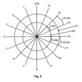
- Fig. 2 shows schematically an end view of one of the two cloth rolls, for example, the cleaning cloth roll 8.
- Their front side is divided about its axis of rotation 34 over 360 ° in said predetermined number of equal increments.
- 360 increments or 720 increments may be provided.
- the cloth feed length which is transported by an increment upon rotation of the cloth roll 8, is dependent on the outer cloth roll diameter or radius. From the measured radius, the control part 42 calculates the cloth roll circumference.
- the cloth roll circumference U1 is equal to 10 mm between two increments.
- the cloth length portion between two increments is only 5 mm. It can be seen that for a desired cloth feed length (setpoint) of 10 mm, the cleaning cloth roll 8 at the large diameter U1 needs to be rotated only by one increment, while it has to be further rotated by 2 increments at the small diameter U2 to the same Unwind cloth feed length of the cloth roll 8. The same function can be achieved if the analog distance sensor 30 does not detect the cleaning cloth roll 8 but the dirty cloth roll 10.
- decimal amounts may result.
- the control part 40 may be designed such that it always rounds up these decimal amounts or always rounds them off or is designed such that it rounds up to the next whole number from a predetermined decimal value of, for example, 0.5, otherwise rounds off to the next whole number.
- FIG. 1 shows an encoder 44 which has an encoder disk 46 provided with increment markings 45 (lines, holes, etc.) and an encoder sensor 47 for detecting the increment markings 45.
- the encoder sensor 47 is connected to the control part 40 so as to supply an electrical signal every time an increment mark 45 is detected.
- the incremental slide 46 is connected to the dirty cloth roll 10 (or the cleaning cloth roll 8) via a connecting member 48 for common rotation.
- the connecting element is z. B. connected to a coupling element, which is connected to the winding core 28 of the Schmutzruchrolle 10 (or the cleaning cloth roll 8) or connectable.
- the increment markers 45 may be provided on another encoder instead of an encoder disk 46, which is connected to the cloth roll 10 or 8 directly or via a reduction or translation.
- the control part 40 preferably includes a totalizer 50 for counting the total number of increments or increment marks 45 around which the dirty cloth roll 10 and thus also the clean cloth roll 8 has been rotated for all initial advances of cloth advance lengths performed since a first start.
- the total number of already rotated increments can be used for different purposes. It is a measure of how much cleaning cloth has already been wrapped by the cleaning cloth roll 8 on the dirty cloth roll 10 and also how much remaining cloth length is still present on the cleaning cloth roll. There is the advantageous possibility of automatically displaying the total number of increments or a length measure corresponding to this total number, either the towel roll already unwound from the cloth length or remaining on it remaining cloth length.
- the minimum remaining towel length can be important if it is still sufficient to carry out all cleaning operations during a printing process, or a new cleaning cloth roll 8 is required in order to perform a printing process without interruption.
- the analog distance sensor 30 and / or the encoder 44 are preferably arranged on the cleaning device 4-1 or 4-2 and form together with this a structural unit which can be inserted into a printing press.
- the control part 40 can also be arranged on the cleaning device, but is preferably arranged separately from it.
- a printing machine usually includes a plurality of cleaning devices 4-1, 4-2, etc. (washing bars) for cleaning a plurality of printing press cylinders 6-1, 6-2, etc. It is desirable to have cleaning cloths 12 in all cleaning devices 4-1, 4-2, etc at the same time so that the printing operation does not have to be interrupted several times.
- the invention offers the possibility of comparing the total number of increments counted and stored since a first start of cloth feeds with all cleaning devices 4-1 and 4-2 and making changes to the setpoint control signal for the drive device 11 such that different total numbers of increments be compensated again.
- the control parts 40 of all cleaning devices 4-1 and 4-2 are designed to generate a difference signal from the actual value of the total number of counted increments of their sum counter 50 and from an increment total number setpoint.
- the increment total number target value is the average value of a plurality of cleaning devices 4-1 and 4-2 in a printing machine obtained by adding the total number of counted increments of the sum counters 50 from all the cleaning devices 4-1 and 4-2 and then dividing the total number Addition value by the number of cleaning devices 4-1 and 4-2 results.
- This calculation may preferably be performed automatically or by a person who reads the total number of counted increments of the totalizers 50 on a cumulative counter display or from a print-out, then adds the addition value by the number of cleaners, and then enters the thus calculated increment total number setpoint in the control parts 40.
- the control parts 40 of all the cleaning devices 4-1 and 4-2 are designed to generate a corrected control signal target value which, instead of the original target value for the predetermined cloth feed stroke, takes effect if the difference signal deviates from a predetermined permissible difference value. This difference value can be 0 or have a different value.
- a controller combination which comprises two or more cloth feed control devices 2-1 and 2-2 for respectively two or more cleaning devices 4-1, 4-2, etc. in a printing machine, and which for automatic calculation and application of the increment total number setpoint is formed.
- the controller combination includes a comparison part 60 which is connected to the control parts 40 of all the cleaning devices 4-1, 4-2, etc. and has a summation memory 62.
- the comparing part 60 includes a calculator 64 which adds the total number of increments of the sum counters 50 from all the control parts 40 to a total in which accumulation memory 62 stores, and then stores the stored total number of increments counted by the number of all the control parts 40 which corresponds to the number of Cleaning devices 4-1, 4-2, etc. corresponds, divides and thereby an average value, which is passed from the comparison part 60 in the form of the increment total number set value to all control parts 40.
- the control parts 40 form therefrom the difference signal between this increment total number set value and the actual value of the total number of counted increments of their summation counter 50.
- the corrected control signal setpoint is limited to a minimum value, in order to ensure that the cleaning cloth 12 in each according to a feed step provided for a cleaning program is actually further transported by a predetermined minimum number of increments. This ensures that at each provided according to the cleaning program feed step actually a cloth feed takes place and thereby a fresh tissue section is applied to the printing press cylinder 6-1 and 6-2, even if the calculated difference signal results in a corrected control signal setpoint at which no cloth feed would take place at the next feed step.
Abstract
Description
Die Erfindung betrifft eine Tuchvorschub-Steuereinrichtung einer Reinigungsvorrichtung für Druckmaschinenzylinder gemäß dem Oberbegriff von Anspruch 1.The invention relates to a cloth feed control device of a cleaning device for printing press cylinder according to the preamble of
Ferner betrifft die Erfindung eine Reinigungsvorrichtung, welche eine solche Tuchvorschub-Steuereinrichtung aufweist.Furthermore, the invention relates to a cleaning device having such a cloth feed control device.
Auch betrifft die Erfindung eine Steueranlage, welche zwei oder mehr Tuchvorschub-Steuereinrichtungen für entsprechend zwei oder mehr Reinigungsvorrichtungen für Druckmaschinenzylinder in einer Druckmaschine enthält, z. B. in einer Offset-Druckmaschine.Also, the invention relates to a control system, which contains two or more cloth feed control means for corresponding two or more cleaning devices for printing press cylinders in a printing press, for. B. in an offset printing machine.
Die Reinigungsvorrichtungen sind zur drehbaren Lagerung von zwei Tuchrollen ausgebildet, von welchen eine Tuchrolle eine Saubertuchrolle, und die andere Tuchrolle eine Schmutztuchrolle ist. Die Schmutztuchrolle ist von einem Antrieb automatisch schrittweise antreibbar, z. B. von einem Pneumatik-Zylinder, um das Reinigungstuch schrittweise um jeweils eine vorbestimmte Tuchvorschublänge von der Saubertuchrolle auf die Schmutztuchrolle zu übertragen. Das Reinigungstuch wird während eines Reinigungsvorgangs mindestens einmal, vorzugsweise mehrmals um jeweils die vorbestimmte Tuchvorschublänge weiter transportiert, sodass jeweils ein sauberer Tuchabschnitt an den Zylinderumfang des zu reinigenden Druckmaschinenzylinders angelegt wird. Das Reinigungstuch kann trocken oder feucht sein. Das Reinigungstuch kann bereits auf der Saubertuchrolle feucht sein oder erst auf dem Weg zur Schmutztuchrolle an einer Stelle befeuchtet werden, welche vor der Stelle liegt, an welcher das Reinigungstuch mittels eines Andrückelements an den Zylinderumfang andrückbar ist.The cleaning devices are designed for the rotatable mounting of two cloth rolls, of which one roll of cloth is a cleaning cloth roll, and the other cloth roll is a dirty cloth roll. The dirt cloth roll is from a drive automatically stepwise drivable, z. B. from a pneumatic cylinder to transfer the cleaning cloth step by step to a predetermined Tuchvorschublänge of the cleaning cloth roll on the dirty cloth roll. The cleaning cloth is transported during a cleaning process at least once, preferably several times by the predetermined cloth feed length, so that in each case a clean cloth section is applied to the cylinder circumference of the press cylinder to be cleaned. The cleaning cloth may be dry or damp. The cleaning cloth may already be damp on the cleaning cloth roll or moistened only on the way to the dirty cloth roller at a location which is in front of the point at which the cleaning cloth is pressed by means of a pressing element to the cylinder circumference.
Aus der
Eine von mehreren Ausführungsformen einer Reinigungsvorrichtung für Druckmaschinenzylinder ist aus der
Eine automatische Zylinderreinigungsvorrichtung für Druckmaschinen ist auch aus der
Durch die Erfindung soll die Aufgabe gelöst werden, eine Reinigungsvorrichtung und insbesondere ihre Steuereinrichtung für die Reinigung von Druckmaschinenzylindern derart auszubilden, dass eine effizientere Nutzung des Reinigungstuchs möglich ist.By the invention, the problem to be solved, a cleaning device and in particular their control device for the cleaning of printing press cylinders in such a way that a more efficient use of the cleaning cloth is possible.
Diese Aufgabe wird gemäß der Erfindung durch die Merkmale von Anspruch 1 gelöst.This object is achieved according to the invention by the features of
Weitere Merkmale der Erfindung sind in den Unteransprüchen enthalten.Further features of the invention are contained in the subclaims.
Ferner wird die Aufgabe gemäß der Erfindung durch eine Reinigungsvorrichtung gelöst, welche mit einer Tuchvorschub-Steuereinrichtung nach der Erfindung versehen ist.Furthermore, the object is achieved according to the invention by a cleaning device, which is provided with a cloth feed control device according to the invention.
Die Erfindung betrifft auch eine Steueranlage, welche zwei oder mehr Tuchvorschub-Steuereinrichtungen für entsprechend zwei oder mehr Reinigungsvorrichtungen für Druckmaschinenzylinder enthält.The invention also relates to a control system which includes two or more cloth feed control means for correspondingly two or more press cylinder cleaners.
Entsprechend betrifft die Erfindung auch eine Anlage, welche zwei oder mehr Reinigungsvorrichtungen zur Reinigung von Druckmaschinenzylindern und eine entsprechende Anzahl von Tuchvorschub-Steuereinrichtungen enthält.Accordingly, the invention also relates to an installation which contains two or more cleaning devices for cleaning printing press cylinders and a corresponding number of cloth feed control devices.
Die Erfindung beinhaltet mehrere Merkmale, die einzeln und in Kombination vorteilhaft verwendbar sind:The invention includes several features that can be used individually and in combination to advantage:
Ein berührungsloser Sensor, vorzugsweise ein Ultraschallsensor, tastet die Umfangsfläche einer der beiden Tuchrollen, vorzugsweise der Saubertuchrolle, ab und erzeugt in Abhängigkeit von dem detektierten Abstand ein dem Radius der Tuchrolle entsprechendes Signal, insbesondere eine elektrische Stromstärke oder alternativ eine Spannungshöhe. Der Sensor ist vorzugsweise derart ausgebildet, dass Abstandsänderungen lineare Änderungen des Signalwerts zur Folge haben. Mit dem somit ermittelten Radius wird der Tuchrollenumfang automatisch errechnet. Der errechnete Tuchrollenumfang wird in Relation zu einer definierten Tuchvorschublänge (Tuchvorschublänge-Sollwert) gesetzt mittels einer den Gesamtumfang der Tuchrolle definierten Anzahl von Inkrementen. Die definierte Tuchvorschublänge ist die Tuchvorschublänge, um welche das Tuch bei jedem Vorschubschritt von der Saubertuchrolle in Richtung zur Schmutztuchrolle weiter transportiert werden soll. Der zu ermittelnde Wert für die Anzahl der zurück zu legenden Inkremente, die für den Vorschub der definierten Tuchvorschublänge erforderlich sind, wird im Fall von Dezimalwerten gerundet, beispielsweise ab einem Dezimalwert von 0,5 zur nächsten ganzen Zahl aufgerundet, ansonsten zur nächsten ganzen Zahl abgerundet. Wenn der aktive Tuchvorschub den ermittelten Wert der Inkremente erreicht hat, wird der Tuchvorschub automatisch beendet, z. B. durch Deaktivierung eines Ventils, durch welches einem pneumatischen Antrieb Druckluft zuführbar ist.A non-contact sensor, preferably an ultrasonic sensor, scans the peripheral surface of one of the two cloth rolls, preferably the cleaning cloth roll, and generates, depending on the detected distance, a signal corresponding to the radius of the cloth roll, in particular an electric current or, alternatively, a voltage level. The sensor is preferably designed such that changes in distance result in linear changes in the signal value. With the radius thus determined, the cloth roll circumference is automatically calculated. The calculated cloth roll circumference is set in relation to a defined cloth feed length (cloth feed length set value) by means of a number of increments defined in the total circumference of the cloth roll. The defined cloth feed length is the cloth feed length by which the cloth is to be transported on each feed step of the cleaning cloth roll in the direction of the dirty cloth roll on. The value to be determined for the number of increments to be returned, which for the Feed of the defined cloth feed length are rounded in the case of decimal values, rounded up, for example, from a decimal value of 0.5 to the next integer, otherwise rounded to the nearest integer. If the active cloth feed has reached the determined value of the increments, the cloth feed is automatically ended, eg. B. by deactivating a valve through which a pneumatic drive compressed air can be supplied.
Gemäß einem weiteren Gedanken der Erfindung werden die Anzahl der bei einem Tuchvorschubschritt zurückgelegten Inkremente addiert und in einem Summenspeicher gespeichert. Die gespeicherte Anzahl von Inkrementen kann für verschiedene Zwecke verwendet werden, beispielsweise zur automatischen Berechnung der verbrauchten Tuchlänge oder der auf der Saubertuchrolle noch vorhandenen Tuchrestlänge und/oder zur Erzeugung eines Signals, wenn sich auf der Saubertuchrolle nur noch eine vorbestimmte Mindestrestlänge an Tuch befindet.According to another aspect of the invention, the number of increments taken in a cloth advancement step is added and stored in a sum memory. The stored number of increments can be used for various purposes, for example, to automatically calculate the used cloth length or remaining on the cleaning cloth roll cloth length and / or to generate a signal when there is only a predetermined minimum residual length of cloth on the cleaning cloth role.
Eine besonders vorteilhafte Verwendung der im Summenspeicher gespeicherten Summenwerte von zurückgelegten Inkrementen besteht darin, aus den Summenwerten von zwei oder mehreren Reinigungsvorrichtungen einer Druckmaschine automatisch einen Durchschnittswert zu errechnen und diesen Durchschnittswert als Sollwert für alle Reinigungsvorrichtungen innerhalb der gleichen Druckmaschine zu bestimmen. Für alle Reinigungsvorrichtungen wird die Differenz der zurückgelegten, im Summenspeicher gespeicherten Inkremente zu dem Sollwert ermittelt und diese Differenz ebenfalls gespeichert. Bei Abweichungen der Differenz von einem definierten Grenzwert an einer Reinigungsvorrichtung nach oben oder nach unten werden bei mindestens dem der nächsten Tuchvorschübe desselben Reinigungsvorgangs oder des nächsten Reinigungsvorgangs von der vom Tuchrollendurchmesser abhängigen, zu ermittelnden Anzahl von Inkrementen die Anzahl der zurück zu legenden Inkremente durch Erhöhung oder Reduzierung dahingehend angepasst, dass sich die Gesamtzahl der zurückgelegten Inkremente der verschiedenen Reinigungseinrichtungen wieder aneinander angleicht oder die Gesamtzahl der zurückgelegten Inkremente bei allen Reinigungsvorrichtungen wieder gleich wird. Hierbei muss sichergestellt werden, dass bei einer Reduzierung der Anzahl von Inkrementen bei einem Tuchvorschub ein definierter Mindestwert von Inkrementen nicht unterschritten wird, damit sichergestellt ist, dass immer genügend frisches Reinigungstuch an den zu reinigenden Druckmaschinenzylinder angestellt wird.A particularly advantageous use of the summed values of traveled increments stored in the summation memory is to automatically calculate an average value from the summation values of two or more cleaning devices of a printing machine and to determine this average value as a setpoint for all cleaning devices within the same printing machine. For all cleaning devices, the difference between the stored increments stored in the total memory and the desired value is determined and this difference is also stored. In case of deviations of the difference from a defined limit value on a cleaning device upwards or downwards, at least the next cloth feeds of the same cleaning operation or the next cleaning operation of the number of increments to be determined dependent on the roll diameter, the number of increments to be returned by increasing or decreasing Reduction is adjusted so that the total number of recirculated increments of the various purifiers aligns again or the total number of increments taken back becomes the same across all purifiers. In this case, it must be ensured that a reduction in the number of increments during a cloth feed does not fall below a defined minimum value of increments, to ensure that always enough fresh cleaning cloth is placed on the press cylinder to be cleaned.
Die Reinigungsvorrichtungen werden üblicherweise als Waschbalken bezeichnet, da sie sich balkenartig quer durch die Druckmaschine im Wesentlichen über die gleiche Länge wie der zu reinigende Druckmaschinenzylinder erstrecken.The cleaning devices are commonly referred to as washing bars because they extend in a beam-like manner across the printing press for substantially the same length as the printing press cylinder to be cleaned.
Vorteile der Erfindung: Die Erfindung verzichtet auf bisher benötigte mechanische Teile wie z. B. Tuchende-Begrenzungshebel, Tuch-Tastlöffel oder Schaltrad mit einer Antriebsrolle. Im Gegensatz zu diesen Teilen können bei der Erfindung keine Funktionsstörungen in Folge von Verschmutzung auftreten, da alle gemäß der Erfindung erforderlichen Teile in einem geschützten Raum untergebracht werden können. Ferner haben die bekannten Teile den Nachteil, dass sie an der Druckmaschine durch Fremdeinwirkung verbogen oder abgebrochen werden können. Auch diese Nachteile werden durch die Erfindung vermieden.Advantages of the Invention: The invention dispenses with previously required mechanical parts such. B. cloth end limit lever, cloth-touch spoon or ratchet wheel with a drive roller. In contrast to these parts, no malfunctions due to contamination can occur in the invention since all parts required according to the invention can be accommodated in a protected space. Furthermore, the known parts have the disadvantage that they can be bent or broken on the printing machine by external influence. These disadvantages are also avoided by the invention.
Die Erfindung wird im Folgenden mit Bezug auf die Zeichnungen anhand von bevorzugten Ausführungsformen als Beispiele beschrieben. In den Zeichnungen zeigen
- Fig. 1
- schematisch eine Reinigungsanlage mit zwei (oder mehr) Reinigungsvorrichtungen und zugehörigen Tuchvorschub-Steuereinrichtungen nach der Erfindung, welche zusammen eine Steueranlage nach der Erfindung bilden,
- Fig. 2
- schematisch eine Darstellung, wie 360° um die Drehachse einer Tuchrolle in gleich große Inkremente aufteilbar sind.
- Fig. 1
- 2 schematically shows a cleaning system with two (or more) cleaning devices and associated cloth feed control devices according to the invention, which together form a control system according to the invention,
- Fig. 2
- schematically a representation of how 360 ° about the axis of rotation of a cloth roll in equal increments are divisible.
Fig. 1 zeigt schematisch zwei Tuchvorschub-Steuereinrichtungen 2-1 und 2-2 für eine gleich große Anzahl von Reinigungsvorrichtungen 4-1 und 4-2 zur Reinigung von entsprechend ebenfalls zwei Druckmaschinenzylindern 6-1 und 6-2 einer Druckmaschine, z. B. einer Offset-Druckmaschine. Da beide Tuchvorschub-Steuereinrichtungen 2-1 und 2-2 sowie die beiden Reinigungsvorrichtungen 4-1 und 4-2 jeweils gleich ausgebildet sein können, wird im Folgenden nur die eine Tuchvorschub-Steuereinrichtung 2-1 für die eine Reinigungsvorrichtung 4-1 beschrieben, soweit im Folgenden nichts anderes erwähnt ist.Fig. 1 shows schematically two cloth feed control devices 2-1 and 2-2 for an equal number of cleaning devices 4-1 and 4-2 for cleaning accordingly also two printing press cylinders 6-1 and 6-2 of a printing machine, for. B. an offset printing machine. Since both cloth feed control devices 2-1 and 2-2 as well as the two cleaning devices 4-1 and 4-2 can each be designed the same, in the following only one Cloth feed control device 2-1 described for a cleaning device 4-1, as far as nothing else is mentioned below.
Die Reinigungsvorrichtung 4-1 erstreckt sich im Wesentlichen über die gesamte Länge wie der von ihr zu reinigende Druckmaschinenzylinder 6-1. Sie ist zur drehbaren Lagerung von zwei Tuchrollen ausgebildet, von welchen die eine eine Saubertuchrolle 8 und die andere eine Schmutztuchrolle 10 ist. Die Schmutztuchrolle 10 wird von einer automatischen Antriebsvorrichtung 11 schrittweise gedreht, um eine jeweils vorbestimmte Tuchvorschublänge von der Saubertuchrolle 8 auf die Schmutztuchrolle 10 zu transportieren. Hierbei ändert sich der Rollendurchmesser der beiden Tuchrollen 8 und 10. Auf dem Transportweg des Reinigungstuchs 12 in Transportrichtung 14 befindet sich ein Andrückelement 16 zum Andrücken des Reinigungstuchs 12 an den zu reinigenden Druckmaschinenzylinder 6-1. Ferner kann eine Flüssigkeitssprühvorrichtung 18 zum Besprühen des Reinigungstuches 12 mit Flüssigkeit, z. B. Wasser und/oder einem Reinigungsmittel vorgesehen sein. Für einen Reinigungsvorgang wird das Reinigungstuch 12 mindestens ein Mal oder mehrmals mittels des Andrückelements 16 und/oder durch Verschieben der gesamten Reinigungsvorrichtung 4-1 an die Zylinderumfangsfläche des Druckmaschinenzylinders 6-1 angelegt und dann wieder davon distanziert. Nach jedem Anlegen an den Druckmaschinenzylinder (oder gemäß anderer Ausführungsform während des Anliegens) wird das Reinigungstuch in einem Arbeitsschritt um die vorbestimmte Tuchvorschublänge weiter transportiert.The cleaning device 4-1 extends substantially the entire length of the printing press cylinder 6-1 to be cleaned by it. It is designed for the rotatable mounting of two cloth rolls, one of which is a
Die Antriebsvorrichtung 11 kann auf verschiede Weise ausgebildet sein. Sie kann beispielsweise einen elektrischen Schrittmotor enthalten oder einen pneumatischen Antrieb 20 (Kolben-Zylinder-Einheit) aufweisen, dessen Kolben von einem Ventil 22 gesteuert axial hin- und herbewegbar ist und über eine Antriebsverbindung 24 einen Freilauf 26 antreibt, welcher mit einem Tuchrollenkern 28 der Schmutztuchrolle 10 antriebsmäßig verbunden ist.The
Die Tuchvorschub-Steuereinrichtung 2-1 enthält einen berührungslos arbeitenden Abstandssensor 30. Der Abstandssensor 30 ist zur Erzeugung von Signalen, vorzugsweise Analogsignalen, in Form eines elektrischen Stromwerts oder eines elektrischen Spannungswerts in Abhängigkeit von dem jeweiligen radialen Abstand des Abstandssensors 30 von dem Außenumfang einer der beiden Tuchrollen ausgebildet, beispielsweise der Saubertuchrolle 8 (oder der Schmutztuchrolle 10). Die Signale des Abstandssensors 30 verändern sich linear proportional zu radialen Abstandsänderungen des Außenumfangs der Tuchrolle von dem Abstandssensor 30. Der Abstandssensor 30 ist auf einem vorbestimmten Abstand 32 von der Drehachse 34 der Saubertuchrolle 8 radial zur Drehachse 34 positioniert, sodass die analogen Signale des Abstandssensors 30 dem jeweiligen Radius der Tuchrolle entsprechen, obwohl der Abstandssensor 30 tatsächlich nur seinen Abstand zur Tuchrollenumfangsfläche detektiert. Der Abstandssensor 30 ist vorzugsweise ein Ultraschallsensor, dessen Schall-Laufzeit vom Abstandssensor 30 zur Tuchrollenumfangsfläche und wieder zurück ein Maß für den Abstand ist. Fig. 1 zeigt schematisch den gesendeten Ultraschallstrahl 36 und den reflektierten Ultraschallstrahl 38.The cloth feed control device 2-1 includes a
Ferner enthält die Tuchvorschub-Steuereinrichtung 2-1 einen Steuerteil 40, welcher mit dem Abstandssensor 30 verbunden ist und aus dessen analogem Signal, welches dem Radius der detektierten Saubertuchrolle 8 entspricht, die jeweilige Umfangsgröße dieser Saubertuchrolle 8 errechnet. In dem Steuerteil 40 ist ein Tuchvorschublänge-Sollwert 42 gespeichert oder speicherbar, welcher angibt, wie groß die Tuchvorschublänge bei einem Vorschubschritt sein soll. Ferner ist in dem Steuerteil 40 eine vorbestimmte Anzahl von Inkrementen für eine 360°-Drehung der Tuchrolle 8 gespeichert. Mit anderen Worten: Der Umfang der Tuchrolle 8 von 360° ist in gleich große Drehwinkel-Inkremente aufgeteilt.Furthermore, the cloth feed control device 2-1 contains a
Der Steuerteil 40 ist zur Berechnung ausgebildet, um wie viel Inkremente die Tuchrolle 8 gedreht werden muss, um bei der errechneten Umfangsgröße der Tuchrolle 8 das Reinigungstuch um eine dem Sollwert entsprechende Tuchvorschublänge mittels der Antriebsvorrichtung 11 zu transportieren. Hierfür ist der Steuerteil 40 zur Erzeugung eines den errechneten Inkrementen entsprechenden Stellsignal-Sollwerts für die Antriebsvorrichtung 11 ausgebildet.The
Der Steuerteil 40 ist vorzugsweise mit mindestens einem Prozessor zur Durchführung der Berechnungen und mit einem Datenspeicher versehen.The
Fig. 2 zeigt schematisch eine Stirnansicht einer der beiden Tuchrollen, beispielsweise der Saubertuchrolle 8. Ihre Stirnseite ist um ihre Drehachse 34 über 360° in die genannte vorbestimmte Anzahl von jeweils gleich großen Inkrementen aufgeteilt. Je größer die Anzahl der Inkremente ist, desto höher ist die Genauigkeit der Tuchvorschubsteuerung. Beispielsweise können 360 Inkremente oder 720 Inkremente vorgesehen sein. Zur deutlichen Darstellung des Prinzips sind in Fig. 2 nur 16 Inkremente 0 bis 16 dargestellt. Die Tuchvorschublänge, welche bei Drehung der Tuchrolle 8 um ein Inkrement transportiert wird, ist abhängig von dem äußeren Tuchrollendurchmesser oder Radius. Aus dem gemessenen Radius berechnet der Steuerteil 42 den Tuchrollenumfang. Als Beispiel sei angenommen, beim Tuchrollenumfang U1 beträgt der Tuchrollenabschnitt zwischen zwei Inkrementen 10 mm. Ferner wird angenommen, dass bei einem kleineren Durchmesser U2 der Tuchlängenabschnitt zwischen zwei Inkrementen nur 5 mm beträgt. Daraus ist ersichtlich, dass für eine gewünschte Tuchvorschublänge (Sollwert) von 10 mm die Saubertuchrolle 8 bei dem großen Durchmesser U1 nur um ein Inkrement weiter gedreht zu werden braucht, während sie bei dem kleinen Durchmesser U2 um 2 Inkremente weitergedreht werden muss, um die gleiche Tuchvorschublänge von der Tuchrolle 8 abzuwickeln. Die gleiche Funktion kann erreicht werden, wenn der analoge Abstandssensor 30 nicht die Saubertuchrolle 8, sondern die Schmutztuchrolle 10 detektiert.Fig. 2 shows schematically an end view of one of the two cloth rolls, for example, the cleaning
Bei der Berechnung im Steuerteil 40, um wie viele Inkremente die Saubertuchrolle 8 gedreht werden muss, um bei einer errechneten Umfangsgröße das Reinigungstuch 12 um eine dem Sollwert entsprechende Tuchvorschublänge mittels der Antriebsvorrichtung 11 zu transportieren, können sich Dezimalbeträge (Komma-Beträge) ergeben. Der Steuerteil 40 kann derart ausgebildet sein, dass er diese Dezimalbeträge stets aufrundet oder stets abrundet oder derart ausgebildet sein, dass er ab einem vorbestimmten Dezimalwert von beispielsweise 0,5 jeweils zur nächsten ganzen Zahl aufrundet, ansonsten zur nächsten ganzen Zahl abrundet.In the calculation in the
Es gibt mehrere Möglichkeiten zur Erkennung, um wie viele Inkremente die Tuchrolle 8 oder 10 bei jedem Tuchvorschub oder ab einer bestimmten Startposition für alle Tuchvorschübe insgesamt gedreht wurde. Wenn die Schmutztuchrolle 10 von einem elektrischen Schrittmotor angetrieben wird, besteht die Möglichkeit, die Steuerimpulse und damit die einzelnen Schritte des Schrittmotors als Inkremente in einem automatischen Zähler zu zählen und in einem Speicher zu speichern. Eine andere Möglichkeit der Zählung und Speicherung von Inkrementen besteht in der Verwendung eines Encoders 44. Er kann zur Zählung der Inkremente (Drehschritte) der Schmutztuchrolle 10 oder der Saubertuchrolle 8 angeordnet werden. Die Zählung der Inkremente an der Saubertuchspindel 8 ist exakter als an der Schmutzruchrolle 10, wegen der Dehnfähigkeit des Reinigungstuchs 12 und wegen Spiel zwischen den einzelnen Elementen. Als eine der Möglichkeiten zeigt Fig. 1 einen Encoder 44, welcher eine mit Inkrementmarkierungen 45 (Striche, Löcher etc.) versehene Encoderscheibe 46 und einen Encodersensor 47 zur Detektierung der Inkrementmarkierungen 45 aufweist. Der Encodersensor 47 ist mit dem Steuerteil 40 verbunden, um diesem bei jeder Detektion einer Inkrementmarkierung 45 ein elektrisches Signal zu liefern. Die Inkrementschiebe 46 ist mit der Schmutztuchrolle 10 (oder der Saubertuchrolle 8) über ein Verbindungselement 48 zur gemeinsamen Drehung verbunden. Das Verbindungselement ist z. B. mit einem Kupplungselement verbunden, welches mit dem Wickelkern 28 der Schmutzruchrolle 10 (oder der Saubertuchrolle 8) verbunden oder verbindbar ist. Die Inkrementmarkierungen 45 können anstatt an einer Encoderscheibe 46 an einem anderen Rotationselement vorgesehen sein, welches mit der betreffenden Tuchrolle 10 oder 8 direkt oder über eine Untersetzung oder Übersetzung verbunden ist.There are several ways to detect how many increments the roll of
Der Steuerteil 40 enthält vorzugsweise einen Summenzähler 50 zum Zählen der Gesamtanzahl von Inkrementen oder Inkrementmarkierungen 45, um welche die Schmutztuchrolle 10 und damit auch die Saubertuchrolle 8 seit einem erstmaligen Start für alle bisher durchgeführten Fortwärtsbewegungen von Tuchvorschublängen gedreht wurde. Die Gesamtzahl der bereits gedrehten Inkremente kann für verschiedene Zwecke verwendet werden. Sie ist ein Maß dafür, wie viel Reinigungstuch bereits von der Saubertuchrolle 8 auf die Schmutztuchrolle 10 gewickelt wurde und auch dafür, wie viel Resttuchlänge noch auf der Saubertuchrolle vorhanden ist. Es besteht die vorteilhafte Möglichkeit, die Gesamtzahl der Inkremente oder ein dieser Gesamtzahl entsprechendes Längenmaß automatisch optisch anzuzeigen, entweder die von der Saubertuchrolle 8 bereits abgewickelte Tuchlänge oder die auf ihr noch verbleibende Resttuchlänge. Ferner besteht die Möglichkeit, ein optisches oder akustisches Signal zu erzeugen, wenn sich auf der Saubertuchrolle 8 nur noch eine vorbestimmte Mindest-Resttuchlänge befindet. Die Mindest-Resttuchlänge kann dafür wichtig sein, ob sie noch für die Durchführung von allen Reinigungsvorgängen während eines Druckvorganges ausreicht, oder eine neue Saubertuchrolle 8 erforderlich ist, um einen Druckvorgang ohne Unterbrechung durchführen zu können.The
Der analoge Abstandssensor 30 und/oder der Encoder 44 sind vorzugsweise auf der Reinigungsvorrichtung 4-1 bzw. 4-2 angeordnet und bilden zusammen mit diesem eine Baueinheit, die in eine Druckmaschine einsetzbar ist. Der Steuerteil 40 kann ebenfalls auf der Reinigungsvorrichtung angeordnet werden, ist jedoch vorzugsweise getrennt von ihr angeordnet.The
Eine Druckmaschine enthält meistens mehrere Reinigungsvorrichtungen 4-1, 4-2 usw. (Waschbalken) zur Reinigung von mehreren Druckmaschinenzylindern 6-1, 6-2 usw. Es ist wünschenswert, die Reinigungstücher 12 bei allen Reinigungsvorrichtungen 4-1, 4-2 usw. gleichzeitig zu wechseln, damit der Druckbetrieb nicht mehrmals unterbrochen werden muss. Die Erfindung bietet die Möglichkeit, die Gesamtzahl von seit einem erstmaligen Start von Tuchvorschüben gezählten und gespeicherten Inkrementen bei allen Reinigungsvorrichtungen 4-1 und 4-2 miteinander zu vergleichen und Änderungen des Stellsignal-Sollwerts für die Antriebsvorrichtung 11 derart vorzunehmen, dass unterschiedliche Gesamtzahlen von Inkrementen wieder ausgeglichen werden. Gemäß einer bevorzugten Ausführungsform der Erfindung sind deshalb die Steuerteile 40 von allen Reinigunsvorrichtungen 4-1 und 4-2 zum Erzeugen eines Differenzsignals aus dem Istwert der Gesamtzahl von gezählten Inkrementen ihres Summenzählers 50 und aus einem Inkrementen-Gesamtzahl-Sollwert ausgebildet. Der Inkrementen-Gesamtzahl-Sollwert ist der Durchschnittswert von mehreren Reinigungsvorrichtungen 4-1 und 4-2 in einer Druckmaschine, welcher sich durch Addition der Gesamtzahl von gezählten Inkrementen der Summenzähler 50 von allen Reinigungsvorrichtungen 4-1 und 4-2 und dann durch Teilung des Additionswerts durch die Anzahl der Reinigungsvorrichtungen 4-1 und 4-2 ergibt. Diese Berechnung kann vorzugsweise automatisch durchgeführt werden oder von einer Person, welche die Gesamtzahl von gezählten Inkrementen der Summenzähler 50 an einem Summenzähler-Display oder von einem Ausdruck (print-out) abliest, dann addiert und den Additionswert durch die Anzahl der Reinigungsvorrichtungen teilt, und dann den so errechneten Inkrementen-Gesamtzahl-Sollwert in die Steuerteile 40 eingibt. Die Steuerteile 40 von allen Reinigungsvorrichtungen 4-1 und 4-2 sind zur Erzeugung eines korrigierten Stellsignal-Sollwerts ausgebildet, welcher anstatt des ursprünglichen Sollwerts für die vorbestimmte Tuchvorschublänge wirksam wird, falls das Differenzsignal von einem vorbestimmten zulässigen Differenzwert abweicht. Dieser Differenzwert kann 0 sein oder einen anderen Wert haben.A printing machine usually includes a plurality of cleaning devices 4-1, 4-2, etc. (washing bars) for cleaning a plurality of printing press cylinders 6-1, 6-2, etc. It is desirable to have cleaning
Gemäß einer bevorzugten Ausführungsform der Erfindung ist eine Steuereinrichtungskombination vorgesehen, welche zwei oder mehr Tuchvorschub-Steuereinrichtungen 2-1 und 2-2 für entsprechend zwei oder mehr Reinigungsvorrichtungen 4-1, 4-2 usw. in einer Druckmaschine aufweist, und welche zur automatischen Berechnung und Anwendung des Inkrementen-Gesamtzahl-Sollwerts ausgebildet ist.According to a preferred embodiment of the invention, a controller combination is provided which comprises two or more cloth feed control devices 2-1 and 2-2 for respectively two or more cleaning devices 4-1, 4-2, etc. in a printing machine, and which for automatic calculation and application of the increment total number setpoint is formed.
Die Steuereinrichtungskombination enthält einen Vergleichsteil 60, welcher an die Steuerteile 40 von allen Reinigungsvorrichtungen 4-1, 4-2 usw. angeschlossen ist und einen Summenspeicher 62 aufweist. Der Vergleichsteil 60 enthält einen Rechner 64, welcher die Gesamtzahl von Inkrementen der Summenzähler 50 von allen Steuerteilen 40 zu einer Gesamtzahl addiert, in dem Summenspeicher 62 speichert und dann die gespeicherte Gesamtzahl von gezählten Inkrementen durch die Anzahl von allen Steuerteilen 40, welche der Anzahl der Reinigungsvorrichtungen 4-1, 4-2 usw. entspricht, teilt und dadurch einen Durchschnittswert bildet, welcher von dem Vergleichsteil 60 in Form des Inkrementen-Gesamtzahl-Sollwerts zu allen Steuerteilen 40 geleitet wird. Die Steuerteile 40 bilden daraus das Differenzsignal zwischen diesem Inkrementen-Gesamtzahl-Sollwert und dem Istwert der Gesamtzahl von gezählten Inkrementen ihres Summenzählers 50.The controller combination includes a
Vorzugsweise wird der korrigierte Stellsignal-Sollwert auf einen Mindestwert begrenzt, damit sichergestellt ist, dass das Reinigungstuch 12 bei jedem gemäß einem Reinigungsprogramm vorgesehenen Vorschubschritt tatsächlich um eine vorbestimmte Mindestanzahl von Inkrementen weiter transportiert wird. Dadurch wird sichergestellt, dass bei jedem gemäß dem Reinigungsprogramm vorgesehenen Vorschubschritt tatsächlich ein Tuchvorschub stattfindet und dadurch ein frischer Tuchabschnitt an den Druckmaschinenzylinder 6-1 bzw. 6-2 angelegt wird, auch dann, wenn das errechnete Differenzsignal einen korrigierten Stellsignal-Sollwert ergibt, bei welchem kein Tuchvorschub beim nächsten Vorschubschritt stattfinden würde.Preferably, the corrected control signal setpoint is limited to a minimum value, in order to ensure that the cleaning
Claims (15)
gekennzeichnet durch
einen berührungslos arbeitenden Abstandssensor (30), welcher zur Erzeugung von Signalen linear proportional zu radialen Abstandsänderungen des Außenumfang einer der beiden Tuchrollen (8, 10) von dem Abstandssensor (30) ausgebildet ist, wobei der Abstandssensor (30) auf einem vorbestimmten radialen Abstand von der Drehachse der Tuchrolle (8, 10) radial zur Drehachse positioniert oder positionierbar ist, sodass die Signale dem jeweiligen Radius der Tuchrolle (8, 10) entsprechen; einen Steuerteil (40), welcher aus den Signalen des Abstandssensors (30), welche dem Radius entspricht, die jeweilige Umfangsgröße der Tuchrolle (8, 10) errechnet; wobei in dem Steuerteil (40) ein Tuchvorschublänge-Sollwert (42) speicherbar oder gespeichert ist und eine vorbestimmte Anzahl von Drehwinkel-Inkrementen für den 360°-Umfang der Tuchrolle (8, 10) gespeichert ist; wobei der Steuerteil (40) ausgebildet ist zur Berechnung, um wie viel Inkremente die Tuchrolle (8, 10) gedreht werden muss, um bei der errechneten Umfangsgröße der Tuchrolle das Reinigungstuch um eine dem Tuchvorschublänge-Sollwert entsprechende Tuchvorschublänge mittels der Antriebsantriebsvorrichtung (11) zu transportieren, und wobei der Steuerteil (40) zur Erzeugung eines den errechneten Inkrementen entsprechenden Stellsignal-Sollwertes für die Antriebsvorrichtung (11) ausgebildet ist.A cloth feed control device of a printing machine cylinder cleaning device, wherein the cleaning device (4-1, 4-2) is designed to rotatably support two cloth rolls (8, 10), one of which is a cleaning cloth roll (8) and the other is a dirty cloth roll (10 ), and wherein the dirty cloth roll (10) by an automatic drive device (11) is driven step by step to the cleaning cloth (12) gradually by a predetermined, corresponding to a desired cloth feed length of the cleaning cloth roll (8) on the dirty cloth roll (10) transferred, wherein changes the roll diameter of the two cloth rolls;
marked by
a non-contact distance sensor (30) formed to generate signals linearly proportional to radial changes in the outer circumference of one of the two cloth rolls (8, 10) from the distance sensor (30), the distance sensor (30) being at a predetermined radial distance from the axis of rotation of the cloth roll (8, 10) radially to the axis of rotation is positioned or positionable so that the signals correspond to the respective radius of the towel roll (8, 10); a control part (40) which calculates, from the signals of the distance sensor (30) which corresponds to the radius, the respective circumferential size of the cloth roll (8, 10); wherein a cloth advance length set value (42) is storable or stored in the control part (40) and a predetermined number of rotation angle increments for the 360 ° circumference of the cloth roll (8, 10) are stored; wherein the control part (40) is adapted to calculate how many increments the towel roll (8, 10) must be rotated to at the calculated roll size peripheral size of the towel roll by a cloth feed length corresponding to the cloth feed length set value by the drive drive device (11) transport, and wherein the control part (40) is designed to generate a setpoint corresponding to the calculated increments setpoint signal for the drive device (11).
dadurch gekennzeichnet,
dass der Steuerteil (40) zum Aufrunden ab einer vorbestimmten Dezimalzahl und zum Abrunden unterhalb der vorbestimmten Dezimalzahl jeweils auf eine ganzzahlige Zahl von Inkrementen für den Fall ausgebildet ist, dass die Berechnung der Inkremente keine ganzzahlige Zahl ergibt, und wobei der Steuerteil (40) zum Erzeugen eines entsprechend aufgerundeten oder abgerundeten Stellsignal-Sollwerts ausgebildet ist.The cloth feed control device according to claim 1,
characterized,
in that the control part (40) is designed to round up from a predetermined decimal number and rounding below the predetermined decimal number to an integer number of increments in each case in which the calculation of the increments does not yield an integer number, and wherein the control part (40) Generating a correspondingly rounded or rounded control signal setpoint is formed.
dadurch gekennzeichnet,
dass der Steuerteil (40) zum Aufrunden von Dezimalzahlen auf jeweils eine ganzzahlige Zahl für den Fall ausgebildet ist, dass die Berechnung der Inkremente keine ganzzahlige Zahl ergibt, und der Steuerteil (40) ferner zur Erzeugung eines entsprechend aufgerundeten Stellsignal-Sollwerts ausgebildet ist.The cloth feed control device according to claim 1,
characterized,
in that the control part (40) is designed to round up decimals to an integer number in each case in which the calculation of the increments does not yield an integer number, and the control part (40) is also designed to generate a correspondingly rounded control signal setpoint.
dadurch gekennzeichnet,
dass der Steuerteil (40) zum Abrunden von Dezimalzahlen auf jeweils eine ganzzahlige Zahl für den Fall ausgebildet ist, dass die Berechnung der Inkremente keine ganzzahlige Zahl ergibt, und ferner der Steuerteil (40) zu Erzeugung eines entsprechend abgerundeten Stellsignal-Sollwertes ausgebildet ist.The cloth feed control device according to claim 1,
characterized,
in that the control part (40) is designed to round down decimal numbers to an integral number in each case in which the calculation of the increments does not yield an integer number, and in that the control part (40) is designed to generate a correspondingly rounded actuating signal setpoint.
gekennzeichnet durch
einen Encoder (44) zum Detektieren von Drehwinkel-Inkrementen von einer der beiden Tuchrollen (8, 10), wobei der Encoder bei jedem von ihm detektierten Drehwinkel-Inkrement ein elektrisches Signal erzeugt und an den Steuerteil (40) liefert, wobei der Steuerteil (40) während eines Tuchvorschubschritts den Tuchvorschub abschaltet, wenn die Signale des Encoders dem Stellsignal-Sollwert entsprechen.Towel feed control device according to one of the preceding claims,
marked by
an encoder (44) for detecting rotational angle increments of one of the two cloth rolls (8, 10), wherein the encoder generates an electrical signal at each angular increment detected by it and supplies it to the control part (40), the control part (40) 40) shuts off the cloth feed during a cloth feed step when the encoder signals correspond to the setpoint command value.
dadurch gekennzeichnet,
dass der Encoder (44) Inkrement-Markierungen (45) aufweist, welche entsprechend den Inkrementen der Tuchrolle (8, 10) auf 360° um die Drehachse eines Rotationselements (46) verteilt angeordnet sind, welches sich mit der Tuchrolle (8, 10) synchron dreht.Towel feed control device according to claim 5,
characterized,
in that the encoder (44) has increment markings (45) which are distributed in a manner corresponding to the increments of the cloth roll (8, 10) at 360 ° about the axis of rotation of a rotary element (46) which engages with the cloth roll (8, 10). rotates synchronously.
dadurch gekennzeichnet,
dass der Steuerteil (40) einen Summenzähler (50) zum Zählen der Gesamtanzahl von Inkrementen aufweist, um welche die Tuchrolle seit einem erstmaligen Start gedreht wurde.Towel feed control device according to one of the preceding claims,
characterized,
in that the control part (40) has a sum counter (50) for counting the total number of increments by which the cloth roll has been rotated since a first start.
dadurch gekennzeichnet,
dass der Steuerteil (40) zum Erzeugen eines Differenzsignals aus der Differenz zwischen Istwert der Gesamtzahl von gezählten Inkrementen des Summenzählers und aus einem Inkrementen-Gesamtzahl-Sollwert ausgebildet ist und ferner zur Erzeugung eines korrigierten Stellsignal-Sollwerts ausgebildet ist, falls das Differenzsignal von einem vorbestimmten zulässigen Differenzwert abweicht.A cloth feed control device according to claim 7,
characterized,
in that the control part (40) generates a difference signal from the difference formed between the actual value of the total number of counted increments of the sum counter and from an increment total number setpoint and is further designed to generate a corrected control signal setpoint if the difference signal deviates from a predetermined allowable difference value.
dadurch gekennzeichnet,
dass der Abstandssensor ein Ultraschallsensor ist.Towel feed control device according to one of the preceding claims,
characterized,
that the distance sensor is an ultrasonic sensor.
gekennzeichnet durch
einen Vergleichsteil (60), welcher einen Summenspeicher (62) aufweist und an die Summenzähler (50) der Steuerteile (40) von allen Tuchvorschub-Steuereinrichtungen (2-1, 2-2) angeschlossen ist und die Gesamtzahl von gezählten Inkrementen von allen Summenzählern (50) zählt und in dem Summenspeicher (62) speichert, und dass ferner der Vergleichsteil (60) ausgebildet ist, die Gesamtzahl aller gezählten Inkremente von allen Steuerteilen (40) durch die Anzahl der Steuerteile (40) von allen Reinigungsvorrichtungen zu teilen und einen dem Teilungsergebnis entsprechenden Durchschnittswert als Inkrementen-Gesamt-Sollwert zu errechnen, der allen Steuerteilen (40) zugeleitet wird.Control device combination comprising two or more cloth feed control devices (2-1, 2-2) according to one of the preceding claims for correspondingly two or more cleaning devices (4-1, 4-2) of a printing machine,
marked by
a comparison part (60) having a sum memory (62) connected to the sum counters (50) of the control parts (40) of all the cloth feed control devices (2-1, 2-2) and the total number of counted increments of all the sum counters (50) counts and stores in the sum memory (62), and further that the comparing part (60) is adapted to divide the total number of counted increments of all the control parts (40) by the number of the control parts (40) of all the cleaning devices and one Calculate the average value corresponding to the division result as the incremental total target value, which is supplied to all the control parts (40).
dadurch gekennzeichnet,
dass der korrigierte Stellsignal-Sollwert auf einen Mindestwert begrenzt ist, der sicherstellt, dass das Reinigungstuch bei jedem gemäß einem Reinigungsprogramm vorgesehenen Vorschubschritt tatsächlich um eine vorbestimmte Mindestanzahl von Inkrementen weitertransportiert wird.Control device combination according to claim 10,
characterized,
in that the corrected actuating signal setpoint value is limited to a minimum value, which ensures that the cleaning cloth is actually conveyed forward by a predetermined minimum number of increments at each feed step provided according to a cleaning program.
gekennzeichnet durch
mindestens eine Tuchvorschub-Steuereinrichtung (2-1, 2-2) nach einem der vorhergehenden Ansprüche.Printing machine cylinder cleaning system, comprising at least one cleaning device for at least one printing press cylinder,
marked by
at least one cloth feed control device (2-1, 2-2) according to one of the preceding claims.
dadurch gekennzeichnet,
dass mittels eines berührungslos arbeitenden Abstandssensors (30), welcher Signale linear proportional zu radialen Abstandsänderungen eines Tuchrollenumfangs von dem Abstandssensor (30) erzeugt, vorzugsweise mittels eines Ultraschallsensors, dass der radiale Abstand zur Umfangsfläche einer der beiden Tuchrollen, vorzugsweise einer Saubertuchrolle, detektiert wird und daraus ein dem Radius der Tuchrolle entsprechendes Signal gebildet wird; dass mit diesem dem Radius entsprechenden Signal mittels eines Steuerteils (40) automatisch der Tuchumfang berechnet wird;
dass mittels des errechneten Tuchumfangs automatisch berechnet wird, um wie viele Winkel-Inkremente die Tuchrolle gedreht werden muss durch eine Antriebsvorrichtung, um das Reinigungstuch jeweils während eines durch ein Reinigungsprogramm vorgesehenen Tuchvorschubschritts um eine vorbestimmte Vorschublänge entsprechend einem Tuchvorschublänge-Sollwert von der Saubertuchrolle auf eine Schmutztuchrolle weiter zu bewegen.Cloth feed control method for cloth feed of a cleaning cloth from a clean cloth roll to a dirty cloth roll in a cleaning apparatus for cleaning printing press cylinders;
characterized,
that by means of a non-contact distance sensor (30), which generates signals linearly proportional to radial changes in distance of a cloth roll circumference of the distance sensor (30), preferably by means of an ultrasonic sensor that the radial distance to the peripheral surface of one of the two cloth rolls, preferably a cleaning cloth roll, is detected and from this a signal corresponding to the radius of the cloth roll is formed; that with this signal corresponding to the radius, the cloth circumference is automatically calculated by means of a control part (40);
that is automatically calculated by means of the calculated cloth circumference by how many angular increments the cloth roll must be rotated by a drive device to the cleaning cloth during each provided by a cleaning program cloth advancing step by a predetermined feed length corresponding to a cloth advance length setpoint of the cleaning cloth roll on a dirty cloth roll to move on.
dadurch gekennzeichnet,
dass mittels eines Encoders (44) die Drehwinkel-Inkremente von mindestens einer der beiden Tuchrollen (8, 10) detektiert und in einem Summenspeicher (50) des Steuerteils (40) der Summen-Istwert der detektierten Drehwinkel-Inkremente gespeichert wird.A cloth feed control method according to claim 13,
characterized,
in that the rotation angle increments of at least one of the two cloth rolls (8, 10) are detected by means of an encoder (44) and the sum actual value of the detected rotation angle increments is stored in a sum memory (50) of the control part (40).
dadurch gekennzeichnet,
dass von zwei oder mehr Reinigungsvorrichtungen in einer Druckmaschine die gespeicherten Summen-Istwerte von allen Summenspeichern (50) automatisch addiert und durch Teilung des Gesamtsummenwertes durch die Anzahl der Reinigungsvorrichtungen ein Durchschnitts-Sollwert für die Anzahl der bereits zurückgelegten Inkremente errechnet wird;
dass für jede Reinigungsvorrichtung die Differenz zwischen diesem Durchschnitts-Sollwert und dem Summen-Istwert der zurückgelegten Drehwinkel-Inkremente gebildet wird und der Differenzwert gespeichert wird;
und dass bei Abweichung der Differenz von einem definierten Grenzwert an einer oder mehreren der Reinigungsvorrichtungen bei mindestens einem der nächsten Tuchvorschübe an der betreffenden Reinigungsvorrichtung die Differenz mindestens teilweise automatisch kompensiert wird durch entsprechendes automatisches Verändern einer Stellgröße für den Tuchvorschubantrieb.A cloth feed control device according to claim 14,
characterized,
that from two or more cleaning devices in a printing machine, the accumulated sum actual values are automatically added by all the accumulation memories (50) and an average setpoint value for the number of already completed increments is calculated by dividing the total sum value by the number of cleaning devices;
that for each cleaning device, the difference between this average setpoint and the actual value of the sum covered rotational angle increments is formed and the difference value is stored;
and that in case of deviation of the difference from a defined limit at one or more of the cleaning devices at least one of the next cloth feeds to the cleaning device in question, the difference is compensated for at least partially automatically by corresponding automatic changing a manipulated variable for the cloth feed drive.
Applications Claiming Priority (1)
| Application Number | Priority Date | Filing Date | Title |
|---|---|---|---|
| DE102006041894A DE102006041894A1 (en) | 2006-09-07 | 2006-09-07 | Cloth feed control device of a cleaning device for printing press cylinder |
Publications (2)
| Publication Number | Publication Date |
|---|---|
| EP1900526A1 true EP1900526A1 (en) | 2008-03-19 |
| EP1900526B1 EP1900526B1 (en) | 2010-08-18 |
Family
ID=38982564
Family Applications (1)
| Application Number | Title | Priority Date | Filing Date |
|---|---|---|---|
| EP07114813A Active EP1900526B1 (en) | 2006-09-07 | 2007-08-23 | Cloth feed control device of a cleaning device for printing press cylinders |
Country Status (4)
| Country | Link |
|---|---|
| US (1) | US7793589B2 (en) |
| EP (1) | EP1900526B1 (en) |
| JP (1) | JP2008062650A (en) |
| DE (2) | DE102006041894A1 (en) |
Cited By (1)
| Publication number | Priority date | Publication date | Assignee | Title |
|---|---|---|---|---|
| CN105856838A (en) * | 2016-03-29 | 2016-08-17 | 苏州恩欧西智能科技有限公司 | Printing machine scraper cleaning method |
Families Citing this family (8)
| Publication number | Priority date | Publication date | Assignee | Title |
|---|---|---|---|---|
| US8590449B2 (en) | 2009-06-11 | 2013-11-26 | Ronald G. Egan | Dry flexographic printing plate cleaner system and method |
| DE102010023367B4 (en) * | 2009-06-29 | 2018-09-27 | Heidelberger Druckmaschinen Ag | Pressing element for pressing a cleaning cloth to a cylinder of a printing press |
| JP6227925B2 (en) * | 2013-08-02 | 2017-11-08 | 富士機械製造株式会社 | Sheet material feeding device, screen printing machine and adhesive application device |
| US9421757B2 (en) | 2014-10-23 | 2016-08-23 | Ronald G. Egan | Method and apparatus for cleaning printing presses for three dimensional objects |
| US10040101B2 (en) * | 2015-01-23 | 2018-08-07 | The Boeing Company | Robotic surface-cleaning assemblies and methods |
| US9919511B1 (en) * | 2017-02-02 | 2018-03-20 | Illinois Tool Works Inc. | Stencil printer having controllable tension device for a stencil wiper assembly and method of controlling tension |
| US11071416B2 (en) * | 2019-03-25 | 2021-07-27 | Hunter James Hollister | Product monitoring device |
| US11845103B2 (en) | 2021-09-09 | 2023-12-19 | The Boeing Company | Liquid applicators and methods of applying liquid to a substrate using the same |
Citations (6)
| Publication number | Priority date | Publication date | Assignee | Title |
|---|---|---|---|---|
| US4344361A (en) | 1979-04-19 | 1982-08-17 | Baldwin-Gegenheimer Corporation | Automatic blanket cylinder cleaner |
| DE4442412A1 (en) | 1994-11-29 | 1996-05-30 | Heidelberger Druckmasch Ag | Method of controlling cleaning mode of printing machine |
| EP0755789A1 (en) | 1995-07-26 | 1997-01-29 | Komori Corporation | Cylinder cleaning apparatus for a printing press |
| DE10044861A1 (en) | 1999-09-29 | 2001-05-31 | Heidelberger Druckmasch Ag | Method and equipment for controlling winding paper on reel of rotary press employs pivoted feelers to monitor surface and center of reel of paper |
| DE10160197A1 (en) | 2001-12-09 | 2003-06-18 | Baldwin Germany Gmbh | Device for cleaning rotary print machine cylinders has an assembly of dirty cloth and clean cloth spindles together with a drive and clutch mechanism that enables reuse of the relatively clean cloth sections |
| DE102005003166A1 (en) | 2005-01-21 | 2006-07-27 | Baldwin Germany Gmbh | Rotational body e.g. roller, cleaning bar for printing machine, has ultrasonic sensor device which determined cloth level of cleaning cloth roll, by ultrasound, from acquired ultrasonic path length |
Family Cites Families (8)
| Publication number | Priority date | Publication date | Assignee | Title |
|---|---|---|---|---|
| US4649818A (en) * | 1985-07-22 | 1987-03-17 | Ryco Graphic Manufacturing, Inc. | Variable frequency pulsed spray dampening system |
| US5275104A (en) | 1992-08-17 | 1994-01-04 | Corrado Frank C | Automatic roll cleaner |
| US5519914A (en) * | 1995-08-01 | 1996-05-28 | Egan; Ronald G. | Contact type automatic roll cleaner |
| US6832866B2 (en) * | 1999-01-25 | 2004-12-21 | Fargo Electronics, Inc. | Printer or laminator supply |
| JP2002001235A (en) * | 2000-06-22 | 2002-01-08 | Komori Corp | Cleaning device and method for judging dragging-in of cleaning material in cleaning device |
| DE10150272A1 (en) * | 2001-10-12 | 2003-04-17 | Hauni Maschinenbau Ag | Monitoring of gluing of cigarette papers in cigarette production plant, involves combining images of the glue pattern on cigarette papers in a monitoring image that allows operators to easily detect recurring errors |
| US6734888B1 (en) * | 2003-01-31 | 2004-05-11 | Eastman Kodak Company | Apparatus and method for determining mismatch involving availability of dye donor and receiver supplies in thermal printer |
| DE10327888A1 (en) * | 2003-06-20 | 2005-01-05 | Baldwin Germany Gmbh | Sheet-fed press washing device and control device therefor |
-
2006
- 2006-09-07 DE DE102006041894A patent/DE102006041894A1/en not_active Withdrawn
-
2007
- 2007-08-23 EP EP07114813A patent/EP1900526B1/en active Active
- 2007-08-23 DE DE502007004761T patent/DE502007004761D1/en active Active
- 2007-08-29 US US11/846,956 patent/US7793589B2/en not_active Expired - Fee Related
- 2007-09-07 JP JP2007232941A patent/JP2008062650A/en active Pending
Patent Citations (6)
| Publication number | Priority date | Publication date | Assignee | Title |
|---|---|---|---|---|
| US4344361A (en) | 1979-04-19 | 1982-08-17 | Baldwin-Gegenheimer Corporation | Automatic blanket cylinder cleaner |
| DE4442412A1 (en) | 1994-11-29 | 1996-05-30 | Heidelberger Druckmasch Ag | Method of controlling cleaning mode of printing machine |
| EP0755789A1 (en) | 1995-07-26 | 1997-01-29 | Komori Corporation | Cylinder cleaning apparatus for a printing press |
| DE10044861A1 (en) | 1999-09-29 | 2001-05-31 | Heidelberger Druckmasch Ag | Method and equipment for controlling winding paper on reel of rotary press employs pivoted feelers to monitor surface and center of reel of paper |
| DE10160197A1 (en) | 2001-12-09 | 2003-06-18 | Baldwin Germany Gmbh | Device for cleaning rotary print machine cylinders has an assembly of dirty cloth and clean cloth spindles together with a drive and clutch mechanism that enables reuse of the relatively clean cloth sections |
| DE102005003166A1 (en) | 2005-01-21 | 2006-07-27 | Baldwin Germany Gmbh | Rotational body e.g. roller, cleaning bar for printing machine, has ultrasonic sensor device which determined cloth level of cleaning cloth roll, by ultrasound, from acquired ultrasonic path length |
Cited By (1)
| Publication number | Priority date | Publication date | Assignee | Title |
|---|---|---|---|---|
| CN105856838A (en) * | 2016-03-29 | 2016-08-17 | 苏州恩欧西智能科技有限公司 | Printing machine scraper cleaning method |
Also Published As
| Publication number | Publication date |
|---|---|
| US7793589B2 (en) | 2010-09-14 |
| EP1900526B1 (en) | 2010-08-18 |
| US20080105150A1 (en) | 2008-05-08 |
| DE502007004761D1 (en) | 2010-09-30 |
| JP2008062650A (en) | 2008-03-21 |
| DE102006041894A1 (en) | 2008-03-27 |
Similar Documents
| Publication | Publication Date | Title |
|---|---|---|
| EP1900526B1 (en) | Cloth feed control device of a cleaning device for printing press cylinders | |
| DE3435487C2 (en) | ||
| DE3742129C2 (en) | ||
| DE102007059507B4 (en) | Printing machine with roller sensor | |
| EP1931514A2 (en) | Printing units comprising several printing groups, and printing tower | |
| DE10035894B4 (en) | Winding device for strip material | |
| DE2951249A1 (en) | DRIVE FOR ROLLER ROTATION OFFSET PRINTING MACHINES | |
| DE1923475B2 (en) | DEVICE FOR THE ON AND OFF OF THE MOISTURIZING ROLLERS OF AN OFFSET ROTARY PRINTING MACHINE WITH ONE OF A DIP ROLLER, A SIZING ROLLER, AN INTERMEDIATE ROLLER AND ONE OR MORE FORM ROLLERS, WHICH HAS BEEN RESTORED ON THE MOISTURIZING ROLLER | |
| DE2833490A1 (en) | METHOD FOR CONTROLLING A SOIL COMPACTION MACHINE AND EQUIPMENT FOR CARRYING OUT THE PROCESS | |
| EP1714926A2 (en) | Method for controlling and/or monitoring a web processing machine | |
| EP0518234B1 (en) | Electronically controlled device and method for driving the ink fountain rollers | |
| EP1104858A2 (en) | Device to ensure correct tooth engagement of two gears | |
| EP2844482A1 (en) | Method for aligning at least two cylinders in a parallel manner relative to each other | |
| DE3318316A1 (en) | CONTROL DEVICE FOR THE PRINTING CYLINDERS OF PRINTING MACHINES | |
| DE3620152C2 (en) | Circuit arrangement for an offset printing press inking system | |
| EP1078744B1 (en) | Device for cleaning the cylinders of rotary presses | |
| EP1622771A1 (en) | Device and method for cleaning a cylinder or a roller of a printing press | |
| EP2114681B1 (en) | Printing unit of a rotary printing press and a method for washing a dampening unit of a printing unit | |
| DE1296391B (en) | Register for hydrometric and meteorological measuring devices, especially levels | |
| DE4203933A1 (en) | PIVOTABLE INK HOLDER FOR ROTARY PRINTING MACHINES | |
| DE202012004791U1 (en) | Grater roller with separate drive motor | |
| DE102005013955A1 (en) | Washing device for printing machine, controls cloth advancing device based on output from rotation detector which detects rotation of roller in contact with washing-cloth roller | |
| DE102004035399A1 (en) | Device for cleaning surfaces, in particular printing press cylinders | |
| DE4432117C2 (en) | Device for the defined rotational position adjustment of a cylinder | |
| DE102017202571A1 (en) | Stapling head and method for stapling printed products |
Legal Events
| Date | Code | Title | Description |
|---|---|---|---|
| PUAI | Public reference made under article 153(3) epc to a published international application that has entered the european phase |
Free format text: ORIGINAL CODE: 0009012 |
|
| AK | Designated contracting states |
Kind code of ref document: A1 Designated state(s): AT BE BG CH CY CZ DE DK EE ES FI FR GB GR HU IE IS IT LI LT LU LV MC MT NL PL PT RO SE SI SK TR |
|
| AX | Request for extension of the european patent |
Extension state: AL BA HR MK YU |
|
| 17P | Request for examination filed |
Effective date: 20080419 |
|
| AKX | Designation fees paid |
Designated state(s): DE FR GB IT |
|
| GRAP | Despatch of communication of intention to grant a patent |
Free format text: ORIGINAL CODE: EPIDOSNIGR1 |
|
| GRAS | Grant fee paid |
Free format text: ORIGINAL CODE: EPIDOSNIGR3 |
|
| GRAA | (expected) grant |
Free format text: ORIGINAL CODE: 0009210 |
|
| AK | Designated contracting states |
Kind code of ref document: B1 Designated state(s): DE FR GB IT |
|
| REG | Reference to a national code |
Ref country code: GB Ref legal event code: FG4D Free format text: NOT ENGLISH |
|
| REF | Corresponds to: |
Ref document number: 502007004761 Country of ref document: DE Date of ref document: 20100930 Kind code of ref document: P |
|
| PLBE | No opposition filed within time limit |
Free format text: ORIGINAL CODE: 0009261 |
|
| STAA | Information on the status of an ep patent application or granted ep patent |
Free format text: STATUS: NO OPPOSITION FILED WITHIN TIME LIMIT |
|
| 26N | No opposition filed |
Effective date: 20110519 |
|
| PG25 | Lapsed in a contracting state [announced via postgrant information from national office to epo] |
Ref country code: FR Free format text: LAPSE BECAUSE OF NON-PAYMENT OF DUE FEES Effective date: 20101018 |
|
| REG | Reference to a national code |
Ref country code: FR Ref legal event code: ST Effective date: 20110630 |
|
| REG | Reference to a national code |
Ref country code: DE Ref legal event code: R097 Ref document number: 502007004761 Country of ref document: DE Effective date: 20110519 |
|
| GBPC | Gb: european patent ceased through non-payment of renewal fee |
Effective date: 20110823 |
|
| PG25 | Lapsed in a contracting state [announced via postgrant information from national office to epo] |
Ref country code: GB Free format text: LAPSE BECAUSE OF NON-PAYMENT OF DUE FEES Effective date: 20110823 |
|
| PGFP | Annual fee paid to national office [announced via postgrant information from national office to epo] |
Ref country code: IT Payment date: 20230831 Year of fee payment: 17 |
|
| PGFP | Annual fee paid to national office [announced via postgrant information from national office to epo] |
Ref country code: DE Payment date: 20230825 Year of fee payment: 17 |