EP1900487B1 - Schneideklingenanordnung eines elektrischen Rasierers mit Drehtrommel - Google Patents
Schneideklingenanordnung eines elektrischen Rasierers mit Drehtrommel Download PDFInfo
- Publication number
- EP1900487B1 EP1900487B1 EP07107711A EP07107711A EP1900487B1 EP 1900487 B1 EP1900487 B1 EP 1900487B1 EP 07107711 A EP07107711 A EP 07107711A EP 07107711 A EP07107711 A EP 07107711A EP 1900487 B1 EP1900487 B1 EP 1900487B1
- Authority
- EP
- European Patent Office
- Prior art keywords
- cutting blade
- cutting
- driving
- connection
- blade assembly
- Prior art date
- Legal status (The legal status is an assumption and is not a legal conclusion. Google has not performed a legal analysis and makes no representation as to the accuracy of the status listed.)
- Not-in-force
Links
- 230000005540 biological transmission Effects 0.000 claims description 34
- 210000004209 hair Anatomy 0.000 description 11
- 230000000694 effects Effects 0.000 description 5
- 239000007769 metal material Substances 0.000 description 2
- 239000002184 metal Substances 0.000 description 1
- 238000000034 method Methods 0.000 description 1
- 238000012986 modification Methods 0.000 description 1
- 230000004048 modification Effects 0.000 description 1
Images


Classifications
-
- B—PERFORMING OPERATIONS; TRANSPORTING
- B26—HAND CUTTING TOOLS; CUTTING; SEVERING
- B26B—HAND-HELD CUTTING TOOLS NOT OTHERWISE PROVIDED FOR
- B26B19/00—Clippers or shavers operating with a plurality of cutting edges, e.g. hair clippers, dry shavers
- B26B19/14—Clippers or shavers operating with a plurality of cutting edges, e.g. hair clippers, dry shavers of the rotary-cutter type; Cutting heads therefor; Cutters therefor
- B26B19/16—Clippers or shavers operating with a plurality of cutting edges, e.g. hair clippers, dry shavers of the rotary-cutter type; Cutting heads therefor; Cutters therefor involving a knife cylinder or a knife cone or separate cutting elements moved like a rotating cylinder or a rotating cone
-
- B—PERFORMING OPERATIONS; TRANSPORTING
- B26—HAND CUTTING TOOLS; CUTTING; SEVERING
- B26B—HAND-HELD CUTTING TOOLS NOT OTHERWISE PROVIDED FOR
- B26B19/00—Clippers or shavers operating with a plurality of cutting edges, e.g. hair clippers, dry shavers
- B26B19/14—Clippers or shavers operating with a plurality of cutting edges, e.g. hair clippers, dry shavers of the rotary-cutter type; Cutting heads therefor; Cutters therefor
Definitions
- the present invention relates to a cutting blade assembly of a rotation drum type electric razor, and more particularly to a cutting blade assembly of rotation drum type electric razor in which a cutting angle is granted with a cutting blade of a drum type blade assembly in a motion of rotation within a safety net, and thus it can improve a cutting effect and solve a problem in that hairs are held between the cutting blades after shaving.
- a cutting blade assembly of a rotation type electric razor includes a main body, a motor housed on a central shaft inside the main body and a power transmission mechanism that transmits a rotation force from the motor to a driving shaft of an cutting blade assembly, wherein a razor cover provided with a safety net is covered over the cutting blade assembly.
- the prior cutting blade assembly 1 is formed such that, as shown in FIG. 11 , a plural lines of cutting blade 3 that is inclined spirally are formed on the whole outer circumferential surface of a cylindrical body 2 made of metal material, and a cutting action is performed in a space from a safety net covered over the cutting blade 3.
- a driving shaft 4 is inserted into a center of the cylindrical body 2 and driven gear-teeth are formed on both ends such that power is transmitted from a power transmission mechanism.
- the cutting blade 3 is formed integrally on a surface of the cylindrical body made of metal material, which is formed by an insert ejection way, and a separate metal sus blade is inserted and installed on a outer circumferential surface of the cylindrical body 2 and performs a cutting action together with the cutting blade 3.
- cutting blade assembly of a rotation drum type electric razor as configured in a aforementioned way, cutting blades are formed integrally on a outer circumferential surface of a cylindrical body formed by an insert ejection way and performs a cutting action together with a sus blade, wherein there is no cutting angle thereof to decrease a cutting effect and further a length of a cutting blade is short such that hairs are held between the cutting blades after shaving.
- European Patent Publication 386,999 discloses a cutting blade assembly of a rotation drum type electric razor including: a razor body on which an on/off switch is formed and in which a driving motor operated by the on/off switch is embedded; driving supports which is formed uprightly on the left and right side of upper surface of the razor body faced each other and on the upper end of which a plurality of connection holes are formed; a power transmission means that is provided between the driving supports and is connected to the driving motor to transmit a driving force; a cutting blade assembly which is shaft-connected to the connection hole of the driving support, to which a driving force is transmitted from the power transmission means to rotate at a high speed, and which is provided with cutting blades; and a cover which is hook-connected to the upper surface of the razor body and on which a net covering the cutting blade assembly is formed.
- the present invention has been proposed to solve the above problems, and the object of the present invention is to provide a cutting blade assembly of rotation drum type electric razor in which a cutting angle is granted with a cutting blade of a drum type blade assembly to improve a cutting effect and for hairs not to be held between the cutting blades after shaving.
- another object of the present invention is to provide a cutting blade assembly of rotation drum type electric razor in which an assembly and disassembly are performed easily and a connection thereof is secure to improve durability.
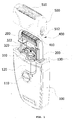
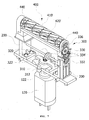
- a cutting blade assembly of a rotation drum type electric razor includes a razor body 100 on which an on/off switch 110 is formed and in which a driving motor 120 operated by the on/off switch 110 is embedded, a driving support 200 that is formed uprightly on the left and right side of the razor body 100 faced each other and on the upper end of which a plurality of connection holes is formed, a power transmission means 300 that is provided between the driving support 200 and is connected to the driving motor 120 to transmit a driving force, a cutting blade assembly 400 that is shaft-connected to the connection hole of the driving support 200 and to which a driving force is transmitted from the power transmission means 300 to be rotated at a high speed, and is provided with cutting blades, and a cover 500 that is hook-connected to the upper surface of the razor body 100 and on which a net 510 covering the cutting blade assembly 400 is formed.
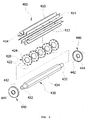
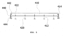
- the cutting blade assembly 400 includes a plurality of cutting blade 410, 412' that is formed extending in a longitudinal direction, on an inner diameter side of which a plurality of first connection groove 412, 412' is formed and on both ends of which second connection groove 414, 414' is formed, a plurality of support piece 420, 420' in a form of a circular plate on which a plurality of cutting blade connection groove 422, 422' to be connected to a plurality of first connection groove 412, 412' of the cutting blade 410, 410', is formed along the outer circumference, and on a center of which a hexagonal hole 424, 424' is formed, a driving shaft 430 on both ends of which a circular shaft part 432 to one side of which the driving support 200 is connected and to the other side of which the power transmission means 300 is connected, is formed, and which includes a hexagonal shaft part 434 that is fitted into the hexagonal hole 424, 424' provided at a center of the support piece 420, 420
- the cutting blade 410 is connected to the cutting blade connection groove 422 to form a cutting angle ⁇ 1, which is formed to have a predetermined inclination angle ⁇ with respect to the support piece 420 support piece, wherein the cutting blade is formed as a horizontal plate type that is connected to the cutting blade connection groove 422 corresponding to the same line downright the first connection groove 412 of the cutting blade 410.
- the cutting blade 410' is connected to the cutting blade connection groove 422' to form a cutting angle ⁇ 3, which is formed to have a predetermined inclination angle ⁇ 2 with respect to the support piece 420, wherein the cutting blade is formed as a spiral plate type that is connected to in order the cutting blade connection groove 422' of the support piece 420' next to one cutting blade connection groove 422' of the support piece 420', corresponding to the same line downright the first connection groove 412' of the cutting blade 410', along the trace of spiral arc.
- a cutting blade assembly of a rotation drum type electric razor includes a razor body 100 and a support 200, a power transmission means 300, a cutting blade assembly 400 and a cover 500.
- a on/off switch 110 is formed on a front surface of the razor body 100 and a driving motor 120 that forms a driving shaft 122 and is operated by a application of power source by the on/off switch 110.
- a cover fastening hole 130 is formed in a form of slim for easy carrying and keeping on the upper surface of the razor body 100 such that the later cover 500 is fastened thereto.
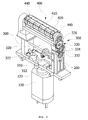
- a fastening hole (not shown) is formed on the upper end of the driving support 200, and the driving supports 200 are formed uprightly faced each other between the cover fastening holes 130 formed on the right and left upper sides of the razor body 100.
- the later power transmission means 300 is provided on at least one side of the driving support 200.
- the power transmission 300 includes a driving motor connection part 310, a power transmission rotation shaft 320 and power transmission gear part 330.
- the driving motor connection part 310 is formed such that the motor shaft 122 of the driving motor 120 is connected to one side of the upper surface of the razor body 100, and a spur gear 312 being rotated together with a rotation of the motor shaft 122 is installed on upper side of the driving motor connection part 310.
- the power transmission rotation shaft 320 is connected rotatably between the driving supports 200 formed uprightly faced each other on the upper surface of the razor body 100.
- one end of the power transmission rotation shaft 320 is connected to at least one gear of the later power transmission gear part 330, and a crown gear 322 that is geared to the spur gear 312 installed on the upper surface of the driving motor connection part 310, is formed on one side of the power transmission rotation shaft 320.
- the crown gear 322 converts a horizontal rotation force from the spur gear 312 of the driving motor connection part 310 into a vertical rotation force to transmit a driving force to the power transmission rotation shaft 320.
- the power transmission gear parts 330 are geared to one surface of at least one driving support 200 formed uprightly faced each other on upper surface of the razor body 100 by a plurality of gears, and shaft-installed.
- the plurality of gear is formed preferably as spur gear, and includes a lower spur gear 332, a middle spur gear 334 and a upper spur gear 336.
- one end of the aforementioned power transmission rotation shaft 320 is connected to the lower spur gear 332 installed on the lower side of the driving support 200 such that a vertical rotation force from the power transmission rotation shaft 320 is transferred to the plural of geared-middle spur gear 334 and further to the upper spur gear 336.
- a rotation force of the upper spur gear 336 that is transmitted from the middle spur gear 334 drives the driving shaft 430, which is connected to the upper spur gear 336, of the later cutting blade assembly 400 that is connected to the upper connection hole (not shown) of the driving support 200, and thus rotates the cutting blade assembly 400.
- the cutting blade assembly 400 includes a cutting blade 410, 410', a support piece 420, 420', a driving shaft 430 and fixing piece 440, as shown in Figs. 3 to 7 or 8 .
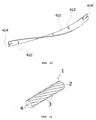
- the cutting blade 410, 410' as shown in Fig. 3 or 5 , is formed as a plate form extending longitudinally, and a plural first connection groove 412, 412' is formed at equal space on one side thereof.
- a second connection groove 414, 414' is formed on both ends of the cutting blade 410, 410', respectively.
- a plurality of the cutting blade 410, 410' is preferably formed on a circumference.
- the cutting blade 410 is formed preferably as a horizontal plate such that the first connection groove 412 that is formed on one side thereof corresponds to in a same line downwardly and is connected to the cutting blade connection groove 422 formed on the outer circumference of the support piece 420.
- the cutting blade 410' may be formed preferably as a spiral plate form curved at a predetermined angle such that a plural of the first connection groove 412' formed on one side thereof are connected to the cutting blade connection groove 422' formed on the outer circumference of the support piece 420' corresponding to the first connection groove 412' in a same line downwardly to be discrepant to the next cutting blade groove 422'.
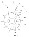
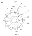
- the support piece 420, 420' is formed as a circular plate, as shown in Fig. 4 or 9 , and a hexagonal hole 424, 424' is formed on a center thereof, and the cutting blade groove 422, 422' is formed at a predetermined angle( ⁇ , ⁇ 2) such that the aforementioned cutting blade 410, 410' is connected thereto to have a cutting angel ( ⁇ 1, ⁇ 3).
- a plurality of the cutting blade connection groove 422, 422' is formed along an outer circumference of the support piece 420, 420' formed as a circular plate, and the number thereof corresponds to the number of the cutting blade 420, 420'.
- the number of the support piece 420, 420' corresponds to the number of the first connection groove 412, 412' of the cutting blade 410, 410' to be connected to the cutting blade groove 422, 422'.
- circular shaft part 432 one side of which is connected to the driving support 200 and the other side of which is connected to the power transmission means 300, is formed on both end of the driving shaft 430, and a hexagonal shaft part 434, which is fitted into the hexagonal hole 424, 424' formed on a center of the support piece 420, 420', is formed between the circular shaft part 432 on the both ends of the driving shaft.
- the fixing piece 440 is formed as a circular form and a connection rib 442 to which the second connection groove 414, 414' formed on both ends of the cutting blade 410, 410' is connected, is formed thereon. Additionally, a through hole 444, through which the circular shaft part 432 formed on both ends of the driving shaft 430 is connected, is formed on a center of the fixing piece 440.
- the fixing piece 440 prevents the cutting blade 410, 410' from being departed from the cutting blade connection groove 422, 422' due to a centrifugal force caused from a high speed rotation.
- a hook piece 512 to be hooked to a cover connection hole 130 of the razor body 100 is formed on the left and right side of the cover 500 and a safety net 510 formed in a space accommodating a rotation diameter of the cutting blade 410, 410' at a high rotation speed, is formed on the upper side of the cover.
- the safety net 510 prevents a human body from being hurt when the cutting blade at a high rotation speed cuts hair, etc.
- the on/off switch 110 formed on the front surface of the razor body 100 is operated to apply power source to the driving motor 120 of the power transmission means 300 to rotate the motor shaft 122 of the driving motor 120.
- the spur gear 312 connected to the motor shaft 122 is rotated at the same time.
- the crown gear 322 of the power transmission rotation shaft 320 that is connected rotatably between the driving support 200 formed uprightly faced each other on the upper surface of the razor body 100, is connected to the upper spur gear 312 of the driving motor connection part 310, which is rotated horizontally, to convert into vertical rotation, and thus it rotates the power transmission rotation shaft 320.
- at least one end of the power transmission rotation shaft 320 among both ends thereof is connected to the lower spur gear 332 of the power transmission gear part 330 to transmit a rotation force, as described above.
- one lower spur gear 332 of the power transmission gear part 330 to which a rotation force is transmitted by the power transmission rotation shaft 320 is rotated vertically as same as the power transmission rotation shaft 320, and the middle spur gear 334 geared to the respective power transmission gear part 330 transmits a rotation force to the uppermost spur gear 336 connected to one side end of the cutting blade 410.
- the driving shaft 430 of a cutting blade assembly 400 connected to the uppermost spur gear 336 of the power transmission gear part 330 is rotated.
- the both ends of the driving shaft 430 are formed as a circular shaft part 432, respectively, and the middle between the both ends is formed as a hexagonal shaft part 434 in a hexagonal shape. Accordingly, the driving shaft 434 is rotated at a high speed by the rotation force transmitted from the driving motor 120.
- a plurality of support piece 420 on a center of which the hexagonal hole 424 is formed is connected to the hexagonal shaft part 434 of the driving shaft 430 being rotated at a high speed by the rotation force transmitted from the driving motor 120.
- a plurality of cutting blade connection groove 422 having a predetermined angle ( ⁇ ) is formed on the outer circumferential surface of the support piece 420 and a plurality of cutting blade 410 in a form of horizontal plate is connected thereto, and thus hair is cut continuously by a plurality of cutting blade 410 to improve cutting ability at high rotation speed.
- a plurality of first connection groove 412 is formed at equal space on the horizontal plate type cutting blade 410 and the second connection groove 414 is formed on both ends thereof. That is, the first connection groove 412 of the horizontal plate type cutting blade 410 and a plurality of the cutting blade connection groove 422 formed on the outer circumference of the support piece 420 at a predetermined angle ( ⁇ ) are connected correspondingly in a same line to form a cutting angle ( ⁇ 1) such that the improved cutting ability can be obtained when the cutting blade assembly 400 at a high rotation speed cuts hair.
- connection groove 414 formed on both ends of the horizontal plate type cutting blade 410 is connected to the connection rib 442 of the fixing piece 440. That is, the horizontal plate type cutting blade 410 is fitted into the support piece 420 connected to the driving shaft 430 to have a cutting angle ( ⁇ 1) such that it can prevent the horizontal plate type cutting blade 410 from being departed from the support piece 420 by a centrifugal force caused from a high speed rotation.
- the on/off switch 110 formed on the front surface of the razor body 100 is operated to be ON for rotating the spiral plate type cutting blade assembly 400 at a high speed to cut hair, wherein the procedures in which the rotation force from the driving motor 120 is transmitted to the spiral plate type cutting blade assembly 400 to be rotated at a high speed, is to be understood through the embodiment 1, and thus detailed description thereof is omitted.
- the spiral plate type cutting blade assembly 400 as shown in Fig. 9 , a plurality of cutting blade groove 422' having a predetermined angle ( ⁇ 2) is formed on the outer circumference of the support piece 420', and a plurality of the spiral plate type cutting blade 410' is connected thereto, and thereby cutting hair continuously by the plurality of the spiral plate type cutting blade 410' to improve a cutting ability at a high rotation speed.
- a plurality of the first connection groove 412' is connected to a spiral arc of the spiral plate type cutting blade 410' at an equal distance, and the second connection groove 414' is formed on the both ends thereof.
- connection groove 414' formed on both ends of the spiral plate type cutting blade 410' is connected to the connection rib 442 of the fixing piece 440 as the same way as the embodiment 1, and the cutting blade 410' is fitted into the support piece 420' connected to the driving shaft 430 to have a cutting angle ( ⁇ 3), and thereby preventing the cutting blade of the spiral plate type being departed from the support piece 420' due to a centrifugal force caused from a high speed rotation.
- a fabricating of a cutting blade assembly of a rotation drum type electric razor is performed easily through a plurality of connection groove, and it is evident that a disassembly thereof is performed easily.
- a cutting angle is formed easily by only fabricating of cutting blades and support pieces to improve a cutting ability and further for hair not to be held between the cutting blades by forming the most optimum cutting angle.
Landscapes
- Life Sciences & Earth Sciences (AREA)
- Forests & Forestry (AREA)
- Engineering & Computer Science (AREA)
- Mechanical Engineering (AREA)
- Dry Shavers And Clippers (AREA)
Claims (3)
- Schneidklingenanordnung eines Drehtrommel-Elektrorasierers, die enthält:einen Rasierer-Hauptkörper (100), an dem ein An-/Aus-Schalter (110) ausgebildet ist undin dem ein Antriebsmotor (120) eingebettet ist, der durch den An-/Aus-Schalter (110) betätigt wird;Antriebsträger (200), die aufrechtstehend an der linken und der rechten Seite einer oberen Fläche des Rasierer-Hauptkörpers (100) einander zugewandt ausgebildet sind und an deren oberem Ende eine Vielzahl von Verbindungslöchern ausgebildet sind;eine Kraftübertragungseinrichtung (300), die zwischen den Antriebsträgern (200) vorhanden und mit dem Antriebsmotor (120) verbunden ist, um eine Antriebskraft zu übertragen;eine Schneidklingenanordnung (400), die in Wellenverbindung mit dem Verbindungsloch des Antriebsträgers (200) steht und auf die eine Antriebskraft von der Kraftübertragungseinrichtung (300) übertragen wird, so dass sie sich mit einer hohen Geschwindigkeit dreht,und die mit Schneidklingen (410) versehen ist; undeine Abdeckung (500), die über Haken mit der oberen Fläche des Rasierer-Hauptkörpers (100) verbunden ist und an der ein Netz (510) ausgebildet ist, das die Schneidklingenanordnung (400) abdeckt,dadurch gekennzeichnet, dass die Schneidklingenanordnung (400) enthält:eine Vielzahl von Schneidklingen (410, 410'), die sich plattenförmig in einer Längsrichtung erstrecken, an deren Innendurchmesserseite eine Vielzahl erster Verbindungsnuten (412, 412') ausgebildet sind und an deren beiden Enden zweite Verbindungsnuten (414, 414') ausgebildet sind;eine Vielzahl von Trageteilen (420, 420') in Form einer kreisförmigen Platte, an der eine Vielzahl von Schneidklingen-Verbindungsnuten (422, 422'), die mit der Vielzahl erster Verbindungsnuten (412, 412') der Schneidklinge (410, 410') zu verbinden sind, am Außenumfang entlang ausgebildet sind, und in deren Mitte ein Sechskantloch (424, 424') ausgebildet ist;eine Antriebswelle (430), an deren beiden Enden ein kreisförmiger Wellenteil (432) ausgebildet ist, mit dessen einer Seite der Antriebsträger (200) verbunden ist und mit dessen anderer Seite die Kraftübertragungseinrichtung (300) verbunden ist, und die einen Sechskant-Wellenteil (434) enthält, der in das Sechskantloch (424, 424') eingepasst ist, das in der Mitte der Trageteile (420, 420') zwischen dem jeweiligen kreisförmigen Wellenteil (432) vorhanden ist; undein Fixierteil (440), an dem eine Verbindungsrippe (442) ausgebildet ist, die mit den zweiten Verbindungsnuten (414, 414') der Schneidklingen (410, 410') zu verbinden ist und an dem ein Durchgangsloch (444) ausgebildet ist, über das der kreisförmige Wellenteil (432) der Antriebswelle (430) verbunden ist.
- Schneidklingenanordnung eines Drehtrommel-Elektrorasierers nach Anspruch 1, wobei die Schneidklinge (410) mit der Schneidklingen-Verbindungsnut (422) verbunden ist, um einen Schneidwinkel (θ1) zu bilden, der so ausgebildet ist, dass er einen vorgegebenen Neigungswinkel (θ) in Bezug auf den Trageteil (420) hat, wobei die Schneidklinge als eine horizontale Platte ausgebildet ist, die mit den Schneidklingen-Verbindungsnuten (422) auf der gleichen Linie unterhalb der ersten Verbindungsnuten (412) der Schneidklinge (410) verbunden ist.
- Schneidklingenanordnung eines Drehtrommel-Elektrorasierers nach Anspruch 1, wobei die Schneidklinge (410) mit der Schneidklingen-Verbindungsnut (422) verbunden ist, um einen Schneidwinkel (θ1) zu bilden, der so ausgebildet ist, dass er einen vorgegebenen Neigungswinkel (θ) in Bezug auf den Trageteil (420) hat, wobei die Schneidklinge als eine spiralförmige Platte ausgebildet ist, die mit der Schneidklingen-Verbindungsnut (422') des Trageteils (420') neben einer Schneidklingen-Verbindungsnut (422') des Trageteils (420') auf der gleichen Linie unterhalb der ersten Verbindungsnut (412') der Schneidklinge (410') entlang der Bahn des Spiralbogens verbunden ist.
Applications Claiming Priority (1)
| Application Number | Priority Date | Filing Date | Title |
|---|---|---|---|
| KR2020060024493U KR200432537Y1 (ko) | 2006-09-12 | 2006-09-12 | 회전 드럼식 전기면도기의 절삭날 어셈블리 |
Publications (2)
| Publication Number | Publication Date |
|---|---|
| EP1900487A1 EP1900487A1 (de) | 2008-03-19 |
| EP1900487B1 true EP1900487B1 (de) | 2011-03-02 |
Family
ID=38792459
Family Applications (1)
| Application Number | Title | Priority Date | Filing Date |
|---|---|---|---|
| EP07107711A Not-in-force EP1900487B1 (de) | 2006-09-12 | 2007-05-08 | Schneideklingenanordnung eines elektrischen Rasierers mit Drehtrommel |
Country Status (4)
| Country | Link |
|---|---|
| US (1) | US20080060202A1 (de) |
| EP (1) | EP1900487B1 (de) |
| KR (1) | KR200432537Y1 (de) |
| DE (1) | DE602007012806D1 (de) |
Families Citing this family (14)
| Publication number | Priority date | Publication date | Assignee | Title |
|---|---|---|---|---|
| US20070220755A1 (en) * | 2004-05-11 | 2007-09-27 | Gideon Dror | Shaving Apparatus |
| CN102300684A (zh) * | 2008-11-13 | 2011-12-28 | 紧贴剪剃刀具有限公司 | 剃刀刀头 |
| KR200462957Y1 (ko) * | 2009-05-28 | 2012-10-11 | 오태준 | 회전드럼식 전기면도기의 끼움식 절삭날 어셈블리 |
| US10456935B2 (en) | 2010-01-18 | 2019-10-29 | Hybrid Razor Ltd | Shaving apparatus and shaving apparatus head |
| JP5550157B2 (ja) * | 2010-01-18 | 2014-07-16 | ハイブリツド・レイザー・リミテツド | モーターの付いたシェービング装置ヘッドと、同様な構造を備えるシェービング装置 |
| US8601696B2 (en) * | 2010-01-18 | 2013-12-10 | Hybrid Razor Ltd | Motorized shaving apparatus head and shaving apparatus implementing the same |
| WO2011119196A1 (en) * | 2010-03-20 | 2011-09-29 | Haitham Yousef Serhan | Apparatus for stimulating fresh skin |
| US8887401B2 (en) * | 2012-06-18 | 2014-11-18 | Anthony J. Oxford | Rotating blade assembly |
| EP2996844A2 (de) * | 2013-05-17 | 2016-03-23 | Hybrid Razor Ltd | Rasierapparat |
| WO2015125021A2 (en) * | 2014-02-18 | 2015-08-27 | Hybrid Razor Ltd. | Shaving apparatus |
| KR101691924B1 (ko) * | 2015-03-04 | 2017-01-17 | 박보현 | 회전드럼식 전기면도기의 절삭날 어셈블리 |
| US10391650B2 (en) * | 2015-11-03 | 2019-08-27 | Spectrum Brands, Inc. | Hair grooming appliance |
| EP3524396B1 (de) * | 2018-02-08 | 2020-12-02 | BIC Violex S.A. | Rotationsrasierapparat |
| SE544810C2 (en) | 2020-12-18 | 2022-11-29 | Mektig Tech Group Ab | Electric shaver with a rotating drum |
Family Cites Families (8)
| Publication number | Priority date | Publication date | Assignee | Title |
|---|---|---|---|---|
| US2321932A (en) * | 1938-07-21 | 1943-06-15 | Barney R Nyhagen | Hair cutting implement |
| FR1050751A (fr) * | 1952-01-02 | 1954-01-11 | Perfectionnements aux rasoirs mécaniques | |
| NL8503521A (nl) * | 1985-12-20 | 1987-07-16 | Philips Nv | Scheerapparaat. |
| US4985999A (en) * | 1988-10-15 | 1991-01-22 | Matsushita Electric Works, Ltd. | Hand-held clipper for removing entangled fibers from the surface of fabrics |
| US5014428A (en) * | 1989-03-06 | 1991-05-14 | Kyushu Hitachi Maxell, Ltd. | Rotary type electric razor |
| GB2230489A (en) * | 1989-04-12 | 1990-10-24 | Carl Mfg Co | Cutter for shredder |
| US5197196A (en) * | 1990-09-22 | 1993-03-30 | Kyushu Hitachi Maxell, Ltd. | Spiral cutter for use in an electric razor and a method for manufacturing the cutter |
| KR200361435Y1 (ko) * | 2004-06-01 | 2004-09-14 | 오태준 | 회전드럼식 전기면도기의 절삭날 어셈블리 |
-
2006
- 2006-09-12 KR KR2020060024493U patent/KR200432537Y1/ko not_active Expired - Fee Related
-
2007
- 2007-05-08 DE DE602007012806T patent/DE602007012806D1/de active Active
- 2007-05-08 EP EP07107711A patent/EP1900487B1/de not_active Not-in-force
- 2007-05-15 US US11/748,813 patent/US20080060202A1/en not_active Abandoned
Also Published As
| Publication number | Publication date |
|---|---|
| EP1900487A1 (de) | 2008-03-19 |
| KR200432537Y1 (ko) | 2006-12-05 |
| US20080060202A1 (en) | 2008-03-13 |
| DE602007012806D1 (de) | 2011-04-14 |
Similar Documents
| Publication | Publication Date | Title |
|---|---|---|
| EP1900487B1 (de) | Schneideklingenanordnung eines elektrischen Rasierers mit Drehtrommel | |
| SU1687024A3 (ru) | Ножева головка куттера | |
| EP2213427A1 (de) | Klingeneinheit für elektrischen Rasierapparat | |
| US20170144317A1 (en) | Rotary electric shaver and method of manufacturing inner blade of rotary electric shaver | |
| WO2005099415A3 (en) | Rotary wing vehicle | |
| CN102907209A (zh) | 割灌机 | |
| JP2008253216A (ja) | 刈払機用ロータリーカッタ | |
| JP6339417B2 (ja) | ロータリー式電気かみそり | |
| US8316546B2 (en) | Insert type blade assembly of rotation drum type electric razor | |
| JP6472761B2 (ja) | ローターおよびマルチコプター | |
| CN109414827A (zh) | 用于个人护理器具的刀头 | |
| WO2005107373A3 (en) | Shaving apparatus | |
| CN207496271U (zh) | 防水票据打印机 | |
| EP1413406B1 (de) | Elektrischer Rasierer | |
| KR101281907B1 (ko) | 선풍기의 좌, 우 선회각 조절장치 | |
| WO2007129171A3 (en) | Multiblade safety razor | |
| US3106775A (en) | Interchangeable revolving electric shaver head | |
| EP1793701B1 (de) | Vorrichtung zur aufnahme von austauschbaren körperpflegeeinheiten | |
| KR101691924B1 (ko) | 회전드럼식 전기면도기의 절삭날 어셈블리 | |
| US20210114241A1 (en) | External cutting member of a shaving device having hair-guiding elements with thickness profile | |
| US7065878B2 (en) | Rotary type electric shaver | |
| KR200232085Y1 (ko) | 전기면도기 | |
| WO2005118235A1 (en) | Cutting blade assembly of rotary drum type electric razor | |
| ES2483144T3 (es) | Herramienta y aparato de cocina, en particular mezcladora de barra | |
| CN206565844U (zh) | 食物处理器 |
Legal Events
| Date | Code | Title | Description |
|---|---|---|---|
| PUAI | Public reference made under article 153(3) epc to a published international application that has entered the european phase |
Free format text: ORIGINAL CODE: 0009012 |
|
| AK | Designated contracting states |
Kind code of ref document: A1 Designated state(s): AT BE BG CH CY CZ DE DK EE ES FI FR GB GR HU IE IS IT LI LT LU LV MC MT NL PL PT RO SE SI SK TR |
|
| AX | Request for extension of the european patent |
Extension state: AL BA HR MK YU |
|
| 17P | Request for examination filed |
Effective date: 20080910 |
|
| 17Q | First examination report despatched |
Effective date: 20081024 |
|
| AKX | Designation fees paid |
Designated state(s): DE FR GB |
|
| GRAP | Despatch of communication of intention to grant a patent |
Free format text: ORIGINAL CODE: EPIDOSNIGR1 |
|
| GRAS | Grant fee paid |
Free format text: ORIGINAL CODE: EPIDOSNIGR3 |
|
| GRAA | (expected) grant |
Free format text: ORIGINAL CODE: 0009210 |
|
| AK | Designated contracting states |
Kind code of ref document: B1 Designated state(s): DE FR GB |
|
| REG | Reference to a national code |
Ref country code: GB Ref legal event code: FG4D |
|
| REF | Corresponds to: |
Ref document number: 602007012806 Country of ref document: DE Date of ref document: 20110414 Kind code of ref document: P |
|
| REG | Reference to a national code |
Ref country code: DE Ref legal event code: R096 Ref document number: 602007012806 Country of ref document: DE Effective date: 20110414 |
|
| PLBE | No opposition filed within time limit |
Free format text: ORIGINAL CODE: 0009261 |
|
| STAA | Information on the status of an ep patent application or granted ep patent |
Free format text: STATUS: NO OPPOSITION FILED WITHIN TIME LIMIT |
|
| 26N | No opposition filed |
Effective date: 20111205 |
|
| REG | Reference to a national code |
Ref country code: DE Ref legal event code: R097 Ref document number: 602007012806 Country of ref document: DE Effective date: 20111205 |
|
| PGFP | Annual fee paid to national office [announced via postgrant information from national office to epo] |
Ref country code: GB Payment date: 20140530 Year of fee payment: 8 |
|
| PGFP | Annual fee paid to national office [announced via postgrant information from national office to epo] |
Ref country code: DE Payment date: 20140530 Year of fee payment: 8 |
|
| PGFP | Annual fee paid to national office [announced via postgrant information from national office to epo] |
Ref country code: FR Payment date: 20140530 Year of fee payment: 8 |
|
| REG | Reference to a national code |
Ref country code: DE Ref legal event code: R119 Ref document number: 602007012806 Country of ref document: DE |
|
| GBPC | Gb: european patent ceased through non-payment of renewal fee |
Effective date: 20150508 |
|
| REG | Reference to a national code |
Ref country code: FR Ref legal event code: ST Effective date: 20160129 |
|
| PG25 | Lapsed in a contracting state [announced via postgrant information from national office to epo] |
Ref country code: GB Free format text: LAPSE BECAUSE OF NON-PAYMENT OF DUE FEES Effective date: 20150508 Ref country code: DE Free format text: LAPSE BECAUSE OF NON-PAYMENT OF DUE FEES Effective date: 20151201 |
|
| PG25 | Lapsed in a contracting state [announced via postgrant information from national office to epo] |
Ref country code: FR Free format text: LAPSE BECAUSE OF NON-PAYMENT OF DUE FEES Effective date: 20150601 |