EP1900441A1 - Slide curtain coating apparatus and slide curtain coating method - Google Patents
Slide curtain coating apparatus and slide curtain coating method Download PDFInfo
- Publication number
- EP1900441A1 EP1900441A1 EP07116480A EP07116480A EP1900441A1 EP 1900441 A1 EP1900441 A1 EP 1900441A1 EP 07116480 A EP07116480 A EP 07116480A EP 07116480 A EP07116480 A EP 07116480A EP 1900441 A1 EP1900441 A1 EP 1900441A1
- Authority
- EP
- European Patent Office
- Prior art keywords
- slide
- curtain
- auxiliary liquid
- edge guide
- coating
- Prior art date
- Legal status (The legal status is an assumption and is not a legal conclusion. Google has not performed a legal analysis and makes no representation as to the accuracy of the status listed.)
- Granted
Links
- 238000007766 curtain coating Methods 0.000 title claims abstract description 102
- 238000000034 method Methods 0.000 title claims abstract description 36
- 239000007788 liquid Substances 0.000 claims abstract description 244
- 238000000576 coating method Methods 0.000 claims abstract description 137
- 239000011248 coating agent Substances 0.000 claims abstract description 134
- 238000007599 discharging Methods 0.000 claims abstract description 13
- 238000011084 recovery Methods 0.000 claims description 30
- 239000011148 porous material Substances 0.000 claims description 25
- 230000003068 static effect Effects 0.000 claims description 12
- 230000008021 deposition Effects 0.000 claims description 2
- 238000000151 deposition Methods 0.000 abstract description 2
- XLYOFNOQVPJJNP-UHFFFAOYSA-N water Substances O XLYOFNOQVPJJNP-UHFFFAOYSA-N 0.000 description 8
- 239000000919 ceramic Substances 0.000 description 7
- 230000000052 comparative effect Effects 0.000 description 4
- 238000001035 drying Methods 0.000 description 4
- 238000002156 mixing Methods 0.000 description 4
- 239000002904 solvent Substances 0.000 description 4
- 239000004094 surface-active agent Substances 0.000 description 4
- 229920006362 Teflon® Polymers 0.000 description 3
- 230000006872 improvement Effects 0.000 description 3
- XAGFODPZIPBFFR-UHFFFAOYSA-N aluminium Chemical compound [Al] XAGFODPZIPBFFR-UHFFFAOYSA-N 0.000 description 2
- 229910052782 aluminium Inorganic materials 0.000 description 2
- 239000004615 ingredient Substances 0.000 description 2
- 239000000463 material Substances 0.000 description 2
- 238000002360 preparation method Methods 0.000 description 2
- 239000011347 resin Substances 0.000 description 2
- 229920005989 resin Polymers 0.000 description 2
- 229910001220 stainless steel Inorganic materials 0.000 description 2
- 239000010935 stainless steel Substances 0.000 description 2
- 239000004372 Polyvinyl alcohol Substances 0.000 description 1
- 230000015572 biosynthetic process Effects 0.000 description 1
- 230000000903 blocking effect Effects 0.000 description 1
- 239000003086 colorant Substances 0.000 description 1
- 230000002950 deficient Effects 0.000 description 1
- 238000011156 evaluation Methods 0.000 description 1
- 230000005484 gravity Effects 0.000 description 1
- 239000001056 green pigment Substances 0.000 description 1
- 238000004519 manufacturing process Methods 0.000 description 1
- 238000005259 measurement Methods 0.000 description 1
- 230000007246 mechanism Effects 0.000 description 1
- 229920002451 polyvinyl alcohol Polymers 0.000 description 1
- 230000008569 process Effects 0.000 description 1
- 230000009467 reduction Effects 0.000 description 1
- 238000007767 slide coating Methods 0.000 description 1
- 230000008719 thickening Effects 0.000 description 1
- 238000011144 upstream manufacturing Methods 0.000 description 1
Images



Classifications
-
- B—PERFORMING OPERATIONS; TRANSPORTING
- B05—SPRAYING OR ATOMISING IN GENERAL; APPLYING FLUENT MATERIALS TO SURFACES, IN GENERAL
- B05C—APPARATUS FOR APPLYING FLUENT MATERIALS TO SURFACES, IN GENERAL
- B05C5/00—Apparatus in which liquid or other fluent material is projected, poured or allowed to flow on to the surface of the work
- B05C5/007—Slide-hopper coaters, i.e. apparatus in which the liquid or other fluent material flows freely on an inclined surface before contacting the work
- B05C5/008—Slide-hopper curtain coaters
-
- G—PHYSICS
- G03—PHOTOGRAPHY; CINEMATOGRAPHY; ANALOGOUS TECHNIQUES USING WAVES OTHER THAN OPTICAL WAVES; ELECTROGRAPHY; HOLOGRAPHY
- G03C—PHOTOSENSITIVE MATERIALS FOR PHOTOGRAPHIC PURPOSES; PHOTOGRAPHIC PROCESSES, e.g. CINE, X-RAY, COLOUR, STEREO-PHOTOGRAPHIC PROCESSES; AUXILIARY PROCESSES IN PHOTOGRAPHY
- G03C1/00—Photosensitive materials
- G03C1/74—Applying photosensitive compositions to the base; Drying processes therefor
-
- B—PERFORMING OPERATIONS; TRANSPORTING
- B05—SPRAYING OR ATOMISING IN GENERAL; APPLYING FLUENT MATERIALS TO SURFACES, IN GENERAL
- B05C—APPARATUS FOR APPLYING FLUENT MATERIALS TO SURFACES, IN GENERAL
- B05C9/00—Apparatus or plant for applying liquid or other fluent material to surfaces by means not covered by any preceding group, or in which the means of applying the liquid or other fluent material is not important
- B05C9/06—Apparatus or plant for applying liquid or other fluent material to surfaces by means not covered by any preceding group, or in which the means of applying the liquid or other fluent material is not important for applying two different liquids or other fluent materials, or the same liquid or other fluent material twice, to the same side of the work
-
- Y—GENERAL TAGGING OF NEW TECHNOLOGICAL DEVELOPMENTS; GENERAL TAGGING OF CROSS-SECTIONAL TECHNOLOGIES SPANNING OVER SEVERAL SECTIONS OF THE IPC; TECHNICAL SUBJECTS COVERED BY FORMER USPC CROSS-REFERENCE ART COLLECTIONS [XRACs] AND DIGESTS
- Y10—TECHNICAL SUBJECTS COVERED BY FORMER USPC
- Y10S—TECHNICAL SUBJECTS COVERED BY FORMER USPC CROSS-REFERENCE ART COLLECTIONS [XRACs] AND DIGESTS
- Y10S118/00—Coating apparatus
- Y10S118/04—Curtain coater
Definitions
- the present invention relates to a slide curtain coating apparatus and slide curtain coating method for applying coating liquid on a running web..
- Curtain coating apparatuses are commonly used in manufacturing processes of photosensitive materials such as photographic films.
- FIG. 1 shows an example of a conventional curtain coating apparatus
- the curtain coating apparatus 4 (or curtain coating head) includes one or more slits S as means for discharging a coating liquid 6.
- slits S By discharging coating liquids 6 on the surface of a slide 1 from the multiple slits S, layers or curtain of the coating liquids 6 are formed on the surface of the slide 1.
- the laminate of the coating liquids 6, or curtain then freely falls from the inclined surface of the slide 1 and contacts a web 5 running on a conveyor (not shown), forming a coating on the web 5.
- the curtain coating apparatus 4 further includes at least a pair of slide edge guides 2 and a pair of curtain edge guides 3.
- the present invention relates to an improvement of such a curtain coating apparatus.
- the curtain coating method according to the present invention is directed to a method of forming a multilayer coating which involves the use of the aforementioned curtain coating apparatus, wherein coating liquids with different functions are discharged from different slits such that the coating liquids are stacked on top of each other on the slide surface to form a curtain, which then falls freely down on the running web to form a coating thereon.
- the drying temperature may be raised in the drying process; however, high drying temperatures are not desirable for the formation of, for example, thermosensitive paper which develops colors upon exposure to high temperatures, leading to such problems as defective products. For this reason, this approach cannot be used for curtain coating in many cases.
- JP-A Japanese Patent Application Laid-Open ( JP-A) Nos. 2000-513 , 2000-218209 , 2001-104856 and 2005-512768 propose techniques for preventing the edge regions from becoming thicker
- an auxiliary liquid is allowed to flow essentially parallel to the flow direction of the curtain along edge guides of the slide, so that the flow rates at the opposing edges of the slide are made close to the flow rate at the center.
- the proposed techniques are disadvantageous in that, since a large amount of the auxiliary liquid needs to be supplied along the edges of the slide, the auxiliary liquid may be easily mixed with the curtain. And further, these technique have met with difficulties in stably and uniformly supplying the auxiliary liquid along the edge regions, resulting in non-uniform in thickness along its width.
- An additional disadvantage is that a complicated coating apparatus is required for this.
- the present invention is to solve the aforementioned problems and to achieve the following object. That is, the present invention is to provide a slide curtain coating apparatus and slide curtain coating method wherein coating liquids are applied in the form of a curtain on a running web to form a coating on the surface thereof, the apparatus and method being capable of preventing the curtain from converging to the center of the slide and of preventing the resultant coating from having greater thickness at its edge regions.
- the slide curtain coating apparatus of the present invention includes: a slit configured to discharge a coating liquid; a slide having an inclined surface on which the coating liquid flows down in the form of curtain; a slide edge guide provided at each of both edges of the slide; and auxiliary liquid supply means configured to discharge an auxiliary liquid from all over the surface thereof which touches the curtain at the edge guide.
- the curtain freely falls from the slide and contacts a running web to form a coating thereon.
- the auxiliary liquid supply means discharges an auxiliary liquid from all over the surface thereof which touches the curtain at the slide edge guide, it is possible to prevent deposition of a large amount of coating liquid onto edge regions of the web (i.e., to prevent the resulting coating on the web from having a greater thickness at its edge regions). In this way the coating can be prevented from adhering to any other surface of the web, and the web can be prevented from being torn up when it is rolled, thereby increasing the efficiency of curtain coating..
- the auxiliary liquid supply means enable to reduce the required amount of the auxiliary liquid to be discharged, and thus the curtain can be almost completely prevented from being mixed with the auxiliary liquid. Thereby the coating can be prevented from having, or being mixed with, the auxiliary liquid at the edge regions.
- each edge guide that makes contact with the auxiliary liquid is preferably made of porous material.
- the porous material preferably has an average pore size of 50 ⁇ m or smaller.
- the porous material preferably has a porosity of 30% or higher.
- the auxiliary liquid supply means enables to uniformly supply the auxiliary liquid on the slide, stabilize and equalize the flow rate of the curtain, prevent the coating thickness at edge regions from being thicker than the center region, and thereby the coating can be prevented from adhering to any other surface of the web, and the web can be prevented from being torn up when it is rolled, increasing the efficiency of curtain coating.
- the height of the auxiliary liquid supply means is preferably equal to the thickness, or depth, of the flowing curtain.
- the height of the auxiliary liquid supply means is preferably made equal to the thickness of the curtain, and also, a thickness regulator is preferably provided on the auxiliary liquid supply means in such a manner that the contact angle between the thickness regulator and the auxiliary liquid is 90° or wider,
- the height of flowing auxiliary liquid being discharged from and adjacent to the auxiliary liquid supply means is preferably controlled at the level equal to the thickness of the curtain, In such a configuration, the curtain of coating liquid can be prevented from being mixed with the auxiliary liquid, and thereby the edge regions of the resulting coating can be prevented from mixed with the auxiliary liquid.
- a plurality of coating liquids is discharged from the corresponding number of slits, and flows down the inclined surface of a slide while being laminated as a curtain, and the curtain falls freely from the slide and contacts a running web, forming a coating thereon, wherein the method is characterized in that an auxiliary liquid is supplied from auxiliary liquid supply means at a pair of slide edge guides provided at opposing edges on the slide, the auxiliary liquid supply means discharges the auxiliary liquid from all over the surface thereof which touches the curtain.
- the height of flowing auxiliary liquid discharged from the auxiliary liquid supply means is preferably equal to the thickness of the curtain.
- a slide curtain coating method it is possible to prevent the edge regions of the coating from having greater a thickness than its center region, preventing the coating from adhering to any other surface of the web.
- the web is prevented from being torn up when it is rolled, increasing the efficiency of curtain coating.
- the auxiliary liquid supply means expanding all over the surface of each slide edge guide that touches the curtain achieves a reduction in the amount of auxiliary liquid needed to be discharged, and thus the curtain can be almost completely prevented from being mixed with the auxiliary liquid. Thereby the coating can be prevented from being mixed with the auxiliary liquid.
- the slide curtain coating apparatus preferably includes a recovery blade at the downstream of each slide edge guide as means for collecting the auxiliary liquid that has been discharged from the auxiliary liquid supply means.
- the slide curtain coating apparatus of the present invention it is preferable to provide recovery means at each edge for collecting the flowing auxiliary liquid at the downstream of the slide edge guide by means of recovery blade, while moving the position of each slide edge guide facing the auxiliary liquid and curtain from the edge of the flow of the curtain by a distance corresponding to the flow width of the auxiliary liquid.
- the length of the blade is preferably equal to the flow width of the auxiliary liquid flowing between the auxiliary liquid supply means and the edge of the flowing curtain.
- suction means is preferably provided for suctioning a Rowing auxiliary liquid, which has been discharged from the auxiliary supply means, through a path formed at the downstream of each slide edge guide.
- the curtain coating apparatus With the curtain coating apparatus with such suction means, it is possible to prevent the curtain from being mixed with the auxiliary liquid and the coating from having greater thickness at its edge legions, thereby the coating can be prevented from adhering to any other surface of the web, and the web will not be easily torn up when it is rolled, increasing the efficiency of curtain coating.
- suction means at each edge to collect flowing auxiliary liquid at the downstream of each slide edge guide, while moving the position of' each of the slide edge guide facing the auxiliary liquid and curtain from the edge of the flow of the curtain by a distance corresponding to the flow width of the auxiliary liquid.
- the curtain coating apparatus having the suction means provided in such a manner, it is possible to prevent the curtain from being mixed with the auxiliary liquid and the coating from having greater thickness at their edge regions, thereby the coating can be prevented from adhering to the other surface of the web, and the web will not be easily torn up when the web is rolled, increasing the efficiency of curtain coating.
- the curtain coating apparatus with the recovery blade preferably contains a suction means at the downstream of the slide edge guides for suctioning the auxiliary liquid collected by means of the recovery blade.
- coating liquids are discharged through respective slits, flow as a curtain down the inclined surface of the slide, and freely fall from the slide and contact the running web, forming the coating thereon, wherein the method is characterized in that the auxiliary liquid is provided from the auxiliary liquid supply means at the slide edge guides provided at opposing edges of the slide, the auxiliary liquid supply means discharges the auxiliary liquid from all over the surface thereof which touches the curtain, and the Bowing auxiliary liquid is then suctioned with the suction means through the path formed at the end of the slide edge guides at the downstream.
- the curtain coating method of the present invention coating liquids are discharged through respective slits, flow as a curtain down the inclined surface of the slide, and freely fall from the slide and contact the running web, forming the coating thereon, wherein the method is characterized in that the slide curtain coating apparatus of the present invention which has the suction means is used to discharge the auxiliary liquid from all over a surface which touches the curtain at a slide edge guide, and to suction the auxiliary liquid at the downstream of the slide edge guide, with the position of the slide edge guide being moved in the direction opposite to the discharge direction of the auxiliary liquid from the slide edge guide by a distance corresponding to the flow width of the auxiliary liquid.
- the slide curtain coating method of the present invention is further characterized in that the flowing auxiliary liquid is collected using the above-stated curtain coating apparatus provided with the recovery blade at the downstream of each slide edge guide.
- the slide curtain coating method of the present invention is further characterized in that the flowing auxiliary liquid is collected at the downstream of the slide edge guide by means of recovery blade, while moving the position of each slide edge guide facing the auxiliary liquid and curtain from the edge of the flow of the curtain by a distance corresponding to the flow width of the auxiliary liquid.
- the auxiliary liquid collected through the recovery blades be suctioned with the suction means through the path formed at the end of the slide edge guides at the downstream.
- the height of the auxiliary liquid being discharged from the auxiliary liquid supply means is preferably equal to the thickness of the curtain.
- the slide curtain coating method of the present invention it is possible to prevent the edge regions of the resulting coating from having greater thickness than its center legion, preventing the coating from adhering to any other surface of the web.
- the web is prevented from being torn up when it is rolled, increasing the efficiency of curtain coating.
- the auxiliary liquid supply means expanded to the entire contact area at the surface of the slide edge guides enable to reduce the required amount of the auxiliary liquid to be discharged, and thus the auxiliary liquid can be almost completely prevented from being mixed with the curtain.
- the coating can be prevented from having non-uniform thickness in a direction lateral to web motion, the non-uniformity being caused when the curtain is mixed with the auxiliary liquid.
- each of the slide edge guides by moving the position of each of the slide edge guides from the edge of the flow of the curtain by a distance corresponding to of the flow width of the auxiliary liquid, by providing a recovery blade for collecting a flowing auxiliary liquid, or by adopting these means in combination, it is possible to further effectively achieve improvements corresponding to the selected means.. It is also desirable that the height of flowing auxiliary liquid be controlled at a level equal to the height of the curtain for more improvement.
- the static surface tension of the auxiliary liquid be in the range of from 10 mN/m lower to 30 mN/m higher than that of the coating liquid.
- FIG. 1 shows an example of a conventional curtain coating apparatus.
- FIG. 2 shows an embodiment of the slide curtain coating apparatus of the present invention.
- FIG. 3 is a cross-sectional view showing an example of the slide edge guide of the slide curtain coating apparatus of FIG. 2.
- FIG. 4 is a cross-sectional view showing another example of the slide edge guide of the slide curtain coating apparatus of FIG. 2.
- FIG. 5 is a cross-sectional view showing an example of the slide edge guide of the slide curtain coating apparatus in accordance with the third aspect of the present invention.
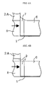
- FIG. 6A is a cross-sectional view showing a fast example of the slide edge guide of the slide curtain coating apparatus in accordance with third embodiment of the present invention..
- FIG. 6B is a cross-sectional view showing a second example of the slide edge guide of the slide curtain coating apparatus in accordance with third embodiment of the present invention.
- FIG. 7 is a cross-sectional view showing an example of the slide edge guide of the slide curtain coating apparatus in accordance with fourth embodiment of the present invention.
- FIG. 8 is a cross-sectional view showing an example of the slide edge guide of the slide curtain coating apparatus in accordance with fifth embodiment of the present invention.
- FIG. 9 is a cross-sectional view showing an example of the slide edge guide of the slide curtain coating apparatus in accordance with sixth embodiment of the present invention.
- FIG. 10 is a cross-sectional view showing an example of the slide edge guide of the slide curtain coating apparatus in accordance with seventh embodiment of the present invention.
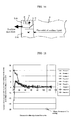
- FIG. 11 shows a graph of variation in the coating thickness vs. distance from the edge of the coatings obtained in Examples and Comparative Examples.
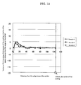
- FIG. 12 shows a graph of variation in the coating thickness vs. distance from the edge of the coatings obtained in Examples.
- FIG. 2 shows a slide curtain coating apparatus in accordance with first embodiment of the invention.
- the slide curtain coating apparatus 4 shown in FIG. 2 includes a plurality of slits S as means for discharging the corresponding number of coating liquids to form a curtain 6 which is composed of layers of the coating liquids; a slide 1 on whose inclined surface the curtain 6 naturally flows; a pair of slide edge guides 2A which are provided on opposing edges of the slide 1 and along which the curtain 6 flows; and, a pair of curtain edge guides 3A at opposing edges at the downstream of'the slide.
- the slide curtain coating apparatus 4 further includes an auxiliary liquid supply mechanism for discharging the auxiliary liquid 7 from the entire surface of the inner surface 2c of each of the slide edge guides 2A, which inner surface 2c is in contact with the curtain 6.
- a web 5 runs on a conveyor (not shown) beneath the slide curtain coating apparatus 4.
- FIG. 3 is a cross-sectional view showing one of the slide edge guides of the slide curtain coating apparatus of FIG. 2.
- the other slide edge guide is not shown as it is identical.
- an auxiliary liquid supplying path 2a through which the auxiliary liquid 7 passes is formed inside the slide edge guide 2A (hereinafter may be simply referred to as "edge guide 2A")
- a wall member 8 that contacts the curtain 6 may be made of porous material or may be provided with very small slits therein such that the auxiliary liquid 7 in the auxiliary liquid supplying path 2a can pass through it..
- the wall member 8 is so configured that the auxiliary liquid 7 in the auxiliary liquid supplying path 2a exudes to, and is constantly held on the surface of the wall member 8 (i.e., the inner surface of the edge guide 2A that contacts the curtain 6) in an appropriate amount.
- the auxiliary liquid 7 is fed from a supply section (not shown).
- the coating liquids 6 discharged through the slits S on the inclined surface of the slide 1 are laminated in the form of curtain 6, and move down the slide 1 by the force of gravity. At this point, the curtain 6 contacts the auxiliary liquid 7 at its ends, whereby the generation of converged flows as seen in the prior art is prevented and thus thickening of the edges of the curtain 6 can be prevented. The curtain 6 then falls from the slide 1 and contacts the running web 5, forming a coating thereon.
- the auxiliary liquid 7 is discharged from the entire surface 2c of each of the opposing edge guides 2A on the slide 1, which surface 2c is in contact with the curtain 6
- the flow rates of portions of the curtain 6 near the edges of the slide 1 increase, and thereby the difference in flow rate between the center and edges of the curtain 6 becomes small, preventing edge flows from converging to the center and preventing the resulting coating from having greater thickness at its edge regions.
- the slide curtain coating apparatus 4 can reduce the amount of the auxiliary liquid 7 needed to be discharged and thus prevent the curtain 6 and the resulting coating from being mixed with the auxiliary liquid 7 at their edge regions by discharging an adequate amount of auxiliary liquid 7 from the entire contact area 2c.
- the auxiliary liquid 7 is not particularly limited as long as it is liquid, i.e., has fluidity.
- aqueous liquids among which preferred are water and aqueous preparations obtained by mixing water with resin, surfactant or the liker and solvent-based liquids, among which preferred are solvents suitably contained in the curtain 6 and solvent preparations obtained by mixing the solvents with resin, surfactant or the like.
- the static surface tension of the auxiliary liquid 7 be in the range of from 10 mN/m lower to 30 mN/m higher and further preferably in the range of from 5 mN/m lower to 20 mN/m higher than that of the coating liquids.
- the static surface tension of the auxiliary liquid 7 is 10 mN/m lower than that of the coating liquids, the auxiliary liquid 7 may be drawn toward the curtain 6 flowing down the slide 1, causing the resulting coating to be mixed with a significant amount of the coating liquids at the edge regions.
- the curtain 6 may be drawn toward the auxiliary liquid 7 while flowing down the slide 1 and thus the coating liquid may be reduced at the edge regions, resulting in significantly insufficient amount of the coating thickness at the edge legions of the resulting coating.
- the slide curtain coating method of the present invention may be performed with the above-stated slide curtain coating apparatus 4 which basically discharges the auxiliary liquid 7 from the contact area 2c at the slide edge guides 2A provided at both edges of the slide 1 to supply a small amount of the auxiliary liquid 7 at the edge regions of the curtain 6.
- the flow rates at the edge regions of the curtain 6 are increased to minimize the difference in flow rate between the center region and the edge regions of the curtain 6, preventing the flow of the curtain 6 from being converged to the center, and preventing the resulting coating from having greater thickness at its edge regions.
- the wall member 8 shown in FIG. 4 is preferably made of porous material in the slide curtain coating apparatus 4 with the above-stated configuration.
- the wall member 8 serves as a porous material member 8, it is possible to minimize the flow depth of the auxiliary liquid 7 and the flow unevenness of the auxiliary liquid 7. Thus, it is possible to prevent thickness unevenness of the edge regions of the coating formed on the web 5.
- the porous material include ceramic, TEFLON®, stainless steel and aluminum.
- the height of the porous material member 8 is adjusted at a level equal to the thickness of the curtain 6 as shown in FIG. 4, it is possible to effectively prevent the curtain 6 from being mixed with the auxiliary liquid 7 at the edge regions.
- the porous material 8 has an average pore size of 50 ⁇ m or smaller and a porosity of 30% or higher, it is possible to stabilize and equalize the flow rate of the auxiliary liquid 7 as well as the curtain 6, in the lateral direction, and thus the flow of the curtain 6 can be prevented from being condensed at its center.
- the thickness regulator 9 can lower the height of the curtain 6 at its edge regions and thus can make the height of the edge regions of the curtain 6 equal to the height of the center region. It is thus possible to prevent the edge regions of the curtain 6 from having greater thickness.
- FIGS. 6B and 6A The comparison between with and without the thickness regulator 9 is shown in FIGS. 6B and 6A.
- Preferred examples of materials that can be used for the thickness regulator 9 include ceramic, TEFLON®, stainless steel and aluminum.
- a suction means is preferably provided in fourth embodiment
- suitably-selected suction means (not shown) is provided at each slide edge guide 2A for suctioning at the downstream of the slide edge guide 1 the auxiliary liquid 7 that has been discharged from the surfaces of the opposing edge guides 2A that contact the curtain 6.
- the curtain 6 is prevented from being mixed with the auxiliary liquid 7, and it is thus possible to prevent mixing of the curtain 6 and auxiliary liquid 7 and to prevent the edge regions of the curtain 6 from having greater thickness.
- the position of the slide edge guide 2A facing the auxiliary liquid 7 and curtain 6 is moved in the direction opposite to the discharge direction of the auxiliary liquid 7 from the edge guide 2A by a distance corresponding to the flow width of the auxiliary liquid 7, wherein a suction means is provided in accordance with the above-stated configuration to suction at the downstream of the slide edge guides 2A the auxiliary liquid 7.
- a suction means is provided in accordance with the above-stated configuration to suction at the downstream of the slide edge guides 2A the auxiliary liquid 7.
- the curtain 6 can be prevented from being mixed with the auxiliary liquid 7, and thereby the edge regions of'the resulting coating on the web can be more effectively prevented from being mixed with the auxiliary liquid 7 and from having greater thickness at its edge regions.
- the flowing auxiliary liquid 7 discharged from the surfaces of the edge guides 2A. that contact the curtain 6 is collected with a recovery blade 10 that is provided at the downstream of each slide edge guide 2A.
- the curtain 6 can be prevented from being mixed with the auxiliary liquid 7, and thereby the edge regions of the resulting coating on the web can be prevented from being mixed with the auxiliary liquid 7 and from having greater thickness at its edge regions
- the recovery blade 10 in the above-stated configuration may be provided in such a manner that the horizontal length of the recovery blade 10 is equal to the flow width of the auxiliary liquid 7 between the porous material member 8 and curtain 6, thereby more effectively preventing the curtain 6 from being mixed with the auxiliary liquid 7..
- the position of'the slide edge guide 2A facing the auxiliary liquid 7 and curtain 6 is moved in the direction opposite to the discharge direction of the auxiliary liquid 7 from the edge guide 2A by a distance corresponding to the flow width of the auxiliary liquid 7, wherein a recovery blade 10 is provided to collect the flowing auxiliary liquid 7 at the downstream of the slide edge guide 2A.
- the curtain 7 can be prevented from being mixed with the auxiliary liquid 6, and thereby the edge regions of the resulting coating on the web can be prevented from being mixed with the auxiliary liquid 7 and from having greater thickness at its edge regions.
- the slide curtain coating apparatus in this embodiment further includes a suction means configured to suction the auxiliary liquid 7 collected by the recovery blade 10.
- the recovery blade 10 may be provided in such a manner that the horizontal length of the recovery blade 10 is equal to the flow width of the auxiliary liquid 7 between the porous material member 8 and curtain 6, to thereby enhance the capability of the recovery blade 10 to prevent the curtain 6 from being mixed with the auxiliary liquid 7..
- the slide curtain coating method of the present invention is a method including the step of discharging coating liquids through the slits on the slide such that they flow as layers or curtain down the inclined surface of the slide and freely fall from the slide and contacts the running web to form a coating thereon, wherein the method is characterized in that the auxiliary liquid is discharged from all over the surfaces of the opposing edge guides on the slide, which surfaces being in contact with the curtain. It is thus possible to prevent the flow of the curtain from converging to the center region and to prevent the resulting coating from having greater thickness at the edge regions.
- the present invention will be understood more readily with reference to the following Examples and Comparative Examples; however, these are intended to illustrate the invention and should not be construed as limiting the scope of the present invention.
- a 5-mm-high ceramic piece having an average pore size of 50 ⁇ m and a porosity of 52% was mounted as a porous material member 8 to a surface each slide edge guide 2A that contacts a curtain 6.
- auxiliary liquid 7 water having a static surface tension of 72.6 mN/m as measured with CBVP-A3 (a FACE Automatic Surface Tensiometer manufactured by Kyowa Interface Science Co., Ltd.) was discharged from the all over the surfaces of the ceramic pieces to flow over the slide.
- the edge regions of the coating were checked for the occurrence of mixing between the coating liquid and auxiliary liquid. The results are shown in Table 1.
- Example 1 The coating liquid of Example 1 was applied to paper and the resulting coating was investigated in the same manner as in Example 1, except that the height of the ceramic pieces was made equal to the height of the thickness of the curtain (2.5 mm). The obtained results are shown in Table 1 and FIG. 11.
- Example 1 The coating liquid of Example 1 was applied to paper and the resulting coating was investigated in the same manner as in Example 1, except that the height of the ceramic pieces was made equal to the height of the thickness of the curtain (2.5 mm), and that a 5mm thick TEFLON®-coated piece was provided on the ceramic piece as the thickness regulator 9 in FIG. 5 in such a manner that the contact angle to water was 127° as measured with CA-D contact angle meter (a FACE contact angle meter manufactured by Kyowa Interface Science Co., Ltd.). The obtained results are shown in Table 1 and F1G. 11.
- Example 1 The coating liquid of Example 1 was applied to paper and the resulting coating was investigated in the same manner as in Example 1, except that upon coating the auxiliary liquid was suctioned at the downstream of the slide edge guides 2A. The thus obtained results are shown in Table 1 and FIG. 11
- Example 1 The coating liquid of Example 1 was applied to paper and the resulting coating was investigated in the same manner as in Example 4, except that, as shown in FIG.. 8, the position of each slide edge guide facing the auxiliary liquid and curtain was moved in the direction opposite to discharge of the auxiliary liquid by a distance corresponding to the flow width of the auxiliary liquid (0.5mm). The obtained results are shown in Table 1 and FIG. 11.
- Example 1 The coating liquid of Example 1 was deposited onto paper and the resulting coating was investigated in the same manner as in Example 2, except that a 0.5mm long recovery blade and suction means were provided at the downstream of each slide edge guide 2A for collecting and suctioning the flowing auxiliary liquid The obtained results are shown in Table 1 and FIG.. 11.
- Example 1 The coating liquid of Example 1 was deposited onto paper and the resulting coating was investigated in the same manner as in Example 6, except that, as shown in FIG. 10, position of each slide edge guide facing the auxiliary liquid and curtain was moved in the direction opposite to discharge of the auxiliary liquid by a distance corresponding to the flow width of the auxiliary liquid (0.5mm) The obtained results are shown in Table 1 and FIG. 11.
- Example 1 The coating liquid of Example 1 was deposited onto paper and the resulting coating was investigated in the same manner as in Example 4, except that as an auxiliary liquid a solution prepared by adding a surfactant to water such that the solution has a static surface tension of 54 mN/m was used. The obtained results are shown in Table 1 and FIG. 12.
- Example 1 The coating liquid of Example 1 was deposited onto paper and the resulting coating was investigated in the same manner as in Example 4, except that as an auxiliary liquid a solution prepared by adding a surfactant to water such that the solution has a static surface tension of' 28 mN/m was used. The obtained results are shown in Table 1 and FIG. 12.
- Example 1 The coating liquid of Example 1 was deposited onto paper and the resulting coating was investigated in the same manner as in Example 1, except that no auxiliary liquid was supplied. The obtained results are shown in Table 1 and FIG. 11.
- Example 1 The coating liquid of Example 1 was deposited onto paper and the resulting coating was investigated in the same manner as in Example 1, except that water as an auxiliary liquid was supplied from the upstream of the slide along the slide edge guides. The obtained results are shown in Table 1 and FIG. 11. Table 1 Existence of auxiliary liquid at the edge regions of coating Example 1 Confirmed Example 2 Faintly confirmed Example 3 Faintly confirmed Example 4 Not confirmed Example 5 Not confirmed Example 6 Not confirmed Example 7 Not confirmed Example 8 Not confirmed Example 9 Not confirmed Comp. Ex. 1 Not confirmed Comp. Ex. 2 Confirmed
- FIG. 11 indicates that discharging an auxiliary liquid from all over the surface of each slide edge guide that contacts the curtain resulted in successfully obtaining a coating with a thickness tolerance of ⁇ 5% in terms of edge regions across its width, an acceptable range of variation in practice, It was established that the curtain can be prevented from being mixed with the auxiliary liquid at the edge regions by collecting the flowing auxiliary liquid at the downstream of the slide edge guides.
- the present invention can solve conventional problems and provide a slide curtain coating apparatus and slide curtain coating method that can prevent the resulting coating from having greater thickness at the edge regions than at the center region.
Landscapes
- Chemical & Material Sciences (AREA)
- Engineering & Computer Science (AREA)
- Materials Engineering (AREA)
- Physics & Mathematics (AREA)
- General Physics & Mathematics (AREA)
- Coating Apparatus (AREA)
- Application Of Or Painting With Fluid Materials (AREA)
Abstract
Description
- The present invention relates to a slide curtain coating apparatus and slide curtain coating method for applying coating liquid on a running web..
- Curtain coating apparatuses are commonly used in manufacturing processes of photosensitive materials such as photographic films.
- FIG. 1 shows an example of a conventional curtain coating apparatus The curtain coating apparatus 4 (or curtain coating head) includes one or more slits S as means for discharging a
coating liquid 6. By dischargingcoating liquids 6 on the surface of aslide 1 from the multiple slits S, layers or curtain of thecoating liquids 6 are formed on the surface of theslide 1. The laminate of thecoating liquids 6, or curtain, then freely falls from the inclined surface of theslide 1 and contacts aweb 5 running on a conveyor (not shown), forming a coating on theweb 5. Thecurtain coating apparatus 4 further includes at least a pair ofslide edge guides 2 and a pair ofcurtain edge guides 3. The present invention relates to an improvement of such a curtain coating apparatus. - The curtain coating method according to the present invention is directed to a method of forming a multilayer coating which involves the use of the aforementioned curtain coating apparatus, wherein coating liquids with different functions are discharged from different slits such that the coating liquids are stacked on top of each other on the slide surface to form a curtain, which then falls freely down on the running web to form a coating thereon.
- A key issue in such conventional curtain coating apparatuses/methods is that, as shown in FIG. 1, the coating liquids flow slowly at the edges of the slide, i.e., as indicated by arrows A in the drawing, the flow rate of the curtain varies across its width, thereby causing a phenomenon in which edge flows converge to the slide center. As a result, the resulting coating has a greater thickness at the central region than at the edge regions Due to such non-uniform thickness, the thicker edge regions of the coating may not completely dry in a drying process This leads to "blocking" of the coating when it is rolled. And further, the raised edge regions can cause the web to be easily torn up when it is rolled. Thus, these drawbacks limit the efficiency of the curtain coating process.. As a solution to overcome such problems, the drying temperature may be raised in the drying process; however, high drying temperatures are not desirable for the formation of, for example, thermosensitive paper which develops colors upon exposure to high temperatures, leading to such problems as defective products. For this reason, this approach cannot be used for curtain coating in many cases.
- Japanese Patent Application Laid-Open (
JP-A) Nos. 2000-513 2000-218209 2001-104856 2005-512768 - The present invention is to solve the aforementioned problems and to achieve the following object. That is, the present invention is to provide a slide curtain coating apparatus and slide curtain coating method wherein coating liquids are applied in the form of a curtain on a running web to form a coating on the surface thereof, the apparatus and method being capable of preventing the curtain from converging to the center of the slide and of preventing the resultant coating from having greater thickness at its edge regions.
- The means to solve the aforementioned problems are as follows:
- The slide curtain coating apparatus of the present invention includes: a slit configured to discharge a coating liquid; a slide having an inclined surface on which the coating liquid flows down in the form of curtain; a slide edge guide provided at each of both edges of the slide; and auxiliary liquid supply means configured to discharge an auxiliary liquid from all over the surface thereof which touches the curtain at the edge guide.
- In the slide curtain coating apparatus of the present invention, the curtain freely falls from the slide and contacts a running web to form a coating thereon. Since the auxiliary liquid supply means discharges an auxiliary liquid from all over the surface thereof which touches the curtain at the slide edge guide, it is possible to prevent deposition of a large amount of coating liquid onto edge regions of the web (i.e., to prevent the resulting coating on the web from having a greater thickness at its edge regions). In this way the coating can be prevented from adhering to any other surface of the web, and the web can be prevented from being torn up when it is rolled, thereby increasing the efficiency of curtain coating.. And further, the auxiliary liquid supply means enable to reduce the required amount of the auxiliary liquid to be discharged, and thus the curtain can be almost completely prevented from being mixed with the auxiliary liquid. Thereby the coating can be prevented from having, or being mixed with, the auxiliary liquid at the edge regions.
- The surface of each edge guide that makes contact with the auxiliary liquid is preferably made of porous material. With this configuration, it is possible to reduce the flow depth of the auxiliary liquid and to minimize the flow unevenness of the auxiliary liquid on the slide, thereby providing a coating having uniform thickness across its width.
- The porous material preferably has an average pore size of 50 µm or smaller. With such a configuration, the auxiliary liquid supply means is able to stabilize and equalize the flow rate of the auxiliary liquid and, thus, the curtain, preventing the coating thickness at edge regions from being thicker than the center legion. Thereby the coating can be prevented from adhering to the other surface of the web, and the web can be prevented from being torn up when the web is rolled, increasing the efficiency of curtain coating..
- The porous material preferably has a porosity of 30% or higher. In such a configuration, the auxiliary liquid supply means enables to uniformly supply the auxiliary liquid on the slide, stabilize and equalize the flow rate of the curtain, prevent the coating thickness at edge regions from being thicker than the center region, and thereby the coating can be prevented from adhering to any other surface of the web, and the web can be prevented from being torn up when it is rolled, increasing the efficiency of curtain coating.
- The height of the auxiliary liquid supply means is preferably equal to the thickness, or depth, of the flowing curtain. With this configuration, the curtain can be prevented from being mixed with the auxiliary liquid, and thereby the edge regions of the resulting coating can be prevented from being mixed with the auxiliary liquid.
- In the slide curtain coating apparatus of the present invention, the height of the auxiliary liquid supply means is preferably made equal to the thickness of the curtain, and also, a thickness regulator is preferably provided on the auxiliary liquid supply means in such a manner that the contact angle between the thickness regulator and the auxiliary liquid is 90° or wider, By supplying the auxiliary liquid on the slide and providing the auxiliary liquid supply means and thickness regulator in such manner, it is possible to make the thicknesses of the edge regions of the curtain equal to the thickness of its center region And thus, the resulting coating can be formed with uniform thickness, preventing it from adhering to any other surface of the web. In addition the web is prevented from being torn up when it is rolled, thereby increasing the efficiency of curtain coating.
- In the slide curtain coating apparatus, the height of flowing auxiliary liquid being discharged from and adjacent to the auxiliary liquid supply means is preferably controlled at the level equal to the thickness of the curtain, In such a configuration, the curtain of coating liquid can be prevented from being mixed with the auxiliary liquid, and thereby the edge regions of the resulting coating can be prevented from mixed with the auxiliary liquid..
- In the slide curtain coating method of the present invention, a plurality of coating liquids is discharged from the corresponding number of slits, and flows down the inclined surface of a slide while being laminated as a curtain, and the curtain falls freely from the slide and contacts a running web, forming a coating thereon, wherein the method is characterized in that an auxiliary liquid is supplied from auxiliary liquid supply means at a pair of slide edge guides provided at opposing edges on the slide, the auxiliary liquid supply means discharges the auxiliary liquid from all over the surface thereof which touches the curtain. The height of flowing auxiliary liquid discharged from the auxiliary liquid supply means is preferably equal to the thickness of the curtain.
- In such a slide curtain coating method, it is possible to prevent the edge regions of the coating from having greater a thickness than its center region, preventing the coating from adhering to any other surface of the web. In addition, the web is prevented from being torn up when it is rolled, increasing the efficiency of curtain coating. And further, the auxiliary liquid supply means expanding all over the surface of each slide edge guide that touches the curtain achieves a reduction in the amount of auxiliary liquid needed to be discharged, and thus the curtain can be almost completely prevented from being mixed with the auxiliary liquid. Thereby the coating can be prevented from being mixed with the auxiliary liquid.
- The slide curtain coating apparatus preferably includes a recovery blade at the downstream of each slide edge guide as means for collecting the auxiliary liquid that has been discharged from the auxiliary liquid supply means.
- With this configuration, as the flowing auxiliary liquid is collected by the recovery blade, it is possible to prevent the curtain from being mixed with the auxiliary liquid and the resulting coating from having greater thickness at its edge legions, thereby the coating can be prevented from adhering to the other surface of the web, and the web will not be easily torn up when it is rolled, increasing the efficiency of curtain coating.
- In the slide curtain coating apparatus of the present invention, it is preferable to provide recovery means at each edge for collecting the flowing auxiliary liquid at the downstream of the slide edge guide by means of recovery blade, while moving the position of each slide edge guide facing the auxiliary liquid and curtain from the edge of the flow of the curtain by a distance corresponding to the flow width of the auxiliary liquid.
- With this configuration, it is possible to prevent the curtain from being mixed with the auxiliary liquid and the coating from having greater thickness at its edge regions, thereby the coating can be prevented from adhering to the other surface of the web. In addition the web will not be easily torn up when it is rolled, increasing the efficiency of curtain coating.
- In the curtain coating apparatus with the recovery blade, the length of the blade is preferably equal to the flow width of the auxiliary liquid flowing between the auxiliary liquid supply means and the edge of the flowing curtain..
- In the slide coating apparatus with the recovery blade provided in such a manner, it is possible to prevent the curtain from being mixed with the auxiliary liquid and the coating from having greater thickness at its edge regions, thereby the coating can be prevented from adhering to any other surface of the web.. In addition, the web will not be easily torn up when it is rolled, increasing the efficiency of curtain coating..
- In the slide curtain coating apparatus of'the present invention, suction means is preferably provided for suctioning a Rowing auxiliary liquid, which has been discharged from the auxiliary supply means, through a path formed at the downstream of each slide edge guide.
- With the curtain coating apparatus with such suction means, it is possible to prevent the curtain from being mixed with the auxiliary liquid and the coating from having greater thickness at its edge legions, thereby the coating can be prevented from adhering to any other surface of the web, and the web will not be easily torn up when it is rolled, increasing the efficiency of curtain coating.
- In the slide curtain coating apparatus of'the present invention, it is preferable to provide suction means at each edge to collect flowing auxiliary liquid at the downstream of each slide edge guide, while moving the position of' each of the slide edge guide facing the auxiliary liquid and curtain from the edge of the flow of the curtain by a distance corresponding to the flow width of the auxiliary liquid.
- With the curtain coating apparatus having the suction means provided in such a manner, it is possible to prevent the curtain from being mixed with the auxiliary liquid and the coating from having greater thickness at their edge regions, thereby the coating can be prevented from adhering to the other surface of the web, and the web will not be easily torn up when the web is rolled, increasing the efficiency of curtain coating.
- The curtain coating apparatus with the recovery blade preferably contains a suction means at the downstream of the slide edge guides for suctioning the auxiliary liquid collected by means of the recovery blade. With such a curtain coating apparatus having the recovery blades and suction means, it is possible to more effectively prevent the curtain from being mixed with the auxiliary liquid and the coating from having greater thickness at its edge regions, thereby the coating can be highly effectively prevented from adhering to the other surface of the web, and the web will not be easily torn up when the web is rolled, increasing the efficiency of curtain coating
- In the curtain coating method of the present invention, coating liquids are discharged through respective slits, flow as a curtain down the inclined surface of the slide, and freely fall from the slide and contact the running web, forming the coating thereon, wherein the method is characterized in that the auxiliary liquid is provided from the auxiliary liquid supply means at the slide edge guides provided at opposing edges of the slide, the auxiliary liquid supply means discharges the auxiliary liquid from all over the surface thereof which touches the curtain, and the Bowing auxiliary liquid is then suctioned with the suction means through the path formed at the end of the slide edge guides at the downstream.
- In the curtain coating method of the present invention, coating liquids are discharged through respective slits, flow as a curtain down the inclined surface of the slide, and freely fall from the slide and contact the running web, forming the coating thereon, wherein the method is characterized in that the slide curtain coating apparatus of the present invention which has the suction means is used to discharge the auxiliary liquid from all over a surface which touches the curtain at a slide edge guide, and to suction the auxiliary liquid at the downstream of the slide edge guide, with the position of the slide edge guide being moved in the direction opposite to the discharge direction of the auxiliary liquid from the slide edge guide by a distance corresponding to the flow width of the auxiliary liquid.
- The slide curtain coating method of the present invention is further characterized in that the flowing auxiliary liquid is collected using the above-stated curtain coating apparatus provided with the recovery blade at the downstream of each slide edge guide.
- The slide curtain coating method of the present invention is further characterized in that the flowing auxiliary liquid is collected at the downstream of the slide edge guide by means of recovery blade, while moving the position of each slide edge guide facing the auxiliary liquid and curtain from the edge of the flow of the curtain by a distance corresponding to the flow width of the auxiliary liquid.
- In the slide curtain coating apparatus with such recovery blades, it is preferred that the auxiliary liquid collected through the recovery blades be suctioned with the suction means through the path formed at the end of the slide edge guides at the downstream.
- The height of the auxiliary liquid being discharged from the auxiliary liquid supply means is preferably equal to the thickness of the curtain.
- According to the slide curtain coating method of the present invention, as described above, it is possible to prevent the edge regions of the resulting coating from having greater thickness than its center legion, preventing the coating from adhering to any other surface of the web. In addition the web is prevented from being torn up when it is rolled, increasing the efficiency of curtain coating. And further, the auxiliary liquid supply means expanded to the entire contact area at the surface of the slide edge guides enable to reduce the required amount of the auxiliary liquid to be discharged, and thus the auxiliary liquid can be almost completely prevented from being mixed with the curtain. Thereby the coating can be prevented from having non-uniform thickness in a direction lateral to web motion, the non-uniformity being caused when the curtain is mixed with the auxiliary liquid. In addition, by moving the position of each of the slide edge guides from the edge of the flow of the curtain by a distance corresponding to of the flow width of the auxiliary liquid, by providing a recovery blade for collecting a flowing auxiliary liquid, or by adopting these means in combination, it is possible to further effectively achieve improvements corresponding to the selected means.. It is also desirable that the height of flowing auxiliary liquid be controlled at a level equal to the height of the curtain for more improvement.
- In the slide curtain coating apparatus, it is preferred that the static surface tension of the auxiliary liquid be in the range of from 10 mN/m lower to 30 mN/m higher than that of the coating liquid. By this, the static surface tensions of the coating liquid and auxiliary liquid are balanced, and the resulting coating can be prevented from having greater thickness at its edge regions, and thereby the coating can be prevented from adhering to any other surface of the web, and the web can be prevented from being torn up when it is rolled, increasing the efficiency of curtain coating.
- FIG. 1 shows an example of a conventional curtain coating apparatus.
- FIG. 2 shows an embodiment of the slide curtain coating apparatus of the present invention.
- FIG. 3 is a cross-sectional view showing an example of the slide edge guide of the slide curtain coating apparatus of FIG. 2.
- FIG. 4 is a cross-sectional view showing another example of the slide edge guide of the slide curtain coating apparatus of FIG. 2.
- FIG. 5 is a cross-sectional view showing an example of the slide edge guide of the slide curtain coating apparatus in accordance with the third aspect of the present invention.
- FIG. 6A is a cross-sectional view showing a fast example of the slide edge guide of the slide curtain coating apparatus in accordance with third embodiment of the present invention..
- FIG. 6B is a cross-sectional view showing a second example of the slide edge guide of the slide curtain coating apparatus in accordance with third embodiment of the present invention.
- FIG. 7 is a cross-sectional view showing an example of the slide edge guide of the slide curtain coating apparatus in accordance with fourth embodiment of the present invention.
- FIG. 8 is a cross-sectional view showing an example of the slide edge guide of the slide curtain coating apparatus in accordance with fifth embodiment of the present invention.
- FIG. 9 is a cross-sectional view showing an example of the slide edge guide of the slide curtain coating apparatus in accordance with sixth embodiment of the present invention.
- FIG. 10 is a cross-sectional view showing an example of the slide edge guide of the slide curtain coating apparatus in accordance with seventh embodiment of the present invention.
- FIG. 11 shows a graph of variation in the coating thickness vs. distance from the edge of the coatings obtained in Examples and Comparative Examples.
- FIG. 12 shows a graph of variation in the coating thickness vs. distance from the edge of the coatings obtained in Examples.
- Hereinafter, preferred embodiments of the present invention will be described with reference to the accompanying drawings.
- FIG. 2 shows a slide curtain coating apparatus in accordance with first embodiment of the invention. Likewise to the curtain coating apparatus of FIG. 1, the slide
curtain coating apparatus 4 shown in FIG. 2 includes a plurality of slits S as means for discharging the corresponding number of coating liquids to form acurtain 6 which is composed of layers of the coating liquids; aslide 1 on whose inclined surface thecurtain 6 naturally flows; a pair of slide edge guides 2A which are provided on opposing edges of theslide 1 and along which thecurtain 6 flows; and, a pair of curtain edge guides 3A at opposing edges at the downstream of'the slide. In addition to these known components, in particular, the slidecurtain coating apparatus 4 further includes an auxiliary liquid supply mechanism for discharging theauxiliary liquid 7 from the entire surface of theinner surface 2c of each of the slide edge guides 2A, whichinner surface 2c is in contact with thecurtain 6. Aweb 5 runs on a conveyor (not shown) beneath the slidecurtain coating apparatus 4. - FIG. 3 is a cross-sectional view showing one of the slide edge guides of the slide curtain coating apparatus of FIG. 2. The other slide edge guide is not shown as it is identical. As shown in FIG. 3, an auxiliary liquid supplying path 2a through which the
auxiliary liquid 7 passes is formed inside theslide edge guide 2A (hereinafter may be simply referred to as "edge guide 2A") Awall member 8 that contacts thecurtain 6 may be made of porous material or may be provided with very small slits therein such that theauxiliary liquid 7 in the auxiliary liquid supplying path 2a can pass through it.. More specifically, thewall member 8 is so configured that theauxiliary liquid 7 in the auxiliary liquid supplying path 2a exudes to, and is constantly held on the surface of the wall member 8 (i.e., the inner surface of theedge guide 2A that contacts the curtain 6) in an appropriate amount. Theauxiliary liquid 7 is fed from a supply section (not shown). - The
coating liquids 6 discharged through the slits S on the inclined surface of theslide 1 are laminated in the form ofcurtain 6, and move down theslide 1 by the force of gravity. At this point, thecurtain 6 contacts theauxiliary liquid 7 at its ends, whereby the generation of converged flows as seen in the prior art is prevented and thus thickening of the edges of thecurtain 6 can be prevented. Thecurtain 6 then falls from theslide 1 and contacts the runningweb 5, forming a coating thereon.. - In this
slide curtain apparatus 4, theauxiliary liquid 7 is discharged from theentire surface 2c of each of the opposing edge guides 2A on theslide 1, which surface 2c is in contact with thecurtain 6 With this configuration, the flow rates of portions of thecurtain 6 near the edges of theslide 1 increase, and thereby the difference in flow rate between the center and edges of thecurtain 6 becomes small, preventing edge flows from converging to the center and preventing the resulting coating from having greater thickness at its edge regions. - In addition, with the configuration described above, the slide
curtain coating apparatus 4 can reduce the amount of theauxiliary liquid 7 needed to be discharged and thus prevent thecurtain 6 and the resulting coating from being mixed with theauxiliary liquid 7 at their edge regions by discharging an adequate amount ofauxiliary liquid 7 from theentire contact area 2c. - The
auxiliary liquid 7 is not particularly limited as long as it is liquid, i.e., has fluidity. Examples thereof include aqueous liquids, among which preferred are water and aqueous preparations obtained by mixing water with resin, surfactant or the liker and solvent-based liquids, among which preferred are solvents suitably contained in thecurtain 6 and solvent preparations obtained by mixing the solvents with resin, surfactant or the like. - It is preferred that the static surface tension of the
auxiliary liquid 7 be in the range of from 10 mN/m lower to 30 mN/m higher and further preferably in the range of from 5 mN/m lower to 20 mN/m higher than that of the coating liquids. When the static surface tension of theauxiliary liquid 7 is 10 mN/m lower than that of the coating liquids, theauxiliary liquid 7 may be drawn toward thecurtain 6 flowing down theslide 1, causing the resulting coating to be mixed with a significant amount of the coating liquids at the edge regions. On the other hand, when the static surface tension of theauxiliary liquid 7 is 30 mN/m higher than that of the coating liquids, thecurtain 6 may be drawn toward theauxiliary liquid 7 while flowing down theslide 1 and thus the coating liquid may be reduced at the edge regions, resulting in significantly insufficient amount of the coating thickness at the edge legions of the resulting coating. - The slide curtain coating method of the present invention may be performed with the above-stated slide
curtain coating apparatus 4 which basically discharges theauxiliary liquid 7 from thecontact area 2c at the slide edge guides 2A provided at both edges of theslide 1 to supply a small amount of theauxiliary liquid 7 at the edge regions of thecurtain 6. Thereby, the flow rates at the edge regions of thecurtain 6 are increased to minimize the difference in flow rate between the center region and the edge regions of thecurtain 6, preventing the flow of thecurtain 6 from being converged to the center, and preventing the resulting coating from having greater thickness at its edge regions. - By discharging the
auxiliary liquid 7 from theentire surface 2c of each of the opposing edge guides 2A on theslide 1, thesurface 2c being in contact with thecurtain 6, it is possible to reduce the amount of auxiliary liquid needed to be discharged and to prevent thecurtain 6 and the resulting coat on the runningweb 5 from being mixed with theauxiliary liquid 7 at the edge regions. - By adjusting the height of the
auxiliary liquid 7 discharged between theslide edge guide 2A and thecurtain 6 to a level equal to the height (thickness) of thecurtain 6 as shown in FIG. 3, it is also possible to prevent thecurtain 6, or the coating liquids, from being mixed with theauxiliary liquid 7. - The
wall member 8 shown in FIG. 4 is preferably made of porous material in the slidecurtain coating apparatus 4 with the above-stated configuration. When thewall member 8 serves as aporous material member 8, it is possible to minimize the flow depth of theauxiliary liquid 7 and the flow unevenness of theauxiliary liquid 7. Thus, it is possible to prevent thickness unevenness of the edge regions of the coating formed on theweb 5. Examples of the porous material include ceramic, TEFLON®, stainless steel and aluminum. - When the height of the
porous material member 8 is adjusted at a level equal to the thickness of thecurtain 6 as shown in FIG. 4, it is possible to effectively prevent thecurtain 6 from being mixed with theauxiliary liquid 7 at the edge regions. When theporous material 8 has an average pore size of 50 µm or smaller and a porosity of 30% or higher, it is possible to stabilize and equalize the flow rate of theauxiliary liquid 7 as well as thecurtain 6, in the lateral direction, and thus the flow of thecurtain 6 can be prevented from being condensed at its center. - In the above-described configuration where the height of the
porous material member 8 is made equal to the height of the coating liquid, it is further preferable, as shown in FIG. 5, to provide athickness regulator 9 on theporous material member 8 in such a manner that the contact angle between thethickness regulator 9 and theauxiliary liquid 7 is 90° or wider. In such a configuration, thethickness regulator 9 can lower the height of thecurtain 6 at its edge regions and thus can make the height of the edge regions of thecurtain 6 equal to the height of the center region. It is thus possible to prevent the edge regions of thecurtain 6 from having greater thickness.. The comparison between with and without thethickness regulator 9 is shown in FIGS. 6B and 6A. Preferred examples of materials that can be used for thethickness regulator 9 include ceramic, TEFLON®, stainless steel and aluminum. - In addition to the above described configuration, a suction means is preferably provided in fourth embodiment In fourth embodiment shown in FIG. 7, suitably-selected suction means (not shown) is provided at each
slide edge guide 2A for suctioning at the downstream of theslide edge guide 1 theauxiliary liquid 7 that has been discharged from the surfaces of the opposing edge guides 2A that contact thecurtain 6. In this way thecurtain 6 is prevented from being mixed with theauxiliary liquid 7, and it is thus possible to prevent mixing of thecurtain 6 andauxiliary liquid 7 and to prevent the edge regions of thecurtain 6 from having greater thickness.. - In fifth embodiment shown in FIG. 8, the position of the
slide edge guide 2A facing theauxiliary liquid 7 andcurtain 6 is moved in the direction opposite to the discharge direction of theauxiliary liquid 7 from theedge guide 2A by a distance corresponding to the flow width of theauxiliary liquid 7, wherein a suction means is provided in accordance with the above-stated configuration to suction at the downstream of the slide edge guides 2A theauxiliary liquid 7. In such a configuration, thecurtain 6 can be prevented from being mixed with theauxiliary liquid 7, and thereby the edge regions of'the resulting coating on the web can be more effectively prevented from being mixed with theauxiliary liquid 7 and from having greater thickness at its edge regions.. - In sixth embodiment shown in FIG. 9, the flowing
auxiliary liquid 7 discharged from the surfaces of the edge guides 2A. that contact thecurtain 6 is collected with arecovery blade 10 that is provided at the downstream of eachslide edge guide 2A. In such a configuration, thecurtain 6 can be prevented from being mixed with theauxiliary liquid 7, and thereby the edge regions of the resulting coating on the web can be prevented from being mixed with theauxiliary liquid 7 and from having greater thickness at its edge regions - In addition, the
recovery blade 10 in the above-stated configuration may be provided in such a manner that the horizontal length of therecovery blade 10 is equal to the flow width of theauxiliary liquid 7 between theporous material member 8 andcurtain 6, thereby more effectively preventing thecurtain 6 from being mixed with theauxiliary liquid 7.. - Still another embodiment will be explained hereinafter. In the embodiment shown in FIG. 10, the position of'the
slide edge guide 2A facing theauxiliary liquid 7 andcurtain 6 is moved in the direction opposite to the discharge direction of theauxiliary liquid 7 from theedge guide 2A by a distance corresponding to the flow width of theauxiliary liquid 7, wherein arecovery blade 10 is provided to collect the flowingauxiliary liquid 7 at the downstream of theslide edge guide 2A. - Also in such a configuration, the
curtain 7 can be prevented from being mixed with theauxiliary liquid 6, and thereby the edge regions of the resulting coating on the web can be prevented from being mixed with theauxiliary liquid 7 and from having greater thickness at its edge regions. The slide curtain coating apparatus in this embodiment further includes a suction means configured to suction theauxiliary liquid 7 collected by therecovery blade 10. By providing such a suction means in the above-stated configuration, thecurtain 7 can be more effectively prevented from being mixed with theauxiliary liquid 6, and thereby the edge regions of the resulting coating on a web can be further effectively prevented from being mixed with theauxiliary liquid 7 and from having greater thickness at its edge regions. - Also in the above configuration, the
recovery blade 10 may be provided in such a manner that the horizontal length of therecovery blade 10 is equal to the flow width of theauxiliary liquid 7 between theporous material member 8 andcurtain 6, to thereby enhance the capability of therecovery blade 10 to prevent thecurtain 6 from being mixed with theauxiliary liquid 7.. - The slide curtain coating method of the present invention is a method including the step of discharging coating liquids through the slits on the slide such that they flow as layers or curtain down the inclined surface of the slide and freely fall from the slide and contacts the running web to form a coating thereon, wherein the method is characterized in that the auxiliary liquid is discharged from all over the surfaces of the opposing edge guides on the slide, which surfaces being in contact with the curtain. It is thus possible to prevent the flow of the curtain from converging to the center region and to prevent the resulting coating from having greater thickness at the edge regions. The present invention will be understood more readily with reference to the following Examples and Comparative Examples; however, these are intended to illustrate the invention and should not be construed as limiting the scope of the present invention.
- As shown in FIGS. 2 and 3, a 5-mm-high ceramic piece having an average pore size of 50 µm and a porosity of 52% was mounted as a
porous material member 8 to a surface eachslide edge guide 2A that contacts acurtain 6. As anauxiliary liquid 7, water having a static surface tension of 72.6 mN/m as measured with CBVP-A3 (a FACE Automatic Surface Tensiometer manufactured by Kyowa Interface Science Co., Ltd.) was discharged from the all over the surfaces of the ceramic pieces to flow over the slide. - A coating liquid (having a viscosity of 300 mPa·s and static surface tension of 35 mN/m) having the below mentioned ingredients was applied on a web (paper) by slide curtain coating under the following conditions: coating speed = 400 mm/min; coating width = 250 mm; and flow rate of coating liquid discharged through slits = 3,000g per minute.. The variation of the average thickness across the width of the resulting coating was measured with X-Rite 938 (a color differential meter manufactured by X-Rite, UK; aperture = 5mm) by assaying the amounts of deposit on the web over the half width (from center to one edge).. The measurements are shown in FIG. 11. The edge regions of the coating were checked for the occurrence of mixing between the coating liquid and auxiliary liquid. The results are shown in Table 1.
-
- 85 parts by mass of polyvinyl alcohol
- 5 parts by mass of a green pigment
- 915 parts by mass of water
- The coating liquid of Example 1 was applied to paper and the resulting coating was investigated in the same manner as in Example 1, except that the height of the ceramic pieces was made equal to the height of the thickness of the curtain (2.5 mm). The obtained results are shown in Table 1 and FIG. 11.
- The coating liquid of Example 1 was applied to paper and the resulting coating was investigated in the same manner as in Example 1, except that the height of the ceramic pieces was made equal to the height of the thickness of the curtain (2.5 mm), and that a 5mm thick TEFLON®-coated piece was provided on the ceramic piece as the
thickness regulator 9 in FIG. 5 in such a manner that the contact angle to water was 127° as measured with CA-D contact angle meter (a FACE contact angle meter manufactured by Kyowa Interface Science Co., Ltd.). The obtained results are shown in Table 1 and F1G. 11. - The coating liquid of Example 1 was applied to paper and the resulting coating was investigated in the same manner as in Example 1, except that upon coating the auxiliary liquid was suctioned at the downstream of the slide edge guides 2A. The thus obtained results are shown in Table 1 and FIG. 11
- The coating liquid of Example 1 was applied to paper and the resulting coating was investigated in the same manner as in Example 4, except that, as shown in FIG.. 8, the position of each slide edge guide facing the auxiliary liquid and curtain was moved in the direction opposite to discharge of the auxiliary liquid by a distance corresponding to the flow width of the auxiliary liquid (0.5mm). The obtained results are shown in Table 1 and FIG. 11.
- The coating liquid of Example 1 was deposited onto paper and the resulting coating was investigated in the same manner as in Example 2, except that a 0.5mm long recovery blade and suction means were provided at the downstream of each
slide edge guide 2A for collecting and suctioning the flowing auxiliary liquid The obtained results are shown in Table 1 and FIG.. 11. - The coating liquid of Example 1 was deposited onto paper and the resulting coating was investigated in the same manner as in Example 6, except that, as shown in FIG. 10, position of each slide edge guide facing the auxiliary liquid and curtain was moved in the direction opposite to discharge of the auxiliary liquid by a distance corresponding to the flow width of the auxiliary liquid (0.5mm) The obtained results are shown in Table 1 and FIG. 11.
- The coating liquid of Example 1 was deposited onto paper and the resulting coating was investigated in the same manner as in Example 4, except that as an auxiliary liquid a solution prepared by adding a surfactant to water such that the solution has a static surface tension of 54 mN/m was used.. The obtained results are shown in Table 1 and FIG. 12.
- The coating liquid of Example 1 was deposited onto paper and the resulting coating was investigated in the same manner as in Example 4, except that as an auxiliary liquid a solution prepared by adding a surfactant to water such that the solution has a static surface tension of' 28 mN/m was used. The obtained results are shown in Table 1 and FIG. 12.
- The coating liquid of Example 1 was deposited onto paper and the resulting coating was investigated in the same manner as in Example 1, except that no auxiliary liquid was supplied. The obtained results are shown in Table 1 and FIG. 11.
- The coating liquid of Example 1 was deposited onto paper and the resulting coating was investigated in the same manner as in Example 1, except that water as an auxiliary liquid was supplied from the upstream of the slide along the slide edge guides.. The obtained results are shown in Table 1 and FIG. 11.
Table 1 Existence of auxiliary liquid at the edge regions of coating Example 1 Confirmed Example 2 Faintly confirmed Example 3 Faintly confirmed Example 4 Not confirmed Example 5 Not confirmed Example 6 Not confirmed Example 7 Not confirmed Example 8 Not confirmed Example 9 Not confirmed Comp. Ex. 1 Not confirmed Comp. Ex. 2 Confirmed - As FIG. 11 indicates, it was established that discharging an auxiliary liquid from all over the surface of each slide edge guide that contacts the curtain resulted in successfully obtaining a coating with a thickness tolerance of ± 5% in terms of edge regions across its width, an acceptable range of variation in practice, It was established that the curtain can be prevented from being mixed with the auxiliary liquid at the edge regions by collecting the flowing auxiliary liquid at the downstream of the slide edge guides.
- As FIG. 12 indicate, it was established that making the static surface tension of the curtain substantially equal to that of the auxiliary liquid resulted in further small variations in the thickness of edge regions the coating across its width.
- In accordance with the present invention, the present invention can solve conventional problems and provide a slide curtain coating apparatus and slide curtain coating method that can prevent the resulting coating from having greater thickness at the edge regions than at the center region.
Claims (20)
- A slide curtain coating apparatus comprising:a slit configured to discharge a coating liquid;a slide having an inclined surface on which the coating liquid flows down as a curtain;a slide edge guide along which the curtain flows, the slide edge guide being provided at each of both edges of the slide; andauxiliary liquid supply means configured to discharge an auxiliary liquid from all over the surface thereof which touches the curtain at the slide edge guide.
- The slide curtain coating apparatus according to Claim 1, wherein a member constituting a surface of the slide edge guide which touches the curtain is a porous material member.
- The slide curtain coating apparatus according to Claim 2, wherein the porous material member has an average pore size of 50 µm or smaller,
- The slide curtain coating apparatus according to Claim 2, wherein the porous material member has a porosity of 30% or higher.
- The slide curtain coating apparatus according to Claim 2, wherein the height of the porous material member is equal to the thickness of the curtain.
- The slide curtain coating apparatus according to Claim 2, further comprising a thickness regulator provided on the porous material member,
wherein the height of the porous material member is equal to the thickness of the curtain, and
wherein the thickness regulator is provided on the porous material member in such a manner that the contact angle between the thickness regulator and the auxiliary liquid is 90° or wider. - The slide curtain coating apparatus according to Claim 1, wherein the height of the auxiliary liquid flowing between the slide edge guide and the curtain can be adjusted at a level equal to the height of the curtain
- A slide curtain coating method, comprising:discharging coating liquids through respective slits;allowing the coating liquids to stack on top of each other to form a curtain on a slide having an inclined surface; andallowing the curtain to freely fall from the slide for deposition onto a running web to form a coating thereon,wherein the slide curtain apparatus according to any one of Claims 1 to 7 is used to discharge an auxiliary liquid from all over a surface which touches the curtain at the slide edge guide..
- The slide curtain coating method according to Claim 8, wherein the height of the auxiliary liquid flowing between the slide edge guide and the curtain is made equal to the height of the curtain.
- The slide curtain coating apparatus according to Claim 1, further comprising a recovery blade at the downstream of the slide edge guide for collecting the auxiliary liquid flowing between the slide edge guide and the curtain
- The slide curtain coating apparatus according to Claim 1, further comprising a recovery blade at the downstream of the slide edge guide for collecting the auxiliary liquid flowing between the slide edge guide and the curtain,
wherein the position of the slide edge guide is moved in the direction opposite to the discharge direction of the auxiliary liquid from the slide edge guide by a distance corresponding to the flow width of the auxiliary liquid, - The slide curtain coating apparatus according to one of Claims 10 and 11, wherein the length of the recovery blade is equal to the flow width of the auxiliary liquid between the slide edge guide and the curtain.
- The slide curtain coating apparatus according to Claim 1, further comprising suction means at the downstream of the slide edge guide for suctioning the auxiliary liquid flowing between the slide edge guide and the curtain.
- The slide curtain coating apparatus according to Claim 1, further comprising suction means at the downstream of the slide edge guide for suctioning the auxiliary liquid flowing between the slide edge guide and curtain,
wherein the position of the slide edge guide is moved in the direction opposite to the discharge direction of the auxiliary liquid from the slide edge guide by a distance corresponding to the flow width of the auxiliary liquid - The slide curtain coating apparatus according to any one of Claims 10 to 12, further comprising suction means at the downstream of the slide edge guide for suctioning the auxiliary liquid collected by means of the recovery blade.
- A slide curtain coating method, comprising:discharging an auxiliary liquid from all over a surface which touches a curtain of coating liquid at a slide edge guide provided at each of both edges of a slide; andcollecting the auxiliary liquid at the downstream of the slide edge guide by means of a recovery blade,wherein the slide curtain coating apparatus according to any one of Claims 10 to 12 is used.
- The slide curtain coating method according to Claim 16, wherein the auxiliary liquid is collected at the downstream of the slide edge guide by means of the recovery blade in a state where the position of the slide edge guide is moved in the direction opposite to the discharge direction of the auxiliary liquid from the slide edge guide by a distance corresponding to the flow width of the auxiliary liquid.
- The slide curtain coating method according to any one of Claims 16 and 17, further comprising suctioning the auxiliary liquid collected by means of the recovery blade at downstream of the slide edge guide.
- The slide curtain coating method according to any one of Claims 16 to 18, wherein the height of the auxiliary liquid flowing between the slide edge guide and the curtain is made equal to the height of the curtain..
- The slide curtain coating method according to any one of Claims 8, 9, and 16 to 19, wherein the static surface tension of the auxiliary liquid is in the range of' 10 mN/m lower to 30 mN/m higher than the static surface tension of the curtain of coating liquid.
Applications Claiming Priority (1)
| Application Number | Priority Date | Filing Date | Title |
|---|---|---|---|
| JP2006251633 | 2006-09-15 |
Publications (2)
| Publication Number | Publication Date |
|---|---|
| EP1900441A1 true EP1900441A1 (en) | 2008-03-19 |
| EP1900441B1 EP1900441B1 (en) | 2012-05-30 |
Family
ID=38578520
Family Applications (1)
| Application Number | Title | Priority Date | Filing Date |
|---|---|---|---|
| EP07116480A Ceased EP1900441B1 (en) | 2006-09-15 | 2007-09-14 | Slide curtain coating apparatus and slide curtain coating method |
Country Status (3)
| Country | Link |
|---|---|
| US (2) | US7870833B2 (en) |
| EP (1) | EP1900441B1 (en) |
| CN (1) | CN101144254B (en) |
Cited By (1)
| Publication number | Priority date | Publication date | Assignee | Title |
|---|---|---|---|---|
| EP2952264A1 (en) | 2014-06-05 | 2015-12-09 | Valmet Technologies, Inc. | Curtain coating device |
Families Citing this family (4)
| Publication number | Priority date | Publication date | Assignee | Title |
|---|---|---|---|---|
| US8522713B2 (en) * | 2008-07-22 | 2013-09-03 | Ricoh Company, Ltd. | Curtain coating method and curtain coating apparatus |
| JP5600969B2 (en) * | 2009-03-18 | 2014-10-08 | 株式会社リコー | Method for producing thermal recording material and apparatus for producing thermal recording material |
| CN102892517B (en) | 2010-08-04 | 2014-06-18 | 株式会社理光 | Roll blade coating method and roll blade coating apparatus |
| CN102553778B (en) | 2010-10-05 | 2014-10-01 | 株式会社理光 | Curtain coating method and curtain coating apparatus |
Citations (7)
| Publication number | Priority date | Publication date | Assignee | Title |
|---|---|---|---|---|
| EP0051238A2 (en) * | 1980-11-05 | 1982-05-12 | Agfa-Gevaert AG | Process to apply at least one layer to a support |
| US4479987A (en) * | 1983-01-04 | 1984-10-30 | Agfa-Gevaert Aktiengesellschaft | Process and an apparatus for stabilizing free-falling liquid curtains |
| JPS6135880A (en) * | 1984-07-30 | 1986-02-20 | Fuji Photo Film Co Ltd | Coating apparatus |
| WO1997040947A1 (en) * | 1996-05-01 | 1997-11-06 | Minnesota Mining And Manufacturing Company | Coater enclosure and coating assembly including coater enclosure |
| WO2003049870A1 (en) * | 2001-12-13 | 2003-06-19 | Dow Global Technologies Inc. | Method and apparatus for curtain coating |
| US20040253385A1 (en) * | 2001-12-13 | 2004-12-16 | Markus Gueggi | Method and apparatus for curtain coating |
| WO2005097352A1 (en) | 2004-04-06 | 2005-10-20 | Polytype Converting S.A. | Curtain coating device and curtain coating method |
Family Cites Families (11)
| Publication number | Priority date | Publication date | Assignee | Title |
|---|---|---|---|---|
| US4060649A (en) * | 1976-12-06 | 1977-11-29 | Sprague Electric Company | Paint curtain machine and method of painting |
| US4559896A (en) * | 1983-09-15 | 1985-12-24 | Ciba Geigy Corporation | Coating apparatus |
| JPH01199668A (en) * | 1988-02-01 | 1989-08-11 | Fuji Photo Film Co Ltd | Coating device |
| US5342815A (en) | 1992-08-26 | 1994-08-30 | Ricoh Company, Ltd. | Reversible thermosensitive recording material and method for producing the same |
| EP0606038B1 (en) * | 1993-01-07 | 1999-08-18 | Eastman Kodak Company | Edge removal apparatus for curtain coating |
| US5725910A (en) * | 1997-02-05 | 1998-03-10 | Eastman Kodak Company | Edge removal apparatus for curtain coating |
| EP0907103B1 (en) * | 1997-10-03 | 2000-08-09 | Troller Schweizer Engineering AG | Process and apparatus for curtain coating a moving substrate |
| US6196127B1 (en) | 1997-10-07 | 2001-03-06 | Ricoh Company, Ltd. | Screen process printing method and screen printing machine |
| JP3726496B2 (en) | 1998-06-15 | 2005-12-14 | コニカミノルタホールディングス株式会社 | Curtain application auxiliary liquid supply method |
| DE19903260A1 (en) | 1999-01-28 | 2000-08-03 | Agfa Gevaert Ag | Method and device for curtain coating |
| JP2001104856A (en) | 1999-10-06 | 2001-04-17 | Fuji Photo Film Co Ltd | Curtain coating method and curtain coating device |
-
2007
- 2007-09-14 US US11/901,045 patent/US7870833B2/en not_active Expired - Fee Related
- 2007-09-14 EP EP07116480A patent/EP1900441B1/en not_active Ceased
- 2007-09-17 CN CN2007101543128A patent/CN101144254B/en not_active Expired - Fee Related
-
2010
- 2010-12-02 US US12/958,835 patent/US8343588B2/en not_active Expired - Fee Related
Patent Citations (7)
| Publication number | Priority date | Publication date | Assignee | Title |
|---|---|---|---|---|
| EP0051238A2 (en) * | 1980-11-05 | 1982-05-12 | Agfa-Gevaert AG | Process to apply at least one layer to a support |
| US4479987A (en) * | 1983-01-04 | 1984-10-30 | Agfa-Gevaert Aktiengesellschaft | Process and an apparatus for stabilizing free-falling liquid curtains |
| JPS6135880A (en) * | 1984-07-30 | 1986-02-20 | Fuji Photo Film Co Ltd | Coating apparatus |
| WO1997040947A1 (en) * | 1996-05-01 | 1997-11-06 | Minnesota Mining And Manufacturing Company | Coater enclosure and coating assembly including coater enclosure |
| WO2003049870A1 (en) * | 2001-12-13 | 2003-06-19 | Dow Global Technologies Inc. | Method and apparatus for curtain coating |
| US20040253385A1 (en) * | 2001-12-13 | 2004-12-16 | Markus Gueggi | Method and apparatus for curtain coating |
| WO2005097352A1 (en) | 2004-04-06 | 2005-10-20 | Polytype Converting S.A. | Curtain coating device and curtain coating method |
Cited By (2)
| Publication number | Priority date | Publication date | Assignee | Title |
|---|---|---|---|---|
| EP2952264A1 (en) | 2014-06-05 | 2015-12-09 | Valmet Technologies, Inc. | Curtain coating device |
| US9675991B2 (en) | 2014-06-05 | 2017-06-13 | Valmet Technologies, Inc. | Curtain coating device |
Also Published As
| Publication number | Publication date |
|---|---|
| CN101144254A (en) | 2008-03-19 |
| US8343588B2 (en) | 2013-01-01 |
| CN101144254B (en) | 2012-11-21 |
| US20080069965A1 (en) | 2008-03-20 |
| US20110070377A1 (en) | 2011-03-24 |
| US7870833B2 (en) | 2011-01-18 |
| EP1900441B1 (en) | 2012-05-30 |
Similar Documents
| Publication | Publication Date | Title |
|---|---|---|
| KR100390131B1 (en) | Multiple layer coationg method | |
| JP3777404B2 (en) | Multilayer and slide die coating method and apparatus | |
| EP0954384B1 (en) | Method for coating a plurality of fluid layers onto a substrate | |
| US5741549A (en) | Slide die coating method and apparatus with improved die lip | |
| US8343588B2 (en) | Slide curtain coating apparatus and slide curtain coating method | |
| EP0757595B1 (en) | Combination roll and die coating method and apparatus with improved die lip | |
| KR19980701874A (en) | Method and apparatus for applying a thin fluid coated stripe | |
| JP2565414B2 (en) | Coating device | |
| JP4120913B2 (en) | Application method | |
| JPH01199668A (en) | Coating device | |
| EP2103357B1 (en) | Curtain coating apparatus and curtain coating method | |
| WO1998032052A1 (en) | Apparatus and method for minimizing the drying of a coating fluid on a slide coater surface | |
| JP3766097B2 (en) | Roll and die coating method and apparatus | |
| KR20190110035A (en) | Coating apparatus and method for producing coating film | |
| US20090246395A1 (en) | Coating method and coating device | |
| JP3173226U (en) | Curtain coating equipment | |
| JP5720139B2 (en) | Curtain coating apparatus and curtain coating method | |
| EP0928636A2 (en) | Coating apparatus | |
| JP5228227B2 (en) | Curtain coater edge guide | |
| JP5380807B2 (en) | Slide curtain coating apparatus and slide curtain coating method | |
| JP2009028604A (en) | Multi-layer coating die | |
| JP5400310B2 (en) | Coating apparatus and coating method | |
| JP2002254006A (en) | Coating device | |
| JP2009136751A (en) | Curtain coater | |
| Pulkrabek et al. | SINGLE-PASS curtain coating |
Legal Events
| Date | Code | Title | Description |
|---|---|---|---|
| PUAI | Public reference made under article 153(3) epc to a published international application that has entered the european phase |
Free format text: ORIGINAL CODE: 0009012 |
|
| AK | Designated contracting states |
Kind code of ref document: A1 Designated state(s): AT BE BG CH CY CZ DE DK EE ES FI FR GB GR HU IE IS IT LI LT LU LV MC MT NL PL PT RO SE SI SK TR |
|
| AX | Request for extension of the european patent |
Extension state: AL BA HR MK YU |
|
| 17P | Request for examination filed |
Effective date: 20080715 |
|
| 17Q | First examination report despatched |
Effective date: 20080821 |
|
| AKX | Designation fees paid |
Designated state(s): DE FI FR GB |
|
| GRAP | Despatch of communication of intention to grant a patent |
Free format text: ORIGINAL CODE: EPIDOSNIGR1 |
|
| GRAS | Grant fee paid |
Free format text: ORIGINAL CODE: EPIDOSNIGR3 |
|
| GRAA | (expected) grant |
Free format text: ORIGINAL CODE: 0009210 |
|
| AK | Designated contracting states |
Kind code of ref document: B1 Designated state(s): DE FI FR GB |
|
| REG | Reference to a national code |
Ref country code: GB Ref legal event code: FG4D |
|
| REG | Reference to a national code |
Ref country code: DE Ref legal event code: R096 Ref document number: 602007022950 Country of ref document: DE Effective date: 20120802 |
|
| PLBE | No opposition filed within time limit |
Free format text: ORIGINAL CODE: 0009261 |
|
| STAA | Information on the status of an ep patent application or granted ep patent |
Free format text: STATUS: NO OPPOSITION FILED WITHIN TIME LIMIT |
|
| 26N | No opposition filed |
Effective date: 20130301 |
|
| REG | Reference to a national code |
Ref country code: DE Ref legal event code: R097 Ref document number: 602007022950 Country of ref document: DE Effective date: 20130301 |
|
| REG | Reference to a national code |
Ref country code: FR Ref legal event code: PLFP Year of fee payment: 10 |
|
| REG | Reference to a national code |
Ref country code: FR Ref legal event code: PLFP Year of fee payment: 11 |
|
| REG | Reference to a national code |
Ref country code: FR Ref legal event code: PLFP Year of fee payment: 12 |
|
| PGFP | Annual fee paid to national office [announced via postgrant information from national office to epo] |
Ref country code: FR Payment date: 20180925 Year of fee payment: 12 Ref country code: DE Payment date: 20180920 Year of fee payment: 12 |
|
| PGFP | Annual fee paid to national office [announced via postgrant information from national office to epo] |
Ref country code: FI Payment date: 20180920 Year of fee payment: 12 Ref country code: GB Payment date: 20180919 Year of fee payment: 12 |
|
| REG | Reference to a national code |
Ref country code: DE Ref legal event code: R119 Ref document number: 602007022950 Country of ref document: DE |
|
| REG | Reference to a national code |
Ref country code: FI Ref legal event code: MAE |
|
| PG25 | Lapsed in a contracting state [announced via postgrant information from national office to epo] |
Ref country code: FI Free format text: LAPSE BECAUSE OF NON-PAYMENT OF DUE FEES Effective date: 20190914 |
|
| PG25 | Lapsed in a contracting state [announced via postgrant information from national office to epo] |
Ref country code: DE Free format text: LAPSE BECAUSE OF NON-PAYMENT OF DUE FEES Effective date: 20200401 |
|
| GBPC | Gb: european patent ceased through non-payment of renewal fee |
Effective date: 20190914 |
|
| PG25 | Lapsed in a contracting state [announced via postgrant information from national office to epo] |
Ref country code: FR Free format text: LAPSE BECAUSE OF NON-PAYMENT OF DUE FEES Effective date: 20190930 Ref country code: GB Free format text: LAPSE BECAUSE OF NON-PAYMENT OF DUE FEES Effective date: 20190914 |