EP1900338A1 - Positioning device for dental implant - Google Patents
Positioning device for dental implant Download PDFInfo
- Publication number
- EP1900338A1 EP1900338A1 EP06019299A EP06019299A EP1900338A1 EP 1900338 A1 EP1900338 A1 EP 1900338A1 EP 06019299 A EP06019299 A EP 06019299A EP 06019299 A EP06019299 A EP 06019299A EP 1900338 A1 EP1900338 A1 EP 1900338A1
- Authority
- EP
- European Patent Office
- Prior art keywords
- guide
- guides
- positioning device
- post
- resin
- Prior art date
- Legal status (The legal status is an assumption and is not a legal conclusion. Google has not performed a legal analysis and makes no representation as to the accuracy of the status listed.)
- Granted
Links
Images


Classifications
-
- A—HUMAN NECESSITIES
- A61—MEDICAL OR VETERINARY SCIENCE; HYGIENE
- A61C—DENTISTRY; APPARATUS OR METHODS FOR ORAL OR DENTAL HYGIENE
- A61C1/00—Dental machines for boring or cutting ; General features of dental machines or apparatus, e.g. hand-piece design
- A61C1/08—Machine parts specially adapted for dentistry
- A61C1/082—Positioning or guiding, e.g. of drills
- A61C1/084—Positioning or guiding, e.g. of drills of implanting tools
-
- A—HUMAN NECESSITIES
- A61—MEDICAL OR VETERINARY SCIENCE; HYGIENE
- A61B—DIAGNOSIS; SURGERY; IDENTIFICATION
- A61B17/00—Surgical instruments, devices or methods, e.g. tourniquets
- A61B17/16—Bone cutting, breaking or removal means other than saws, e.g. Osteoclasts; Drills or chisels for bones; Trepans
- A61B17/17—Guides or aligning means for drills, mills, pins or wires
- A61B17/1739—Guides or aligning means for drills, mills, pins or wires specially adapted for particular parts of the body
- A61B17/176—Guides or aligning means for drills, mills, pins or wires specially adapted for particular parts of the body for the jaw
-
- B—PERFORMING OPERATIONS; TRANSPORTING
- B23—MACHINE TOOLS; METAL-WORKING NOT OTHERWISE PROVIDED FOR
- B23B—TURNING; BORING
- B23B47/00—Constructional features of components specially designed for boring or drilling machines; Accessories therefor
- B23B47/28—Drill jigs for workpieces
Definitions
- the present invention relates to a positioning device for a dental implant, and especially to a positioning device for conveniently making a resin guide bridge and accurately positioning a dental implant in a dental model and a jaw bone in a patient's mouth.
- the depth for which the dental implant (64A) is inserted into the jaw bone and the position in which the dental implant (64A) is located is critical to succeed in the fixed dental implantation.
- the correct arrangement of the dental implant (64A) is not only the position but also the angulation of the bone cavity (623A) opposite to the upper tooth or the lower tooth so a top (661A) of the crown (66A) fits the corresponding tooth. If the position or the angulation of the bone cavity (623A) is inaccurate, the crown (66A) will not fit the corresponding tooth.
- a fourth resin guide bridge (8C) is put on the edentulous place (61A) and the teeth on the patient's jaw bone (6A) to drill a fourth bone cavity (623A) by a fourth drill bit (104) through a fourth guide tube (93), so the dental implant can be inserted into the bone cavity.
- a positioning device for a dental implant in accordance with the present invention is used with a dental model (3) having a hole (32) defined in dental model (3).
- the positioning device comprises a post (1) and multiple guides (21, 22, 23, 24).
- the guides (21, 22, 23, 24) may have a first guide (21), a second guide (22), a third guide (23) and a fourth guide (24).
- the dentist removes the first guide (21) to expose the second guide (22) and drills and enlarges the bone cavity (3A) along the second guide (22) by an second drill bit having a diameter larger than that of the first drill bit (51).
- the dentist repetitively drills the bone cavity (32A) with different drill bits having increased diameters until the bone cavity (32D) is great enough to receive the dental implant (64A).
- the dentist drills the hole (32) in the edentulous place (31) in the dental model and inserts the post (1) into the hole (32).
- the first guide (21) is attached to the post (1) with the inner concave of the first guide (21) facing outside the dental model (3).
- wax or gypsum is filled into the gap of the teeth.
- the dental model (3) is coated with resin on the edentulous place (33) and the teeth of the dental model (3) to form a first resin guide bridge (4A) with an outside recess (41A) corresponding to the post (1) and the first guide (21).
- a semi-tubular surface is formed on the first resin guide bridge (4A) and corresponds to the post (1) and the first guide (21).
- the dentist takes the first resin guide bridge (4A) away from the dental model (3) and removes the post (1) and the first guide (21) from the first resin guide bridge (4A).
- the post (1) with the first guide (21) inserts into the hole (32) again.
- the second guide (22) is attached to the first guide (21) to manufacture a second resin guide bridge (4B) by the same means used to manufacture the first resin guide bridge (4A).
- the first guide (21), the second guide (22), the third guide (23) and the fourth guide (24) are mounted respectively in corresponding resin guide bridges (4A, 4B, 4D).
- the dentist puts the first resin guide bridge (4A) with the first guide (21) on the patient's jaw bone (3A) and drill the bone cavity (32A).
- the dentist repetitively drills and enlarges the bone cavity (32A) by replacing the resin guide bridge (4B, 4D) and the drill bit until the bone cavity (32D) is great enough to receive the dental implant (64A).
Landscapes
- Health & Medical Sciences (AREA)
- Oral & Maxillofacial Surgery (AREA)
- Life Sciences & Earth Sciences (AREA)
- Dentistry (AREA)
- Veterinary Medicine (AREA)
- Surgery (AREA)
- General Health & Medical Sciences (AREA)
- Public Health (AREA)
- Animal Behavior & Ethology (AREA)
- Engineering & Computer Science (AREA)
- Epidemiology (AREA)
- Nuclear Medicine, Radiotherapy & Molecular Imaging (AREA)
- Orthopedic Medicine & Surgery (AREA)
- Biomedical Technology (AREA)
- Heart & Thoracic Surgery (AREA)
- Medical Informatics (AREA)
- Molecular Biology (AREA)
- Mechanical Engineering (AREA)
- Dental Prosthetics (AREA)
Abstract
Description
- The present invention relates to a positioning device for a dental implant, and especially to a positioning device for conveniently making a resin guide bridge and accurately positioning a dental implant in a dental model and a jaw bone in a patient's mouth.
- Making an artificial tooth in place of a person's damaged tooth is a conventional treatment. However, the conventional treatment has following disadvantages:
- 1. When a single damaged tooth is extracted and replaced with an artificial tooth, grinding the adjacent natural teeth is necessary so the ground teeth may be used as two supports to hold the artificial tooth. However, the adjacent natural teeth are injured when ground. To avoid the injury to the adjacent natural teeth, a denture may be fixed by metal clasps hooking the adjacent teeth. However, the exposed metal clasps may disfigure the appearance of the teeth.
- 2. When multiple damaged teeth are replaced with a denture having multiple artificial teeth, few remaining natural teeth support the denture. These remaining natural teeth are pressed strongly when a user chews food and grits the teeth and therefore injure the gums and periodontal tissue.
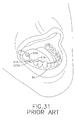
- To avoid the disadvantages of the conventional dental treatment, dental implantation is used to substitute for the treatment. With reference Figs. 22 and 31, a method of dental implantation is drilling a bone cavity (623A) in an edentulous place of the jaw bone (6A) out of which a damaged tooth removed in a patient's mouth by drilling the edentulous place of the jaw bone (6A). Next, a dental implant (64A) made of titanium is inserted into the bone cavity (623A) and the wound of the bone cavity (623A) in the jaw bone is sutured. After the fixture is integrated, an abutment (65A) screwed on the dental implant (64A) and then a crown (66A) put on the abutment (65A). Since the dental implant (64A) and the abutment (65A) support the crown (66A), the crown (66A) can sustain the force of occlusion.
- The depth for which the dental implant (64A) is inserted into the jaw bone and the position in which the dental implant (64A) is located is critical to succeed in the fixed dental implantation. The correct arrangement of the dental implant (64A) is not only the position but also the angulation of the bone cavity (623A) opposite to the upper tooth or the lower tooth so a top (661A) of the crown (66A) fits the corresponding tooth. If the position or the angulation of the bone cavity (623A) is inaccurate, the crown (66A) will not fit the corresponding tooth.
- The bone cavity must precisely correspond to the dental implant. When the bone cavity is too small, the dental implant cannot be inserted into the bone cavity. When the bone cavity is overlarge, the dental implant cannot be positioned securely in the bone cavity. Therefore, a multiple sets of drills and resin guide bridges are used to enlarge the bone cavity step by step.
- With reference to Figs. 23 to 25 and 29, a dentist drills a first hole (62) in an edentulous place of a dental model (6) and inserts a first post (7) into the first hole (62). Wax or gypsum is filled in the gap of the teeth to block out the undercut. Then resin is coated on the edentulous place (61) and covers teeth adjacent to the edentulous place (61) to form a first resin guide bridge (8) with a first through hole (81). After the resin hardens, the dentist replaces the first post (7) with a first guide tube (9). The first guide tube (9) is longer than the through hole (81). A diameter of the first guide tube (9) corresponds to a diameter of a first drill bit (101) of a drilling device (10).
- With reference to Figs. 26 to 28, the dentist drills a hole (62) again to enlarge the first hole (62) in sequent to form a fourth hole (623) and manufactures a fourth resin guide bridge (8C) to obtain the multiple sets of the resin guide bridge (8, 8C) and guide tube (9, 93).
- With reference to Figs. 29 and 30, the dentist puts the first resin guide bridge (8) with the first guide tube (9) on an edentulous place (61A) and adjacent teeth on a patient's jaw bone (6A). Because an inner surface of the first resin guide bridge (9) corresponds to the edentulous place (61A) and the adjacent teeth, the first guide tube (9) is precisely located in a point which will be drilled to form a bone cavity (62) later. The dentist then drills the first bone cavity (62A) by the drilling device (10) with the first drill bit (101). Then the dentist takes away the first resin guide bridge (9) and puts a second resin guide bridge to enlarge the bone cavity with a second drill bit. A fourth resin guide bridge (8C) is put on the edentulous place (61A) and the teeth on the patient's jaw bone (6A) to drill a fourth bone cavity (623A) by a fourth drill bit (104) through a fourth guide tube (93), so the dental implant can be inserted into the bone cavity.
- However, the above method for implanting the dental implant has following disadvantages:
- 1. A drill bit of a drilling device must move over the bridge to follow the guide tube so that the patient needs to open mouth wider. A patient with a small mouth or having a damaged tooth in the posterior area suffers greatly from excessively opening his mouth to place the drilling device into the mouth.
- 2. The dentist needs to stop drilling the bone cavity to measure the depth of the bone cavity.
- 3. Manufacture of the resin guide bridge is complex because the dentist needs to repeatedly drill the hole and insert the different size of the posts into the holes to manufacture the resin guide bridge.
- 4.Lacks of outer irrigation may cause the temperature elevated, thus impacted the osteointegration of the implant.
- The objective of the present invention is to provide a positioning device for dental implant that can be conveniently to form a resin guide bridge and accurately positioning dental implant in a dental model and a jaw bone in a patient's mouth.
- To achieve the foregoing objective, a positioning device for a dental implant in accordance with the present invention has a post and multiple guides. The post is cylindrical and has a diameter corresponding to a diameter of a hole in a dental model. The guides are mounted detachably on the post and are semi-tubular tabs and each guide has an inner concave, an inner diameter, and an outer diameter. The guides are mounted concentrically one another.
- Other objectives, advantages and novel features of the invention will become more apparent from the following detailed description when taken in conjunction with the accompanying drawings.
-
- Fig. 1 is a perspective view of a positioning device for a dental implant in accordance with the present invention;
- Fig. 2 is a perspective view of a dental model with a hole corresponding to the positioning device in Fig. 1;
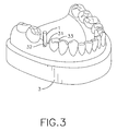
- Fig. 3 is an operational perspective view of the dental model with a post of the positioning device in Fig. 1 inserted into the hole in Fig. 2;
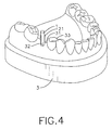
- Fig. 4 is an operational perspective view of a first guide attached to the post of the positioning device on the dental model in Fig. 3;
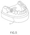
- Fig. 5 is an operational perspective view of a second guide attached to the first guide of the positioning device in Fig. 4;
- Fig. 6 is an operational perspective view of a third guide and a fourth guide attached sequentially to the second guide of the positioning device in Fig. 5;
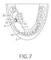
- Fig. 7 is a top view of the dental model coated with resin adjacent to the guides of the positioning device to form a resin guide bridge in Fig. 6;
- Fig. 8 is an operational perspective view of the resin guide bridge and the positioning device in Fig. 7 with the post removed;
- Fig. 9 is a perspective view of a fourth guide of the positioning device in Fig. 1 with multiple holes;
- Fig. 10 is an operational perspective view of the resin guide bridge with the guides of the positioning device put on a patient's jaw bone;
- Fig. 11 is an operational perspective view of a drilling device drilling a bone cavity in a patient's jaw bone in Fig. 10 through the first guide of the positioning device on the resin guide bridge;
- Fig. 12 is an operational perspective view of the patient's jaw bone with the finished bone cavity corresponding the first guide of the positioning device in Fig. 11;
- Fig. 13 is an operational perspective view of the drilling device enlarging the bone cavity on a patient's jaw bone through a fourth guide of the positioning device in Fig. 10;
- Fig. 14 is an exploded perspective view of a first guide attached to the post of the positioning device in Fig. 4;
- Fig. 15 is an operational perspective view of the dental model coated with resin in Fig. 14 adjacent to the first guide of the positioning device to form a first resin guide bridge;
- Fig. 16 is an operational perspective view of the resin guide bridge separating from the post and the first guide of the positioning device in Fig. 15;
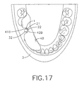
- Fig. 17 is an operational top view of the dental model coated with resin adjacent to the second guide of the positioning device to form a second resin guide bridge;
- Fig. 18 is an operational perspective view of the dental model coated with resin adjacent to the fourth guides to form a fourth resin guide bridge;
- Fig. 19 is an operational exploded perspective view of a drilling device drilling a bone cavity on a patient's jaw bone through the first guide of the positioning device;
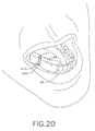
- Fig. 20 is an operational perspective view of the patient's jaw bone with the finished bone cavity corresponding to the first guide of the positioning device in Fig. 19;
- Fig. 21 is an operational perspective view of the drilling device enlarging the bone cavity on a patient's jaw bone in Fig. 20 through the fourth guide of the positioning device;
- Fig. 22 is an operational exploded perspective view of a patient's jaw bone with dental implants in accordance with the prior art;
- Fig. 23 is a perspective view of a dental model with first hole;
- Fig. 24 is a perspective view of the dental model with a post inserted into the hole in Fig. 23;
- Fig. 25 is a perspective view of the dental model in Fig. 24; coated with resin to form a first resin guide bridge;
- Fig. 26 is an exploded perspective view of a first placement resin guide bridge with a first guide tube;
- Fig. 27 is a perspective view of the dental model in Fig. 24 coated with resin to form a fourth resin guide bridge;
- Fig. 28 is an exploded perspective view of the fourth resin guide bridge and a fourth guide tube;
- Fig. 29 is an operational perspective view of the first resin guide bridge put on a patient's jaw bone in Fig. 22;
- Fig. 30 is an operational perspective view of the fourth resin guide bridge put on a patient's jaw bone in Fig. 29; and
- Fig. 31 is an operational perspective view of the patient's jaw bone in Fig. 30 with the finished bone cavity.
- With reference to Figs. 1 and 2, a positioning device for a dental implant in accordance with the present invention is used with a dental model (3) having a hole (32) defined in dental model (3). The positioning device comprises a post (1) and multiple guides (21, 22, 23, 24).
- The post (1) is cylindrical, comprises a diameter and may be made of magnetic material or permeable material. The diameter of the post (1) corresponds to a diameter of the hole (32) in the dental model (3).
- The guides (21, 22, 23, 24) are semi-tubular tabs, made of magnetic material and each guide(21, 22, 23, 24) comprises an inner concave, an inner diameter and an outer diameter. The guides(21, 22, 23, 24) are mounted detachably on the post (1) concentrically abuts one another according to their sizes. The inner diameter of an innermost guide (21) corresponds to the diameter of the post (1). The outer diameter of an inner one of any adjacent two of the guides (21, 22, 23, 24) corresponds to the inner diameter of an outer one of the adjacent two of the guides (21, 22, 23, 24). An outermost guide (24) may have at least one mounting hole (241) transversely defined through the outermost guide (24) as shown in Fig. 9.
- In a preferred embodiment, the guides (21, 22, 23, 24) may have a first guide (21), a second guide (22), a third guide (23) and a fourth guide (24).
- With reference to Figs. 2 and 3, a dental implantation is implemented with the positioning device. A dentist drills the hole (32) in an edentulous place (31) of the dental model (3) and inserts the post (1) into the hole (32). With further reference to Figs. 4 to 6, the post (1) is inserted into the hole (32) and the first guide (21) is attached to the post (1) so the inner concave of the first guide (21) faces outside the dental model (3). After positioning the first guide (21), the second guide (22) is attached to the first guide (21), the third guide (23) is attached to the second guide (22) and so on. Number of the guides (21, 22, 23, 24) matches number of times that a bone cavity in a patient's jaw bone is drilled.
- With reference to Figs. 7 and 8, wax or gypsum is filled in gaps between the teeth and grooves over the occlusal surface. Then, the dental model (3) is coated with resin on the edentulous place (31) and the teeth thereof to form a resin guide bridge (4) with an outside recess (41) which the post (1), the first guide (21), the second guide (22), the third guide (23) and the fourth guide (24) correspond to. After the resin is setting, a semi-tubular surface (42) is formed on the resin guide bridge (4) and corresponds to the post (1) with the guides (21, 22, 23, 24). The semi-tubular surface (42) can be coated with viscose to stick to the fourth guide (24) or bonded through the retention holes. With further reference to Fig. 9, the partially resin is filled into the mounting holes (241) in the fourth guide (24) so that the resin guide bridge (4) is combined securely with the fourth guide (24). Then the post (1) is removed from the resin guide bridge (4).
- With reference to Figs. 10 to 13, the resin guide bridge (4) with the first guide (21), the second guide (22), the third guide (23) and the fourth guide (24) puts on an edentulous place (31A) and adjacent teeth over the jaw bone (3A). Because an inner surface of the resin guide bridge (4) corresponds to the edentulous place (3 1 A) and the teeth thereof, the first guide (21) precisely points to a target on the jaw bone (3A) which will be drilled later. A dentist can drill the jaw bone (3A) along the first guide (21) to form the first bone cavity (32A) by a drilling device (5) with a first drill bit (51). Then the dentist removes the first guide (21) to expose the second guide (22) and drills and enlarges the bone cavity (3A) along the second guide (22) by an second drill bit having a diameter larger than that of the first drill bit (51). The dentist repetitively drills the bone cavity (32A) with different drill bits having increased diameters until the bone cavity (32D) is great enough to receive the dental implant (64A).
- Another dental implantation with the positioning device is described hereinafter.
- With reference to Fig. 14, the dentist drills the hole (32) in the edentulous place (31) in the dental model and inserts the post (1) into the hole (32). The first guide (21) is attached to the post (1) with the inner concave of the first guide (21) facing outside the dental model (3).
- With reference to Figs. 15 and 16, wax or gypsum is filled into the gap of the teeth. Then the dental model (3) is coated with resin on the edentulous place (33) and the teeth of the dental model (3) to form a first resin guide bridge (4A) with an outside recess (41A) corresponding to the post (1) and the first guide (21). After the resin hardens, a semi-tubular surface is formed on the first resin guide bridge (4A) and corresponds to the post (1) and the first guide (21). Then the dentist takes the first resin guide bridge (4A) away from the dental model (3) and removes the post (1) and the first guide (21) from the first resin guide bridge (4A).
- With further reference to Figs. 17 and 18, the post (1) with the first guide (21) inserts into the hole (32) again. The second guide (22) is attached to the first guide (21) to manufacture a second resin guide bridge (4B) by the same means used to manufacture the first resin guide bridge (4A). Then the first guide (21), the second guide (22), the third guide (23) and the fourth guide (24) are mounted respectively in corresponding resin guide bridges (4A, 4B, 4D).
- With reference to Figs. 19 to 21, the dentist puts the first resin guide bridge (4A) with the first guide (21) on the patient's jaw bone (3A) and drill the bone cavity (32A). The dentist repetitively drills and enlarges the bone cavity (32A) by replacing the resin guide bridge (4B, 4D) and the drill bit until the bone cavity (32D) is great enough to receive the dental implant (64A).
- The present invention has following advantages:
- 1. The drill bit of the drilling device can horizontally move into the outside recess to drill a bone cavity according to the guides. Therefore, the drill needn't move over the resin guide bridge to drill a bone cavity according to the guides. So a patient with a small mouth or being treated in the posterior place does not have to excessively open his mouth when experiencing the dental implantation. Therefore, the patient suffers less pain and pressure during the period of the dental implantation.
- 2. The dentist can directly look at the drill bit in the outside recess to identify the depth of the bone cavity.
- 3. Manufacture of the resin guide bridge is simple because the dentist needn't repeatedly drill the holes and insert the different size of the posts into the holes to manufacture the resin guide bridges.
- 4. In dental clinics, using single resin guide bridge and multiple guides to complete surgery is convenient.
- 5.Owing to the opening device of the guide, the external irrigation can be done during drilling. Thus preventing bone necrosis from over heating.
- Even though numerous characteristics and advantages of the present invention have been set forth in the foregoing description, together with details of the structure and features of the invention, the disclosure is illustrative only. Changes may be made in the details, especially in matters of shape, size, and arrangement of parts within the principles of the invention to the full extent indicated by the broad general meaning of the terms in which the appended claims are expressed.
Claims (6)
- A positioning device for dental implant comprisinga post (1) being cylindrical and comprising a diameter adapted to correspond to a diameter of a hole in a dental model; andmultiple guides (21, 22, 23, 24) being semi-tubular tabs, detachablymounted on the post (1) and each guide (21, 22, 23, 24) comprisingwherein the guides (21, 22, 23, 24) concentrically abut with each other and the inner diameter of an innermost one of the guides (21, 22, 23, 24) corresponds to the diameter of the post (1) and the outer diameter of an inner one of any adjacent two of the guides (21, 22, 23, 24) corresponds to the inner diameter of an outer one of the adjacent two of the guides (21, 22, 23, 24).an inner concave;an inner diameter; andan outer diameter; and
- The positioning device for dental implant as claimed in claim 1, wherein the post (1) is made of magnetic material.
- The positioning device for dental implant as claimed in claim 1, wherein the post (1) is made of permeable material.
- The positioning device for dental implant as claimed in claim 1, wherein the guides (21, 22, 23, 24) are made of magnetic material.
- The positioning device for dental implant as claimed in claim 1, wherein the outermost one of the guides (21, 22, 23, 24) further has at least one mounting hole defined transversely through the outermost one of the guides (21, 22,23,24).
- The positioning device for dental implant as claimed in claim 4, wherein the outermost one of the guides (21, 22, 23, 24) further has at least one mounting hole defined transversely through the outermost one of the guides.
Priority Applications (3)
| Application Number | Priority Date | Filing Date | Title |
|---|---|---|---|
| DE602006011618T DE602006011618D1 (en) | 2006-09-15 | 2006-09-15 | Positioning device for dental implant |
| EP06019299A EP1900338B1 (en) | 2006-09-15 | 2006-09-15 | Positioning device for dental implant |
| AT06019299T ATE454100T1 (en) | 2006-09-15 | 2006-09-15 | POSITIONING DEVICE FOR DENTAL IMPLANT |
Applications Claiming Priority (1)
| Application Number | Priority Date | Filing Date | Title |
|---|---|---|---|
| EP06019299A EP1900338B1 (en) | 2006-09-15 | 2006-09-15 | Positioning device for dental implant |
Publications (2)
| Publication Number | Publication Date |
|---|---|
| EP1900338A1 true EP1900338A1 (en) | 2008-03-19 |
| EP1900338B1 EP1900338B1 (en) | 2010-01-06 |
Family
ID=37708261
Family Applications (1)
| Application Number | Title | Priority Date | Filing Date |
|---|---|---|---|
| EP06019299A Not-in-force EP1900338B1 (en) | 2006-09-15 | 2006-09-15 | Positioning device for dental implant |
Country Status (3)
| Country | Link |
|---|---|
| EP (1) | EP1900338B1 (en) |
| AT (1) | ATE454100T1 (en) |
| DE (1) | DE602006011618D1 (en) |
Cited By (8)
| Publication number | Priority date | Publication date | Assignee | Title |
|---|---|---|---|---|
| AU2007203500B2 (en) * | 2007-07-26 | 2009-04-23 | Hsieh-Hsing Lin | Positioning device for dental implant |
| WO2010091839A1 (en) * | 2009-02-13 | 2010-08-19 | Armin Solbrig | Guide sleeve for guiding an oral-surgical drill and drilling template with such a sleeve |
| WO2013098418A1 (en) * | 2011-12-29 | 2013-07-04 | Swissmeda Ag | Surgical template for performing dental implantology |
| CH708017A1 (en) * | 2013-04-16 | 2014-10-31 | Dominik Meier | Processing System of Oral Implantology. |
| US9113982B1 (en) | 2014-03-19 | 2015-08-25 | GRS Guide System, Inc. | Positioning and installing surgical drilling devices and related devices and systems |
| US9211165B2 (en) | 2014-03-19 | 2015-12-15 | GRS Guide System, Inc. | Positioning and installing surgical drilling devices and related devices and systems |
| JP2018089469A (en) * | 2018-03-14 | 2018-06-14 | 株式会社DentalBank | Guide instrument for using dental cutting apparatus |
| WO2019064038A1 (en) * | 2017-09-29 | 2019-04-04 | Эмиль Рустам Оглы ИБРАГИМ | Guide sleeve with interior cooling for guided dental implantation |
Citations (5)
| Publication number | Priority date | Publication date | Assignee | Title |
|---|---|---|---|---|
| US5743916A (en) * | 1990-07-13 | 1998-04-28 | Human Factors Industrial Design, Inc. | Drill guide with removable ferrules |
| US5833693A (en) * | 1997-05-02 | 1998-11-10 | Abrahami; Israel | Drill guide |
| US5888065A (en) * | 1998-07-30 | 1999-03-30 | Sussman; Harold I. | Dental implant hole guide arrangement |
| US5989025A (en) * | 1996-05-22 | 1999-11-23 | Conley; Roy | Drill guide |
| US20050106531A1 (en) * | 2003-11-14 | 2005-05-19 | Brian Tang | Thermoplastic surgical template for performing dental implant osteotomies and method thereof |
-
2006
- 2006-09-15 DE DE602006011618T patent/DE602006011618D1/en active Active
- 2006-09-15 EP EP06019299A patent/EP1900338B1/en not_active Not-in-force
- 2006-09-15 AT AT06019299T patent/ATE454100T1/en not_active IP Right Cessation
Patent Citations (5)
| Publication number | Priority date | Publication date | Assignee | Title |
|---|---|---|---|---|
| US5743916A (en) * | 1990-07-13 | 1998-04-28 | Human Factors Industrial Design, Inc. | Drill guide with removable ferrules |
| US5989025A (en) * | 1996-05-22 | 1999-11-23 | Conley; Roy | Drill guide |
| US5833693A (en) * | 1997-05-02 | 1998-11-10 | Abrahami; Israel | Drill guide |
| US5888065A (en) * | 1998-07-30 | 1999-03-30 | Sussman; Harold I. | Dental implant hole guide arrangement |
| US20050106531A1 (en) * | 2003-11-14 | 2005-05-19 | Brian Tang | Thermoplastic surgical template for performing dental implant osteotomies and method thereof |
Cited By (8)
| Publication number | Priority date | Publication date | Assignee | Title |
|---|---|---|---|---|
| AU2007203500B2 (en) * | 2007-07-26 | 2009-04-23 | Hsieh-Hsing Lin | Positioning device for dental implant |
| WO2010091839A1 (en) * | 2009-02-13 | 2010-08-19 | Armin Solbrig | Guide sleeve for guiding an oral-surgical drill and drilling template with such a sleeve |
| WO2013098418A1 (en) * | 2011-12-29 | 2013-07-04 | Swissmeda Ag | Surgical template for performing dental implantology |
| CH708017A1 (en) * | 2013-04-16 | 2014-10-31 | Dominik Meier | Processing System of Oral Implantology. |
| US9113982B1 (en) | 2014-03-19 | 2015-08-25 | GRS Guide System, Inc. | Positioning and installing surgical drilling devices and related devices and systems |
| US9211165B2 (en) | 2014-03-19 | 2015-12-15 | GRS Guide System, Inc. | Positioning and installing surgical drilling devices and related devices and systems |
| WO2019064038A1 (en) * | 2017-09-29 | 2019-04-04 | Эмиль Рустам Оглы ИБРАГИМ | Guide sleeve with interior cooling for guided dental implantation |
| JP2018089469A (en) * | 2018-03-14 | 2018-06-14 | 株式会社DentalBank | Guide instrument for using dental cutting apparatus |
Also Published As
| Publication number | Publication date |
|---|---|
| EP1900338B1 (en) | 2010-01-06 |
| DE602006011618D1 (en) | 2010-02-25 |
| ATE454100T1 (en) | 2010-01-15 |
Similar Documents
| Publication | Publication Date | Title |
|---|---|---|
| US7322821B1 (en) | Positioning device for dental implant | |
| US6312258B1 (en) | Kit for immediate post-extraction implantation | |
| US5915962A (en) | Dental implant and prosthesis positioning | |
| EP1900338B1 (en) | Positioning device for dental implant | |
| Froum et al. | The use of transitional implants for immediate fixed temporary prostheses in cases of implant restorations | |
| US7429175B2 (en) | Dental implant surgical guide | |
| US4568285A (en) | Mastication force dampening dental jawbone implant | |
| US20080057467A1 (en) | Dental Implant Surgical Guide | |
| JP2005518868A (en) | Implant positioning apparatus and method | |
| US8333587B2 (en) | GRS implant drilling guide | |
| KR200476682Y1 (en) | guide stent for placing dental implants | |
| JP2004521671A (en) | Positioning device for providing an implant-supported denture | |
| US8858228B2 (en) | Method and kit for dental implant drilling guides | |
| US20070099152A1 (en) | Dental implant system | |
| KR101385882B1 (en) | Universal surgical guide kit for dental implant placement | |
| US20030044749A1 (en) | Stable dental analog systems | |
| KR101763763B1 (en) | Apparatus for guiding implant position | |
| KR20190048683A (en) | Surgical guide for implant surgery | |
| KR101453775B1 (en) | Surgical apparatus implant kit for accurate implant precision guiding | |
| KR101516950B1 (en) | apparatus for abutment profile drill | |
| KR101516949B1 (en) | apparatus for bone flattening drill | |
| AU2007203500B2 (en) | Positioning device for dental implant | |
| JP4619376B2 (en) | Artificial root positioning device | |
| KR20210001632A (en) | Dental drill guiding device | |
| KR20200069744A (en) | trephine drill for implant |
Legal Events
| Date | Code | Title | Description |
|---|---|---|---|
| PUAI | Public reference made under article 153(3) epc to a published international application that has entered the european phase |
Free format text: ORIGINAL CODE: 0009012 |
|
| 17P | Request for examination filed |
Effective date: 20070523 |
|
| AK | Designated contracting states |
Kind code of ref document: A1 Designated state(s): AT BE BG CH CY CZ DE DK EE ES FI FR GB GR HU IE IS IT LI LT LU LV MC NL PL PT RO SE SI SK TR |
|
| AX | Request for extension of the european patent |
Extension state: AL BA HR MK YU |
|
| AKX | Designation fees paid |
Designated state(s): AT BE BG CH CY CZ DE DK EE ES FI FR GB GR HU IE IS IT LI LT LU LV MC NL PL PT RO SE SI SK TR |
|
| GRAP | Despatch of communication of intention to grant a patent |
Free format text: ORIGINAL CODE: EPIDOSNIGR1 |
|
| GRAS | Grant fee paid |
Free format text: ORIGINAL CODE: EPIDOSNIGR3 |
|
| GRAA | (expected) grant |
Free format text: ORIGINAL CODE: 0009210 |
|
| AK | Designated contracting states |
Kind code of ref document: B1 Designated state(s): AT BE BG CH CY CZ DE DK EE ES FI FR GB GR HU IE IS IT LI LT LU LV MC NL PL PT RO SE SI SK TR |
|
| REG | Reference to a national code |
Ref country code: GB Ref legal event code: FG4D |
|
| REG | Reference to a national code |
Ref country code: CH Ref legal event code: EP Ref country code: CH Ref legal event code: NV Representative=s name: ISLER & PEDRAZZINI AG |
|
| REG | Reference to a national code |
Ref country code: IE Ref legal event code: FG4D |
|
| REG | Reference to a national code |
Ref country code: SE Ref legal event code: TRGR |
|
| REF | Corresponds to: |
Ref document number: 602006011618 Country of ref document: DE Date of ref document: 20100225 Kind code of ref document: P |
|
| REG | Reference to a national code |
Ref country code: NL Ref legal event code: VDEP Effective date: 20100106 |
|
| PG25 | Lapsed in a contracting state [announced via postgrant information from national office to epo] |
Ref country code: SI Free format text: LAPSE BECAUSE OF FAILURE TO SUBMIT A TRANSLATION OF THE DESCRIPTION OR TO PAY THE FEE WITHIN THE PRESCRIBED TIME-LIMIT Effective date: 20100106 |
|
| LTIE | Lt: invalidation of european patent or patent extension |
Effective date: 20100106 |
|
| PG25 | Lapsed in a contracting state [announced via postgrant information from national office to epo] |
Ref country code: AT Free format text: LAPSE BECAUSE OF FAILURE TO SUBMIT A TRANSLATION OF THE DESCRIPTION OR TO PAY THE FEE WITHIN THE PRESCRIBED TIME-LIMIT Effective date: 20100106 |
|
| PG25 | Lapsed in a contracting state [announced via postgrant information from national office to epo] |
Ref country code: PT Free format text: LAPSE BECAUSE OF FAILURE TO SUBMIT A TRANSLATION OF THE DESCRIPTION OR TO PAY THE FEE WITHIN THE PRESCRIBED TIME-LIMIT Effective date: 20100506 Ref country code: LT Free format text: LAPSE BECAUSE OF FAILURE TO SUBMIT A TRANSLATION OF THE DESCRIPTION OR TO PAY THE FEE WITHIN THE PRESCRIBED TIME-LIMIT Effective date: 20100106 Ref country code: NL Free format text: LAPSE BECAUSE OF FAILURE TO SUBMIT A TRANSLATION OF THE DESCRIPTION OR TO PAY THE FEE WITHIN THE PRESCRIBED TIME-LIMIT Effective date: 20100106 Ref country code: ES Free format text: LAPSE BECAUSE OF FAILURE TO SUBMIT A TRANSLATION OF THE DESCRIPTION OR TO PAY THE FEE WITHIN THE PRESCRIBED TIME-LIMIT Effective date: 20100417 Ref country code: IS Free format text: LAPSE BECAUSE OF FAILURE TO SUBMIT A TRANSLATION OF THE DESCRIPTION OR TO PAY THE FEE WITHIN THE PRESCRIBED TIME-LIMIT Effective date: 20100506 |
|
| PG25 | Lapsed in a contracting state [announced via postgrant information from national office to epo] |
Ref country code: LV Free format text: LAPSE BECAUSE OF FAILURE TO SUBMIT A TRANSLATION OF THE DESCRIPTION OR TO PAY THE FEE WITHIN THE PRESCRIBED TIME-LIMIT Effective date: 20100106 Ref country code: FI Free format text: LAPSE BECAUSE OF FAILURE TO SUBMIT A TRANSLATION OF THE DESCRIPTION OR TO PAY THE FEE WITHIN THE PRESCRIBED TIME-LIMIT Effective date: 20100106 Ref country code: PL Free format text: LAPSE BECAUSE OF FAILURE TO SUBMIT A TRANSLATION OF THE DESCRIPTION OR TO PAY THE FEE WITHIN THE PRESCRIBED TIME-LIMIT Effective date: 20100106 |
|
| PG25 | Lapsed in a contracting state [announced via postgrant information from national office to epo] |
Ref country code: BE Free format text: LAPSE BECAUSE OF FAILURE TO SUBMIT A TRANSLATION OF THE DESCRIPTION OR TO PAY THE FEE WITHIN THE PRESCRIBED TIME-LIMIT Effective date: 20100106 Ref country code: GR Free format text: LAPSE BECAUSE OF FAILURE TO SUBMIT A TRANSLATION OF THE DESCRIPTION OR TO PAY THE FEE WITHIN THE PRESCRIBED TIME-LIMIT Effective date: 20100407 Ref country code: RO Free format text: LAPSE BECAUSE OF FAILURE TO SUBMIT A TRANSLATION OF THE DESCRIPTION OR TO PAY THE FEE WITHIN THE PRESCRIBED TIME-LIMIT Effective date: 20100106 Ref country code: CY Free format text: LAPSE BECAUSE OF FAILURE TO SUBMIT A TRANSLATION OF THE DESCRIPTION OR TO PAY THE FEE WITHIN THE PRESCRIBED TIME-LIMIT Effective date: 20100106 Ref country code: EE Free format text: LAPSE BECAUSE OF FAILURE TO SUBMIT A TRANSLATION OF THE DESCRIPTION OR TO PAY THE FEE WITHIN THE PRESCRIBED TIME-LIMIT Effective date: 20100106 |
|
| PLBE | No opposition filed within time limit |
Free format text: ORIGINAL CODE: 0009261 |
|
| STAA | Information on the status of an ep patent application or granted ep patent |
Free format text: STATUS: NO OPPOSITION FILED WITHIN TIME LIMIT |
|
| PG25 | Lapsed in a contracting state [announced via postgrant information from national office to epo] |
Ref country code: SK Free format text: LAPSE BECAUSE OF FAILURE TO SUBMIT A TRANSLATION OF THE DESCRIPTION OR TO PAY THE FEE WITHIN THE PRESCRIBED TIME-LIMIT Effective date: 20100106 Ref country code: BG Free format text: LAPSE BECAUSE OF FAILURE TO SUBMIT A TRANSLATION OF THE DESCRIPTION OR TO PAY THE FEE WITHIN THE PRESCRIBED TIME-LIMIT Effective date: 20100406 Ref country code: CZ Free format text: LAPSE BECAUSE OF FAILURE TO SUBMIT A TRANSLATION OF THE DESCRIPTION OR TO PAY THE FEE WITHIN THE PRESCRIBED TIME-LIMIT Effective date: 20100106 |
|
| 26N | No opposition filed |
Effective date: 20101007 |
|
| PG25 | Lapsed in a contracting state [announced via postgrant information from national office to epo] |
Ref country code: DK Free format text: LAPSE BECAUSE OF FAILURE TO SUBMIT A TRANSLATION OF THE DESCRIPTION OR TO PAY THE FEE WITHIN THE PRESCRIBED TIME-LIMIT Effective date: 20100106 |
|
| PG25 | Lapsed in a contracting state [announced via postgrant information from national office to epo] |
Ref country code: IT Free format text: LAPSE BECAUSE OF FAILURE TO SUBMIT A TRANSLATION OF THE DESCRIPTION OR TO PAY THE FEE WITHIN THE PRESCRIBED TIME-LIMIT Effective date: 20100106 |
|
| PG25 | Lapsed in a contracting state [announced via postgrant information from national office to epo] |
Ref country code: MC Free format text: LAPSE BECAUSE OF NON-PAYMENT OF DUE FEES Effective date: 20100930 |
|
| PG25 | Lapsed in a contracting state [announced via postgrant information from national office to epo] |
Ref country code: IE Free format text: LAPSE BECAUSE OF NON-PAYMENT OF DUE FEES Effective date: 20100915 |
|
| PG25 | Lapsed in a contracting state [announced via postgrant information from national office to epo] |
Ref country code: LU Free format text: LAPSE BECAUSE OF NON-PAYMENT OF DUE FEES Effective date: 20100915 Ref country code: HU Free format text: LAPSE BECAUSE OF FAILURE TO SUBMIT A TRANSLATION OF THE DESCRIPTION OR TO PAY THE FEE WITHIN THE PRESCRIBED TIME-LIMIT Effective date: 20100707 |
|
| PG25 | Lapsed in a contracting state [announced via postgrant information from national office to epo] |
Ref country code: TR Free format text: LAPSE BECAUSE OF FAILURE TO SUBMIT A TRANSLATION OF THE DESCRIPTION OR TO PAY THE FEE WITHIN THE PRESCRIBED TIME-LIMIT Effective date: 20100106 |
|
| PGFP | Annual fee paid to national office [announced via postgrant information from national office to epo] |
Ref country code: CH Payment date: 20140922 Year of fee payment: 9 |
|
| PGFP | Annual fee paid to national office [announced via postgrant information from national office to epo] |
Ref country code: GB Payment date: 20140923 Year of fee payment: 9 Ref country code: SE Payment date: 20140923 Year of fee payment: 9 |
|
| PGFP | Annual fee paid to national office [announced via postgrant information from national office to epo] |
Ref country code: FR Payment date: 20140917 Year of fee payment: 9 |
|
| REG | Reference to a national code |
Ref country code: CH Ref legal event code: PL |
|
| REG | Reference to a national code |
Ref country code: SE Ref legal event code: EUG |
|
| GBPC | Gb: european patent ceased through non-payment of renewal fee |
Effective date: 20150915 |
|
| PG25 | Lapsed in a contracting state [announced via postgrant information from national office to epo] |
Ref country code: SE Free format text: LAPSE BECAUSE OF NON-PAYMENT OF DUE FEES Effective date: 20150916 |
|
| REG | Reference to a national code |
Ref country code: FR Ref legal event code: ST Effective date: 20160531 |
|
| PG25 | Lapsed in a contracting state [announced via postgrant information from national office to epo] |
Ref country code: GB Free format text: LAPSE BECAUSE OF NON-PAYMENT OF DUE FEES Effective date: 20150915 Ref country code: CH Free format text: LAPSE BECAUSE OF NON-PAYMENT OF DUE FEES Effective date: 20150930 Ref country code: LI Free format text: LAPSE BECAUSE OF NON-PAYMENT OF DUE FEES Effective date: 20150930 |
|
| PG25 | Lapsed in a contracting state [announced via postgrant information from national office to epo] |
Ref country code: FR Free format text: LAPSE BECAUSE OF NON-PAYMENT OF DUE FEES Effective date: 20150930 |
|
| PGFP | Annual fee paid to national office [announced via postgrant information from national office to epo] |
Ref country code: DE Payment date: 20161110 Year of fee payment: 11 |
|
| REG | Reference to a national code |
Ref country code: DE Ref legal event code: R119 Ref document number: 602006011618 Country of ref document: DE |
|
| PG25 | Lapsed in a contracting state [announced via postgrant information from national office to epo] |
Ref country code: DE Free format text: LAPSE BECAUSE OF NON-PAYMENT OF DUE FEES Effective date: 20180404 |