EP1899657B1 - Dehumidifier - Google Patents
Dehumidifier Download PDFInfo
- Publication number
- EP1899657B1 EP1899657B1 EP06768829.1A EP06768829A EP1899657B1 EP 1899657 B1 EP1899657 B1 EP 1899657B1 EP 06768829 A EP06768829 A EP 06768829A EP 1899657 B1 EP1899657 B1 EP 1899657B1
- Authority
- EP
- European Patent Office
- Prior art keywords
- air
- dehumidifier
- assembly
- case
- desiccant
- Prior art date
- Legal status (The legal status is an assumption and is not a legal conclusion. Google has not performed a legal analysis and makes no representation as to the accuracy of the status listed.)
- Not-in-force
Links
Images


Classifications
-
- B—PERFORMING OPERATIONS; TRANSPORTING
- B01—PHYSICAL OR CHEMICAL PROCESSES OR APPARATUS IN GENERAL
- B01D—SEPARATION
- B01D53/00—Separation of gases or vapours; Recovering vapours of volatile solvents from gases; Chemical or biological purification of waste gases, e.g. engine exhaust gases, smoke, fumes, flue gases, aerosols
- B01D53/02—Separation of gases or vapours; Recovering vapours of volatile solvents from gases; Chemical or biological purification of waste gases, e.g. engine exhaust gases, smoke, fumes, flue gases, aerosols by adsorption, e.g. preparative gas chromatography
- B01D53/06—Separation of gases or vapours; Recovering vapours of volatile solvents from gases; Chemical or biological purification of waste gases, e.g. engine exhaust gases, smoke, fumes, flue gases, aerosols by adsorption, e.g. preparative gas chromatography with moving adsorbents, e.g. rotating beds
-
- B—PERFORMING OPERATIONS; TRANSPORTING
- B01—PHYSICAL OR CHEMICAL PROCESSES OR APPARATUS IN GENERAL
- B01D—SEPARATION
- B01D53/00—Separation of gases or vapours; Recovering vapours of volatile solvents from gases; Chemical or biological purification of waste gases, e.g. engine exhaust gases, smoke, fumes, flue gases, aerosols
- B01D53/26—Drying gases or vapours
- B01D53/261—Drying gases or vapours by adsorption
-
- B—PERFORMING OPERATIONS; TRANSPORTING
- B01—PHYSICAL OR CHEMICAL PROCESSES OR APPARATUS IN GENERAL
- B01D—SEPARATION
- B01D53/00—Separation of gases or vapours; Recovering vapours of volatile solvents from gases; Chemical or biological purification of waste gases, e.g. engine exhaust gases, smoke, fumes, flue gases, aerosols
- B01D53/26—Drying gases or vapours
- B01D53/265—Drying gases or vapours by refrigeration (condensation)
-
- F—MECHANICAL ENGINEERING; LIGHTING; HEATING; WEAPONS; BLASTING
- F24—HEATING; RANGES; VENTILATING
- F24F—AIR-CONDITIONING; AIR-HUMIDIFICATION; VENTILATION; USE OF AIR CURRENTS FOR SCREENING
- F24F3/00—Air-conditioning systems in which conditioned primary air is supplied from one or more central stations to distributing units in the rooms or spaces where it may receive secondary treatment; Apparatus specially designed for such systems
- F24F3/12—Air-conditioning systems in which conditioned primary air is supplied from one or more central stations to distributing units in the rooms or spaces where it may receive secondary treatment; Apparatus specially designed for such systems characterised by the treatment of the air otherwise than by heating and cooling
- F24F3/14—Air-conditioning systems in which conditioned primary air is supplied from one or more central stations to distributing units in the rooms or spaces where it may receive secondary treatment; Apparatus specially designed for such systems characterised by the treatment of the air otherwise than by heating and cooling by humidification; by dehumidification
- F24F3/1411—Air-conditioning systems in which conditioned primary air is supplied from one or more central stations to distributing units in the rooms or spaces where it may receive secondary treatment; Apparatus specially designed for such systems characterised by the treatment of the air otherwise than by heating and cooling by humidification; by dehumidification by absorbing or adsorbing water, e.g. using an hygroscopic desiccant
- F24F3/1423—Air-conditioning systems in which conditioned primary air is supplied from one or more central stations to distributing units in the rooms or spaces where it may receive secondary treatment; Apparatus specially designed for such systems characterised by the treatment of the air otherwise than by heating and cooling by humidification; by dehumidification by absorbing or adsorbing water, e.g. using an hygroscopic desiccant with a moving bed of solid desiccants, e.g. a rotary wheel supporting solid desiccants
-
- B—PERFORMING OPERATIONS; TRANSPORTING
- B01—PHYSICAL OR CHEMICAL PROCESSES OR APPARATUS IN GENERAL
- B01D—SEPARATION
- B01D2259/00—Type of treatment
- B01D2259/40—Further details for adsorption processes and devices
- B01D2259/40083—Regeneration of adsorbents in processes other than pressure or temperature swing adsorption
- B01D2259/40088—Regeneration of adsorbents in processes other than pressure or temperature swing adsorption by heating
- B01D2259/4009—Regeneration of adsorbents in processes other than pressure or temperature swing adsorption by heating using hot gas
-
- F—MECHANICAL ENGINEERING; LIGHTING; HEATING; WEAPONS; BLASTING
- F24—HEATING; RANGES; VENTILATING
- F24F—AIR-CONDITIONING; AIR-HUMIDIFICATION; VENTILATION; USE OF AIR CURRENTS FOR SCREENING
- F24F2203/00—Devices or apparatus used for air treatment
- F24F2203/10—Rotary wheel
- F24F2203/1012—Details of the casing or cover
-
- F—MECHANICAL ENGINEERING; LIGHTING; HEATING; WEAPONS; BLASTING
- F24—HEATING; RANGES; VENTILATING
- F24F—AIR-CONDITIONING; AIR-HUMIDIFICATION; VENTILATION; USE OF AIR CURRENTS FOR SCREENING
- F24F2203/00—Devices or apparatus used for air treatment
- F24F2203/10—Rotary wheel
- F24F2203/1032—Desiccant wheel
-
- F—MECHANICAL ENGINEERING; LIGHTING; HEATING; WEAPONS; BLASTING
- F24—HEATING; RANGES; VENTILATING
- F24F—AIR-CONDITIONING; AIR-HUMIDIFICATION; VENTILATION; USE OF AIR CURRENTS FOR SCREENING
- F24F2203/00—Devices or apparatus used for air treatment
- F24F2203/10—Rotary wheel
- F24F2203/1056—Rotary wheel comprising a reheater
- F24F2203/106—Electrical reheater
-
- F—MECHANICAL ENGINEERING; LIGHTING; HEATING; WEAPONS; BLASTING
- F24—HEATING; RANGES; VENTILATING
- F24F—AIR-CONDITIONING; AIR-HUMIDIFICATION; VENTILATION; USE OF AIR CURRENTS FOR SCREENING
- F24F2203/00—Devices or apparatus used for air treatment
- F24F2203/10—Rotary wheel
- F24F2203/1068—Rotary wheel comprising one rotor
-
- F—MECHANICAL ENGINEERING; LIGHTING; HEATING; WEAPONS; BLASTING
- F24—HEATING; RANGES; VENTILATING
- F24F—AIR-CONDITIONING; AIR-HUMIDIFICATION; VENTILATION; USE OF AIR CURRENTS FOR SCREENING
- F24F2203/00—Devices or apparatus used for air treatment
- F24F2203/10—Rotary wheel
- F24F2203/1084—Rotary wheel comprising two flow rotor segments
Description
- The present invention relates to dehumidifiers, and more particularly, to a dehumidifier, in which moisture is adsorbed, not by refrigerant, but by desiccant to collect the moisture separately, for improving dehumidifying efficiency.
- In general, the dehumidifier reduces humidity of a room by drawing humid air from the room, making the humid air to pass through a heat exchanger having a condenser and an evaporator through which refrigerant flows to remove moisture from the air, and discharging the air having the moisture removed therefrom, again.
- That is, the dehumidifier takes heat from air around it by vaporizing liquid refrigerant at the evaporator. In more detail, a temperature of the evaporator drops as the refrigerant vaporizes, and as the air passes through the evaporator, a temperature of the air also drops.
- As the temperature around the evaporator drops, the moisture in the air condenses, to form dew on a surface of the evaporator.
-
FIG. 1 illustrates a diagram of a related art dehumidifier. - Referring to
FIG. 1 , the related art dehumidifier is provided with a cabinet 1 having an inlet (not shown) for drawing room air, afilter 2 mounted on an inlet side, a heat exchanger 3 in front of thefilter 2 on the cabinet 1 for heat exchange with the room air to dehumidify the room air, afan assembly 4 in front of the heat exchanger 3 for forced circulation of the room air, a water tank 6 under the heat exchanger for collecting condensed water, and afront panel 5, a frontal exterior of the dehumidifier, having anoutlet 5a. - However, the related art dehumidifier has the following problems.
- The
outlet 5a in thefront panel 5 provides a poor outer appearance, and is difficult to change a direction of discharge of the air. - Since the water tank 6 can be mounted/dismounted through a rear of the cabinet 1, the mounting/dismounting of the water tank 6 is not convenient.
- Because the room air passed through the heat exchanger 3 is discharged to the room again directly even if the moisture is not removed from the air fully, the dehumidifying efficiency is poor.
- Moreover, the use of the compressor in the related art humidifier for circulation of the refrigerant leads a production cost high, and causes much noise and vibration during operation.
-
EP 1 515 096 ,CN 2300029Y ,GB 2 333 722EP 0 693 660 relate to dehumidifiers provided with a rotating desiccant wheel and an associated desiccant regeneration cycle. - Accordingly, the present invention is directed to a dehumidifier that substantially obviates one or more problems due to limitations and disadvantages of the related art.
- It would be desirable to provide a dehumidifier which has a high de-humidifying efficiency, low cost, and very low noise and vibration.
- It would also be desirable to provide a dehumidifier which has a good outer appearance, and water tank for holding dehumidified water mounting/dismounting of which is easy.
- Additional advantages, objects, and features of the invention will be set forth in part in the description which follows and in part will become apparent to those having ordinary skill in the art upon examination of the following or may be learned from practice of the invention. The objectives and other advantages of the invention may be realized and attained by the structure particularly pointed out in the written description and claims hereof as well as the appended drawings.
- The invention provides a dehumidifier as set out in the appended claims.
- Embodiments of the invention provide a dehumidifier which includes a case, inlets passed through the case for introduction of air from an outside of the case to an inside of the case, an outlet formed to pass through a top of the case for discharging air dehumidified in the case to the outside of the case, a desiccant assembly for absorbing moisture from air drawn into the case, a blower assembly for drawing air through the inlets and blowing the air to the outlet, a regenerator assembly for blowing hot air to the desiccant assembly for drying the desiccant assembly, a heat exchanger for condensing high temperature, humid air blown by the regenerator assembly through the desiccant assembly, to separate the moisture from the air, and a water collecting assembly for collecting water condensed and separated from the air at the heat exchanger.
- Embodiments of the invention also provide a dehumidifier which includes a case, inlets passed through the case for introduction of air from an outside of the case to an inside of the case, an outlet formed to pass through a top of the case for discharging air dehumidified in the case to the outside of the case, a desiccant assembly including a desiccant member for absorbing moisture from air drawn into the case, a desiccant rotor rotatably mounted for housing the desiccant member, and a rotating unit for rotating the desiccant rotor, a blower assembly for forced drawing of air through the inlets and blowing the air to the outlet, a regenerator assembly including a regenerating fan for blowing air to the desiccant assembly, a regenerating motor for providing a rotating power to rotate the regenerating fan, and a heater for heating the air blown by the regenerating fan, for drying the desiccant assembly, a heat exchanger for condensing high temperature, humid air blown by the regenerator assembly through the desiccant assembly, to separate the moisture from the air, and a water collecting assembly for collecting water condensed and separated from the air at the heat exchanger.
- Embodiments of the invention also provide a dehumidifier which includes a case, inlets passed through the case for introduction of air from an outside of the case to an inside of the case, an outlet formed to pass through a top of the case for discharging air dehumidified in the case to the outside of the case, a desiccant assembly including a desiccant member for absorbing moisture from air drawn into the case, a desiccant rotor rotatably mounted for housing the desiccant member, and a rotating unit for rotating the desiccant rotor, a blower assembly for forced drawing of air through the inlets and blowing the air to the outlet, a regenerator assembly for blowing hot air to the desiccant assembly for drying the desiccant assembly, a heat exchanger for condensing high temperature, humid air blown by the regenerator assembly through the desiccant assembly, to separate the moisture from the air, and a water collecting assembly for collecting water condensed and separated from the air at the heat exchanger, wherein the regenerator assembly includes, a regenerating fan for blowing air toward the desiccant assembly, a regenerating fan housing for housing the regenerating fan, a regenerating motor for providing a rotating power to rotate the regenerating fan, a heater for heating the air blown by the regenerating fan, a heater case for casing the heater, having one side in communication with the regenerating fan housing, and the other side in communication with a portion of the desiccant assembly for guiding air from the regenerating fan to the desiccant member, a regenerating cover for guiding the air passed through the desiccant assembly by the regenerating fan to an inside of the heat exchanger, and a circulating duct for guiding the air passed through the heat exchanger to the regenerating fan.
- Thus, the dehumidifier of the present invention draws air room air through a front and a rear of the case, a lower side of a side of the case, or corners of one side of the case, and discharges upward of the case. Accordingly, since there is a room for utilizing the front or the rear of the dehumidifier, an exterior of a design the user desires can be provided.
- The provision of the desiccant assembly for keeping absorbing moisture from room air, and the regenerator assembly for keeping drying the desiccant member in the case permits to improve dehumidifying efficiency compared to the related art dehumidifier.
- The elimination of a compressor from the related art dehumidifier permits to reduce weight of the dehumidifier, as well as noise of the dehumidifier, to improve convenience of use of the dehumidifier.
- It is to be understood that both the foregoing general description and the following detailed description of the present invention are exemplary and explanatory and are intended to provide further explanation of the invention as claimed.
- The accompanying drawings, which are included to provide a further understanding of the invention and are incorporated in and constitute a part of this application, illustrate embodiment(s) of the invention and together with the description serve to explain the principle of the invention. In the drawings;
-
FIG. 1 illustrates an exploded perspective view of a related art dehumidifier; -
FIG. 2 illustrates a perspective view of a dehumidifier in accordance with a preferred embodiment of the present invention; -
FIG. 3 illustrates an exploded perspective view of the dehumidifier inFIG. 2 ; -
FIG. 4 illustrates a perspective view of a heat exchanger inFIG. 3 ; -
FIG. 5 illustrates a perspective view of the heat exchanger of the dehumidifier inFIG. 4 ; -
FIG. 6 illustrates a diagram showing operation of the dehumidifier inFIG. 2 ; -
FIG. 7 illustrates a perspective view of a variation of the dehumidifier inFIG. 2 ; -
FIG. 8 illustrates an exploded perspective view of the dehumidifier inFIG. 7 ; -
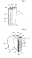
FIG. 9 illustrates a perspective view of a dehumidifier in accordance with another preferred embodiment of the present invention; -
FIG. 10 illustrates a perspective view of the dehumidifier inFIG. 9 with a front panel thereof opened; -
FIG. 11 illustrates a perspective view of the dehumidifier inFIG. 9 with a water tank thereof drawn out partially; -
FIG. 12 illustrates an exploded perspective view of the dehumidifier inFIG. 9 ; -
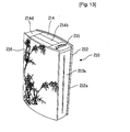
FIG. 13 illustrates a perspective view of a variation of the dehumidifier inFIG. 9 ; -
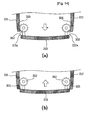
FIG. 14 illustrates sectional views of the dehumidifier inFIG. 13 ; -
FIG. 15 illustrates an exploded perspective view of the dehumidifier inFIG. 13 ; and -
FIG. 16 illustrates a perspective view of a variation of the dehumidifier inFIG. 13 with the side panel moved out. - Reference will now be made in detail to the preferred embodiments of the present invention, examples of which are illustrated in the accompanying drawings
FIGS. 2 to 6 . Wherever possible, the same reference numbers will be used throughout the drawings to refer to the same or like parts. - Referring to
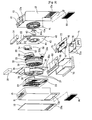
FIGS. 2 and3 , the dehumidifier includes acase 10 of an exterior of the dehumidifier, aheat exchanger 20 of a heat conductive material in thecase 10, adesiccant assembly 30 in thecase 10 for absorbing moisture from the air, ablower assembly 40 for forcing the room air to be drawn into thecase 10, and aregenerator assembly 50 for forced circulation of a portion of the room air drawn into thecase 10 through theheat exchanger 20. - The
case 10 has a hexahedral shape substantially, with a front half portion and a rear half portion. That is, thecase 10 includes afront frame 11 forming exteriors of a front, sides and a top of a front half of thecase 10, and arear frame 12 forming exteriors of a rear, sides and a top of the rear half of thecase 10. Thefront frame 11 and therear frame 12 have hexahedral shapes having a rear and a front thereof opened, respectively. - The
case 10 having thefront frame 11 and therear frame 12 hasinlets inlets front frame 11 and in a rear of therear frame 12, respectively. - The
inlets filters 80 mounted thereon, respectively. Thefilter 80, for filtering foreign matters from air, may include a single unit selected from a prefilter for filtering relatively large sized dust from the air drawn through theinlets - In front of the
front frame 11 having theinlet 11a, there is afront panel 16 for making a front exterior graceful. Thefront panel 16 has a shape of a rectangular plate with a size the same with thefront frame 11, coupled to a side of thefront frame 11 with hinges enabling to rotate in a side direction. - In a lower side of the
front panel 16, there is asuction grill 16a with a size in correspondence to theinlet 11a, in thefront frame 11. - On a top of the
front frame 11, there is atransparent display part 15 for displaying an operation state of the dehumidifier. Though not shown, there are a plurality of operation buttons on one side of thedisplay part 15 for operating the dehumidifier. - Under the top of the
front frame 11 having thedisplay part 15 mounted thereon, there is acontrol box 18 for controlling the dehumidifier by handling the operation buttons. Though not shown, in thecontrol box 18, there are a plurality of components, such as circuit boards for controlling the operation of the dehumidifier on the whole. - Under the
control box 18, there is aheat exchanger 20 for making heat exchange with the room air drawn through theinlet 11a. Theheat exchanger 20 has two tiers of different sized heat exchangers having inside passages of a plurality of tubes connected to one another for bringing air circulating by arecycling assembly 20 described later into contact with the room air drawn through theinlet 11a thereby making more heat exchange. One exemplary structure of theheat exchanger 20 will be described with reference toFIGS. 4 and5 , in more detail. - In rear of the
heat exchanger 20, there is a regeneratingcover 57 in correspondence to theheater case 55 to be described later. The regeneratingcover 57 forms a flow passage for guiding the air circulated by theregenerator assembly 50 to theheat exchanger 20, again. - In rear of the regenerating
cover 57, there is adesiccant assembly 30 for absorbing moisture from the room air drawn through theinlet 11a Thedesiccant assembly 30 includes adesiccant member 32 for absorbing moisture from air, arotor 33 for rotating thedesiccant member 32, arotor housing 35 for supporting therotor 33 to rotate, and amotor 33a for providing rotating power to rotate therotor 33. - The
desiccant member 32 has a disk shape constructed of paper, with a plurality of pass through holes like a honeycomb. In more detail, thedesiccant member 32 is fabricated by rolling two layers of paper like a honeycomb and bonded together, to form a plurality of the pass through holes, and permeating a desiccant solution therein. - According to this, when the room air passes through the pass through holes in the
desiccant member 32, the moisture is absorbed in the desiccant member, to dry the air. - The
desiccant member 32 has a disk shape and mounted to therotor 33. Therotor 33 is a circular frame, and has a gear on an outside circumference. On an outer side of therotor 33, there is arotor driving gear 33b rotated by therotor motor 33a. Therotor driving gear 33b is engaged with the outside circumference of therotor 33, to rotate therotor 33. - The
rotor motor 33a rotates therotor 33 slowly (for an example, 1 RPM) so that thedesiccant member 32 absorbs moisture from the air passing therethrough. - The
rotor 33 is housed in, and supported on therotor housing 35. Therotor housing 35 has a square plate shape substantially, with an opened center. Around the opened center of therotor housing 35, therotor cover 36 is formed as a circular rim projected therefrom. In therotor cover 36, therotor 33 is housed. - At a center of the
rotor cover 36, there is arotation shaft 35a which is a rotation center of therotor 33 supported by a plurality of supportingarms 37 extended from an edge of therotor cover 36 to the center in a radial direction. - At an upper side of a right side of the
rotor housing 35, there is a circulatingduct 39 for guiding the air from theheat exchanger 20 to theregenerator assembly 50, and at a lower side of the right side of therotor housing 35, there is themotor 33a coupled with therotor driving gear 33b as one unit for providing rotating power to rotate therotor 33. - In rear of the
desiccant assembly 30, as a component of theregenerator assembly 50 to be described later, there is aheater 56 for providing heat to dry thedesiccant member 32. Theheater 56 has a fan shape substantially, and is encased in aheater case 55 having a front and a portion of a top opened. - Accordingly, since the
heater case 55 is mounted matched to a fan shapedregenerative flow passage 38 partitioned at an upper side of therotor housing 35 by therotor arms 37, theheater case 55 serves to regenerate a portion of thedesiccant member 32 to dry the portion, continuously. - In rear of the
heater 56, there is theblower assembly 40 for drawing the room air through theinlet 11a, forcibly. Theblower assembly 40 includes afan 41 for drawing the room air through theinlet 11a, ablower housing 43 for housing, and supporting thefan 41, and afan motor 42 for providing rotation power to thefan 41. - The
blower housing 43 has a square plate shape substantially, with a circular opening at a center, to form a flow passage of the room air drawn by the rotation power of thefan 41. At a top of theblower housing 43, there is adischarge flow passage 48 for discharging the room air drawn by thefan 41 to an outside of the dehumidifier. - At the opened portion of the
blower housing 43, there is amotor support 44 for housing a portion of thefan motor 42, and supporting thefan motor 42. Opposite to themotor support 44, there is amotor mount 42a for securing thefan motor 42. - In front of an upper side of the
blower assembly 40, there is theregenerator assembly 50 for passing a portion of the room air drawn through theinlet 11a, through thecase 10. - The
regenerator assembly 50 includes a regeneratingfan 52, a regeneratingfan housing 54 for housing and supporting the regeneratingfan 52, a regeneratingmotor 53 for providing a rotating power to rotate the regeneratingfan 52, aheater 56 for providing heat to dry thedesiccant member 32, and aheater case 55 for casing theheater 56. The regeneratingfan 52 may be a centrifugal type fan, such as a sirocco fan, but a variety of types of fans may be used. - The regenerating
fan housing 54 has a disk shape substantially for mounting the regeneratingfan 52 therein. The regeneratingfan housing 54 has a suction opening at a center in communication with the circulatingduct 39, and an outlet at one side of underside in communication with theheater case 55. - Therefore, when the regenerating
fan 52 rotates, the air is drawn forcibly into the regeneratingfan housing 54 through the circulatingduct 39, and discharged to theheater case 55. - That is, the regenerating
fan housing 54 guides the air from the regeneratingfan 52 to theheater 56 and the regeneratingflow passage 38, to keep drying a portion of thedesiccant member 32 rotating at a position opposite thereto. - In the meantime, there is a
drain pan 60 under theheat exchanger 20 for collecting condensed water from theheat exchanger 20 and guiding to awater tank 71. Thedrain pan 60 is rectangular substantially, with a drain groove projected upward for guiding condensed water from theheat exchanger 20 to thewater tank 71. - Under the
drain pan 60, there is abase pan 70 for mounting thefront frame 11 and therear frame 12 at opposite sides and supporting theheat exchanger 20, thedesiccant assembly 30, theblower assembly 40, and so on. Thebase pan 70 has a hexahedral shape with opened top and one side. Thewater tank 71 is slidably mounted therein in a lateral direction. - The
water tank 71 has a hexahedral box shape having an opened top. On top of thewater tank 71, there is a water tank cover 73 detachably mounted thereon for opening/ closing the opened top of thewater tank 71. On opposite sides of thewater tank cover 73, there are a plurality of water tank cover fasteners 77 for hooking withfastening projections 71a at upper sides of opposite sides of thewater tank 71, respectively. - It is preferable that there is a water tank handle 76 at a center of a top of the
water tank cover 73 for easy handling of thewater tank 71. On one side of the water tank handle 76, there is awater tank inlet 74 in communication with a bottom of thedrain groove 61 for guiding the water to thewater tank 71. - On the
water tank inlet 71, there is aninlet cover 75 for preventing water from flowing out of thewater tank 71 at the time thewater tank 71 in in/out. - In the
water tank 71, there is afloat 78 for moving up/down along a water level changing as the water is collected in thewater tank 71 to sense full of water tank. Through not shown, thefloat 78 is connected to a sensor so that the full ofwater tank 71 can be displayed so as to be noticeable from an outside of thewater tank 71. - In the meantime, the
rear frame 12 of the dehumidifier which is a rear exterior of the dehumidifier has a size in correspondence to thefront frame 11, and is coupled to thefront frame 11 on thebase pan 70, to form thecase 10. - In a top surface of the
rear frame 12, there is anoutlet 13 for guiding the air dehumidified as the air is drawn through theinlets case 10 to be discharged to the room again. - Under the
outlet 13, there is adischarge louver 14 for controlling a direction of air discharged toward theoutlet 13. Though not shown, thedischarge louver 14 may be mounted to open theoutlet 13 as the louver rotates in an up/down direction at theoutlet 13 by a driving unit, such as a step motor, or to slide in an up/down direction by other driving unit. - According to this, when the dehumidifier is not in operation, the
discharge louver 14 rotates to an inside of theoutlet 13, or slides down, to close theoutlet 13, and when the dehumidifier is in operation, thedischarge louver 14 rotates to an outside of theoutlet 13, or slides up, to open theoutlet 13, to control a direction of the dehumidified air discharged from theoutlet 13. - On a top of the
rear frame 12, i.e., in front of theoutlet 13, there is ahandle 17 for easy movement of the dehumidifier. Thehandle 17 has opposite ends hinged on the top of therear frame 12, enabling thehandle 17 to move in a up/down direction, and, under thehandle 17, there is ahandle groove 17a for seating thehandle 17 when thehandle 17 is not in use. - There is a
water tank opening 19 in a lower side of a side of therear frame 12 and a lower side of a side of thefront frame 11 for drawing thewater tank 71 out of the dehumidifier. - In the meantime, referring to
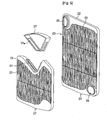
FIGS. 4 and5 , theheat exchanger 20 includes afirst heat exchanger 21 and asecond heat exchanger 22 larger than thefirst heat exchanger 21. The first, andsecond heat exchangers tubes 23 of the first and second heat exchangers are arranged at regular intervals, and is constructed such that the air can flow freely between thetubes 23. - In a top of the
first heat exchanger 21, there is aninduction hole 24 for introducing the air guided through the regeneratingcover 57 into thefirst heat exchanger 21. In one side of the lower side of each of the first, andsecond heat exchangers hole 26 for making the first, andsecond heat exchangers - In one side of a top side of the
second heat exchanger 22, there is adischarge hole 25 for discharging air from thesecond heat exchanger 22. - At a bottom of each of the first, and
second heat exchangers drain hole 27 for draining condensed water from theheat exchanger 20. - It is preferable that the regenerating
cover 57 has a size and a shape matched to the regeneratingflow passage 38. In a lower side of the regeneratingcover 57, there is aguide hole 57a formed in conformity with, and in communication with, theinduction hole 24. - Therefore, the air blowing through the regenerating
flow passage 38 is introduced into thefirst heat exchanger 21 through theguide hole 57a in the regeneratingcover 57, and theinduction hole 24 in thefirst heat exchanger 21, and therefrom into thesecond heat exchanger 22 through the connectingholes 26, flows through thesecond heat exchanger 32, and discharged to the circulatingduct 39 through thedischarge hole 25. - The operation of the dehumidifier of the present invention will be described in detail with reference to
FIG. 6 . - As indicated with large arrows, when humid room air is drawn into the
case 10 through theinlets fan 41, the air has foreign matters removed therefrom as the air passes through thefilter 80, and passes through thedesiccant assembly 30 through theheat exchanger 20. - In this instance, the air has moisture removed therefrom as the air passes through the pass through holes in the
desiccant member 32, and is discharged to the room through theoutlet 13 by the rotating power of thefan 41 as the air passes through theblower assembly 40. - Next, as indicated with small arrows, in a regenerating process for drying the
desiccant member 32 of thedesiccant assembly 30 continuously, the air blown forcibly by the rotation of the regeneratingfan 52 passes through theheater 60 through theheater case 55, and is heated to warm air such that the warm air evaporates moisture absorbed in thedesiccant member 32. - The high temperature, humid air passed through the
desiccant member 32 moves toward theheat exchanger 20 through the regeneratingflow passage 38, and introduced into the regeneratingcover 57. Then, the high temperature, humid air circulates through an inside of theheat exchanger 20, and has moisture therein condensed as the high temperature, humid air heat exchanges with the room air having a relatively low temperature drawn through theinlets drain groove 61 through thedrain hole 27 at the bottom of each of the heat exchangers. - The water condensed at the
heat exchanger 20 thus is guided to thedrain pan 60, and held in thewater tank 71, and the air passed through theheat exchanger 20 repeats circulation in which the air is guided to the regeneratingflow passage 38 through therotor housing 35 and the circulatingduct 39 again by the regeneratingfan 52, to repeat the regenerating process of drying thedesiccant member 32, continuously. - Thus, the dehumidifier of the present invention removes moisture from the room air by means of two streams of air flow. That is, the room air drawn by the
fan 41 passes through, and has moisture therein absorbed at, thedesiccant member 32, and is discharged to an outside of the dehumidifier through theoutlet 13. - At the same time with this, while the dehumidifier makes the high temperature air to flow through the
regenerative flow passage 38 by the regeneratingfan 52, the dehumidifier separates the moisture from a portion of the desiccant member again and blows toward theheat exchanger 20, to condense, and remove the moisture from the air, at theheat exchanger 20, and circulates the air by the regeneratingfan 52. - In the meantime,
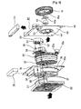
FIGS. 7 and8 each illustrates another embodiment of the dehumidifier, of which basic system is identical to the foregoing dehumidifier, except that the another embodiment is different form the foregoing embodiment in that the dehumidifier of the another embodiment includesinlets front frame 111 and therear frame 112 of thecase 110 for drawing air, together withfilters 180, and awater tank opening 111b in the front of thefront frame 111. - Therefore, the dehumidifier of another embodiment draws through the opposite sides of the
case 110 by thefan 41. Moreover, when thewater tank 71 is taken out of the dehumidifier after the dehumidification is finished, the user opens thefront panel 116, and pulls out thewater tank 71 from thecase 110. - Since the dehumidifier of another embodiment has the
inlets front panel 116 for pass through of the air. - Next, a dehumidifier in accordance with another preferred embodiment of the present invention will be described with reference to
FIGS. 9 to 13 . - The dehumidifier of the embodiment includes a
case 210, aheat exchanger 20, adesiccant assembly 50, ablower assembly 40, and aregenerator assembly 50. Theheat exchanger 20, thedesiccant assembly 50, theblower assembly 40, and theregenerator assembly 50 are identical to the foregoing embodiment, of which detailed description will be omitted. - The
case 210 is substantially hexahedral, and has individual sides. That is, thecase 210 has afront frame 211 of a front exterior thereof, arear frame 212 of a rear exterior thereof, twoside panels top panel 214 of a top exterior thereof, and abase pan 270 at a bottom thereof, which are formed individually. - That is, the
case 210 is formed as thefront frame 211 and therear frame 212 are mounted at a front and a rear of thebase pan 270, and theside panels base pan 270, and thetop panel 214 is mounted to a top. - The
front frame 211, therear frame 212, and theside frames inlets - In more detail, the gaps between a left edge and a right edge of each of the
front frame 211 and the rear frame 120 and a front edge and a rear edge of each of theside panels inlets - Insides of the
side panels inlets filters 280 for cleaning room air. Thefilter 280 is placed in and pulled out of thecase 210 through afilter insertion slot 211b extended in an up/down direction in thefront frame 211. - The
filter 280, for filtering foreign matters from air, may include a single unit selected from a prefilter for filtering relatively large sized dust from the air drawn through theinlets - At a
side panel 213b opposite to theside panel 213a having theinlets amount indicating portion 213c is formed for indicating a water holding amount of thewater tank 271 to be described later. The water holdingamount indicating portion 213c extends in an up/down direction at middle of theside panel 213b, and is transparent so that the water holding amount of thewater tank 271 can be visible from an outside of the dehumidifier. - In front of the
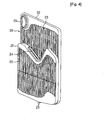
front frame 211, there is afront panel 216 for making a front exterior beautiful. Thefront panel 216 has a size and a shape corresponding to thefront frame 211, and is coupled to thefront frame 211 at a side edge thereof with hinges for rotation in a lateral direction. - The
front panel 216 has afastening member 216a at a side edge for fastening/unfastening thefront panel 216 to/from thefront frame 211. Thefastening member 216a may be a hook or a magnet. - Referring to
FIG. 13 , on the front of thefront panel 216, there may be various patterns or photographs attached thereto for decorating the exterior beautiful. - Accordingly, by making the
front panel 216 to be rotatable in the lateral direction, thefront panel 216, not only enables easy replacement of thefilter 280, but also makes the front exterior of the dehumidifier beautiful. - The
top panel 214 is rectangular substantially, and has one side provided with adisplay unit 215 for displaying an operation state of the dehumidifier, and the other side provided with awater tank opening 214c. - Though not shown, on one side of the
display unit 215, there is a plurality of operation buttons for operating the dehumidifier, and a watertank opening cover 214d for closing thewater tank opening 214c. - In the middle of the top panel between the
display unit 215 and thewater tank opening 214c, there is anoutlet 214a for discharging dehumidifier air. Alike the foregoing embodiment, theoutlet 214a is opened/closed by adischarge louver 214b. Thedischarge louver 214b may open/close theoutlet 214 as thedischarge louver 214b is moved by a driving unit such as a step motor, or different from this, by sliding. - In the meantime, on one side of an inside of the
case 210, i.e., at an inside of theside panel 213b opposite to the side panel having theinlets water tank 271 for holding condensed water from theheat exchanger 20. Thewater tank 271 can be drawn upward through thewater tank opening 214c in thetop panel 24. preferably, on top of thewater tank 271, there is ahandle 271a for the user to hold thewater tank 271 with a hand and draw thewater tank 271 easily. - The
base pan 270 is a box having all sides enclosed except a top side for collecting the water held in thewater tank 271. In order to pump up the water held in thebase pan 270 to thewater tank 271, a pump P is mounted on thebase pan 270, and a hose H is connected to the pump P and thewater tank 271 for guiding the pumped water to thewater tank 271. Of course, different from this, the hose H and the pump P may be connected to theheat exchanger 20 and thewater tank 271 directly, for pumping the condensed water from theheat exchanger 20 to thewater tank 271 directly without passing through thebase pan 270. - The operation of the dehumidifier will be described.
- Upon putting the dehumidifier into operation by operating operation buttons (not shown) on the
top panel 214, thefan 41 rotates to draw room air through theinlets side panel 213a. The air has moisture therein removed therefrom as the air passes through thedesiccant member 32 via theheat exchanger 20, and is discharged upward through thedischarge louver 214b in theoutlet 214a. - In this instance, as the air circulates through the
regenerative flow passage 38, theheat exchanger 20, and the circulatingduct 39 by theregenerator assembly 50, a portion of moisture is removed from thedesiccant member 32. - During this regenerating process, the condensed water from the
heat exchanger 20 is collected in thebase pan 270 guided by thedrain pan 60. Then, the water is guided to thewater tank 271 along the hose H by the pump P, and held therein. - The user looks at the water holding
amount indicating portion 213c on theside panel 213b from an outside of the dehumidifier with naked eyes, to notice an amount of water held in thewater tank 271. - When the user intends to empty the
water tank 271, the user rotates the watertank opening cover 214d, to open thewater tank opening 214c, holds thehandle 271a on thewater tank 271, and pulls thewater tank 271 upward, and empties thewater tank 271. -
FIGS. 12 to 15 illustrate a variation of the embodiment of the dehumidifier inFIG. 9 . The dehumidifier in accordance with the embodiment has one 213a ofside panels inlets - For this, the side panel 130 has a
driving unit 300 mounted on each of opposite edges of the side panel 130 for moving theside panel 213a. The drivingunit 300 includes apanel driving motor 301 fixedly secured to the side panel 130, and apinion gear 302 connected to one end of arotating shaft 303 of thepanel driving motor 301. - At inside edges of the
front frame 211 and therear frame 212, there are rack gears 305 extended in a lateral direction for engagement with the pinion gears respectively. - Therefore, when the
pinion gear 302 is rotated by thepanel driving motor 301, thepinion gear 302 is moved along therack gear 305. According to this, theside panel 213a moves in a lateral direction. - There are
guide bars 311 extended to an inner side of thecase 210 from respective corners of theside panel 213a for guiding movement of theside panel 213a. There areguide grooves 312 in an upper side and a lower side of each of thefront frame 211 and therear frame 212 for placing and guiding the guide bars 311. - Therefore, when the
side panel 213a moves in a lateral direction to an inside or an outside of thecase 210 by actions of the drivingunits 300 and the rack gears 305, the guide bars 311 move along theguide grooves 312, enabling theside panel 213a to move smoothly along an exact path. - The dehumidifier of the embodiment opens/closes the
inlets side panel 213a in the lateral direction. - That is, referring to
FIG. 14A , when the dehumidifier is put into operation, the pinion gears 302 of the drivingunits 300 rotate in one direction, to move theside panel 213a toward an outer side of thecase 210 in a lateral direction, to open theinlets front frame 211 and therear frame 212, and theside panel 213a, accordingly. - Opposite to this, referring to
FIG. 14B , when operation of the dehumidifier is stopped, the pinion gears 302 of the drivingunits 300 rotate in a direction opposite to above, to move theside panel 213 toward an inner side of thecase 210 in a lateral direction, to close theinlets - On the other hand, though the embodiment has been described with reference to a dehumidifier having the driving units mounted on the
side panel 213a and the rack gears 305 mounted on thefront frame 211 and therear frame 212, opposite to this, the driving units may be mounted on thefront frame 211 and/or therear frame 212, and the rack gears may be mounted on theside panel 213a. - Of course, the side panel may be moved in the lateral direction by using known driving devices other than the foregoing rack and pinion.
- Or, different from the embodiment, the
side panel 213a may be moved, not in the lateral direction, but up/down direction, or as shown inFIG. 16 , may be rotated in the lateral direction, to form a gap for air flow between thefront frame 211 or therear frame 212 and theside panel 213a. - It will be apparent to those skilled in the art that various modifications and variations can be made in the present invention without departing from the spirit or scope of the inventions. Thus, it is intended that the present invention covers the modifications and variations of this invention provided they come within the scope of the appended claims.
Claims (14)
- A dehumidifier comprising:a case (10);inlets (11a, 12a) passed through the case for introduction of air from an outside of the case to an inside of the case;an outlet (14) formed to pass through a top of the case for discharging air dehumidified in the case to the outside of the case;a desiccant assembly (30) for absorbing moisture from air drawn into the case;a blower assembly (40) for drawing air through the inlets and blowing the air to the outlet;a regenerator assembly (50) for blowing hot air to the desiccant assembly for drying the desiccant assembly;a heat exchanger (20) arranged to receive the air blown by the regenerator assembly through the desiccant assembly and the air introduced through the inlets, and the heat exchanger further being arranged to separate the moisture from the air by condensing; anda water collecting assembly for collecting water condensed and separated from the air at the heat exchanger,wherein the air blown from the regenerator assembly comprises a portion of the air introduced through the inlets, and wherein the air blown from the regenerator assembly is kept circulating as the air flows to the regenerator assembly again through a portion of the desiccant assembly and the heat exchanger, andwherein the regenerator assembly further includes:a regenerating fan (52) for blowing air toward the desiccant assembly;a heater (56) for heating the air blown by the regenerating fan, the heater being provided in the rear of the desiccant assembly;a regenerating fan housing (54) housing the regenerating fan and arranged to guide the air from the regenerating fan to the heater; anda heater case (55) encasing the heater, having one side in communication with the regenerating fan housing, and the other side in communication with a portion of the desiccant assembly for guiding air from the regenerating fan to the desiccant assembly.
- The dehumidifier as claimed in claim 1, wherein the inlets (11 a, 12a) are formed at least two places.
- The dehumidifier as claimed in claim 1, wherein the desiccant assembly includes:a desiccant member (32) for absorbing moisture from air;a desiccant rotor (33) rotatably mounted for housing the desiccant member;a desiccant rotor housing (35) for rotatably supporting the desiccant rotor; anda rotating unit for rotating the desiccant rotor.
- The dehumidifier as claimed in claim 1, wherein the blower assembly (40) includes:a fan (41) for generating a suction power for drawing air;a blower housing (43) for housing and supporting the fan; anda fan motor (42) mounted on the blower housing for rotating the fan.
- The dehumidifier as claimed in claim 1, wherein the regenerator assembly includes:a regenerating motor (53) for providing a rotating power to rotate the regenerating fan.
- The dehumidifier as claimed in claim 1, wherein the heat exchanger includes:a plurality of tubes (23) arranged at predetermined intervals;an inlet (24) for introduction of air flowing through the desiccant assembly;an outlet (25) for discharging the air heat exchanged as the air flows through the tubes; anddrain holes (27) for draining condensed water from the tubes.
- The dehumidifier as claimed in claim 1, wherein the water collecting assembly includes:a drain pan (60) under the heat exchanger for guiding water dropped from the heat exchanger to a lower side; anda water tank (71) mounted in the case under the drain pan so as to be movable to an inside/outside of the case for holding the water guided from the drain pan.
- The dehumidifier as claimed in claim 1, wherein the water collecting assembly includes:a drain pan (60) under the heat exchanger for guiding water dropped from the heat exchanger to a lower side;a base pan (70) fixedly mounted under the drain pan for holding the water guided from the drain pan temporarily;a water tank (71) mounted to be movable to an inside/outside of the case for holding the water from the base pan; anda pump for pumping up the water from the base pan to the water tank.
- The dehumidifier as claimed in claim 1, further comprising a discharge louver movably mounted at the discharge opening for opening/closing the outlet.
- The dehumidifier as claimed in claim 1, wherein the case includes:a front frame of a box shape with an opened rear side;a rear frame of a box shape with an opened front for coupling to a rear of the front frame.
- The dehumidifier as claimed in claim 1, wherein the case includes:a base pan of a bottom thereof;a front frame coupled to a front of the base pan;a rear frame coupled to a rear of the base pan;two side panels coupled to opposite edges of the front frame and the rear frame; anda top panel of a top thereof coupled to top sides of the front frame and the rear frame.
- The dehumidifier as claimed in claim 1, wherein the case includes:a base pan of a bottom thereof;a front frame (11) coupled to a front of the base pan;a rear frame (12) coupled to a rear of the base pan;a top panel of a top thereof coupled to top sides of the front frame and the rear frame;a first side panel fixedly secured to one side edge of each of the front frame and the rear frame; anda second side panel mounted to the other side edge of each of the front frame and the rear frame so as to be movable in a lateral direction to open/close inlets formed between the second side panel and the front frame and the rear frame depending on a direction of movement of the second side panel.
- The dehumidifier as claimed in claim 1, further comprising a front panel mounted to a front of the case.
- The dehumidifier as claimed in claim 5, wherein the heater is provided between the regenerating fan and the desiccant assembly.
Applications Claiming Priority (4)
| Application Number | Priority Date | Filing Date | Title |
|---|---|---|---|
| KR1020050051318A KR20060131112A (en) | 2005-06-15 | 2005-06-15 | A dehumidifier |
| KR1020050051320A KR101158581B1 (en) | 2005-06-15 | 2005-06-15 | A dehumidifier |
| KR1020050052921A KR20060133206A (en) | 2005-06-20 | 2005-06-20 | A dehumidifier |
| PCT/KR2006/002231 WO2006135171A2 (en) | 2005-06-15 | 2006-06-12 | Dehumidifier |
Publications (3)
| Publication Number | Publication Date |
|---|---|
| EP1899657A2 EP1899657A2 (en) | 2008-03-19 |
| EP1899657A4 EP1899657A4 (en) | 2012-04-25 |
| EP1899657B1 true EP1899657B1 (en) | 2014-03-05 |
Family
ID=37532710
Family Applications (1)
| Application Number | Title | Priority Date | Filing Date |
|---|---|---|---|
| EP06768829.1A Not-in-force EP1899657B1 (en) | 2005-06-15 | 2006-06-12 | Dehumidifier |
Country Status (3)
| Country | Link |
|---|---|
| US (1) | US7856840B2 (en) |
| EP (1) | EP1899657B1 (en) |
| WO (1) | WO2006135171A2 (en) |
Families Citing this family (29)
| Publication number | Priority date | Publication date | Assignee | Title |
|---|---|---|---|---|
| KR101231321B1 (en) * | 2006-04-27 | 2013-02-07 | 엘지전자 주식회사 | A dehumidifier |
| KR20070107281A (en) * | 2006-05-02 | 2007-11-07 | 엘지전자 주식회사 | A dehumidifier |
| KR101476297B1 (en) * | 2008-08-27 | 2014-12-24 | 엘지전자 주식회사 | Dehumidifier |
| KR101534292B1 (en) * | 2008-08-27 | 2015-07-03 | 엘지전자 주식회사 | Dehumidifier |
| KR101534170B1 (en) * | 2008-08-27 | 2015-07-06 | 엘지전자 주식회사 | Dehumidifier |
| KR101173343B1 (en) * | 2008-10-22 | 2012-08-10 | 웅진코웨이주식회사 | Air cleaner having dehumidification function |
| GB2482100B (en) | 2009-04-27 | 2014-01-22 | Dri Eaz Products Inc | Systems and methods for operating and monitoring dehumidifiers |
| US20110061408A1 (en) * | 2009-09-11 | 2011-03-17 | Tom Schnelle | Dehumidifiers for high temperature operation, and associated systems and methods |
| US8641809B2 (en) * | 2010-10-26 | 2014-02-04 | Munters Corporation | Rotor support system |
| JP5799201B2 (en) * | 2011-03-16 | 2015-10-21 | パナソニックIpマネジメント株式会社 | Dehumidifier |
| CA2847163C (en) * | 2011-08-31 | 2019-12-03 | Dri-Eaz Products, Inc. | Dehumidifiers with improved fluid management and associated methods of use and manufature |
| CN102383822B (en) * | 2011-09-09 | 2013-06-26 | 中国船舶重工集团公司第七一八研究所 | Air purification, cooling and dehumidification integrated device for mine |
| DE112012004290T5 (en) | 2011-10-14 | 2014-07-31 | Dri-Eaz Products, Inc. | Dehumidifiers with improved heat exchanger blocks and associated methods of use and manufacture |
| USD731632S1 (en) | 2012-12-04 | 2015-06-09 | Dri-Eaz Products, Inc. | Compact dehumidifier |
| US8956447B2 (en) * | 2013-01-11 | 2015-02-17 | Norm Pacific Automation Corp. | Desiccant wheel dehumidifier and heat exchanger thereof |
| KR20150081595A (en) * | 2014-01-06 | 2015-07-15 | 삼성전자주식회사 | Dehumidifier |
| USD802725S1 (en) | 2014-02-14 | 2017-11-14 | Access Business Group International Llc | Air treatment system |
| US9821260B2 (en) | 2014-02-14 | 2017-11-21 | Access Business Group International Llc | Air treatment system |
| USD846105S1 (en) | 2014-02-14 | 2019-04-16 | Access Business Group International Llc | Air treatment system |
| CN104949214B (en) * | 2014-03-31 | 2018-01-05 | Lg电子株式会社 | Dehumidifier |
| CN104949215B (en) * | 2014-03-31 | 2018-04-06 | Lg电子株式会社 | Dehumidifier |
| CN104259161A (en) * | 2014-09-16 | 2015-01-07 | 芜湖市华益阀门制造有限公司 | Air drying device for inner surface cleaning machine |
| USD825046S1 (en) | 2017-01-09 | 2018-08-07 | Access Business Group International Llc | Air treatment system |
| KR102069074B1 (en) | 2018-08-23 | 2020-01-22 | 엘지전자 주식회사 | Dehumidifier |
| KR102556967B1 (en) * | 2018-08-23 | 2023-07-18 | 엘지전자 주식회사 | Dehumidifier |
| DE102019210222B4 (en) * | 2019-07-10 | 2021-02-11 | Dometic Sweden Ab | Compressor cooling unit for a refrigerator or a cooler |
| CN111964167B (en) * | 2020-08-10 | 2022-04-22 | 广东英为拓科技有限公司 | Rotary dehumidifier convenient to rotary mechanism drainage |
| CN115188299B (en) * | 2022-06-22 | 2023-11-14 | 义乌市恒风传媒科技有限公司 | A bill-board for food propaganda |
| US11844470B1 (en) * | 2022-12-13 | 2023-12-19 | Wei Huang | Hand drying apparatus with moisture absorption arrangement |
Citations (2)
| Publication number | Priority date | Publication date | Assignee | Title |
|---|---|---|---|---|
| EP0693660A2 (en) * | 1994-07-22 | 1996-01-24 | Sanyo Electric Co. Ltd | Ventilator/dryer assembly |
| GB2333722A (en) * | 1998-01-26 | 1999-08-04 | Kankyo Co Ltd | Dehumidification of air |
Family Cites Families (13)
| Publication number | Priority date | Publication date | Assignee | Title |
|---|---|---|---|---|
| US3144901A (en) * | 1960-05-13 | 1964-08-18 | Lizenzia A G | Movable air conditioning apparatus |
| US3850007A (en) * | 1972-06-06 | 1974-11-26 | A Mcfarlan | Air conditioning system and method |
| DE4437494A1 (en) * | 1994-10-20 | 1996-04-25 | Graeff Roderich Wilhelm | Method and device for drying moist gas |
| US5478379A (en) * | 1994-10-27 | 1995-12-26 | Bevins; Rick C. | Air purification conversion cartridge for dehumidifier |
| US5732562A (en) * | 1996-08-13 | 1998-03-31 | Moratalla; Jose M. | Method and apparatus for regenerating desiccants in a closed cycle |
| US5761915A (en) * | 1997-03-12 | 1998-06-09 | Fedders Corporation | Method and apparatus for supplying conditioned fresh air to an indoor area |
| CN2300029Y (en) * | 1997-04-14 | 1998-12-09 | 刘宗源 | Energy-saving rotary wheel dehumidifier |
| US7043934B2 (en) * | 2000-05-01 | 2006-05-16 | University Of Maryland, College Park | Device for collecting water from air |
| CN2531298Y (en) | 2002-03-14 | 2003-01-15 | 伊莱电器(杭州)有限公司 | Air conditioner with water-free humidifying device |
| JP3445790B1 (en) * | 2002-05-10 | 2003-09-08 | 株式会社カンキョー | Dehumidifier |
| KR100504503B1 (en) * | 2003-01-14 | 2005-08-01 | 엘지전자 주식회사 | air conditioning system |
| JP2004316952A (en) | 2003-04-11 | 2004-11-11 | Toto Ltd | Remote control system for housing equipment apparatus |
| JP2005265256A (en) | 2004-03-17 | 2005-09-29 | Tiger Vacuum Bottle Co Ltd | Portable dehumidifier |
-
2006
- 2006-06-12 EP EP06768829.1A patent/EP1899657B1/en not_active Not-in-force
- 2006-06-12 US US11/450,306 patent/US7856840B2/en not_active Expired - Fee Related
- 2006-06-12 WO PCT/KR2006/002231 patent/WO2006135171A2/en active Application Filing
Patent Citations (2)
| Publication number | Priority date | Publication date | Assignee | Title |
|---|---|---|---|---|
| EP0693660A2 (en) * | 1994-07-22 | 1996-01-24 | Sanyo Electric Co. Ltd | Ventilator/dryer assembly |
| GB2333722A (en) * | 1998-01-26 | 1999-08-04 | Kankyo Co Ltd | Dehumidification of air |
Also Published As
| Publication number | Publication date |
|---|---|
| US20060283327A1 (en) | 2006-12-21 |
| EP1899657A4 (en) | 2012-04-25 |
| EP1899657A2 (en) | 2008-03-19 |
| US7856840B2 (en) | 2010-12-28 |
| WO2006135171A3 (en) | 2009-05-07 |
| WO2006135171A2 (en) | 2006-12-21 |
Similar Documents
| Publication | Publication Date | Title |
|---|---|---|
| EP1899657B1 (en) | Dehumidifier | |
| US20060278085A1 (en) | Dehumidifier | |
| US20070062370A1 (en) | Dehumidifier | |
| CN1880858B (en) | Dehumidifier | |
| CN1880859B (en) | Dehumidifier | |
| US20060278084A1 (en) | Dehumidifier | |
| CN1880864B (en) | Dehumidifier | |
| KR101440521B1 (en) | Dehumidifier | |
| CN1880865B (en) | Dehumidifier | |
| WO2007052947A2 (en) | Dehumidifier | |
| KR20100025346A (en) | Dehumidifier | |
| JP3857809B2 (en) | Dehumidifier | |
| KR101450556B1 (en) | Dehumidifing rotor and Dehumidifier having the same | |
| EP2116783A2 (en) | Dehumidifier having dehimidifying rotor | |
| KR101158581B1 (en) | A dehumidifier | |
| KR101403010B1 (en) | Apparatus for humidification and dehumidification | |
| KR101153691B1 (en) | A dehumidifier | |
| KR20060129672A (en) | A dehumidifier | |
| KR20100025347A (en) | Dehumidifier | |
| KR101158578B1 (en) | A dehumidifier | |
| KR101450555B1 (en) | Dehumidifier | |
| KR20060131113A (en) | A dehumidifier | |
| KR20060129673A (en) | A dehumidifier | |
| KR20060129675A (en) | A dehumidifier | |
| KR20060133206A (en) | A dehumidifier |
Legal Events
| Date | Code | Title | Description |
|---|---|---|---|
| PUAI | Public reference made under article 153(3) epc to a published international application that has entered the european phase |
Free format text: ORIGINAL CODE: 0009012 |
|
| 17P | Request for examination filed |
Effective date: 20071211 |
|
| AK | Designated contracting states |
Kind code of ref document: A2 Designated state(s): AT BE BG CH CY CZ DE DK EE ES FI FR GB GR HU IE IS IT LI LT LU LV MC NL PL PT RO SE SI SK TR |
|
| AX | Request for extension of the european patent |
Extension state: AL BA HR MK YU |
|
| RAX | Requested extension states of the european patent have changed |
Extension state: BA Extension state: RS Extension state: AL Extension state: HR Extension state: MK |
|
| DAX | Request for extension of the european patent (deleted) | ||
| R17D | Deferred search report published (corrected) |
Effective date: 20090507 |
|
| A4 | Supplementary search report drawn up and despatched |
Effective date: 20120328 |
|
| RIC1 | Information provided on ipc code assigned before grant |
Ipc: B01D 53/26 20060101ALI20120322BHEP Ipc: F24F 5/00 20060101ALI20120322BHEP Ipc: F24F 3/14 20060101AFI20120322BHEP |
|
| 17Q | First examination report despatched |
Effective date: 20121005 |
|
| GRAP | Despatch of communication of intention to grant a patent |
Free format text: ORIGINAL CODE: EPIDOSNIGR1 |
|
| INTG | Intention to grant announced |
Effective date: 20130924 |
|
| GRAS | Grant fee paid |
Free format text: ORIGINAL CODE: EPIDOSNIGR3 |
|
| GRAA | (expected) grant |
Free format text: ORIGINAL CODE: 0009210 |
|
| AK | Designated contracting states |
Kind code of ref document: B1 Designated state(s): AT BE BG CH CY CZ DE DK EE ES FI FR GB GR HU IE IS IT LI LT LU LV MC NL PL PT RO SE SI SK TR |
|
| REG | Reference to a national code |
Ref country code: GB Ref legal event code: FG4D |
|
| REG | Reference to a national code |
Ref country code: CH Ref legal event code: EP |
|
| REG | Reference to a national code |
Ref country code: AT Ref legal event code: REF Ref document number: 655153 Country of ref document: AT Kind code of ref document: T Effective date: 20140315 |
|
| REG | Reference to a national code |
Ref country code: IE Ref legal event code: FG4D |
|
| REG | Reference to a national code |
Ref country code: DE Ref legal event code: R096 Ref document number: 602006040511 Country of ref document: DE Effective date: 20140417 |
|
| REG | Reference to a national code |
Ref country code: AT Ref legal event code: MK05 Ref document number: 655153 Country of ref document: AT Kind code of ref document: T Effective date: 20140305 |
|
| REG | Reference to a national code |
Ref country code: NL Ref legal event code: VDEP Effective date: 20140305 |
|
| PG25 | Lapsed in a contracting state [announced via postgrant information from national office to epo] |
Ref country code: LT Free format text: LAPSE BECAUSE OF FAILURE TO SUBMIT A TRANSLATION OF THE DESCRIPTION OR TO PAY THE FEE WITHIN THE PRESCRIBED TIME-LIMIT Effective date: 20140305 |
|
| REG | Reference to a national code |
Ref country code: LT Ref legal event code: MG4D |
|
| PG25 | Lapsed in a contracting state [announced via postgrant information from national office to epo] |
Ref country code: SE Free format text: LAPSE BECAUSE OF FAILURE TO SUBMIT A TRANSLATION OF THE DESCRIPTION OR TO PAY THE FEE WITHIN THE PRESCRIBED TIME-LIMIT Effective date: 20140305 Ref country code: CY Free format text: LAPSE BECAUSE OF FAILURE TO SUBMIT A TRANSLATION OF THE DESCRIPTION OR TO PAY THE FEE WITHIN THE PRESCRIBED TIME-LIMIT Effective date: 20140305 Ref country code: FI Free format text: LAPSE BECAUSE OF FAILURE TO SUBMIT A TRANSLATION OF THE DESCRIPTION OR TO PAY THE FEE WITHIN THE PRESCRIBED TIME-LIMIT Effective date: 20140305 Ref country code: AT Free format text: LAPSE BECAUSE OF FAILURE TO SUBMIT A TRANSLATION OF THE DESCRIPTION OR TO PAY THE FEE WITHIN THE PRESCRIBED TIME-LIMIT Effective date: 20140305 |
|
| PG25 | Lapsed in a contracting state [announced via postgrant information from national office to epo] |
Ref country code: LV Free format text: LAPSE BECAUSE OF FAILURE TO SUBMIT A TRANSLATION OF THE DESCRIPTION OR TO PAY THE FEE WITHIN THE PRESCRIBED TIME-LIMIT Effective date: 20140305 |
|
| PG25 | Lapsed in a contracting state [announced via postgrant information from national office to epo] |
Ref country code: EE Free format text: LAPSE BECAUSE OF FAILURE TO SUBMIT A TRANSLATION OF THE DESCRIPTION OR TO PAY THE FEE WITHIN THE PRESCRIBED TIME-LIMIT Effective date: 20140305 Ref country code: BE Free format text: LAPSE BECAUSE OF FAILURE TO SUBMIT A TRANSLATION OF THE DESCRIPTION OR TO PAY THE FEE WITHIN THE PRESCRIBED TIME-LIMIT Effective date: 20140305 Ref country code: BG Free format text: LAPSE BECAUSE OF FAILURE TO SUBMIT A TRANSLATION OF THE DESCRIPTION OR TO PAY THE FEE WITHIN THE PRESCRIBED TIME-LIMIT Effective date: 20140605 Ref country code: NL Free format text: LAPSE BECAUSE OF FAILURE TO SUBMIT A TRANSLATION OF THE DESCRIPTION OR TO PAY THE FEE WITHIN THE PRESCRIBED TIME-LIMIT Effective date: 20140305 Ref country code: RO Free format text: LAPSE BECAUSE OF FAILURE TO SUBMIT A TRANSLATION OF THE DESCRIPTION OR TO PAY THE FEE WITHIN THE PRESCRIBED TIME-LIMIT Effective date: 20140305 Ref country code: IS Free format text: LAPSE BECAUSE OF FAILURE TO SUBMIT A TRANSLATION OF THE DESCRIPTION OR TO PAY THE FEE WITHIN THE PRESCRIBED TIME-LIMIT Effective date: 20140705 Ref country code: CZ Free format text: LAPSE BECAUSE OF FAILURE TO SUBMIT A TRANSLATION OF THE DESCRIPTION OR TO PAY THE FEE WITHIN THE PRESCRIBED TIME-LIMIT Effective date: 20140305 |
|
| PG25 | Lapsed in a contracting state [announced via postgrant information from national office to epo] |
Ref country code: ES Free format text: LAPSE BECAUSE OF FAILURE TO SUBMIT A TRANSLATION OF THE DESCRIPTION OR TO PAY THE FEE WITHIN THE PRESCRIBED TIME-LIMIT Effective date: 20140305 Ref country code: PL Free format text: LAPSE BECAUSE OF FAILURE TO SUBMIT A TRANSLATION OF THE DESCRIPTION OR TO PAY THE FEE WITHIN THE PRESCRIBED TIME-LIMIT Effective date: 20140305 Ref country code: SK Free format text: LAPSE BECAUSE OF FAILURE TO SUBMIT A TRANSLATION OF THE DESCRIPTION OR TO PAY THE FEE WITHIN THE PRESCRIBED TIME-LIMIT Effective date: 20140305 |
|
| REG | Reference to a national code |
Ref country code: DE Ref legal event code: R097 Ref document number: 602006040511 Country of ref document: DE |
|
| PG25 | Lapsed in a contracting state [announced via postgrant information from national office to epo] |
Ref country code: PT Free format text: LAPSE BECAUSE OF FAILURE TO SUBMIT A TRANSLATION OF THE DESCRIPTION OR TO PAY THE FEE WITHIN THE PRESCRIBED TIME-LIMIT Effective date: 20140707 |
|
| PLBE | No opposition filed within time limit |
Free format text: ORIGINAL CODE: 0009261 |
|
| STAA | Information on the status of an ep patent application or granted ep patent |
Free format text: STATUS: NO OPPOSITION FILED WITHIN TIME LIMIT |
|
| PG25 | Lapsed in a contracting state [announced via postgrant information from national office to epo] |
Ref country code: DK Free format text: LAPSE BECAUSE OF FAILURE TO SUBMIT A TRANSLATION OF THE DESCRIPTION OR TO PAY THE FEE WITHIN THE PRESCRIBED TIME-LIMIT Effective date: 20140305 Ref country code: LU Free format text: LAPSE BECAUSE OF FAILURE TO SUBMIT A TRANSLATION OF THE DESCRIPTION OR TO PAY THE FEE WITHIN THE PRESCRIBED TIME-LIMIT Effective date: 20140612 Ref country code: MC Free format text: LAPSE BECAUSE OF FAILURE TO SUBMIT A TRANSLATION OF THE DESCRIPTION OR TO PAY THE FEE WITHIN THE PRESCRIBED TIME-LIMIT Effective date: 20140305 |
|
| REG | Reference to a national code |
Ref country code: CH Ref legal event code: PL |
|
| 26N | No opposition filed |
Effective date: 20141208 |
|
| REG | Reference to a national code |
Ref country code: DE Ref legal event code: R097 Ref document number: 602006040511 Country of ref document: DE Effective date: 20141208 |
|
| REG | Reference to a national code |
Ref country code: IE Ref legal event code: MM4A |
|
| PG25 | Lapsed in a contracting state [announced via postgrant information from national office to epo] |
Ref country code: LI Free format text: LAPSE BECAUSE OF NON-PAYMENT OF DUE FEES Effective date: 20140630 Ref country code: CH Free format text: LAPSE BECAUSE OF NON-PAYMENT OF DUE FEES Effective date: 20140630 Ref country code: IE Free format text: LAPSE BECAUSE OF NON-PAYMENT OF DUE FEES Effective date: 20140612 |
|
| PG25 | Lapsed in a contracting state [announced via postgrant information from national office to epo] |
Ref country code: SI Free format text: LAPSE BECAUSE OF FAILURE TO SUBMIT A TRANSLATION OF THE DESCRIPTION OR TO PAY THE FEE WITHIN THE PRESCRIBED TIME-LIMIT Effective date: 20140305 |
|
| REG | Reference to a national code |
Ref country code: FR Ref legal event code: PLFP Year of fee payment: 11 |
|
| PG25 | Lapsed in a contracting state [announced via postgrant information from national office to epo] |
Ref country code: GR Free format text: LAPSE BECAUSE OF FAILURE TO SUBMIT A TRANSLATION OF THE DESCRIPTION OR TO PAY THE FEE WITHIN THE PRESCRIBED TIME-LIMIT Effective date: 20140606 |
|
| PG25 | Lapsed in a contracting state [announced via postgrant information from national office to epo] |
Ref country code: TR Free format text: LAPSE BECAUSE OF FAILURE TO SUBMIT A TRANSLATION OF THE DESCRIPTION OR TO PAY THE FEE WITHIN THE PRESCRIBED TIME-LIMIT Effective date: 20140305 Ref country code: HU Free format text: LAPSE BECAUSE OF FAILURE TO SUBMIT A TRANSLATION OF THE DESCRIPTION OR TO PAY THE FEE WITHIN THE PRESCRIBED TIME-LIMIT; INVALID AB INITIO Effective date: 20060612 |
|
| REG | Reference to a national code |
Ref country code: FR Ref legal event code: PLFP Year of fee payment: 12 |
|
| REG | Reference to a national code |
Ref country code: FR Ref legal event code: PLFP Year of fee payment: 13 |
|
| PGFP | Annual fee paid to national office [announced via postgrant information from national office to epo] |
Ref country code: IT Payment date: 20190614 Year of fee payment: 14 Ref country code: DE Payment date: 20190503 Year of fee payment: 14 |
|
| PGFP | Annual fee paid to national office [announced via postgrant information from national office to epo] |
Ref country code: FR Payment date: 20190508 Year of fee payment: 14 |
|
| PGFP | Annual fee paid to national office [announced via postgrant information from national office to epo] |
Ref country code: GB Payment date: 20190503 Year of fee payment: 14 |
|
| REG | Reference to a national code |
Ref country code: DE Ref legal event code: R119 Ref document number: 602006040511 Country of ref document: DE |
|
| GBPC | Gb: european patent ceased through non-payment of renewal fee |
Effective date: 20200612 |
|
| PG25 | Lapsed in a contracting state [announced via postgrant information from national office to epo] |
Ref country code: FR Free format text: LAPSE BECAUSE OF NON-PAYMENT OF DUE FEES Effective date: 20200630 Ref country code: GB Free format text: LAPSE BECAUSE OF NON-PAYMENT OF DUE FEES Effective date: 20200612 |
|
| PG25 | Lapsed in a contracting state [announced via postgrant information from national office to epo] |
Ref country code: DE Free format text: LAPSE BECAUSE OF NON-PAYMENT OF DUE FEES Effective date: 20210101 |
|
| PG25 | Lapsed in a contracting state [announced via postgrant information from national office to epo] |
Ref country code: IT Free format text: LAPSE BECAUSE OF NON-PAYMENT OF DUE FEES Effective date: 20200612 |