EP1898403B1 - Hologram information reproducing device - Google Patents
Hologram information reproducing device Download PDFInfo
- Publication number
- EP1898403B1 EP1898403B1 EP06747100A EP06747100A EP1898403B1 EP 1898403 B1 EP1898403 B1 EP 1898403B1 EP 06747100 A EP06747100 A EP 06747100A EP 06747100 A EP06747100 A EP 06747100A EP 1898403 B1 EP1898403 B1 EP 1898403B1
- Authority
- EP
- European Patent Office
- Prior art keywords
- light
- lens
- light source
- recording medium
- orientation
- Prior art date
- Legal status (The legal status is an assumption and is not a legal conclusion. Google has not performed a legal analysis and makes no representation as to the accuracy of the status listed.)
- Ceased
Links
- 230000003287 optical effect Effects 0.000 claims description 12
- 238000012545 processing Methods 0.000 description 14
- 239000000758 substrate Substances 0.000 description 8
- 230000008602 contraction Effects 0.000 description 2
- 238000012937 correction Methods 0.000 description 2
- 230000001678 irradiating effect Effects 0.000 description 2
- 238000012986 modification Methods 0.000 description 2
- 230000004048 modification Effects 0.000 description 2
- -1 acryl Chemical group 0.000 description 1
- 230000001427 coherent effect Effects 0.000 description 1
- 238000011161 development Methods 0.000 description 1
- 238000010586 diagram Methods 0.000 description 1
- 239000011521 glass Substances 0.000 description 1
- 238000000034 method Methods 0.000 description 1
- 229920000515 polycarbonate Polymers 0.000 description 1
- 239000004417 polycarbonate Substances 0.000 description 1
- 239000012260 resinous material Substances 0.000 description 1
Images

Classifications
-
- G—PHYSICS
- G11—INFORMATION STORAGE
- G11B—INFORMATION STORAGE BASED ON RELATIVE MOVEMENT BETWEEN RECORD CARRIER AND TRANSDUCER
- G11B7/00—Recording or reproducing by optical means, e.g. recording using a thermal beam of optical radiation by modifying optical properties or the physical structure, reproducing using an optical beam at lower power by sensing optical properties; Record carriers therefor
- G11B7/004—Recording, reproducing or erasing methods; Read, write or erase circuits therefor
- G11B7/0065—Recording, reproducing or erasing by using optical interference patterns, e.g. holograms
-
- G—PHYSICS
- G11—INFORMATION STORAGE
- G11B—INFORMATION STORAGE BASED ON RELATIVE MOVEMENT BETWEEN RECORD CARRIER AND TRANSDUCER
- G11B7/00—Recording or reproducing by optical means, e.g. recording using a thermal beam of optical radiation by modifying optical properties or the physical structure, reproducing using an optical beam at lower power by sensing optical properties; Record carriers therefor
- G11B7/08—Disposition or mounting of heads or light sources relatively to record carriers
- G11B7/083—Disposition or mounting of heads or light sources relatively to record carriers relative to record carriers storing information in the form of optical interference patterns, e.g. holograms
-
- G—PHYSICS
- G11—INFORMATION STORAGE
- G11B—INFORMATION STORAGE BASED ON RELATIVE MOVEMENT BETWEEN RECORD CARRIER AND TRANSDUCER
- G11B7/00—Recording or reproducing by optical means, e.g. recording using a thermal beam of optical radiation by modifying optical properties or the physical structure, reproducing using an optical beam at lower power by sensing optical properties; Record carriers therefor
- G11B7/08—Disposition or mounting of heads or light sources relatively to record carriers
- G11B7/09—Disposition or mounting of heads or light sources relatively to record carriers with provision for moving the light beam or focus plane for the purpose of maintaining alignment of the light beam relative to the record carrier during transducing operation, e.g. to compensate for surface irregularities of the latter or for track following
- G11B7/095—Disposition or mounting of heads or light sources relatively to record carriers with provision for moving the light beam or focus plane for the purpose of maintaining alignment of the light beam relative to the record carrier during transducing operation, e.g. to compensate for surface irregularities of the latter or for track following specially adapted for discs, e.g. for compensation of eccentricity or wobble
- G11B7/0956—Disposition or mounting of heads or light sources relatively to record carriers with provision for moving the light beam or focus plane for the purpose of maintaining alignment of the light beam relative to the record carrier during transducing operation, e.g. to compensate for surface irregularities of the latter or for track following specially adapted for discs, e.g. for compensation of eccentricity or wobble to compensate for tilt, skew, warp or inclination of the disc, i.e. maintain the optical axis at right angles to the disc
-
- G—PHYSICS
- G11—INFORMATION STORAGE
- G11B—INFORMATION STORAGE BASED ON RELATIVE MOVEMENT BETWEEN RECORD CARRIER AND TRANSDUCER
- G11B7/00—Recording or reproducing by optical means, e.g. recording using a thermal beam of optical radiation by modifying optical properties or the physical structure, reproducing using an optical beam at lower power by sensing optical properties; Record carriers therefor
- G11B7/24—Record carriers characterised by shape, structure or physical properties, or by the selection of the material
- G11B7/2403—Layers; Shape, structure or physical properties thereof
- G11B7/24035—Recording layers
- G11B7/24044—Recording layers for storing optical interference patterns, e.g. holograms; for storing data in three dimensions, e.g. volume storage
-
- G—PHYSICS
- G11—INFORMATION STORAGE
- G11B—INFORMATION STORAGE BASED ON RELATIVE MOVEMENT BETWEEN RECORD CARRIER AND TRANSDUCER
- G11B7/00—Recording or reproducing by optical means, e.g. recording using a thermal beam of optical radiation by modifying optical properties or the physical structure, reproducing using an optical beam at lower power by sensing optical properties; Record carriers therefor
- G11B7/08—Disposition or mounting of heads or light sources relatively to record carriers
- G11B7/09—Disposition or mounting of heads or light sources relatively to record carriers with provision for moving the light beam or focus plane for the purpose of maintaining alignment of the light beam relative to the record carrier during transducing operation, e.g. to compensate for surface irregularities of the latter or for track following
- G11B7/0925—Electromechanical actuators for lens positioning
Definitions
- the present invention relates to a device that reproduces information recorded on a hologram recording medium.
- optical recording media such as a CD (compact disk) and a DVD (digital versatile disk).
- a CD compact disk
- DVD digital versatile disk
- a sufficiently high density cannot be achieved for recording such a large amount of data, as a result of which a large amount of data cannot be recorded on one disk. Therefore, for recording such a large amount of data, recording must be performed while replacing a plurality of disks.
- a hologram recording medium on which a very large amount of data can be recorded compared to, for example, currently used CDs and DVDs is drawing attention.
- Hologram information recording is a method in which a light beam is separated into two coherent light beams, data modulation is performed on one of the light beams by a spatial light modulator to form a signal light, and the other light beam is combined as reference light at a recording medium, so that data is recorded as an interference pattern. Then, by irradiating the recording medium with reference light that is the same as that used during the recording, the signal light can be detected as reproduction light, so that the data can be reproduced.
- this hologram information recording/reproducing operation when the light wavelength and irradiation angle during the reproduction of the information are different from the light wavelength and irradiation angle during the recording of the information, the signal light is not reproduced. By making use of this characteristic, the light wavelength and the irradiation angle during the recording/reproduction of the information are changed to perform multiplexing of data on the same area of the recording medium, as a result of which the data is recorded.
- Patent Document 1 Japanese Unexamined Patent Application Publication No. 2002-216359
- the wavelength or the irradiation angle needs to be controlled with high precision.
- the irradiation angle is changed using a large, expensive galvanometer mirror. Therefore, a device becomes large and expensive.
- a hologram information reproducing device which can reproduce information from a recording medium on which hologram information is recorded, and which can be downsized.
- a hologram information reproducing device as defined in claim 1.
- the driving means can drive the orientation of the lens independently in the multiplex direction and the arrangement direction, so the driving means can drive the lens in the multiplex direction and the arrangement direction. Therefore, in reproducing hologram information, even if the light source unit is switched, the information can be precisely reproduced, and the hologram information on which angle multiplexing is performed can be precisely reproduced.
- the optical system comprises a cylinder in which the light source unit and the lens that transmits the reference light emitted from the light source are integrated and that the driving means are adapted to drive the orientation of the cylinder.
- the driving means can drive the orientation of the cylinder, in which the lens and the light source unit are integrated, independently in the multiplex direction and the arrangement direction, so that the driving means can drive the lens in the multiplex direction and the arrangement direction. Therefore, in reproducing hologram information, even if the light source unit is switched, the information can be precisely reproduced, and the hologram information on which angle multiplexing is performed can be precisely reproduced.
- the driving means change the orientation of the lens in the first direction and the second direction.
- the driving means can drive the orientation of the lens independently in the first and second directions. Therefore, the driving means can drive the lens in the first and second directions. Therefore, in reproducing hologram information, even if the light source unit is switched, the information can be precisely reproduced, and the hologram information on which angle multiplexing is performed can be precisely reproduced.
- the driving means drive the lens or the cylinder by a magnetic circuit.
- the recording medium have reflecting means that reflects the reproduction light, obtained by diffracting the reference light, towards the detecting means.
- the optical system that irradiates with reference light the recording medium on which information is recorded comprises a lens that transmits the reference light emitted from the light source unit, a mirror that directs the light transmitted through the lens towards the recording medium, and driving means that changes the orientation of the lens. Therefore, the driving means can drive the orientation of the lens or the orientation of a cylinder, in which the lens and the light source unit are integrated, independently in the multiplex direction and the arrangement direction. Consequently, the driving means can drive the lens in the multiplex direction and the arrangement direction.
- the driving means can drive the lens in the multiplex direction and the arrangement direction.
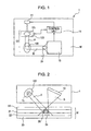
- Fig. 1 is a top view of a schematic structure of a hologram information reproducing device according to a first embodiment of the present invention.
- Fig. 2 is a side view of the hologram information reproducing device shown in Fig. 1 .
- a hologram information reproducing device 1 shown in Fig. 1 primarily comprises a light source unit 11 that emits reference light, an optical system 12 that irradiates with the reference light a recording medium M on which information is recorded, a photodetector 13 (serving as detecting means) that detects reproduction light obtained as a result of diffraction of the reference light at the recording medium M, and a control unit 14 that performs, for example, switching of the light source unit 11, driving of a lens, and processing of a reproduction signal obtained from the reproduction light.
- the optical system 12 is disposed on the same side as the light source unit 11 with respect to the recording medium M.
- the light source unit 11 comprises a light-source array in which a plurality of light sources (here, three light sources), having different wavelength ranges, are arranged in parallel.
- the number of light sources is not limited to three, so that it may be two, or four or more.
- the optical system 12 comprises a lens 121 that transmits reference light A from the light source unit 11, a mirror 122 that-directs towards the recording medium M the reference light A transmitted through the lens 121, and a lens actuator 123 (serving as first driving means) that changes the orientation of the lens 121.
- the recording medium M comprises, for example, a recording layer 21 on which an interference fringe is recorded, a transparent substrate 22 that clamps the recording medium 21, and a reflecting layer 23 (serving as reflecting means) that reflects reproduction light B, obtained by diffracting the reference light A, towards the photodetector 13.
- the reflecting layer 23 is provided at the lowest layer of the recording medium M.
- the recording layer 21 is formed of, for example, a resinous material, such as photopolymer
- the transparent substrate 22 is formed of, for example, polycarbonate, acryl, or glass.
- the recording medium M when the expansion coefficient of the recording layer 21 is larger than the expansion coefficient of the transparent substrate 22, the recording layer 21 expands considerably perpendicularly to a surface of the transparent substrate 22.
- expansion that is based on, for example, a temperature change does not easily occur in a direction along the surface of the transparent substrate 22, but primarily occurs in a direction perpendicular to the surface of the transparent substrate 22. Therefore, the recording medium M from which information is reproduced by the hologram information reproducing device according to the present invention has hologram information (an interference fringe 25) formed in the thickness direction of the recording medium M (for example, in a direction substantially perpendicular to a surface of the recording medium M).
- the interference fringe 25 can be formed on an information recording area of the recording medium M by irradiating the recording medium M with the reference light and signal light from the same surface side thereof.
- the recording medium M By using the recording medium M, even if, when reproducing information, the recording medium M, for example, expands, it is possible to reduce or prevent a change in hologram information (that is, a change in the width of the interference pattern) compared to when a reflecting hologram is used.
- the recording medium M since the recording medium M has the reflecting layer 23, when, in reproducing information, the recording medium M is irradiated with reference light based on the same condition from a side where the reflecting layer 23 is not formed, reproduction light (that is, diffracted hologram information) can be obtained from the light reflected by the reflecting layer 23.
- the reproduction light B can be detected by the photodetector 13 disposed at a side where the irradiation of the reference light A is performed. Consequently, the photodetector 13 can be disposed on the same side as the light source unit 11 with respect to the recording medium M.
- structural components can be concentrated on the same side with respect to the recording medium M, so that the size of the entire device can be reduced.
- the photodetector 13 comprises a two-dimensional light-receiving cell array corresponding to a two-dimensional pattern of the reproduction light.
- the array may be, for example, a PD array, a CCD device array, or a CMOS device array.
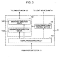
- the control unit 14 comprises a signal processing circuit 141 that performs signal processing on a reproduction signal based on the reproduction light obtained from the recording medium M, a driving section 142 that changes the orientation of the lens 121 on the basis of the processing result at the signal processing circuit 141, and a light-source-unit control section 143 that switches the light source unit 11 on the basis of the processing result at the signal processing circuit 141.
- the driving section 142 comprises a multiplex-direction driver 1421 and an arrangement-direction driver 1422.
- the multiplex-direction driver 1421 drives the lens in a direction of multiplexing hologram information with respect to the recording medium M, that is a direction (Bragg direction, a first direction) in which the irradiation angle with respect to the recording medium M is changed.
- the arrangement-direction driver 1422 drives the lens in a direction (second direction) in which the plurality of light sources are arranged in the light source unit 11.
- the first direction corresponds to a direction in which the orientation of the lens 121 is changed when reproducing information from the recording medium M, whereas the second direction corresponds to the direction of arrangement of the light sources in the light source array.
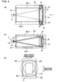
- Figs. 4(a) to 4(c) show the structure of the lens actuator in the hologram information reproducing device according to the first embodiment of the present invention, with Fig. 4(a) being a side view thereof, Fig. 4(b) being a top view thereof, and Fig. 4(c) showing the structure as viewed from the direction of an arrow shown in Fig. 4(a) .
- the lens 121 is mounted to a first supporting member 31.
- the first supporting member 31 and a second supporting member 33, disposed adjacent to the light source unit 11 so as to be separated from the first supporting member 31 by a predetermined interval, are such that their principal surfaces face each other.
- Four wires 32a to 32d are provided between the principal surfaces. That is, the four wires 32a to 32d are mounted, respectively, to four corners of the first supporting member 31 at one end; and are mounted, respectively, to four corners of the second supporting member 33 at the other end. This causes the lens 121 that is mounted to the first supporting member 31 to be suspended.
- a first coil 34 and a second coil 35 are disposed near the lens 121 of the first supporting member 32.
- the first coil 34 is disposed so that its longitudinal direction is positioned along a plane defined by the wires 32a and 32d and a plane defined by the wires 32b and 32c.
- the second coil 35 is disposed so that its longitudinal direction is positioned along a plane defined by the wires 32a and 32b and a plane defined by the wires 32c and 32d.
- Magnets 36 are disposed near the first coil 34 and the second coil 35. Each magnet 36 has a substantially rectangular annular form.
- the first coil 34 and the second coil 35 constitute a magnetic circuit.
- the lens actuator 123 by passing electrical current through the first coil 34, the lens 121 can be driven in accordance with the direction (second direction) of arrangement of the light sources 11a to 11c of the light source unit 11 (that is, the orientation of the lens 121 is driven horizontally).
- the lens 121 by passing electrical current through the second coil 35, the lens 121 can be driven in accordance with the direction (Bragg direction, first direction) in which the irradiation angle with respect to the recording medium M is changed (that is, the orientation of the lens 121 is driven vertically).
- the first direction and the second direction are set so as to be substantially perpendicular to each other. This makes it possible for the lens actuator 123 to drive the orientation of the lens 121 independently in the multiplex direction and the arrangement direction.
- the lens actuator 123 can drive the lens 121 in the multiplex direction and the arrangement direction.
- the information can be precisely reproduced, and the hologram information on which angle multiplexing is performed can be precisely reproduced.
- the hologram information reproducing device having the above-described structure, as shown in Figs. 1 and 2 , when light from the light source unit 11 is emitted, the light is converted into parallel light by the lens 121 of the optical system 12.
- the mirror 122 changes the orientation of the parallel light A so that it is oriented obliquely downward towards the recording medium M. More specifically, as shown in Fig. 1 , as viewed from the top, the mirror 122 changes a path of the light from the light source unit 11 by approximately 90 degrees. In addition, as shown in Fig. 2 , as viewed from the side, the mirror 122 changes the path of the light from the light source unit 11 downward by approximately 45 degrees.
- the interference pattern 25 recorded on the recording medium M is a Bragg grating
- the reproduction light B is obtained by Bragg diffraction. If the wavelength of the light (for reproduction information) from the light source unit 11 is substantially the same as the wavelength of the light for recording information, the hologram information recorded on a page can be reproduced.
- the reproduction light B is reflected by the reflecting layer 23 of the recording medium M, and is detected by the photodetector 13.
- the reproduction light B detected by the photodetector 13 is transmitted as a reproduction signal to the signal processing circuit 141 of the control unit 14 shown in Fig. 3 .
- the diffracted intensity of the reproduction signal is measured. If the measured diffracted intensity exceeds a predetermined value (threshold value), hologram information is obtained from the reproduction signal.
- the recording medium M expands or contracts due to external temperature
- information needs to be reproduced considering this expansion or contraction.
- light in a wavelength range of one light source may not be able to reproduce the information due to the external temperature than the information recording temperature.
- the light source is switched to a light source having a different wavelength range, to reproduce the information. More specifically, the diffracted intensity of reproduction light based on light emitted from one light source, such as the light source 11a shown in Fig. 4(b) , is measured.
- the light-source-unit control section 143 corrects the wavelength of the light source 11a by a predetermined amount, to measure the diffracted intensity of the reproduction light based on the light whose wavelength has been corrected. If, within the wavelength range of the light source 11a, the diffracted intensity of the reproduction light does not exceed a predetermined value, the light-source-unit control section 143 switches the light source unit 11. Here, the light source 11a is switched to the light source 11b. Then, similarly to the above, the diffracted intensity of reproduction light based on light emitted from the light source 11b is measured, to determine a threshold value with respect to the diffracted intensity. If the measured diffracted intensity exceeds the threshold value, hologram information is obtained from a reproduction signal thereof.
- a control signal for switching a light source by the light-source-unit control section 143 is sent not only to the light source unit 11, but also to the arrangement-direction driver 1422 of the driving section 142.
- a control signal that drives the orientation of the lens 121 in the light-source arrangement direction (second direction) is output to the lens actuator 123 in accordance with this control signal.
- the lens actuator 123 in accordance with this control signal, electrical current is passed through the first coil 34 to change the orientation of the lens 121 along the arrangement direction. Since the distances between the light sources 11a to 11c in the light source unit 11 are previously determined, when electrical current of an amount that is previously set in accordance with the distances is passed through the first coil 34, it is possible to change the orientation of the lens 121 by an angle that is shifted when the light source is switched.
- the orientation of the lens 121 needs to be changed by the lens actuator 123. That is, the orientation of the lens 121 is changed in accordance with the shifting of the irradiation angle that is changed when multiplexing is performed on the same recording area 24. This makes it possible to precisely reproduce the hologram information that is multiplexed at the same recording area 24. More specifically, from the signal processing circuit 141, a control signal for changing the multiplexing parameter is sent to the multiplex-direction driver 1421 of the driving section 142.
- a control signal that drives the orientation of the lens 121 in the multiplex direction (first direction) is output to the lens actuator 123 in accordance with this control signal.
- electrical current is passed through the second coil 35 to change the orientation of the lens 121 along the arrangement direction. Since the shifting amount of the irradiation angle when performing multiplexing recording is previously determined, when electrical current of an amount that is previously set in accordance with the shifting amount is passed through the second coil 35, it is possible to change the orientation of the lens 121 by an angle corresponding to the shifting amount of the irradiation angle.
- the diffracted intensity of reproduction light based on light emitted from the light source 11a is measured. If the diffracted intensity is less than a predetermined value, the angle of the lens 121 is corrected by a predetermined amount by the multiplex-direction driver 1421, to measure the diffracted intensity of the reproduction light based on the light whose irradiation angle has been corrected. If the measured diffracted intensity exceeds a threshold value, hologram information is obtained from a reproduction signal thereof. Ordinarily, the correction amount can be determined by, for example, PID control.
- the mirror 122 changes a path of the light from the light source unit 11 by approximately 90 degrees.
- the mirror 122 changes the path of the light from the light source unit 11 downward by approximately 45 degrees.
- the photodetector 13 is disposed on the same side as the light source unit 11 with respect to the recording medium M, compared to the structure in which the photodetector 13 is disposed opposite to the light source unit 11 with respect to the recording medium M, structural components can be concentrated on the same side with respect to the recording medium M, so that the size of the entire device can be reduced.
- the lens actuator 123 can drive the orientation of the lens 121 independently in the multiplex direction and the arrangement direction (biaxial directions), the lens actuator 123 can drive the lens 121 in the multiplex direction and the arrangement direction. Therefore, in reproducing hologram information, even if the light source unit 11 is switched, the information can be precisely reproduced, and the hologram information on which angle multiplexing is performed can be precisely reproduced.
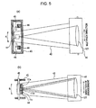
- FIGs. 5(a) and 5(b) illustrate the structure of a cylinder actuator in a hologram information reproducing device according to a second embodiment of the present invention, with Fig. 5(a) being a side view thereof and Fig. 5(b) being a top view thereof.
- Fig. 5 portions corresponding to those in Fig. 4 are given the same reference numerals as those in Fig. 4 , and will not be described in detail below.
- the hologram information reproducing device has the same structure as that of the first embodiment except that a cylinder actuator that changes the orientation of a cylinder is used instead of the lens actuator 123.
- a cylinder 42 has a structure in which a lens 121, which transmits light from a light source unit 11, and the light source unit 11 are integrated to each other. More specifically, in the cylinder actuator, the cylinder 42 is mounted to a supporting member 41. The supporting member 41 and the cylinder 42 are mounted to each other in, for example, a structure shown in Fig. 6 . As shown in Fig.
- the cylinder 42 is mounted to the supporting member 41 through a resilient plate 47, supporting portions 48a are provided between the resilient plate 47 and the cylinder 42, and supporting portions 48b are provided between the resilient plate 47 and the supporting member 41.
- the supporting portions 48a between the resilient member 47 and the cylinder 42 are disposed at positions that are vertically opposite to each other, and the supporting portions 48b between the resilient plate 47 and the supporting member 41 are disposed at positions that are horizontally opposite to each other. Accordingly, by interposing the resilient plate 47 between the supporting member 41 and the cylinder 42 using the supporting portions 48a and 48b, the cylinder 42 can be driven biaxially. As shown in Fig. 6(b) , even if ball bearings 49a are provided between the resilient plate 47 and the cylinder 42 and ball bearings 49b are provided between the resilient plate 47 and the supporting member 41, the cylinder 42 can be driven biaxially.
- a first coil 43 and a second coil 44 are disposed at a light-source-unit-11 (end) side of the cylinder 42. As shown in Fig. 5(a) , the first coil 43 is disposed so that its longitudinal direction is positioned along a side surface of the cylinder 42. The second coil 44 is disposed so that its longitudinal direction is positioned along the top surface and the bottom surface of the cylinder 42. Magnets 45 are disposed near the first coil 43 and the second coil 44. Each magnet 45 has a substantially rectangular annular form. The first coil 43 and the second coil 44 constitute a magnetic circuit.
- the cylinder 42 by passing electrical current through the first coil 43, the cylinder 42 can be driven in accordance with a direction (second direction) of arrangement of a plurality of light sources 11a to 11c of the light source unit 11 (that is, the orientation of the cylinder 42 can be driven horizontally).
- the second coil 44 by passing electrical current through the second coil 44, the cylinder 42 can be driven in accordance with a direction (Bragg direction, first direction) in which the irradiation angle with respect to a recording medium M is changed (that is, the orientation of the cylinder 42 is driven vertically).
- the first direction and the second direction are set so as to be substantially perpendicular to each other.
- the cylinder actuator can drive the orientation of the cylinder 42 independently in the multiplex direction and the arrangement direction. Therefore, the cylinder actuator can drive the lens 121 in the multiplex direction and the arrangement direction.
- the information can be precisely reproduced, and the hologram information on which angle multiplexing is performed can be precisely reproduced.
- the cylinder actuator changes the orientation of the cylinder 42 to change the orientation of the lens 121.
- the basic operations are similar to those in the first embodiment. That is, as viewed from the top, a mirror 122 changes a path of light from the light source unit 11 by approximately 90 degrees. In addition, as viewed from the side, the mirror 122 changes the path of the light from the light source unit 11 downward by approximately 45 degrees. Since an interference pattern 25 recorded on the recording medium M is a Bragg grating, when light A illuminates a recording area 24 of the recording medium M, reproduction light B is obtained by Bragg diffraction.
- the reproduction light B is reflected by a reflecting layer 23 of the recording medium M, and is detected by a photodetector 13.
- the reproduction light B detected by the photodetector 13 is transmitted as a reproduction signal to the signal processing circuit 141 of the control unit 14 shown in Fig. 3 .
- the diffracted intensity of the reproduction signal is measured. If the measured diffracted intensity exceeds a predetermined value (threshold value), hologram information is obtained from the reproduction signal.
- the recording medium M expands or contracts due to external temperature
- information needs to be reproduced considering this expansion or contraction as in the first embodiment.
- the light source 11a is switched to the light source 11b
- the position of the light source 11a and the position of the light source 11b differ from each other, it is necessary to change the orientation of the cylinder 42 by the cylinder actuator. That is, the orientation of the cylinder 42 is changed in accordance with a shift in the position of the light source.
- hologram information can be precisely reproduced using the reproduction light.
- a control signal for switching a light source by the light-source-unit control section 143 is sent not only to the light source unit 11, but also to the arrangement-direction driver 1422 of the driving section 142.
- a control signal that drives the orientation of the cylinder 42 in the light-source arrangement direction (second direction) is output to the cylinder actuator in accordance with this control signal.
- electrical current is passed through the first coil 43 to change the orientation of the cylinder 42 along the arrangement direction.
- the orientation of the cylinder 42 needs to be changed by the cylinder actuator. That is, the orientation of the cylinder 42 is changed in accordance with the shifting of the irradiation angle that is changed when multiplexing is performed on the same recording area 24. This makes it possible to precisely reproduce the hologram information that is multiplexed at the same recording area 24. More specifically, from the signal processing circuit 141, a control signal for changing the multiplexing parameter is sent to the multiplex-direction driver 1421 of the driving section 142.
- a control signal that drives the orientation of the cylinder 42 in the multiplex direction (first direction) is output to the cylinder actuator in accordance with this control signal.
- electrical current is passed through the second coil 44 to change the orientation of the cylinder 42 along the arrangement direction. Since the shifting amount of the irradiation angle when performing multiplexing recording is previously determined, when electrical current of an amount that is previously set in accordance with the shifting amount is passed through the second coil 44, it is possible to change the orientation of the lens 121 by an angle corresponding to the shifting amount of the irradiation angle.
- the diffracted intensity of reproduction light based on light emitted from the light source 11a is measured. If the diffracted intensity is less than a predetermined value, the angle of the cylinder 42 is corrected by a predetermined amount by the multiplex-direction driver 1421, to measure the diffracted intensity of the reproduction light based on the light whose irradiation angle has been corrected. If the measured diffracted intensity exceeds a threshold value, hologram information is obtained from a reproduction signal thereof. Ordinarily, the correction amount can be determined by, for example, PID control.
- the mirror 122 changes a path of the light from the light source unit 11 by approximately 90 degrees.
- the mirror 122 changes the path of the light from the light source unit 11 downward by approximately 45 degrees.
- the photodetector 13 is disposed on the same side as the light source unit 11 with respect to the recording medium M, compared to the structure in which the photodetector 13 is disposed opposite to the light source unit 11 with respect to the recording medium M, structural components can be concentrated on the same side with respect to the recording medium M, so that the size of the entire device can be reduced.
- the cylinder actuator can drive the orientation of the cylinder 42 independently in the multiplex direction and the arrangement direction (biaxial directions), the cylinder actuator can drive the lens 121 in the multiplex direction and the arrangement direction. Therefore, in reproducing hologram information, even if the light source unit 11 is switched, the information can be precisely reproduced, and the hologram information on which angle multiplexing is performed can be precisely reproduced.
- the present invention is not limited to the first and second embodiments, so that various modifications may be made to carry out the invention.
- the lens or the cylinder is driven using a magnetic circuit including a coil and a magnet
- the lens or the cylinder may be driven using a piezoelectric circuit which uses a piezo element in the present invention.
- other modifications may be made as appropriate within the scope of the object of the present invention, to carry out the invention.
Landscapes
- Holo Graphy (AREA)
- Optical Record Carriers And Manufacture Thereof (AREA)
- Optical Recording Or Reproduction (AREA)
- Optical Head (AREA)
Applications Claiming Priority (2)
| Application Number | Priority Date | Filing Date | Title |
|---|---|---|---|
| JP2005167379A JP4734037B2 (ja) | 2005-06-07 | 2005-06-07 | ホログラム情報再生装置 |
| PCT/JP2006/311056 WO2006132134A1 (ja) | 2005-06-07 | 2006-06-02 | ホログラム情報再生装置 |
Publications (3)
| Publication Number | Publication Date |
|---|---|
| EP1898403A1 EP1898403A1 (en) | 2008-03-12 |
| EP1898403A4 EP1898403A4 (en) | 2008-12-24 |
| EP1898403B1 true EP1898403B1 (en) | 2009-12-23 |
Family
ID=37498334
Family Applications (1)
| Application Number | Title | Priority Date | Filing Date |
|---|---|---|---|
| EP06747100A Ceased EP1898403B1 (en) | 2005-06-07 | 2006-06-02 | Hologram information reproducing device |
Country Status (6)
| Country | Link |
|---|---|
| US (1) | US7583424B2 (enExample) |
| EP (1) | EP1898403B1 (enExample) |
| JP (1) | JP4734037B2 (enExample) |
| CA (1) | CA2610984C (enExample) |
| DE (1) | DE602006011319D1 (enExample) |
| WO (1) | WO2006132134A1 (enExample) |
Family Cites Families (9)
| Publication number | Priority date | Publication date | Assignee | Title |
|---|---|---|---|---|
| JP4080195B2 (ja) | 2000-11-17 | 2008-04-23 | 松下電器産業株式会社 | ホログラフィック光情報記録再生装置 |
| US6958967B2 (en) * | 2000-11-17 | 2005-10-25 | Matsushita Electric Industrial Co., Ltd. | Holographic optical information recording/reproducing device |
| US6721076B2 (en) * | 2001-08-03 | 2004-04-13 | Inphase Technologies, Inc. | System and method for reflective holographic storage with associated multiplexing techniques |
| JP2004191683A (ja) * | 2002-12-11 | 2004-07-08 | Sony Corp | ホログラム記録再生装置、およびホログラム記録の再生装置 |
| JP4317911B2 (ja) * | 2003-07-08 | 2009-08-19 | 新オプトウエア株式会社 | 光情報記録装置および光情報再生装置 |
| JP2005150472A (ja) * | 2003-11-17 | 2005-06-09 | Alps Electric Co Ltd | 波長可変光源及びその製造方法 |
| JP4419616B2 (ja) * | 2004-03-16 | 2010-02-24 | Tdk株式会社 | ホログラフィック記録システム |
| JP2006085834A (ja) * | 2004-09-16 | 2006-03-30 | Optware:Kk | 光情報記録装置及び光情報再生装置 |
| JP2006301141A (ja) * | 2005-04-19 | 2006-11-02 | Alps Electric Co Ltd | ホログラム記録媒体用のピックアップおよびホログラム記録媒体の再生装置 |
-
2005
- 2005-06-07 JP JP2005167379A patent/JP4734037B2/ja not_active Expired - Fee Related
-
2006
- 2006-06-02 CA CA2610984A patent/CA2610984C/en not_active Expired - Fee Related
- 2006-06-02 DE DE602006011319T patent/DE602006011319D1/de active Active
- 2006-06-02 WO PCT/JP2006/311056 patent/WO2006132134A1/ja not_active Ceased
- 2006-06-02 EP EP06747100A patent/EP1898403B1/en not_active Ceased
-
2007
- 2007-12-07 US US11/952,400 patent/US7583424B2/en active Active
Also Published As
| Publication number | Publication date |
|---|---|
| WO2006132134A1 (ja) | 2006-12-14 |
| JP4734037B2 (ja) | 2011-07-27 |
| CA2610984C (en) | 2013-11-12 |
| CA2610984A1 (en) | 2006-12-14 |
| US20080137162A1 (en) | 2008-06-12 |
| DE602006011319D1 (de) | 2010-02-04 |
| JP2006344264A (ja) | 2006-12-21 |
| EP1898403A1 (en) | 2008-03-12 |
| EP1898403A4 (en) | 2008-12-24 |
| US7583424B2 (en) | 2009-09-01 |
Similar Documents
| Publication | Publication Date | Title |
|---|---|---|
| EP1282119B1 (en) | Optical pickup | |
| US20080094998A1 (en) | System for generating reference beam angle control signal and holographic information recording and/or reproducing apparatus employing the system | |
| KR20020037371A (ko) | 광 픽업 장치 | |
| EP2426663B1 (en) | Reproduction apparatus and reproduction method | |
| CN1649006A (zh) | 光学拾取器和记录/重放设备 | |
| US20080267039A1 (en) | Holographic recording apparatus, holographic reproducing apparatus and holographic recording and reproducing apparatus | |
| EP1129452A1 (en) | Optical pickup and servo control system for digital data storage | |
| US8085643B2 (en) | Optical information reproducing apparatus, optical information recording and reproducing apparatus | |
| US7903526B2 (en) | Recording/reproducing apparatus, method of reproducing data, and servo controlling method | |
| EP1898403B1 (en) | Hologram information reproducing device | |
| JP2007193852A (ja) | ホログラム記録担体 | |
| EP1881493A1 (en) | Information recording/reproducing device and information reproducing method | |
| US20080101196A1 (en) | Apparatus and method for record and/or reproduce holographic information | |
| EP1771849B1 (en) | Information carrier, system for reading said information carrier, method of manufacturing said information carrier | |
| US20070041302A1 (en) | Information recording apparatus, and information recording/reproducing apparatus | |
| EP1850336B1 (en) | Optical information reproducing apparatus and optical information recording apparatus using holography | |
| US20060039047A1 (en) | Holographic device | |
| WO2006090624A1 (ja) | ホログラム情報再生装置 | |
| US7538921B2 (en) | Hologram reproducing apparatus | |
| WO2005114336A1 (ja) | ホログラム装置 | |
| KR101422022B1 (ko) | 데이터 기록/재생 방법 및 장치 | |
| JP2007226908A (ja) | ホログラム記録方法、ホログラム再生方法、ホログラム再生装置 | |
| JP2008071449A (ja) | 光ピックアップ | |
| JPWO2008059832A1 (ja) | ホログラム再生装置及びホログラム再生方法 | |
| EP1831885A2 (en) | A reading device for a record carrier |
Legal Events
| Date | Code | Title | Description |
|---|---|---|---|
| PUAI | Public reference made under article 153(3) epc to a published international application that has entered the european phase |
Free format text: ORIGINAL CODE: 0009012 |
|
| 17P | Request for examination filed |
Effective date: 20080102 |
|
| AK | Designated contracting states |
Kind code of ref document: A1 Designated state(s): DE FR GB |
|
| RBV | Designated contracting states (corrected) |
Designated state(s): DE FR GB |
|
| DAX | Request for extension of the european patent (deleted) | ||
| A4 | Supplementary search report drawn up and despatched |
Effective date: 20081125 |
|
| GRAP | Despatch of communication of intention to grant a patent |
Free format text: ORIGINAL CODE: EPIDOSNIGR1 |
|
| GRAS | Grant fee paid |
Free format text: ORIGINAL CODE: EPIDOSNIGR3 |
|
| GRAA | (expected) grant |
Free format text: ORIGINAL CODE: 0009210 |
|
| AK | Designated contracting states |
Kind code of ref document: B1 Designated state(s): DE FR GB |
|
| REG | Reference to a national code |
Ref country code: GB Ref legal event code: FG4D |
|
| REF | Corresponds to: |
Ref document number: 602006011319 Country of ref document: DE Date of ref document: 20100204 Kind code of ref document: P |
|
| PLBE | No opposition filed within time limit |
Free format text: ORIGINAL CODE: 0009261 |
|
| STAA | Information on the status of an ep patent application or granted ep patent |
Free format text: STATUS: NO OPPOSITION FILED WITHIN TIME LIMIT |
|
| 26N | No opposition filed |
Effective date: 20100924 |
|
| REG | Reference to a national code |
Ref country code: FR Ref legal event code: PLFP Year of fee payment: 11 |
|
| REG | Reference to a national code |
Ref country code: FR Ref legal event code: PLFP Year of fee payment: 12 |
|
| REG | Reference to a national code |
Ref country code: DE Ref legal event code: R082 Ref document number: 602006011319 Country of ref document: DE Representative=s name: SCHMITT-NILSON SCHRAUD WAIBEL WOHLFROM PATENTA, DE |
|
| REG | Reference to a national code |
Ref country code: FR Ref legal event code: PLFP Year of fee payment: 13 |
|
| PGFP | Annual fee paid to national office [announced via postgrant information from national office to epo] |
Ref country code: DE Payment date: 20180625 Year of fee payment: 13 |
|
| PGFP | Annual fee paid to national office [announced via postgrant information from national office to epo] |
Ref country code: FR Payment date: 20180620 Year of fee payment: 13 |
|
| PGFP | Annual fee paid to national office [announced via postgrant information from national office to epo] |
Ref country code: GB Payment date: 20180620 Year of fee payment: 13 |
|
| REG | Reference to a national code |
Ref country code: DE Ref legal event code: R082 Ref document number: 602006011319 Country of ref document: DE Representative=s name: SCHMITT-NILSON SCHRAUD WAIBEL WOHLFROM PATENTA, DE Ref country code: DE Ref legal event code: R081 Ref document number: 602006011319 Country of ref document: DE Owner name: ALPS ALPINE CO., LTD., JP Free format text: FORMER OWNER: ALPS ELECTRIC CO., LTD., TOKIO/TOKYO, JP |
|
| REG | Reference to a national code |
Ref country code: DE Ref legal event code: R119 Ref document number: 602006011319 Country of ref document: DE |
|
| GBPC | Gb: european patent ceased through non-payment of renewal fee |
Effective date: 20190602 |
|
| PG25 | Lapsed in a contracting state [announced via postgrant information from national office to epo] |
Ref country code: GB Free format text: LAPSE BECAUSE OF NON-PAYMENT OF DUE FEES Effective date: 20190602 Ref country code: DE Free format text: LAPSE BECAUSE OF NON-PAYMENT OF DUE FEES Effective date: 20200101 |
|
| PG25 | Lapsed in a contracting state [announced via postgrant information from national office to epo] |
Ref country code: FR Free format text: LAPSE BECAUSE OF NON-PAYMENT OF DUE FEES Effective date: 20190630 |