EP1898279A2 - Portable electronic timepiece - Google Patents
Portable electronic timepiece Download PDFInfo
- Publication number
- EP1898279A2 EP1898279A2 EP07253563A EP07253563A EP1898279A2 EP 1898279 A2 EP1898279 A2 EP 1898279A2 EP 07253563 A EP07253563 A EP 07253563A EP 07253563 A EP07253563 A EP 07253563A EP 1898279 A2 EP1898279 A2 EP 1898279A2
- Authority
- EP
- European Patent Office
- Prior art keywords
- contact portion
- button shaft
- contact
- button
- main board
- Prior art date
- Legal status (The legal status is an assumption and is not a legal conclusion. Google has not performed a legal analysis and makes no representation as to the accuracy of the status listed.)
- Withdrawn
Links
Images




Classifications
-
- G—PHYSICS
- G04—HOROLOGY
- G04G—ELECTRONIC TIME-PIECES
- G04G17/00—Structural details; Housings
- G04G17/02—Component assemblies
- G04G17/04—Mounting of electronic components
-
- G—PHYSICS
- G04—HOROLOGY
- G04G—ELECTRONIC TIME-PIECES
- G04G21/00—Input or output devices integrated in time-pieces
Definitions
- the present invention relates to a module of an electronic timepiece.
- An electronic timepiece including a digital display portion is constituted generally by containing a timepiece module including a liquid crystal panel constituting a display element and a main board in a case.
- the main board is constituted by mounting an electronic part of IC or the like to a printed circuit board, and is provided with various functions of a time display function for displaying current time in digital at the liquid crystal panel based on an oscillation frequency of a quartz oscillator, an alarm function of generating an alarm based on alarm setting and the like.
- the printed circuit board is arranged with a contact portion, and an outer peripheral portion of the timepiece case is arranged with an operating portion including an operating button and a button shaft. The contact portion and the operating portion constitute a switch mechanism.
- the operating portion is provided with an operating spring, and the operating spring functions to separate a front end of the button shaft from the contact portion.
- the contact portion is a normal off contact, and a switching mechanism is a normal off switch.
- an electronic timepiece of a background art including a digital display portion needs a thickness for forming a guide hole for sliding to guide the button shaft of the operating portion at an outer peripheral portion of a case other than a thickness for forming a button containing recess portion. That is, the button containing recess portion for containing the operating button of the operating portion is formed at an outer peripheral face of the case, at the same time, a through hole constituting the guide hole is formed between a bottom face of the button containing recess portion and an inner peripheral face of the timepiece case.
- an outer peripheral portion of the case arranged with the operating portion that is, an interval between the outer peripheral face and the inner peripheral face thereof is more or less shorter than a sum of a length of a button shaft and a height of the operating button, the interval constitutes a considerable thickness in comparison with that of a case of a general electronic apparatus.
- the contact portion is arranged at a vicinity of an outer peripheral portion of a display area, and therefore, a space for arranging the contact portion is needed between the outer peripheral portion of the case and the vicinity of the outer peripheral portion of the display area.
- the electronic timepiece of the background art including the digital display portion although a size of the case needs to be reduced in order to downsize a product, since the guide hole for sliding to guide the button shaft of the operating button needs to be formed, the thickness of the outer peripheral portion of the case cannot be thinned. Therefore, according to the electronic timepiece of the background art including the digital display portion, downsizing a product is necessarily accompanied by downsizing the display area. Further, when downsizing the display area reduces a product value, the product cannot be downsized.
- a portable electronic timepiece constituted by including at least a timepiece module having a main board mounted with an electronic part on a printed circuit board and a display element for displaying time or the like, a case for containing the timepiece module, and.a switch mechanism arranged with an operating portion having an operating button at an outer periphery of the case, a button shaft of the operating button is arranged at a position planarly overlapping the display element, a contact portion of the switch mechanism is arranged on an extension in a direction of sliding the button shaft and at a position planarly overlapping the main board, and the main board and the contact portion are connected in a direction of a section thereof by connecting means.
- the outer peripheral portion of the case can be thinned to the thickness of only forming a recess for the push button, therefore, by the invention, the portable electronic timepiece can be downsized without reducing a display area. Further, light-weight formation of an exterior of the portable electronic timepiece can be achieved by the invention.
- a portable electronic timepiece is a portable electronic timepiece constituted by including at least a timepiece module having a main board mounted with an electronic part on a printed circuit board and a display element for displaying time or the like in digital, a case for containing the timepiece module, and a switch mechanism arranged with an operating portion having an operating button at an outer periphery of the case, in which a button shaft of the operating button is arranged at a position planarly overlapping the display element, a contact portion of the switch mechanism is arranged at a position on an extension of a direction of sliding the bottom shaft and planarly overlapping the main board, and the main board and the contact portion are connected by connecting means in a sectional direction.
- embodiment 1 of the invention is a portable electronic timepiece constituted by including at least a timepiece module 1 including a main board 11 mounted with an electronic part on a printed circuit board and a liquid crystal display element 12 for displaying time or the like in digital, a case 2 for containing the timepiece module 1, and a switch mechanism 3 arranged with an operating portion 30 including an operating button 31 at an outer peripheral portion 21 of the case 2.
- the timepiece module 1 is contained in a module containing recess portion 20 of the case 2, and is held at a containing position by a liquid crystal display element holder 6.
- a top side opening of the case 2 is sealed by a cover glass 5.
- a battery 7 is contained at a battery containing recess portion formed on a back side of the case, and an opening of the battery containing recess portion is sealed by a battery lid 8.
- the outer peripheral portion 21 of the case 2 is formed with push button containing recess portions 24 symmetrically in a left and right direction, and a button shaft guide hole 23 is formed at a button slidingly guide portion forming portion 22 of the case 2.
- the button slidingly guide portion forming portion 22 is a portion of the case 2 and a portion projected to an inner side of the case 2 from the outer peripheral portion 21, and therefore, is not related to a thickness of the outer peripheral portion 21. Further, the button slidingly guide portion forming portion 22 is constituted by a size of only forming the button shaft guide hole 23, and therefore, it is not necessary to change sizes and positions of the timepiece module 20 and the battery containing recess portion.
- connecting means 4 for connecting the switch mechanism 3 and the main board of embodiment 1 is constituted by using zebra rubber 40 of a rectangular parallelepiped arranged on an extension in a direction of sliding a button shaft 32 and a lower side of the main board 11, that is, at a position planarly overlapping the main board 11.
- the zebra rubber 40 is an electrically connecting part constituted by alternately laminating a plurality of conducting rubber plates and a plurality of insulating rubber plates.
- the zebra rubber 40 is an electrically connecting part providing a plurality of gold wires at three faces or four faces of an outer periphery of silicone rubber of a rectangular parallelepiped at intervals.
- a plurality of conducting portions are exposed at a button shaft opposed face of the zebra rubber 40 opposed to the button shaft 32 at equal intervals, at the same time, the plurality of conducting portions are exposed also at a main board opposed face opposed to a lower face of the main board 11 constituting a face orthogonal to the button shaft opposed face at equal intervals.
- the button shaft opposed face of the zebra rubber 40 constitutes a fixed contact portion 41 of the control portion of the switch mechanism 3.
- a movable contact portion of the contact portion of the switch mechanism 3, that is, a movable contact portion for opening/closing the fixed contact portion 41 is a bowl type rubber switch member 33 having a section in a channel-like shape.
- a conducting member 33a is provided at a center portion of the rubber switch member 33.
- the zebra rubbers 40 are respectively fixedly attached to left and right side faces of a contact member attaching portion 25 of the case 2 by making the fixed contact portions 41 constituting the button shaft opposed faces disposed at positions on the extension of the button shaft 32 and bringing section connecting portions 42 thereof into contact with connecting patterns 13a, 13b, 13c of a contact/main board connecting portion 13 of the main board 11.
- the button shaft 32 is inserted into the button shaft guide hole 23
- a front end thereof is brought into contact with a surface of the bowl type rubber switch member 33 having the section in the channel-like shape.
- the operating button 31 is contained in the button containing recess portion 24 formed at the outer peripheral portion 21 of the case 2.
- the portable electronic timepiece of embodiment 1 when the operating portions 30 each having the zebra rubber 40, the operating button 31 and the rubber switch member 33 are arranged at predetermined positions of the case 2, the switch mechanism 3 and the connecting means 4 for connecting the contact portion of the main board are simultaneously constituted. Further, according to the portable electronic timepiece of embodiment 1, a thickness of the outer peripheral portion 21 of the case 2 may be to a degree capable of forming the button containing recess portion 24, and therefore, downsizing a product is not influenced by the thickness of the outer peripheral portion 21 of the case. Therefore, the portable electronic timepiece of embodiment 1 can downsize a product without reducing a display area.
- a portable electronic timepiece of embodiment 2 of the invention is constructed by a constitution the same as that of embodiment 1 except the connecting means 4 for connecting the switch mechanism 3 and the main board. That is, when the plane view of Fig. 1, the sectional view of Fig. 2 cut by the line A-A of Fig. 1, the sectional view of Fig. 3 cut by the line B-B of Fig. 1, and the sectional view of Fig. 4 cut by the line C-C of Fig.
- the portable electronic timepiece of the embodiment of the invention is a portable electronic timepiece constituted by including at least the timepiece module 1 including the main board 11 mounted with an electronic part on the printed circuit board and the display element 12 for displaying time or the like in digital, the case 2 for containing the timepiece module 1, and the switch mechanism 3 arranging the operating portion 30 including the operating button 31 at the outer peripheral portion 21 of the case 2.
- the connecting means 4 for connecting the switch mechanism 3 and the main board of embodiment 2 is constituted by using a contact member 50 arranged on an extension in a direction of sliding the button shaft 32 and at a lower side of the main board 11, that is, at a position planarly overlapping the main board 11.
- the contact member 50 is a member integrally molded by interposing a T-like type insulating rubber member 50c by a pair of conducting rubbers 50a, 50b of a rectangular parallelepiped.
- Button shaft opposed faces of the pair of conducting rubbers 50a, 50b of the rectangular parallelepiped of the contact member 50 constitute a fixed contact portion 51 of the contact portion of the switch mechanism 3.
- a movable contact portion of the contact portion of the switch mechanism 3, that is, a movable contact portion for opening/closing the fixed contact portion 51 is the bowl type rubber switch member 33 having a section in the channel-like shape.
- the conducting member 33a is provided at the center portion of the rubber switch member 33.
- the contact members 50 are respectively fixedly attached to the left and right side faces of the contact member attaching portion 25 of the case 2 by making the fixed contact portions 51 constituting the button shaft opposed faces disposed on the extension of the button shaft 32 and bringing a section connecting portion 52 thereof into contact with the connecting patterns 13a, 13b, 13c of the contact/main board connecting portion 13 of the main board 11.
- the button shaft 32 is inserted into the button shaft guide hole 23
- the front end is brought into contact with the surface of the bowl type rubber switch member 33 having a section in the channel-like shape.
- the operating button 31 is contained in the button containing recess portion 24 formed at the outer peripheral portion 21 of the case 2.
- the portable electronic timepiece of embodiment 2 is a portable electronic timepiece characterized in that the contact member 50 integrally molded by interposing the T-type insulating rubber member 50c by the pair of conducting rubbers 50a, 50b of the rectangular parallelepiped is arranged on the extension in the direction of sliding the button shaft 32 and at the position planarly overlapping the main board 11, the button shaft opposed face of the contact member 50 is made to constitute the fixed contact portion 51, and the rubber switch member 33 switched on/off by the front end of the button shaft 32 is made to constitute the movable contact portion, further, the section connecting face 52 of the conducting rubbers 50a, 50b orthogonal to the button shaft opposed face of the contact member 50 is made to constitute connecting means for connecting the main board and the contact portion.
- the portable electronic timepiece of embodiment 2 when the contact member 50 integrally molded by interposing the T-type insulating rubber member 50c by the pair of conducting rubbers 50a, 50b of the rectangular parallelepiped, the operating portion 30 having the operating button 31 and the rubber switch 33 are arranged at predetermined positions of the case 2, the switch mechanism 3 and the connecting means 4 for connecting the contact portion and the main board are simultaneously constituted.
- a thickness of the outer peripheral portion 21 of the case 2 may be to a degree capable of forming the button containing recess portion 24, and therefore, downsizing the product is not influenced by the thickness of the outer peripheral portion 21 of the case. Therefore, also the portable electronic timepiece of embodiment 2 can downsize the product without reducing the display area.
- a portable electronic timepiece of embodiment 3 of the invention is constructed by a constitution the same as that of embodiment 1 except the connecting means 4 for connecting the switch mechanism 3 and the main board. That is, when the plane view of Fig. 1, the sectional view of Fig. 2 cut by the line A-A of Fig. 1, the sectional view of Fig. 3 cut by the line B-B of Fig. 1, and the sectional view of Fig. 4 cut by the line C-C of Fig.
- the portable electronic timepiece is a portable electronic timepiece constituted by including at least the timepiece module 1 including the main board 11 mounted with an electronic part on a printed circuit board and the display element 12 for displaying time or the like in digital, the case 2 for containing the timepiece module 1, and the switch mechanism 3 arranged with the operating portion 30 including the operating button 31 at the outer peripheral portion 21 of the case 2.
- the connecting means 4 for connecting the switch mechanism 3 and the main board of embodiment 3 is constituted by using a contact member 60 arranged on the extension in the direction of the sliding the button shaft 32 and the lower side of the main board 11, that is, the position planarly overlapping the main board 11 and a conducting rubber member 70 having an electricity conduction anisotropy as connecting means.
- the connecting member 60 is a member forming a pair of contact patterns 61 and connection line patterns 61a, 61b extended from the pair of contact patterns 61 to end faces thereof at a printed circuit board 60a for constituting the contact portion.
- a button shaft opposed face of the connecting member 60 formed with the pair of contact patterns 61 constitute a fixed contact portion 61 of the contact portion of the switch mechanism 3.
- the movable contact portion of the contact portion of the switch mechanism 3, that is, the movable contact portion for opening/closing the fixed contact portion 61 is the bowl type rubber switch member 33 having a section in a channel-like shape.
- a conducting member 33a is provided at a center portion of the rubber switch member 33.
- the contact members 60 are respectively fixedly attached to the left and right side faces of the contact member attaching portion 25 of the case 2 by making the fixed contact portion 61 formed with the pair of contact patterns disposed at a position on the extension of the button shaft 32, and bringing end faces extended with the connection line patterns 61a, 61b into contact with the one side face of the conducting rubber member 70 having the electricity conduction anisotropy.
- One surface of the conducting rubber member 70 having the electricity conduction anisotropy is brought into contact with the connecting patterns 13a, 13b, 13c of the contact/main board connecting portion 13 of the main board 11 and is fixed to the upper face of the contact member attaching portion 25 of the case 2.
- the button shaft 32 When the button shaft 32 is inserted into the button shaft guide hole 23, the front end is brought into contact with the surface of the bowl type rubber switch member 33 having a section in the channel-like shape. At the same time, the operating button 31 is contained in the button containing recess portion 24 formed at the outer peripheral portion 21 of the case 2.
- the portable electronic timepiece of embodiment 3 is a portable electronic timepiece characterized in that the contact member 60 formed with the pair of contact patterns 61 at the printed circuit board 60a for constituting the contact portion is arranged on the extension in the direction of sliding the button shaft 32 and at the position planarly overlapping the main board 11, the contact pattern 61 of the contact member 60 is made to constitute the fixed contact portion of the contact portion of the switch mechanism 3, and the rubber switch member 33 switched on/off by the front end of the button shaft 32 is made to constitute the movable contact portion of the contact portionof the switch mechanism 3, further, the conducting rubber 70 having the electricity conduction anisotropy is arranged as connecting means for connecting the connection lines 61a, 61b of the pair of connecting patterns 61 extended at the end face of the contact member 60 and the main board 11.
- the portable electronic timepiece of embodiment 3 when the contact member 60 forming the pair of contact patterns 61 at the printed circuit board 60a for constituting the contact portion, the operating portion 30 including the operating button 31, the conducting rubber 70 having the electricity conduction anisotropy and the rubber switch 33 are arranged at predetermined positions of the case 2, the switch mechanism 3 and the connecting means 4 for connecting the contact portion and the main board are simultaneously constituted.
- a thickness of the outer peripheral portion 21 of the case 2 may be to a degree capable of forming the button containing recess portion 24, and therefore, downsizing the product is not influenced by the thickness of the outer peripheral portion 21 of the case. Therefore, also the portable electronic timepiece of embodiment 3 can downsize the product without reducing the display area.
- the conducting rubber having the electricity conduction anisotropy is made to constitute the connecting means, a similar effect can be achieved also by connecting means by soldering or conductive adhering, soldering by way of a lead wire.
Landscapes
- Physics & Mathematics (AREA)
- General Physics & Mathematics (AREA)
- Electric Clocks (AREA)
- Push-Button Switches (AREA)
Abstract
Description
- The present invention relates to a module of an electronic timepiece.
- An electronic timepiece including a digital display portion is constituted generally by containing a timepiece module including a liquid crystal panel constituting a display element and a main board in a case. The main board is constituted by mounting an electronic part of IC or the like to a printed circuit board, and is provided with various functions of a time display function for displaying current time in digital at the liquid crystal panel based on an oscillation frequency of a quartz oscillator, an alarm function of generating an alarm based on alarm setting and the like. The printed circuit board is arranged with a contact portion, and an outer peripheral portion of the timepiece case is arranged with an operating portion including an operating button and a button shaft. The contact portion and the operating portion constitute a switch mechanism.
- The operating portion is provided with an operating spring, and the operating spring functions to separate a front end of the button shaft from the contact portion. The contact portion is a normal off contact, and a switching mechanism is a normal off switch. Hence, in setting time or setting alarm or the like, a user pushes the operating button against the operating spring. Then, the front end of the button shaft pushes the contact portion to switch the contact portion to an on state. In this way, the user carries out a predetermined input by pertinently operating the operating button while looking at a set screen displayed on the display panel.
- As described in
JP-A-2005-214795 - According to the electronic timepiece of the background art including the digital display portion, although a size of the case needs to be reduced in order to downsize a product, since the guide hole for sliding to guide the button shaft of the operating button needs to be formed, the thickness of the outer peripheral portion of the case cannot be thinned. Therefore, according to the electronic timepiece of the background art including the digital display portion, downsizing a product is necessarily accompanied by downsizing the display area. Further, when downsizing the display area reduces a product value, the product cannot be downsized.
- It is a problem of the invention to be resolved to provide a portable electronic timepiece capable of downsizing a product without reducing a display area.
- In order to resolve the problem, in a portable electronic timepiece constituted by including at least a timepiece module having a main board mounted with an electronic part on a printed circuit board and a display element for displaying time or the like, a case for containing the timepiece module, and.a switch mechanism arranged with an operating portion having an operating button at an outer periphery of the case, a button shaft of the operating button is arranged at a position planarly overlapping the display element, a contact portion of the switch mechanism is arranged on an extension in a direction of sliding the button shaft and at a position planarly overlapping the main board, and the main board and the contact portion are connected in a direction of a section thereof by connecting means.
- By the invention, the outer peripheral portion of the case can be thinned to the thickness of only forming a recess for the push button,
therefore, by the invention, the portable electronic timepiece can be downsized without reducing a display area. Further, light-weight formation of an exterior of the portable electronic timepiece can be achieved by the invention. - Embodiments of the present invention will now be described by way of further example only and with reference to the accompanying drawings, in which:
- Fig. 1 is a plane view of a portable electronic timepiece of
embodiment 1 of the invention. - Fig. 2 is a sectional view of the portable electronic timepiece of
embodiment 1 of the invention cut by a line A-A of Fig. 1. - Fig. 3 is a sectional view of the portable electronic timepiece of
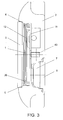
embodiment 1 of the invention cut by a line B-B of Fig. 1. - Fig. 4 is a sectional view of the portable electronic timepiece of
embodiment 1 of the invention cut by a line C-C of Fig. 1. - Fig. 5 is a part disassembled view of a portion including a switch mechanism and connecting means adopted in the portable electronic timepiece of
embodiment 1 of the invention. - Fig. 6 is a part disassembled view of a portion including a switch mechanism and connecting means adopted in a portable electronic timepiece of
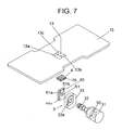
embodiment 2 of the invention. - Fig. 7 is a part disassembled view of a portion including a switch mechanism and connecting means adopted in a portable electronic timepiece of
embodiment 3 of the invention. - A portable electronic timepiece according to the invention is a portable electronic timepiece constituted by including at least a timepiece module having a main board mounted with an electronic part on a printed circuit board and a display element for displaying time or the like in digital, a case for containing the timepiece module, and a switch mechanism arranged with an operating portion having an operating button at an outer periphery of the case, in which a button shaft of the operating button is arranged at a position planarly overlapping the display element, a contact portion of the switch mechanism is arranged at a position on an extension of a direction of sliding the bottom shaft and planarly overlapping the main board, and the main board and the contact portion are connected by connecting means in a sectional direction.
- As shown by a plane view of Fig. 1, a sectional view of Fig. 2 cut by a line A-A of Fig. 1, a sectional view of Fig. 3 cut by a line B-B of Fig. 1, a sectional view of Fig. 4 cut by a line C-C of Fig. 1,
embodiment 1 of the invention is a portable electronic timepiece constituted by including at least atimepiece module 1 including amain board 11 mounted with an electronic part on a printed circuit board and a liquidcrystal display element 12 for displaying time or the like in digital, acase 2 for containing thetimepiece module 1, and aswitch mechanism 3 arranged with anoperating portion 30 including anoperating button 31 at an outerperipheral portion 21 of thecase 2. - The
timepiece module 1 is contained in a module containingrecess portion 20 of thecase 2, and is held at a containing position by a liquid crystaldisplay element holder 6. A top side opening of thecase 2 is sealed by acover glass 5. Abattery 7 is contained at a battery containing recess portion formed on a back side of the case, and an opening of the battery containing recess portion is sealed by abattery lid 8. - The outer
peripheral portion 21 of thecase 2 is formed with push button containingrecess portions 24 symmetrically in a left and right direction, and a buttonshaft guide hole 23 is formed at a button slidingly guideportion forming portion 22 of thecase 2. The button slidingly guideportion forming portion 22 is a portion of thecase 2 and a portion projected to an inner side of thecase 2 from the outerperipheral portion 21, and therefore, is not related to a thickness of the outerperipheral portion 21. Further, the button slidingly guideportion forming portion 22 is constituted by a size of only forming the buttonshaft guide hole 23, and therefore, it is not necessary to change sizes and positions of thetimepiece module 20 and the battery containing recess portion. - As shown by a part disassembled view of Fig. 5, connecting means 4 for connecting the
switch mechanism 3 and the main board ofembodiment 1 is constituted by usingzebra rubber 40 of a rectangular parallelepiped arranged on an extension in a direction of sliding abutton shaft 32 and a lower side of themain board 11, that is, at a position planarly overlapping themain board 11. Thezebra rubber 40 is an electrically connecting part constituted by alternately laminating a plurality of conducting rubber plates and a plurality of insulating rubber plates. Or, thezebra rubber 40 is an electrically connecting part providing a plurality of gold wires at three faces or four faces of an outer periphery of silicone rubber of a rectangular parallelepiped at intervals. In Fig. 5, a plurality of conducting portions are exposed at a button shaft opposed face of thezebra rubber 40 opposed to thebutton shaft 32 at equal intervals, at the same time, the plurality of conducting portions are exposed also at a main board opposed face opposed to a lower face of themain board 11 constituting a face orthogonal to the button shaft opposed face at equal intervals. - The button shaft opposed face of the
zebra rubber 40 constitutes afixed contact portion 41 of the control portion of theswitch mechanism 3. A movable contact portion of the contact portion of theswitch mechanism 3, that is, a movable contact portion for opening/closing thefixed contact portion 41 is a bowl typerubber switch member 33 having a section in a channel-like shape. A conductingmember 33a is provided at a center portion of therubber switch member 33. When the parts are integrated to thecase 2, theswitch mechanism 3 and theconnecting means 4 are simultaneously constituted. - That is, the
zebra rubbers 40 are respectively fixedly attached to left and right side faces of a contactmember attaching portion 25 of thecase 2 by making the fixedcontact portions 41 constituting the button shaft opposed faces disposed at positions on the extension of thebutton shaft 32 and bringingsection connecting portions 42 thereof into contact with connectingpatterns board connecting portion 13 of themain board 11. When thebutton shaft 32 is inserted into the buttonshaft guide hole 23, a front end thereof is brought into contact with a surface of the bowl typerubber switch member 33 having the section in the channel-like shape. At the same time, theoperating button 31 is contained in the button containingrecess portion 24 formed at the outerperipheral portion 21 of thecase 2. - As described above, according to the portable electronic timepiece of
embodiment 1, when theoperating portions 30 each having thezebra rubber 40, theoperating button 31 and therubber switch member 33 are arranged at predetermined positions of thecase 2, theswitch mechanism 3 and the connectingmeans 4 for connecting the contact portion of the main board are simultaneously constituted. Further, according to the portable electronic timepiece ofembodiment 1, a thickness of the outerperipheral portion 21 of thecase 2 may be to a degree capable of forming the button containingrecess portion 24, and therefore, downsizing a product is not influenced by the thickness of the outerperipheral portion 21 of the case. Therefore, the portable electronic timepiece ofembodiment 1 can downsize a product without reducing a display area. - A portable electronic timepiece of
embodiment 2 of the invention is constructed by a constitution the same as that ofembodiment 1 except theconnecting means 4 for connecting theswitch mechanism 3 and the main board. That is, when the plane view of Fig. 1, the sectional view of Fig. 2 cut by the line A-A of Fig. 1, the sectional view of Fig. 3 cut by the line B-B of Fig. 1, and the sectional view of Fig. 4 cut by the line C-C of Fig. 1 are referred, the portable electronic timepiece of the embodiment of the invention is a portable electronic timepiece constituted by including at least thetimepiece module 1 including themain board 11 mounted with an electronic part on the printed circuit board and thedisplay element 12 for displaying time or the like in digital, thecase 2 for containing thetimepiece module 1, and theswitch mechanism 3 arranging theoperating portion 30 including theoperating button 31 at the outerperipheral portion 21 of thecase 2. - As shown by a part disassembled view of Fig. 6, the
connecting means 4 for connecting theswitch mechanism 3 and the main board ofembodiment 2 is constituted by using acontact member 50 arranged on an extension in a direction of sliding thebutton shaft 32 and at a lower side of themain board 11, that is, at a position planarly overlapping themain board 11. Thecontact member 50 is a member integrally molded by interposing a T-like type insulatingrubber member 50c by a pair of conductingrubbers - Button shaft opposed faces of the pair of conducting
rubbers contact member 50 constitute a fixedcontact portion 51 of the contact portion of theswitch mechanism 3. A movable contact portion of the contact portion of theswitch mechanism 3, that is, a movable contact portion for opening/closing thefixed contact portion 51 is the bowl typerubber switch member 33 having a section in the channel-like shape. The conductingmember 33a is provided at the center portion of therubber switch member 33. When the parts are integrated to thecase 2, theswitch mechanism 3 and theconnecting means 4 are simultaneously constituted. - That is, the
contact members 50 are respectively fixedly attached to the left and right side faces of the contactmember attaching portion 25 of thecase 2 by making the fixedcontact portions 51 constituting the button shaft opposed faces disposed on the extension of thebutton shaft 32 and bringing asection connecting portion 52 thereof into contact with the connectingpatterns board connecting portion 13 of themain board 11. When thebutton shaft 32 is inserted into the buttonshaft guide hole 23, the front end is brought into contact with the surface of the bowl typerubber switch member 33 having a section in the channel-like shape. At the same time, theoperating button 31 is contained in the button containingrecess portion 24 formed at the outerperipheral portion 21 of thecase 2. - In sum, the portable electronic timepiece of
embodiment 2 is a portable electronic timepiece characterized in that thecontact member 50 integrally molded by interposing the T-type insulatingrubber member 50c by the pair of conductingrubbers button shaft 32 and at the position planarly overlapping themain board 11, the button shaft opposed face of thecontact member 50 is made to constitute the fixedcontact portion 51, and therubber switch member 33 switched on/off by the front end of thebutton shaft 32 is made to constitute the movable contact portion, further, thesection connecting face 52 of the conductingrubbers contact member 50 is made to constitute connecting means for connecting the main board and the contact portion. - According to the portable electronic timepiece of
embodiment 2, when thecontact member 50 integrally molded by interposing the T-type insulatingrubber member 50c by the pair of conductingrubbers portion 30 having the operatingbutton 31 and therubber switch 33 are arranged at predetermined positions of thecase 2, theswitch mechanism 3 and the connectingmeans 4 for connecting the contact portion and the main board are simultaneously constituted. Further, according to the portable electronic timepiece ofembodiment 2, a thickness of the outerperipheral portion 21 of thecase 2 may be to a degree capable of forming the button containingrecess portion 24, and therefore, downsizing the product is not influenced by the thickness of the outerperipheral portion 21 of the case. Therefore, also the portable electronic timepiece ofembodiment 2 can downsize the product without reducing the display area. - A portable electronic timepiece of
embodiment 3 of the invention is constructed by a constitution the same as that ofembodiment 1 except the connectingmeans 4 for connecting theswitch mechanism 3 and the main board. That is, when the plane view of Fig. 1, the sectional view of Fig. 2 cut by the line A-A of Fig. 1, the sectional view of Fig. 3 cut by the line B-B of Fig. 1, and the sectional view of Fig. 4 cut by the line C-C of Fig. 1 are referred, the portable electronic timepiece is a portable electronic timepiece constituted by including at least thetimepiece module 1 including themain board 11 mounted with an electronic part on a printed circuit board and thedisplay element 12 for displaying time or the like in digital, thecase 2 for containing thetimepiece module 1, and theswitch mechanism 3 arranged with the operatingportion 30 including theoperating button 31 at the outerperipheral portion 21 of thecase 2. - As shown by a part disassembled view of Fig. 7, the connecting
means 4 for connecting theswitch mechanism 3 and the main board ofembodiment 3 is constituted by using acontact member 60 arranged on the extension in the direction of the sliding thebutton shaft 32 and the lower side of themain board 11, that is, the position planarly overlapping themain board 11 and a conductingrubber member 70 having an electricity conduction anisotropy as connecting means. The connectingmember 60 is a member forming a pair ofcontact patterns 61 andconnection line patterns contact patterns 61 to end faces thereof at a printedcircuit board 60a for constituting the contact portion. - A button shaft opposed face of the connecting
member 60 formed with the pair ofcontact patterns 61 constitute a fixedcontact portion 61 of the contact portion of theswitch mechanism 3. The movable contact portion of the contact portion of theswitch mechanism 3, that is, the movable contact portion for opening/closing the fixedcontact portion 61 is the bowl typerubber switch member 33 having a section in a channel-like shape. A conductingmember 33a is provided at a center portion of therubber switch member 33. When the parts are integrated to thecase 2, theswitch mechanism 3 and the connectingmeans 4 are simultaneously constituted. - That is, the
contact members 60 are respectively fixedly attached to the left and right side faces of the contactmember attaching portion 25 of thecase 2 by making the fixedcontact portion 61 formed with the pair of contact patterns disposed at a position on the extension of thebutton shaft 32, and bringing end faces extended with theconnection line patterns rubber member 70 having the electricity conduction anisotropy. One surface of the conductingrubber member 70 having the electricity conduction anisotropy is brought into contact with the connectingpatterns board connecting portion 13 of themain board 11 and is fixed to the upper face of the contactmember attaching portion 25 of thecase 2. When thebutton shaft 32 is inserted into the buttonshaft guide hole 23, the front end is brought into contact with the surface of the bowl typerubber switch member 33 having a section in the channel-like shape. At the same time, theoperating button 31 is contained in the button containingrecess portion 24 formed at the outerperipheral portion 21 of thecase 2. - In sum, the portable electronic timepiece of
embodiment 3 is a portable electronic timepiece characterized in that thecontact member 60 formed with the pair ofcontact patterns 61 at the printedcircuit board 60a for constituting the contact portion is arranged on the extension in the direction of sliding thebutton shaft 32 and at the position planarly overlapping themain board 11, thecontact pattern 61 of thecontact member 60 is made to constitute the fixed contact portion of the contact portion of theswitch mechanism 3, and therubber switch member 33 switched on/off by the front end of thebutton shaft 32 is made to constitute the movable contact portion of the contact portionof theswitch mechanism 3, further, the conductingrubber 70 having the electricity conduction anisotropy is arranged as connecting means for connecting theconnection lines patterns 61 extended at the end face of thecontact member 60 and themain board 11. - According to the portable electronic timepiece of
embodiment 3, when thecontact member 60 forming the pair ofcontact patterns 61 at the printedcircuit board 60a for constituting the contact portion, the operatingportion 30 including theoperating button 31, the conductingrubber 70 having the electricity conduction anisotropy and therubber switch 33 are arranged at predetermined positions of thecase 2, theswitch mechanism 3 and the connectingmeans 4 for connecting the contact portion and the main board are simultaneously constituted. Further, according to the portable electronic timepiece ofembodiment 3, a thickness of the outerperipheral portion 21 of thecase 2 may be to a degree capable of forming the button containingrecess portion 24, and therefore, downsizing the product is not influenced by the thickness of the outerperipheral portion 21 of the case. Therefore, also the portable electronic timepiece ofembodiment 3 can downsize the product without reducing the display area. Further, although according to the embodiment, the conducting rubber having the electricity conduction anisotropy is made to constitute the connecting means, a similar effect can be achieved also by connecting means by soldering or conductive adhering, soldering by way of a lead wire. - The aforegoing description has been given by way of example only and it will be appreciated by a person skilled in the art that modifications can be made without departing from the scope of the present invention.
Claims (5)
- A portable electronic timepiece characterized in that, in a portable electronic timepiece constituted by including at least a timepiece module having a main board mounted with an electronic part on a printed circuit board and a display element for displaying time or the like, a case for containing the timepiece module, and a switch mechanism arranged with an operating portion having an operating button at an outer periphery of the case;
a button shaft of the operating button is arranged at a position planarly overlapping the display element, a contact portion of the switch mechanism is arranged on an extension in a direction of sliding the button shaft and at a position planarly overlapping the main board, and the main board and the contact portion are connected in a direction of a section thereof by connecting means. - The portable electronic timepiece according to Claim 1, characterized in that a connecting rubber of a rectangular parallelepiped constituted by alternately laminating a plurality of conducting rubbers and a plurality of insulating rubbers is arranged on the extension in the direction of sliding the button shaft and at the position planarly overlapping the main board, a button shaft opposed face opposed to a front end of the button shaft of the connecting rubber is made to constitute a fixed contact portion of the contact portion, a rubber switch member switched on/off by the front end of the button shaft is made to constitute a movable contact portion of the contact portion, and a face of the connecting rubber orthogonal to the button shaft opposed face is made to constitute a section connecting face constituting connecting means for connecting the main board and the contact portion.
- The portable electronic timepiece according to Claim 1, characterized in that a contact member integrally molded by interposing a T-type insulating rubber member by a pair of conducting rubbers of a rectangular parallelepiped is arranged on the extension in the direction of sliding the button shaft and at a position planarly overlapping the main board, a button shaft opposed face of the contact member opposed to the front end of the button shaft is made to constitute a fixed contact portion of the contact portion, a rubber switch member switched on/off by the front end of the button shaft is made to constitute a movable contact portion of the contact portion, and a section connecting face of the conducting rubber orthogonal to the button shaft opposed face of the contact member is made to constitute connecting means for connecting the main board and the contact portion.
- The portable electronic timepiece according to Claim 1, characterized in that a contact member forming a pair of contact patterns on a printed circuit board for constituting a contact portion is arranged on the extension in the direction of sliding the button shaft and at a position planarly overlapping the main board, a contact pattern forming face of the contact member opposed to a front end of the button shaft is made to constitute a fixed contact portion of the contact portion, a rubber switch member switched on/off by the front end of the button shaft is made to constitute a movable contact portion of the contact portion, and connecting means for connecting connecting lines of the pair of contact patterns extended to an end face of the contact member and the main board is arranged.
- The portable electronic timepiece according to Claim 4, characterized in that the connecting means is a conducting rubber having electricity conduction anisotropy.
Applications Claiming Priority (1)
| Application Number | Priority Date | Filing Date | Title |
|---|---|---|---|
| JP2006242879A JP4820720B2 (en) | 2006-09-07 | 2006-09-07 | Portable electronic watch |
Publications (2)
| Publication Number | Publication Date |
|---|---|
| EP1898279A2 true EP1898279A2 (en) | 2008-03-12 |
| EP1898279A3 EP1898279A3 (en) | 2009-02-25 |
Family
ID=38895956
Family Applications (1)
| Application Number | Title | Priority Date | Filing Date |
|---|---|---|---|
| EP07253563A Withdrawn EP1898279A3 (en) | 2006-09-07 | 2007-09-07 | Portable electronic timepiece |
Country Status (3)
| Country | Link |
|---|---|
| US (1) | US7646677B2 (en) |
| EP (1) | EP1898279A3 (en) |
| JP (1) | JP4820720B2 (en) |
Families Citing this family (30)
| Publication number | Priority date | Publication date | Assignee | Title |
|---|---|---|---|---|
| JP2009224057A (en) | 2008-03-13 | 2009-10-01 | Alps Electric Co Ltd | Stoke switch device |
| KR101650383B1 (en) * | 2010-04-09 | 2016-08-23 | 엘지전자 주식회사 | Mobile terminal |
| US9753436B2 (en) | 2013-06-11 | 2017-09-05 | Apple Inc. | Rotary input mechanism for an electronic device |
| CN109634447B (en) | 2013-08-09 | 2022-04-19 | 苹果公司 | Tactile switch for electronic devices |
| WO2015122885A1 (en) | 2014-02-12 | 2015-08-20 | Bodhi Technology Ventures Llc | Rejection of false turns of rotary inputs for electronic devices |
| US10190891B1 (en) | 2014-07-16 | 2019-01-29 | Apple Inc. | Optical encoder for detecting rotational and axial movement |
| US10599101B2 (en) | 2014-09-02 | 2020-03-24 | Apple Inc. | Wearable electronic device |
| KR101940943B1 (en) | 2015-03-05 | 2019-01-21 | 애플 인크. | Optical encoder with direction dependent optical properties |
| WO2016144919A1 (en) | 2015-03-08 | 2016-09-15 | Apple Inc. | Compressible seal for rotatable and translatable input mechanisms |
| US10018966B2 (en) | 2015-04-24 | 2018-07-10 | Apple Inc. | Cover member for an input mechanism of an electronic device |
| US9891651B2 (en) | 2016-02-27 | 2018-02-13 | Apple Inc. | Rotatable input mechanism having adjustable output |
| US10551798B1 (en) | 2016-05-17 | 2020-02-04 | Apple Inc. | Rotatable crown for an electronic device |
| US10061399B2 (en) | 2016-07-15 | 2018-08-28 | Apple Inc. | Capacitive gap sensor ring for an input device |
| US10019097B2 (en) | 2016-07-25 | 2018-07-10 | Apple Inc. | Force-detecting input structure |
| US10664074B2 (en) | 2017-06-19 | 2020-05-26 | Apple Inc. | Contact-sensitive crown for an electronic watch |
| US10962935B1 (en) | 2017-07-18 | 2021-03-30 | Apple Inc. | Tri-axis force sensor |
| US11360440B2 (en) | 2018-06-25 | 2022-06-14 | Apple Inc. | Crown for an electronic watch |
| US11561515B2 (en) | 2018-08-02 | 2023-01-24 | Apple Inc. | Crown for an electronic watch |
| US11181863B2 (en) | 2018-08-24 | 2021-11-23 | Apple Inc. | Conductive cap for watch crown |
| US12259690B2 (en) | 2018-08-24 | 2025-03-25 | Apple Inc. | Watch crown having a conductive surface |
| CN209560398U (en) | 2018-08-24 | 2019-10-29 | 苹果公司 | digital watch |
| US11194298B2 (en) | 2018-08-30 | 2021-12-07 | Apple Inc. | Crown assembly for an electronic watch |
| CN209625187U (en) | 2018-08-30 | 2019-11-12 | 苹果公司 | Electronic Watches and Electronic Devices |
| US11194299B1 (en) | 2019-02-12 | 2021-12-07 | Apple Inc. | Variable frictional feedback device for a digital crown of an electronic watch |
| KR102861687B1 (en) * | 2019-07-02 | 2025-09-18 | 삼성전자주식회사 | Electronic device including electrically connecting member |
| US11550268B2 (en) | 2020-06-02 | 2023-01-10 | Apple Inc. | Switch module for electronic crown assembly |
| US11983035B2 (en) | 2020-06-11 | 2024-05-14 | Apple Inc. | Electronic device |
| US12092996B2 (en) | 2021-07-16 | 2024-09-17 | Apple Inc. | Laser-based rotation sensor for a crown of an electronic watch |
| US12189347B2 (en) | 2022-06-14 | 2025-01-07 | Apple Inc. | Rotation sensor for a crown of an electronic watch |
| US12596334B2 (en) | 2023-02-07 | 2026-04-07 | Apple Inc. | Crown for an electronic watch |
Family Cites Families (12)
| Publication number | Priority date | Publication date | Assignee | Title |
|---|---|---|---|---|
| JPS5140095A (en) | 1974-09-30 | 1976-04-03 | Sharp Kk | |
| US4092821A (en) * | 1975-12-02 | 1978-06-06 | Wirz Carl A | Control device for an electronic watch |
| JPS5367473A (en) * | 1976-11-29 | 1978-06-15 | Hitachi Seiko Ltd | Speed detector |
| US4170104A (en) | 1976-12-01 | 1979-10-09 | Citizen Watch Company Limited | Switch mechanism for wristwatch |
| JPS53125072A (en) | 1977-04-07 | 1978-11-01 | Seiko Epson Corp | Fully electronic wristwatch |
| JPS5619790A (en) * | 1979-07-26 | 1981-02-24 | Toshiba Corp | Recording medium |
| JPH01170921A (en) * | 1987-12-25 | 1989-07-06 | Iwatsu Electric Co Ltd | Optical heterodyne detection device |
| ATE192858T1 (en) | 1996-12-02 | 2000-05-15 | Ebauchesfabrik Eta Ag | ELECTRICAL SWITCHING DEVICE ON A PRINTED CIRCUIT AND CLOCK CONTAINING SUCH DEVICE |
| ATE478366T1 (en) * | 2000-03-17 | 2010-09-15 | Eta Sa Mft Horlogere Suisse | DEVICE FOR EXCHANGING INFORMATION WITH A WEARABLE OBJECT, IN PARTICULAR A WRISTWATCH |
| ATE331326T1 (en) * | 2003-09-23 | 2006-07-15 | Asulab Sa | ADAPTER FOR A PORTABLE ELECTRONIC DEVICE AND TRANSMISSION SYSTEM BETWEEN SUCH COMPONENTS |
| EP1519453B1 (en) * | 2003-09-23 | 2006-06-28 | Asulab S.A. | Portable electronic equipment having at least one I/O terminal adapted for establishing a connection with an electronic unit located within said equipment |
| JP4443250B2 (en) | 2004-01-29 | 2010-03-31 | セイコーインスツル株式会社 | Portable multifunction electronic watch |
-
2006
- 2006-09-07 JP JP2006242879A patent/JP4820720B2/en not_active Expired - Fee Related
-
2007
- 2007-09-06 US US11/899,663 patent/US7646677B2/en not_active Expired - Fee Related
- 2007-09-07 EP EP07253563A patent/EP1898279A3/en not_active Withdrawn
Also Published As
| Publication number | Publication date |
|---|---|
| EP1898279A3 (en) | 2009-02-25 |
| JP2008064607A (en) | 2008-03-21 |
| US7646677B2 (en) | 2010-01-12 |
| JP4820720B2 (en) | 2011-11-24 |
| US20080062820A1 (en) | 2008-03-13 |
Similar Documents
| Publication | Publication Date | Title |
|---|---|---|
| US7646677B2 (en) | Portable electronic timepiece | |
| KR0132404B1 (en) | Electric device with a liquid crystal display | |
| EP1634127B1 (en) | Multi functional timepiece module with application specific printed circuit boards | |
| CN107589661B (en) | Modules and Clocks | |
| US4120039A (en) | Electronic digital watch combined with a computer | |
| CN104871095B (en) | Portable touch electronic object | |
| US3975899A (en) | Multi-function watch casing | |
| JP6547710B2 (en) | Module and watch | |
| GB2338830A (en) | An electrical switch actuator which is integral with its housing | |
| JP3700339B2 (en) | Electronic equipment with antenna | |
| JP2002148367A (en) | Multifunction wristwatch | |
| JP5428082B2 (en) | Electronics | |
| JP2008198051A (en) | Electronic pedometer | |
| CN220855468U (en) | Electronic clock capable of improving human body induction stability of keys | |
| JP2007263646A (en) | Equipment module | |
| JP6842643B2 (en) | Modules and clocks | |
| CN1708734B (en) | Button control device and portable electronic instrument including the same | |
| JPH0623992Y2 (en) | Electronic watch clock case | |
| JPS6318036Y2 (en) | ||
| JPS6052394B2 (en) | electronic watch | |
| JPS59157588A (en) | Structure of liquid-crystal display type timepiece | |
| JP2002286880A (en) | Electronic watch | |
| KR101366319B1 (en) | A keypad and A communication device thereof | |
| JP2571037Y2 (en) | LCD mounting structure | |
| GB2322460A (en) | Digital and analogue display wrist watch |
Legal Events
| Date | Code | Title | Description |
|---|---|---|---|
| PUAI | Public reference made under article 153(3) epc to a published international application that has entered the european phase |
Free format text: ORIGINAL CODE: 0009012 |
|
| AK | Designated contracting states |
Kind code of ref document: A2 Designated state(s): AT BE BG CH CY CZ DE DK EE ES FI FR GB GR HU IE IS IT LI LT LU LV MC MT NL PL PT RO SE SI SK TR |
|
| AX | Request for extension of the european patent |
Extension state: AL BA HR MK YU |
|
| PUAL | Search report despatched |
Free format text: ORIGINAL CODE: 0009013 |
|
| AK | Designated contracting states |
Kind code of ref document: A3 Designated state(s): AT BE BG CH CY CZ DE DK EE ES FI FR GB GR HU IE IS IT LI LT LU LV MC MT NL PL PT RO SE SI SK TR |
|
| AX | Request for extension of the european patent |
Extension state: AL BA HR MK RS |
|
| AKX | Designation fees paid | ||
| REG | Reference to a national code |
Ref country code: DE Ref legal event code: 8566 |
|
| STAA | Information on the status of an ep patent application or granted ep patent |
Free format text: STATUS: THE APPLICATION IS DEEMED TO BE WITHDRAWN |
|
| 18D | Application deemed to be withdrawn |
Effective date: 20090825 |