EP1898209A1 - Inverse thermal acoustic imaging part inspection - Google Patents
Inverse thermal acoustic imaging part inspection Download PDFInfo
- Publication number
- EP1898209A1 EP1898209A1 EP07253415A EP07253415A EP1898209A1 EP 1898209 A1 EP1898209 A1 EP 1898209A1 EP 07253415 A EP07253415 A EP 07253415A EP 07253415 A EP07253415 A EP 07253415A EP 1898209 A1 EP1898209 A1 EP 1898209A1
- Authority
- EP
- European Patent Office
- Prior art keywords
- heat
- flaw
- thermal image
- surface temperature
- processor
- Prior art date
- Legal status (The legal status is an assumption and is not a legal conclusion. Google has not performed a legal analysis and makes no representation as to the accuracy of the status listed.)
- Granted
Links
Images

Classifications
-
- G—PHYSICS
- G01—MEASURING; TESTING
- G01N—INVESTIGATING OR ANALYSING MATERIALS BY DETERMINING THEIR CHEMICAL OR PHYSICAL PROPERTIES
- G01N25/00—Investigating or analyzing materials by the use of thermal means
- G01N25/72—Investigating presence of flaws
Definitions
- This invention relates to a method and apparatus for inspecting a part to identify, for example, flaws within the part.
- a method of identifying a flaw in a part includes vibrating a part to induce heat.
- the heat originates in any flaws in the part.
- a thermal image is obtained using, for example, an infrared camera.
- a mathematical representation which could be any of a number of analytical modeling methods such as the boundary element method or the finite element method, is used in conjunction with heat transfer equations to identify a source and an intensity of the heat identified with the thermal image. Using the source and intensity of the heat, flaw characteristics for the part can be determined.
- the above method is employed using an inspection system that includes a vibration device for vibrating the part.
- An imaging device such as an infrared camera, measures the temperature on the surface of the part.
- a processor communicates with the imaging device for receiving the surface temperature.
- the processor includes a computer memory having part characteristics and mathematical equations. The processor uses the surface temperature, part characteristics and mathematical equations to determine the flaw characteristics in the part.
- FIG. 1 An inspection system 11 for identifying features within a part 10 such as a flaw is illustrated in Figure 1.
- the inspection system 11 can be fully automated.
- the part 10 having a flaw 12 is mounted on a vibration device 30 that is excited using multiple actuators 32 of different frequency.
- the vibration device 30 may be a shaker table or ultrasonic devices capable of vibrating the part 10 in a range of, for example, 500 Hz-100 kHz.
- a computer 14 is schematically shown in Figure 1 including a processor 16 and memory 18.
- the computer 14 includes an output device 20 such as a display.
- the display 20 can graphically and/or textually illustrate any flaw characteristics 22 identified during the part inspection for subsequent analysis.
- part characteristics 24 such as a part model 26 may be provided in the memory 18.
- the part model 26 can be, for example, boundary element information, which graphically and mathematically represents the structural features of the part 10.
- the part characteristics 24 can be input into the computer 14 using an input device 21.
- the memory 18 includes mathematical model 36 that relates the surface temperature information obtained from the infrared camera 34 to one or more flaws within the part 10 using the part characteristics 24.
- Step 1 includes initiating an acoustic vibration of the part 10 using the vibration device 30. Any surface, sub-surface or buried flaws or cracks will generate heat 33.
- Step 2 includes obtaining a thermal image of the part 10 using the infrared camera 34. Several images can be taken to capture the transient temperature over the test so it can be compared to the base line temperature of the part 10. The images obtained by the infrared camera 34 are digitized to obtain thermal information such as surface temperature relating to the part 10 in the example illustrated at Step 3. Various sets of digitized thermal images are obtained under different loading conditions such as signal duration, signal parameters and acquisition time, for example.
- Step 4 includes using the measured surface temperatures, ambient temperature, and surface heat fluxes or surface heat transfer coefficients either assumed or measured on the surface of the part, to inversely solve the transient heat transfer equation to predict unknown heat sources produced by the cracks or flaws.
- the thermal information is related to a boundary element model that graphically represents the part 10.
- III-posed transient heat transfer equations of the part 10 are solved for the heat sources in Step 5 using the boundary element method or finite element method, for example.
- the result of this inverse solution is the prediction of the unknown heat source intensity and locations.
- a boundary element method matrix conditioning method is used to solve the system of algebraic equations by regularization.
- the ill-conditioned system of equations is conditioned by eliminating singular and near-singular equations that are corrupted by round-off error, as represented by Step 5a.
- the heat source intensity is obtained in each numerical grid cell of the boundary element model, as illustrated at Step 6.
- Step 7 converts the heat source and intensity information to crack geometry and position information.
- Step 7a references preliminary material testing and modeling information.
- the preliminary material information includes known friction coefficients and energy release rates from known crack geometry, which can be gathered empirically and allows an effective filtering of the initial inverse solution.
- Step 7b arrives at an initial approximation for the crack distribution.
- the crack distributions can be refined using an iterative or numerical method such as the method of least squares. The numerical method minimizes the differences between the energy convergence rate and predictions relating to the heat sources.
- the internal crack sizes and positions can be calculated. This information is then used to determine whether the part 10 should be accepted or rejected, as indicated at Step 8.
Landscapes
- General Health & Medical Sciences (AREA)
- Health & Medical Sciences (AREA)
- Life Sciences & Earth Sciences (AREA)
- Chemical & Material Sciences (AREA)
- Analytical Chemistry (AREA)
- Biochemistry (AREA)
- Physics & Mathematics (AREA)
- General Physics & Mathematics (AREA)
- Immunology (AREA)
- Pathology (AREA)
- Investigating Or Analyzing Materials Using Thermal Means (AREA)
- Radiation Pyrometers (AREA)
- Investigating Or Analyzing Materials By The Use Of Ultrasonic Waves (AREA)
Abstract
Description
- This invention relates to a method and apparatus for inspecting a part to identify, for example, flaws within the part.
- Many component parts must be examined to ensure that there are no part defects that would compromise their use. This is particularly true in the case of aircraft components such as turbine airfoils. The part must be examined in a non-destructive manner so that the part can still be used after examination. It is difficult to detect some part flaws such as small cracks. Further, any internal part defects may not become evident using traditional non-destructive inspection techniques such as ultrasound, x-ray, fluorescent penetrants or eddy current.
- What is needed is a non-destructive inspection method and apparatus that is capable of identifying part flaws such as cracks.
- A method of identifying a flaw in a part is provided that includes vibrating a part to induce heat. The heat originates in any flaws in the part. A thermal image is obtained using, for example, an infrared camera. A mathematical representation, which could be any of a number of analytical modeling methods such as the boundary element method or the finite element method, is used in conjunction with heat transfer equations to identify a source and an intensity of the heat identified with the thermal image. Using the source and intensity of the heat, flaw characteristics for the part can be determined.
- The above method is employed using an inspection system that includes a vibration device for vibrating the part. An imaging device, such as an infrared camera, measures the temperature on the surface of the part. A processor communicates with the imaging device for receiving the surface temperature. The processor includes a computer memory having part characteristics and mathematical equations. The processor uses the surface temperature, part characteristics and mathematical equations to determine the flaw characteristics in the part.
- These and other features of the present invention can be best understood from the following specification and drawings, which are given by way of example and not limitation.
-
- Figure 1 is a schematic view of an example inspection system used for identifying a flaw in a part.
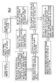
- Figure 2 is a flow chart depicting a method of identifying a flaw in the part.
- An inspection system 11 for identifying features within a
part 10 such as a flaw is illustrated in Figure 1. The inspection system 11 can be fully automated. Thepart 10 having aflaw 12 is mounted on avibration device 30 that is excited usingmultiple actuators 32 of different frequency. Thevibration device 30 may be a shaker table or ultrasonic devices capable of vibrating thepart 10 in a range of, for example, 500 Hz-100 kHz. - Due to the vibration imparted to the
part 10 by thevibration device 30, heat is generated at any flaws or cracks within thepart 10 due to friction and plastic deformation during each loading cycle. This heating, which is illustrated schematically at 33, results in a temperature rise over the nominal structure temperature of thepart 10. The temperature rise caused by a crack is distributed over a range wider than the strained distortion and, hence, can be detected using aninfrared camera 34, for example. Images of the exterior of thepart 10 are taken by theinfrared camera 34. The temperature rise depends upon crack geometry, location, and energy dissipation within the elastic-plastic structure and friction of the flaws' banks of thepart 10. The energy dissipation or release rate of heat can be parameterized during material modeling, or can be obtained empirically using a known crack geometry. Thismaterial information 28 is to be stored incomputer memory 18. - A
computer 14 is schematically shown in Figure 1 including a processor 16 andmemory 18. Thecomputer 14 includes anoutput device 20 such as a display. Thedisplay 20 can graphically and/or textually illustrate anyflaw characteristics 22 identified during the part inspection for subsequent analysis. - In addition to the
materials information 28,other part characteristics 24 such as apart model 26 may be provided in thememory 18. Thepart model 26 can be, for example, boundary element information, which graphically and mathematically represents the structural features of thepart 10. Thepart characteristics 24 can be input into thecomputer 14 using aninput device 21. Thememory 18 includesmathematical model 36 that relates the surface temperature information obtained from theinfrared camera 34 to one or more flaws within thepart 10 using thepart characteristics 24. - Referring to Figure 2, a flow chart illustrating the part inspection procedure is shown.
Step 1 includes initiating an acoustic vibration of thepart 10 using thevibration device 30. Any surface, sub-surface or buried flaws or cracks will generateheat 33.Step 2 includes obtaining a thermal image of thepart 10 using theinfrared camera 34. Several images can be taken to capture the transient temperature over the test so it can be compared to the base line temperature of thepart 10. The images obtained by theinfrared camera 34 are digitized to obtain thermal information such as surface temperature relating to thepart 10 in the example illustrated atStep 3. Various sets of digitized thermal images are obtained under different loading conditions such as signal duration, signal parameters and acquisition time, for example. -
Step 4 includes using the measured surface temperatures, ambient temperature, and surface heat fluxes or surface heat transfer coefficients either assumed or measured on the surface of the part, to inversely solve the transient heat transfer equation to predict unknown heat sources produced by the cracks or flaws. As part of that procedure the thermal information is related to a boundary element model that graphically represents thepart 10. III-posed transient heat transfer equations of thepart 10 are solved for the heat sources in Step 5 using the boundary element method or finite element method, for example. The result of this inverse solution is the prediction of the unknown heat source intensity and locations. A boundary element method matrix conditioning method is used to solve the system of algebraic equations by regularization. The ill-conditioned system of equations is conditioned by eliminating singular and near-singular equations that are corrupted by round-off error, as represented byStep 5a. The heat source intensity is obtained in each numerical grid cell of the boundary element model, as illustrated atStep 6. -
Step 7 converts the heat source and intensity information to crack geometry and position information.Step 7a references preliminary material testing and modeling information. The preliminary material information includes known friction coefficients and energy release rates from known crack geometry, which can be gathered empirically and allows an effective filtering of the initial inverse solution. Step 7b arrives at an initial approximation for the crack distribution. The crack distributions can be refined using an iterative or numerical method such as the method of least squares. The numerical method minimizes the differences between the energy convergence rate and predictions relating to the heat sources. Finally, the internal crack sizes and positions can be calculated. This information is then used to determine whether thepart 10 should be accepted or rejected, as indicated atStep 8. - Although an example embodiment of this invention has been disclosed, a worker of ordinary skill in this art would recognize that certain modifications would come within the scope of this invention. For that reason, the following claims should be studied to determine the true scope and content of this invention.
Claims (18)
- A method of identifying a flaw in a part comprising the steps of:vibrating a part to induce heat at a flaw (1);obtaining a thermal image of the part (2);solving a heat transfer equation based upon a mathematical representation of the part and the thermal image (4, 5, 5a);identifying a source and an intensity of the heat corresponding to the flaw (6);determining flaw characteristics from the source and intensity (7, 7a, 7b).
- The method according to claim 1, wherein the thermal image includes surface temperature information.
- The method according to claim 2, wherein the thermal image includes heat flux information.
- The method according to claim 1, 2 or 3, wherein the mathematical representation includes a boundary element model, and the thermal image is applied to the boundary element model (5).
- The method according to claim 4, wherein the source and intensity of the heat is related to a grid cell from a boundary element model (6).
- The method according to any preceding claim, wherein the heat transfer equation is solved based upon part characteristics including materials information.
- The method according to claim 6, wherein the materials information includes friction coefficients and energy release rates of the part materials.
- The method according to any preceding claim, wherein the heat transfer equation includes a transient inverse heat conduction equation (5).
- The method according to claim 8, wherein the transient inverse heat conduction equation is regularized (5a).
- The method according to any preceding claim, wherein the flaw characteristics include geometry and position of a crack.
- The method according to claim 10, wherein a crack distribution is determined using an iterative method (7b).
- The method according to claim 10 or 11, wherein the part is either accepted or rejected based upon the flaw characteristics (8).
- An inspection system (11) for a part (10), comprising:a vibration device (30) for vibrating the part;an imaging device (34) for measuring surface temperature from the part; anda processor (16) communicating with the imaging device for receiving the surface temperature, the processor including a memory (18) having part characteristics (24) and mathematical equations (36), the processor using the surface temperature, part characteristics and mathematical equations to determine flaw characteristics in the part.
- The system according to claim 13, wherein the part characteristics include a boundary element model (26) of the part, friction coefficients of the part and energy release rates of the part.
- The system according to claim 13 or 14, wherein the mathematical equations include a transient inverse heat conduction equation.
- The system according to claim 15, wherein results from the transient inverse heat conduction equation are regularized.
- The system according to claim 13, 14, 15 or 16, wherein the flaw characteristics include crack size and location.
- The system according to any of claims 13 to 17, wherein the surface temperature is used to determine heat flux, and the part characteristics include heat transfer coefficients.
Applications Claiming Priority (1)
| Application Number | Priority Date | Filing Date | Title |
|---|---|---|---|
| US11/515,610 US7549339B2 (en) | 2006-09-05 | 2006-09-05 | Inverse thermal acoustic imaging part inspection |
Publications (2)
| Publication Number | Publication Date |
|---|---|
| EP1898209A1 true EP1898209A1 (en) | 2008-03-12 |
| EP1898209B1 EP1898209B1 (en) | 2012-09-26 |
Family
ID=38752520
Family Applications (1)
| Application Number | Title | Priority Date | Filing Date |
|---|---|---|---|
| EP07253415A Not-in-force EP1898209B1 (en) | 2006-09-05 | 2007-08-30 | Inverse thermal acoustic imaging part inspection |
Country Status (5)
| Country | Link |
|---|---|
| US (1) | US7549339B2 (en) |
| EP (1) | EP1898209B1 (en) |
| JP (1) | JP2008064755A (en) |
| CN (1) | CN101140270A (en) |
| SG (1) | SG140580A1 (en) |
Cited By (1)
| Publication number | Priority date | Publication date | Assignee | Title |
|---|---|---|---|---|
| WO2011131263A1 (en) * | 2010-04-23 | 2011-10-27 | Siemens Aktiengesellschaft | Testing system for examining turbine blades |
Families Citing this family (21)
| Publication number | Priority date | Publication date | Assignee | Title |
|---|---|---|---|---|
| DE102006049152A1 (en) * | 2006-10-18 | 2008-04-24 | Ludwig-Maximilians-Universität München | Arrangement and method for detecting an object arranged on a body, in particular for carrying out a security check |
| EP2326937A2 (en) * | 2008-08-25 | 2011-06-01 | The Procter & Gamble Company | Method for assessment of friction properties of fibers or substrates upon mechanical treatment |
| US9194842B2 (en) | 2011-06-21 | 2015-11-24 | Honeywell International Inc. | Thermal acoustic imaging methods, systems, and apparatus for detecting defects in an object |
| US9204109B1 (en) * | 2012-10-31 | 2015-12-01 | Florida Turbine Technologies, Inc. | IR detection of small cracks during fatigue testing |
| CN103616386B (en) * | 2013-11-28 | 2016-08-17 | 湖南三一路面机械有限公司 | A kind of engineering machinery and Tool Broken Detect system and method thereof |
| KR101643461B1 (en) * | 2014-09-11 | 2016-07-28 | 한국표준과학연구원 | Nondestructive infrared thermography system and inspection method using thermal conduction controller |
| US10815817B2 (en) * | 2016-01-21 | 2020-10-27 | Raytheon Technologies Corporation | Heat flux measurement system |
| WO2019028465A1 (en) * | 2017-08-04 | 2019-02-07 | University Of South Florida | Non-contact system and method for detecting defects in an additive manufacturing process |
| US11268881B2 (en) | 2018-05-04 | 2022-03-08 | Raytheon Technologies Corporation | System and method for fan blade rotor disk and gear inspection |
| US10914191B2 (en) | 2018-05-04 | 2021-02-09 | Raytheon Technologies Corporation | System and method for in situ airfoil inspection |
| US10473593B1 (en) | 2018-05-04 | 2019-11-12 | United Technologies Corporation | System and method for damage detection by cast shadows |
| US10943320B2 (en) | 2018-05-04 | 2021-03-09 | Raytheon Technologies Corporation | System and method for robotic inspection |
| US10488371B1 (en) * | 2018-05-04 | 2019-11-26 | United Technologies Corporation | Nondestructive inspection using thermoacoustic imagery and method therefor |
| US10902664B2 (en) | 2018-05-04 | 2021-01-26 | Raytheon Technologies Corporation | System and method for detecting damage using two-dimensional imagery and three-dimensional model |
| US10928362B2 (en) | 2018-05-04 | 2021-02-23 | Raytheon Technologies Corporation | Nondestructive inspection using dual pulse-echo ultrasonics and method therefor |
| US10685433B2 (en) | 2018-05-04 | 2020-06-16 | Raytheon Technologies Corporation | Nondestructive coating imperfection detection system and method therefor |
| US10958843B2 (en) | 2018-05-04 | 2021-03-23 | Raytheon Technologies Corporation | Multi-camera system for simultaneous registration and zoomed imagery |
| US11079285B2 (en) | 2018-05-04 | 2021-08-03 | Raytheon Technologies Corporation | Automated analysis of thermally-sensitive coating and method therefor |
| CN113237920B (en) * | 2021-05-17 | 2022-04-22 | 西南交通大学 | Method for detecting fault heat source of valve-side sleeve of extra-high voltage converter transformer |
| US12269074B2 (en) * | 2022-04-13 | 2025-04-08 | General Electric Company | System and method for cleaning turbine components |
| US12614273B2 (en) | 2023-06-23 | 2026-04-28 | Ge Infastructure Technology Llc | System and methods for zone-guided repair scope optimization |
Citations (4)
| Publication number | Priority date | Publication date | Assignee | Title |
|---|---|---|---|---|
| US5711603A (en) * | 1996-10-30 | 1998-01-27 | United Technologies Corporation | Nondestructive testing: transient depth thermography |
| US20030106376A1 (en) * | 2001-12-06 | 2003-06-12 | Shahram Shirzad | Method and system for assembling and nondestructive testing of assemblies with composite components |
| EP1431755A2 (en) * | 2002-12-20 | 2004-06-23 | The Boeing Company | Ultrasonic thermography inspection method and apparatus |
| US20040217289A1 (en) * | 2003-04-30 | 2004-11-04 | David Raulerson | Infrared defect detection via broad-band acoustics |
Family Cites Families (12)
| Publication number | Priority date | Publication date | Assignee | Title |
|---|---|---|---|---|
| US6236049B1 (en) * | 1999-09-16 | 2001-05-22 | Wayne State University | Infrared imaging of ultrasonically excited subsurface defects in materials |
| US7064332B2 (en) * | 1999-09-16 | 2006-06-20 | Wayne State University | Hand-held sound source for sonic infrared imaging of defects in materials |
| US6593574B2 (en) * | 1999-09-16 | 2003-07-15 | Wayne State University | Hand-held sound source gun for infrared imaging of sub-surface defects in materials |
| EP1214575B1 (en) * | 1999-09-16 | 2004-12-22 | Wayne State University | Miniaturized contactless sonic ir device for remote non-destructive inspection |
| DE10059854A1 (en) * | 2000-11-30 | 2002-06-13 | Gerd Busse | Image generation method for representation of discontinuities in mechanical test pieces for space, air and automobile industries, using ultrasound burst phase thermography, having reduced interference effects |
| CA2496935C (en) * | 2002-08-28 | 2011-09-13 | Wayne State University | System and method for acoustic chaos in sonic infrared imaging |
| US6730912B2 (en) * | 2002-08-30 | 2004-05-04 | The University Of Chicago | Method and apparatus for detecting normal cracks using infrared thermal imaging |
| US7060971B2 (en) * | 2002-09-13 | 2006-06-13 | Siemens Westinghouser Power Corporation | Reference standard systems for thermosonic flaw detection |
| US7064331B2 (en) * | 2002-09-13 | 2006-06-20 | Siemens Power Generation, Inc. | Method for calibrating and enhancing flaw detection of an acoustic thermography system |
| US6838670B2 (en) * | 2002-11-12 | 2005-01-04 | Siemens Westinghouse Power Corporation | Methods and system for ultrasonic thermographic non-destructive examination for enhanced defect determination |
| US7822268B2 (en) * | 2006-06-06 | 2010-10-26 | Siemens Energy, Inc. | Advanced processing of active thermography signals |
| US7716987B2 (en) * | 2006-07-31 | 2010-05-18 | University Of Dayton | Non-contact thermo-elastic property measurement and imaging system for quantitative nondestructive evaluation of materials |
-
2006
- 2006-09-05 US US11/515,610 patent/US7549339B2/en active Active
-
2007
- 2007-08-30 EP EP07253415A patent/EP1898209B1/en not_active Not-in-force
- 2007-08-31 SG SG200706413-2A patent/SG140580A1/en unknown
- 2007-09-04 JP JP2007228476A patent/JP2008064755A/en active Pending
- 2007-09-05 CN CNA2007101473854A patent/CN101140270A/en active Pending
Patent Citations (4)
| Publication number | Priority date | Publication date | Assignee | Title |
|---|---|---|---|---|
| US5711603A (en) * | 1996-10-30 | 1998-01-27 | United Technologies Corporation | Nondestructive testing: transient depth thermography |
| US20030106376A1 (en) * | 2001-12-06 | 2003-06-12 | Shahram Shirzad | Method and system for assembling and nondestructive testing of assemblies with composite components |
| EP1431755A2 (en) * | 2002-12-20 | 2004-06-23 | The Boeing Company | Ultrasonic thermography inspection method and apparatus |
| US20040217289A1 (en) * | 2003-04-30 | 2004-11-04 | David Raulerson | Infrared defect detection via broad-band acoustics |
Non-Patent Citations (2)
| Title |
|---|
| HAMZAH A R ET AL: "AN EXPERIMENTAL INVESTIGATION OF DEFECT SIZING BY TRANSIENT THERMOGRAPHY", INSIGHT(NON - DESTRUCTIVE TESTING AND CONDITION MONITORING), BRITISH INSTITUTE OF NON- DESTR. TEST., NORTHAMPTON, GB, vol. 38, no. 3, 1996, pages 167 - 170,173, XP000857143, ISSN: 1354-2575 * |
| RANTALA J ET AL: "AMPLITUDE-MODULATED LOCK-IN VIBROTHERMOGRAPHY FOR NDE OF POLYMERS AND COMPOSITES", RESEARCH IN NONDESTRUCTIVE EVALUATION, SPRINGER VERLAG, US, vol. 7, no. 4, 1996, pages 215 - 228, XP000602440, ISSN: 0934-9847 * |
Cited By (2)
| Publication number | Priority date | Publication date | Assignee | Title |
|---|---|---|---|---|
| WO2011131263A1 (en) * | 2010-04-23 | 2011-10-27 | Siemens Aktiengesellschaft | Testing system for examining turbine blades |
| US9151698B2 (en) | 2010-04-23 | 2015-10-06 | Siemens Aktiengesellschaft | Testing system for examining turbine blades |
Also Published As
| Publication number | Publication date |
|---|---|
| US20080053234A1 (en) | 2008-03-06 |
| EP1898209B1 (en) | 2012-09-26 |
| JP2008064755A (en) | 2008-03-21 |
| CN101140270A (en) | 2008-03-12 |
| SG140580A1 (en) | 2008-03-28 |
| US7549339B2 (en) | 2009-06-23 |
Similar Documents
| Publication | Publication Date | Title |
|---|---|---|
| EP1898209B1 (en) | Inverse thermal acoustic imaging part inspection | |
| JP6876407B2 (en) | Infrared thermography method for wrinkle characterization in composite structures | |
| EP3315961B1 (en) | Wrinkle characterization and performance prediction for composite structures using ultrasonic and optical inspection | |
| Maierhofer et al. | Characterizing damage in CFRP structures using flash thermography in reflection and transmission configurations | |
| US10094794B2 (en) | Characterization of wrinkles and periodic variations in material using infrared thermography | |
| CN109060825B (en) | Nondestructive testing method and implementation device based on pulsed airflow excitation infrared imaging | |
| US20080183402A1 (en) | Methods and Systems for Automatically Assessing and Reporting Structural Health | |
| EP1517138B1 (en) | Method and apparatus for acoustic thermography inspection | |
| Tao et al. | Towards safe shearography inspection of thick composites with controlled surface temperature heating | |
| Zhao et al. | A coefficient clustering analysis for damage assessment of composites based on pulsed thermographic inspection | |
| Kuhn et al. | A comparison between thermosonics and thermography for delamination detection in polymer matrix laminates | |
| Szwedo et al. | Application of vibrothermography in nondestructive testing of structures | |
| Zhao et al. | Degradation assessment of industrial composites using thermography | |
| CN108627539B (en) | Infrared thermal image detection method for defects of thermal barrier ablation-resistant coating | |
| Pirinu et al. | Low-velocity impact damage quantification on sandwich panels by thermographic and ultrasonic procedures | |
| Maierhofer et al. | Validation of active thermography techniques for the characterization of CFRP structures | |
| Chu et al. | Determination of optimal experimental parameters for transient thermography imaging using finite-element models | |
| Szwedo et al. | Vibrothermographic testing of structures | |
| Balaji et al. | Induction thermography for non-destructive evaluation of adhesive bonds | |
| Johnston et al. | Investigation of Non‐Destructive Evaluation Methods Applied to Oxide/Oxide Fiber Reinforced Ceramic Matrix Composite | |
| Boritu et al. | Non-destructive inspection of composite structures using active IR-thermography methods | |
| Holland | Vibrothermography | |
| Emery et al. | Damage monitoring of composite materials using pulsed phase thermography and thermoelastic stress analysis | |
| Gillespie | Classification of defects for non-destructive inspection using contact sensors and data analysis | |
| Forsyth et al. | Development of NDT sensor/data fusion in support of ageing aircraft requirements |
Legal Events
| Date | Code | Title | Description |
|---|---|---|---|
| PUAI | Public reference made under article 153(3) epc to a published international application that has entered the european phase |
Free format text: ORIGINAL CODE: 0009012 |
|
| AK | Designated contracting states |
Kind code of ref document: A1 Designated state(s): AT BE BG CH CY CZ DE DK EE ES FI FR GB GR HU IE IS IT LI LT LU LV MC MT NL PL PT RO SE SI SK TR |
|
| AX | Request for extension of the european patent |
Extension state: AL BA HR MK YU |
|
| 17P | Request for examination filed |
Effective date: 20080325 |
|
| 17Q | First examination report despatched |
Effective date: 20080429 |
|
| AKX | Designation fees paid |
Designated state(s): DE FR GB NL |
|
| GRAP | Despatch of communication of intention to grant a patent |
Free format text: ORIGINAL CODE: EPIDOSNIGR1 |
|
| GRAS | Grant fee paid |
Free format text: ORIGINAL CODE: EPIDOSNIGR3 |
|
| GRAA | (expected) grant |
Free format text: ORIGINAL CODE: 0009210 |
|
| AK | Designated contracting states |
Kind code of ref document: B1 Designated state(s): DE FR GB NL |
|
| REG | Reference to a national code |
Ref country code: GB Ref legal event code: FG4D |
|
| REG | Reference to a national code |
Ref country code: DE Ref legal event code: R096 Ref document number: 602007025688 Country of ref document: DE Effective date: 20121122 |
|
| REG | Reference to a national code |
Ref country code: NL Ref legal event code: VDEP Effective date: 20120926 |
|
| PG25 | Lapsed in a contracting state [announced via postgrant information from national office to epo] |
Ref country code: NL Free format text: LAPSE BECAUSE OF FAILURE TO SUBMIT A TRANSLATION OF THE DESCRIPTION OR TO PAY THE FEE WITHIN THE PRESCRIBED TIME-LIMIT Effective date: 20120926 |
|
| PLBE | No opposition filed within time limit |
Free format text: ORIGINAL CODE: 0009261 |
|
| STAA | Information on the status of an ep patent application or granted ep patent |
Free format text: STATUS: NO OPPOSITION FILED WITHIN TIME LIMIT |
|
| 26N | No opposition filed |
Effective date: 20130627 |
|
| REG | Reference to a national code |
Ref country code: DE Ref legal event code: R097 Ref document number: 602007025688 Country of ref document: DE Effective date: 20130627 |
|
| GBPC | Gb: european patent ceased through non-payment of renewal fee |
Effective date: 20130830 |
|
| PG25 | Lapsed in a contracting state [announced via postgrant information from national office to epo] |
Ref country code: DE Free format text: LAPSE BECAUSE OF NON-PAYMENT OF DUE FEES Effective date: 20140301 |
|
| REG | Reference to a national code |
Ref country code: DE Ref legal event code: R119 Ref document number: 602007025688 Country of ref document: DE Effective date: 20140301 |
|
| REG | Reference to a national code |
Ref country code: FR Ref legal event code: ST Effective date: 20140430 |
|
| PG25 | Lapsed in a contracting state [announced via postgrant information from national office to epo] |
Ref country code: GB Free format text: LAPSE BECAUSE OF NON-PAYMENT OF DUE FEES Effective date: 20130830 |
|
| PG25 | Lapsed in a contracting state [announced via postgrant information from national office to epo] |
Ref country code: FR Free format text: LAPSE BECAUSE OF NON-PAYMENT OF DUE FEES Effective date: 20130902 |