EP1898069A2 - Turbofan bypass duct air cooled fluid cooler installation - Google Patents
Turbofan bypass duct air cooled fluid cooler installation Download PDFInfo
- Publication number
- EP1898069A2 EP1898069A2 EP07253392A EP07253392A EP1898069A2 EP 1898069 A2 EP1898069 A2 EP 1898069A2 EP 07253392 A EP07253392 A EP 07253392A EP 07253392 A EP07253392 A EP 07253392A EP 1898069 A2 EP1898069 A2 EP 1898069A2
- Authority
- EP
- European Patent Office
- Prior art keywords
- heat exchanger
- bypass duct
- bypass
- passage
- fluid
- Prior art date
- Legal status (The legal status is an assumption and is not a legal conclusion. Google has not performed a legal analysis and makes no representation as to the accuracy of the status listed.)
- Granted
Links
- 239000012530 fluid Substances 0.000 title claims abstract description 55
- 238000009434 installation Methods 0.000 title description 5
- 238000001816 cooling Methods 0.000 claims abstract description 25
- 238000011144 upstream manufacturing Methods 0.000 claims abstract description 11
- 238000000034 method Methods 0.000 claims description 6
- 238000004891 communication Methods 0.000 claims description 5
- 239000002184 metal Substances 0.000 description 9
- 239000003921 oil Substances 0.000 description 8
- 230000001050 lubricating effect Effects 0.000 description 4
- 230000008901 benefit Effects 0.000 description 2
- 238000005461 lubrication Methods 0.000 description 2
- 239000000463 material Substances 0.000 description 2
- 238000012986 modification Methods 0.000 description 2
- 230000004048 modification Effects 0.000 description 2
- 238000012546 transfer Methods 0.000 description 2
- 238000003466 welding Methods 0.000 description 2
- 230000000712 assembly Effects 0.000 description 1
- 238000000429 assembly Methods 0.000 description 1
- 238000002485 combustion reaction Methods 0.000 description 1
- 230000000694 effects Effects 0.000 description 1
- 239000000446 fuel Substances 0.000 description 1
- 238000007689 inspection Methods 0.000 description 1
- 239000010687 lubricating oil Substances 0.000 description 1
- 238000012423 maintenance Methods 0.000 description 1
- 238000004519 manufacturing process Methods 0.000 description 1
- 238000012552 review Methods 0.000 description 1
Images


Classifications
-
- F—MECHANICAL ENGINEERING; LIGHTING; HEATING; WEAPONS; BLASTING
- F02—COMBUSTION ENGINES; HOT-GAS OR COMBUSTION-PRODUCT ENGINE PLANTS
- F02C—GAS-TURBINE PLANTS; AIR INTAKES FOR JET-PROPULSION PLANTS; CONTROLLING FUEL SUPPLY IN AIR-BREATHING JET-PROPULSION PLANTS
- F02C7/00—Features, components parts, details or accessories, not provided for in, or of interest apart form groups F02C1/00 - F02C6/00; Air intakes for jet-propulsion plants
- F02C7/12—Cooling of plants
- F02C7/14—Cooling of plants of fluids in the plant, e.g. lubricant or fuel
- F02C7/141—Cooling of plants of fluids in the plant, e.g. lubricant or fuel of working fluid
-
- F—MECHANICAL ENGINEERING; LIGHTING; HEATING; WEAPONS; BLASTING
- F02—COMBUSTION ENGINES; HOT-GAS OR COMBUSTION-PRODUCT ENGINE PLANTS
- F02C—GAS-TURBINE PLANTS; AIR INTAKES FOR JET-PROPULSION PLANTS; CONTROLLING FUEL SUPPLY IN AIR-BREATHING JET-PROPULSION PLANTS
- F02C7/00—Features, components parts, details or accessories, not provided for in, or of interest apart form groups F02C1/00 - F02C6/00; Air intakes for jet-propulsion plants
- F02C7/12—Cooling of plants
- F02C7/14—Cooling of plants of fluids in the plant, e.g. lubricant or fuel
-
- F—MECHANICAL ENGINEERING; LIGHTING; HEATING; WEAPONS; BLASTING
- F02—COMBUSTION ENGINES; HOT-GAS OR COMBUSTION-PRODUCT ENGINE PLANTS
- F02K—JET-PROPULSION PLANTS
- F02K3/00—Plants including a gas turbine driving a compressor or a ducted fan
- F02K3/02—Plants including a gas turbine driving a compressor or a ducted fan in which part of the working fluid by-passes the turbine and combustion chamber
- F02K3/04—Plants including a gas turbine driving a compressor or a ducted fan in which part of the working fluid by-passes the turbine and combustion chamber the plant including ducted fans, i.e. fans with high volume, low pressure outputs, for augmenting the jet thrust, e.g. of double-flow type
-
- F—MECHANICAL ENGINEERING; LIGHTING; HEATING; WEAPONS; BLASTING
- F05—INDEXING SCHEMES RELATING TO ENGINES OR PUMPS IN VARIOUS SUBCLASSES OF CLASSES F01-F04
- F05D—INDEXING SCHEME FOR ASPECTS RELATING TO NON-POSITIVE-DISPLACEMENT MACHINES OR ENGINES, GAS-TURBINES OR JET-PROPULSION PLANTS
- F05D2260/00—Function
- F05D2260/20—Heat transfer, e.g. cooling
-
- Y—GENERAL TAGGING OF NEW TECHNOLOGICAL DEVELOPMENTS; GENERAL TAGGING OF CROSS-SECTIONAL TECHNOLOGIES SPANNING OVER SEVERAL SECTIONS OF THE IPC; TECHNICAL SUBJECTS COVERED BY FORMER USPC CROSS-REFERENCE ART COLLECTIONS [XRACs] AND DIGESTS
- Y02—TECHNOLOGIES OR APPLICATIONS FOR MITIGATION OR ADAPTATION AGAINST CLIMATE CHANGE
- Y02T—CLIMATE CHANGE MITIGATION TECHNOLOGIES RELATED TO TRANSPORTATION
- Y02T50/00—Aeronautics or air transport
- Y02T50/60—Efficient propulsion technologies, e.g. for aircraft
Definitions
- the invention relates generally to gas turbine engines and more particularly, to an improved cooling apparatus for cooling of a fluid used in a turbofan bypass gas turbine engine.
- Lubricating oil used in aircraft gas turbine engines must be cooled. Without proper cooling, poor cooling and/or poor lubrication of gears and bearings result, which may cause problems for engine operation.
- the prior art also describes directing oil through inlet guide vanes or support struts to achieve a cooling benefit from air ingested by the engine.
- the cooling of engine fluid is also achieved by directing the fluid flowing directly along a surface defining a periphery of a bypass duct of a turbofan bypass gas turbine engine, to thereby permit heat exchange between the fluid and bypass air passing through the bypass duct.
- efforts have been made to further improve the cooling of lubricating fluids of gas turbine engines.
- the present invention provides a cooling apparatus for cooling a fluid in a bypass gas turbine engine, which comprises a heat exchanger defining a fluid passage, the heat exchanger being disposed within a bypass duct and being exposed to a bypass air flow; and a flow divider affixed to an annular wall of the bypass duct, in combination with the wall of the bypass duct forming a sub-passage for accommodating the heat exchanger, the sub-passage defining an open upstream end and an open downstream end to direct a portion of the bypass air flow to pass therethrough.
- the present invention provides a gas turbine engine which comprises a core engine; a bypass duct surrounding the core engine and adapted to direct a bypass air flow through the bypass duct; a heat exchanger defining a fluid passage, the heat exchanger being disposed within the bypass duct and being exposed to the bypass air flow; and means for increasing a local pressure differential of the bypass air flow between upstream and downstream locations with respect to the heat exchanger in order to facilitate heat exchange between the heat exchanger and the air flow.
- the present invention provides a method of installing a fluid cooling apparatus in a gas turbine engine, which comprises: 1) placing a heat exchanger into a bypass duct through an open area of an outer annular wall of the bypass duct and positioning the heat exchanger in a sub-passage defined within the bypass duct; and 2) closing the open area of the outer wall of the bypass duct, the heat exchanger being connectable to a fluid circuit of the engine.
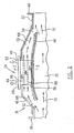
- Figure 1 illustrates a turbofan bypass gas turbine engine which includes a housing 10, a core casing 13, a low pressure spool assembly seen generally at 12 which includes a shaft 15 interconnecting a fan assembly 14, a low pressure compressor 16 and a low pressure turbine assembly 18, and a high pressure spool assembly seen generally at 20 which includes a shaft 25 interconnecting a high pressure compressor assembly 22 and a high pressure turbine assembly 24.
- the core casing 13 surrounds the low and high pressure spool assemblies 12 and 20 to define a main fluid path (not indicated) through the engine.
- a combustion section 26 having a combustor 28 therein.
- An annular bypass duct 30 is defined between an inner bypass duct wall, formed for example by the core casing 13, and an outer bypass duct wall 32 formed by an outer bypass duct casing located within the housing 10.
- a stream of bypass air which is compressed by the fan assembly 14, is directed through the annular bypass duct 30 and is discharged therefrom to produce thrust.
- the engine has a lubricating system (not indicated) including a pump (not shown) and a heat exchanger 34 positioned within the annular bypass duct 30, according to one embodiment of the present invention.
- the heat exchanger 34 is connected in fluid communication with a fluid circuit (not shown) such as a lubricating system of the engine, to allow relatively hot oil to flow therethrough and be thereby cooled by a fast moving stream of bypass air passing through the annular bypass duct 30.
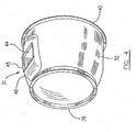
- a section of the outer bypass duct wall 32 is defined by an outer bypass duct casing or annular body 31, preferably made of sheet metal or other suitable material.
- the front end of the annular body 31 has an opening with a radially extending flange 36 to be connected to an intermediate casing 38 (see Figure 1) which in turn is connected to a fan casing 39.
- the rear end of the annular body 31 has a radially outwardly extending flange 40 to be connected with an engine exhaust duct 42 (see Figure 1).
- the annular body 31 has an open area 44, for example in a rectangular shape, as shown in Figure 3.
- the open area 44 is preferably defined in a portion 46 of the outer annular wall 32 of the bypass duct 30 which is radially outwardly protuberant relative to the remaining portion of the annular body 31, for reasons discussed further below.
- the protuberant portion 46 may be integrated with the remaining portion of the outer annular wall 32. However, in this embodiment, the protuberant portion 46 is fabricated in a process separate from the manufacturing of the remaining portion of the annular outer wall 32, and is then attached, for example by welding, to the remaining portion of the outer annular wall 32.
- the protuberant portion 46 of the outer annular wall 32 preferably includes outwardly extending flanges 45 along the edge of the rectangular open area 44. Preferably, the protuberant portion 46 flares outwardly around the rectangular open area 44 to provide the flanges 45.
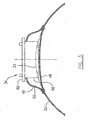
- a fluid divider 48 which is preferably made of a metal plate pressed in a smoothly curved aerodynamic configuration as shown in Figure 2, is affixed, for example by welding, to the inner side of the outer annular wall 32 of the bypass duct 30, preferably in a location adjacent the protuberant portion 46.
- the fluid divider 48 in combination with the outer annular wall 32 of the bypass duct 30, particularly the protuberant portion 46 thereof, thereby forms a flow sub-passage 50 within the bypass duct 32.
- the flow sub-passage 50 defines an upstream open end 52 and a downstream open end 54 and is accessible from outside of the annular body 31 (the outer bypass duct casing) through the open area 44.
- the fluid divider 48, together with protuberant portion 46 provides an inlet scoop function, projecting partially into the bypass flow, and an outlet venturi function to develop the required pressure differential needed to drive air through the cooler.
- the protuberant portion 46 forms an additional space which is added to the annular bypass duct 30 to receive the heat exchanger 34. Therefore, the heat exchanger 34 is almost buried within the additional space to not substantially intrude into the annular bypass duct 30.
- the fluid divider 48 is smoothly curved in a configuration such that the slightly inwardly extending front and rear portions of the fluid divider 48, in combination with the protuberant portion 46, form the upstream and downstream open ends 52, 54 within the annular bypass duct 30 near the outer annular wall 32 (see Figure 2), while the middle portion of the fluid divider 48 is shaped and positioned preferably in a close relationship with an outer duct diameter 33 (see Figure 3).
- the heat exchanger 34 can be selected from a variety of configurations.
- coil tubes (not shown) are arranged in a sinusoidal pattern to define a fluid passage which is exposed to and is thus cooled by air flow passing through spaces between the coil tubes.
- the heat exchanger 34 is configured with a plurality of tubes 56, preferably made of sheet metal or other suitable material. Metal is preferred in order to provide good heat transfer properties.
- Each tube 56 extends transversely and reverses at opposite sides to form a layer preferably in a rectangular configuration.
- Each layer (3 layers in this embodiment) of the tubes 56 are in fluid communication by vertical tubes 57 at the corners of the rectangular configuration.
- the rectangular configuration is sized to be received within the flow sub-passage 50 through the open area 44 of the outer annular wall 32 of the bypass duct 30.
- a plurality of corrugated metal sheets 59 and metal fins are preferably placed between and contact the layers of tubes 56 to increase heat exchange surfaces.
- the corrugated metal sheets 59 thus define a plurality of air passages 58 extending through the heat exchanger 34.
- An over-sized cover plate 60 is preferably attached to the top layer of tubes 56.
- the cover plate 60 includes a fluid inlet 62 and a fluid outlet 64 which are in fluid communication with the tubes 56, thereby defining at least one fluid passage 66 through the heat exchanger 34, as illustrated by the hollow arrows in Figure 2.
- the inlet and outlet are arranged such that flow through the fluid passage 66 is in the opposite direction to the bypass flow through the device, to improve heat transfer.
- a small tank (shown in Figure 5 but not indicated) is preferably attached to the heat exchanger 34 at each of the opposite sides thereof in fluid communication with and as a part of the fluid passage 66.
- the inlet and outlet 62, 64 extend out of the outer side of the cover plate 60 for connection to a fluid circuit, for example the lubricating system of the engine.
- the cover plate 60 is shaped and sized so as mate with the outwardly extending flanges 45 on the edge of the open area 44, to seal the open area 44.
- a plurality of mounting holes are preferably provided in the cover plate 60 to permit mounting screws or bolts (not shown) to pass therethrough in order to mount the cover plate 60, together with the heat exchanger 34, to the outer annular wall 32 of the bypass duct 30.
- the cover plate 60 functions not only as a cover for the open area 44 of the outer annular wall 32 of the bypass duct 30, but also as a base support of the heat exchanger 34 when placed in position within the bypass duct 30.
- the heat exchanger 34 can be installed within the bypass duct 30 and positioned in the flow sub-passage 50 with the following installation procedure. From outside the bypass duct, the heat exchanger 34 is inserted into the open area 44 until the open area 44 is covered by the cover plate 60.
- the cover plate 60 is securely connected to the annular body 31 by the mounting screws or bolts, and thus securely supports the heat exchanger 34 in position within sub-passage 50.
- the flow inlet and outlet 62, 64 can be connected to the suitable fluid circuit of the engine.
- the simplicity of installation and removal of the heat exchanger 34 provided by positioning the heat exchanger on the outer bypass duct and permitting it to be installed from outside the outer bypass, reduces maintenance and inspection time and thus operation costs thereof because further disassembly of the engine and/or complicated tools are not required.
- the device thus may be a line replaceable unit (LRU) which can be removed and/or placed without engine removal from its operational setting (e.g. "on the wing").
- LRU line replaceable unit
- bypass air flow indicated by arrows 68 is divided from the main bypass air flow 70 at the upstream open end 52 of the flow sub-passage 50 because the upstream open end 52 is located within the annular bypass duct 30, performing a "scoop" function.
- the portion of bypass air flow 68 is directed along the flow sub-passage 50 and passes through the heat exchanger 34 to be discharged from the downstream open end 54 into the main bypass air flow 70 through a venturi section, as described further below.
- the engine fluid such as oil for lubrication is directed to flow through the fluid passage 66 defined within the container 56, from the inlet 62 to the outlet 64. Therefore, the relatively hot oil contacts the inner surface of the container walls and surrounds the air tubes 58.
- bypass air flow 68 passing through the heat exchanger 34 which is much cooler than the hot oil, passes along the side walls of the container 56 and through the air tubes 58, thereby causing heat exchange between the hot oil and the rapid bypass air flow 68, through the metal walls of the container 56 and the plurality of metal air tubes 58. Heat is also added to the diverted air, thereby reducing the already negligible performance loss introduced by the present device to the overall gas turbine system.
- the portion of bypass air flow 68 is discharged back into the main bypass air flow 70.
- the shape of the sub-passage 50, as defined by the protuberant portion 46, together with the velocity of the main bypass air flow 70, creates a venturi effect at the downstream open end 54 of the flow sub-passage 50 to cause a local low pressure area such that the pressure differential between the upstream open end 52 and the downstream open end 54 of the flow sub-passage 50 is increased.
- This increased pressure differential over the flow sub-passage 50 facilitates air flow through sub-passage 50, and thereby improves the heat exchange between the portion of the bypass air flow 68 and the heat exchanger 34 (and thus the hot fluid passing therethrough).
- the heat exchanger 34 is almost buried in the additional space defined by the protuberant portion 46 and does not substantially intrude into the annular bypass duct 30, and more particularly, the middle section of the fluid divider 48 is in a close relationship with the outer diameter 33 of the bypass duct 30.
- the bypass duct main flow 70 is not significantly interfered with by the installation of the cooling apparatus of this invention.
- a further advantage of this invention is lack of ducting which additionally reduces size, weight and pressure loss of the engine.
- the heat exchanger can be otherwise configured as an air cooled fluid cooler of any suitable type, and need not be the above-described radiator type and the illustrated container type.
- the cooling apparatus of the present invention can be used as an air cooled oil cooler of a gas turbine engine, but also can be used to cool other fluids such as fuel or hydraulic fluids of the gas turbine engine.
- the cooling apparatus of the present invention can be positioned within the bypass duct in combination with an inner annular wall of the bypass duct.
- a cooling apparatus according to the above teachings may be positioned in any suitable configuration so as to communicate with the bypass flow, such as within a strut, fairing, etc. Still other modifications will be apparent to those skilled in the art in light of a review of this disclosure, and such modifications may fall within the scope of the invention which is defined by the appended claims.
Abstract
Description
- The invention relates generally to gas turbine engines and more particularly, to an improved cooling apparatus for cooling of a fluid used in a turbofan bypass gas turbine engine.
- Lubricating oil used in aircraft gas turbine engines must be cooled. Without proper cooling, poor cooling and/or poor lubrication of gears and bearings result, which may cause problems for engine operation. In addition to employing conventional radiator-type oil coolers, the prior art also describes directing oil through inlet guide vanes or support struts to achieve a cooling benefit from air ingested by the engine. The cooling of engine fluid is also achieved by directing the fluid flowing directly along a surface defining a periphery of a bypass duct of a turbofan bypass gas turbine engine, to thereby permit heat exchange between the fluid and bypass air passing through the bypass duct. However, efforts have been made to further improve the cooling of lubricating fluids of gas turbine engines.
- Accordingly, there is a need to provide an improved cooling apparatus for use in gas turbine engines, particularly in turbofan bypass gas turbine engines.
- It is therefore an object of this invention to provide a cooling apparatus for cooling of fluid used in a gas turbine engine.
- In one aspect, the present invention provides a cooling apparatus for cooling a fluid in a bypass gas turbine engine, which comprises a heat exchanger defining a fluid passage, the heat exchanger being disposed within a bypass duct and being exposed to a bypass air flow; and a flow divider affixed to an annular wall of the bypass duct, in combination with the wall of the bypass duct forming a sub-passage for accommodating the heat exchanger, the sub-passage defining an open upstream end and an open downstream end to direct a portion of the bypass air flow to pass therethrough.
- In another aspect, the present invention provides a gas turbine engine which comprises a core engine; a bypass duct surrounding the core engine and adapted to direct a bypass air flow through the bypass duct; a heat exchanger defining a fluid passage, the heat exchanger being disposed within the bypass duct and being exposed to the bypass air flow; and means for increasing a local pressure differential of the bypass air flow between upstream and downstream locations with respect to the heat exchanger in order to facilitate heat exchange between the heat exchanger and the air flow.
- In another aspect, the present invention provides a method of installing a fluid cooling apparatus in a gas turbine engine, which comprises: 1) placing a heat exchanger into a bypass duct through an open area of an outer annular wall of the bypass duct and positioning the heat exchanger in a sub-passage defined within the bypass duct; and 2) closing the open area of the outer wall of the bypass duct, the heat exchanger being connectable to a fluid circuit of the engine.
- Further details of these and other aspects of the present invention will be apparent from the detailed description and figures included below.
- Reference is now made to the accompanying figures depicting aspects of the present invention, in which:
- Figure 1 is a schematic cross-sectional view of a turbofan bypass gas turbine engine, showing an exemplary application of a fluid cooling apparatus;
- Figure 2 is a partial cross-sectional view of the fluid cooling apparatus of Figure 1;
- Figure 3 is a partial cross-sectional view taken along line 3-3 of Figure 2, showing a traverse section of the sub-passage defined by the fluid divider;
- Figure 4 is an isometric view of the outer bypass casing of the turbofan engine of Figure 1; and
- Figure 5 is an isometric view of an exemplary embodiment of a heat exchanger of the fluid cooling apparatus of Figure 1.
- Figure 1 illustrates a turbofan bypass gas turbine engine which includes a
housing 10, acore casing 13, a low pressure spool assembly seen generally at 12 which includes a shaft 15 interconnecting afan assembly 14, alow pressure compressor 16 and a lowpressure turbine assembly 18, and a high pressure spool assembly seen generally at 20 which includes ashaft 25 interconnecting a highpressure compressor assembly 22 and a highpressure turbine assembly 24. Thecore casing 13 surrounds the low and highpressure spool assemblies 12 and 20 to define a main fluid path (not indicated) through the engine. In the main fluid path there is provided acombustion section 26 having acombustor 28 therein. Anannular bypass duct 30 is defined between an inner bypass duct wall, formed for example by thecore casing 13, and an outerbypass duct wall 32 formed by an outer bypass duct casing located within thehousing 10. A stream of bypass air which is compressed by thefan assembly 14, is directed through theannular bypass duct 30 and is discharged therefrom to produce thrust. - The engine has a lubricating system (not indicated) including a pump (not shown) and a
heat exchanger 34 positioned within theannular bypass duct 30, according to one embodiment of the present invention. Theheat exchanger 34 is connected in fluid communication with a fluid circuit (not shown) such as a lubricating system of the engine, to allow relatively hot oil to flow therethrough and be thereby cooled by a fast moving stream of bypass air passing through theannular bypass duct 30. - Referring to Figures 1-5 and in accordance with an embodiment of the present invention, a section of the outer
bypass duct wall 32 is defined by an outer bypass duct casing orannular body 31, preferably made of sheet metal or other suitable material. The front end of theannular body 31 has an opening with a radially extendingflange 36 to be connected to an intermediate casing 38 (see Figure 1) which in turn is connected to afan casing 39. The rear end of theannular body 31 has a radially outwardly extendingflange 40 to be connected with an engine exhaust duct 42 (see Figure 1). - The
annular body 31 has anopen area 44, for example in a rectangular shape, as shown in Figure 3. Theopen area 44 is preferably defined in aportion 46 of the outerannular wall 32 of thebypass duct 30 which is radially outwardly protuberant relative to the remaining portion of theannular body 31, for reasons discussed further below. Theprotuberant portion 46 may be integrated with the remaining portion of the outerannular wall 32. However, in this embodiment, theprotuberant portion 46 is fabricated in a process separate from the manufacturing of the remaining portion of the annularouter wall 32, and is then attached, for example by welding, to the remaining portion of the outerannular wall 32. Theprotuberant portion 46 of the outerannular wall 32 preferably includes outwardly extendingflanges 45 along the edge of the rectangularopen area 44. Preferably, theprotuberant portion 46 flares outwardly around the rectangularopen area 44 to provide theflanges 45. - A
fluid divider 48 which is preferably made of a metal plate pressed in a smoothly curved aerodynamic configuration as shown in Figure 2, is affixed, for example by welding, to the inner side of the outerannular wall 32 of thebypass duct 30, preferably in a location adjacent theprotuberant portion 46. The fluid divider 48, in combination with the outerannular wall 32 of thebypass duct 30, particularly theprotuberant portion 46 thereof, thereby forms aflow sub-passage 50 within thebypass duct 32. Theflow sub-passage 50 defines an upstreamopen end 52 and a downstreamopen end 54 and is accessible from outside of the annular body 31 (the outer bypass duct casing) through theopen area 44. Thefluid divider 48, together withprotuberant portion 46, provides an inlet scoop function, projecting partially into the bypass flow, and an outlet venturi function to develop the required pressure differential needed to drive air through the cooler. - The
protuberant portion 46 forms an additional space which is added to theannular bypass duct 30 to receive theheat exchanger 34. Therefore, theheat exchanger 34 is almost buried within the additional space to not substantially intrude into theannular bypass duct 30. Thefluid divider 48 is smoothly curved in a configuration such that the slightly inwardly extending front and rear portions of thefluid divider 48, in combination with theprotuberant portion 46, form the upstream and downstreamopen ends annular bypass duct 30 near the outer annular wall 32 (see Figure 2), while the middle portion of thefluid divider 48 is shaped and positioned preferably in a close relationship with an outer duct diameter 33 (see Figure 3). - The
heat exchanger 34 can be selected from a variety of configurations. For example, coil tubes (not shown) are arranged in a sinusoidal pattern to define a fluid passage which is exposed to and is thus cooled by air flow passing through spaces between the coil tubes. Theheat exchanger 34, however, according to this embodiment and illustrated in Figures 2-5, is configured with a plurality oftubes 56, preferably made of sheet metal or other suitable material. Metal is preferred in order to provide good heat transfer properties. Eachtube 56 extends transversely and reverses at opposite sides to form a layer preferably in a rectangular configuration. Each layer (3 layers in this embodiment) of thetubes 56 are in fluid communication byvertical tubes 57 at the corners of the rectangular configuration. The rectangular configuration is sized to be received within theflow sub-passage 50 through theopen area 44 of the outerannular wall 32 of thebypass duct 30. A plurality ofcorrugated metal sheets 59 and metal fins (not shown) are preferably placed between and contact the layers oftubes 56 to increase heat exchange surfaces. Thecorrugated metal sheets 59 thus define a plurality ofair passages 58 extending through theheat exchanger 34. - An over-sized
cover plate 60 is preferably attached to the top layer oftubes 56. Thecover plate 60 includes afluid inlet 62 and afluid outlet 64 which are in fluid communication with thetubes 56, thereby defining at least onefluid passage 66 through theheat exchanger 34, as illustrated by the hollow arrows in Figure 2. Preferably, the inlet and outlet are arranged such that flow through thefluid passage 66 is in the opposite direction to the bypass flow through the device, to improve heat transfer. A small tank (shown in Figure 5 but not indicated) is preferably attached to theheat exchanger 34 at each of the opposite sides thereof in fluid communication with and as a part of thefluid passage 66. - The inlet and
outlet cover plate 60 for connection to a fluid circuit, for example the lubricating system of the engine. Thecover plate 60 is shaped and sized so as mate with the outwardly extendingflanges 45 on the edge of theopen area 44, to seal theopen area 44. A plurality of mounting holes (not indicated) are preferably provided in thecover plate 60 to permit mounting screws or bolts (not shown) to pass therethrough in order to mount thecover plate 60, together with theheat exchanger 34, to the outerannular wall 32 of thebypass duct 30. Thecover plate 60 functions not only as a cover for theopen area 44 of the outerannular wall 32 of thebypass duct 30, but also as a base support of theheat exchanger 34 when placed in position within thebypass duct 30. - The
heat exchanger 34 can be installed within thebypass duct 30 and positioned in theflow sub-passage 50 with the following installation procedure. From outside the bypass duct, theheat exchanger 34 is inserted into theopen area 44 until theopen area 44 is covered by thecover plate 60. Thecover plate 60 is securely connected to theannular body 31 by the mounting screws or bolts, and thus securely supports theheat exchanger 34 in position withinsub-passage 50. Preferably after theheat exchanger 34 is securely supported in position, the flow inlet andoutlet heat exchanger 34 provided by positioning the heat exchanger on the outer bypass duct and permitting it to be installed from outside the outer bypass, reduces maintenance and inspection time and thus operation costs thereof because further disassembly of the engine and/or complicated tools are not required. The device thus may be a line replaceable unit (LRU) which can be removed and/or placed without engine removal from its operational setting (e.g. "on the wing"). - During engine operation, a portion of bypass air flow indicated by
arrows 68 is divided from the mainbypass air flow 70 at the upstreamopen end 52 of theflow sub-passage 50 because the upstreamopen end 52 is located within theannular bypass duct 30, performing a "scoop" function. The portion ofbypass air flow 68 is directed along theflow sub-passage 50 and passes through theheat exchanger 34 to be discharged from the downstreamopen end 54 into the mainbypass air flow 70 through a venturi section, as described further below. The engine fluid such as oil for lubrication is directed to flow through thefluid passage 66 defined within thecontainer 56, from theinlet 62 to theoutlet 64. Therefore, the relatively hot oil contacts the inner surface of the container walls and surrounds theair tubes 58. Meanwhile, the portion ofbypass air flow 68 passing through theheat exchanger 34, which is much cooler than the hot oil, passes along the side walls of thecontainer 56 and through theair tubes 58, thereby causing heat exchange between the hot oil and the rapidbypass air flow 68, through the metal walls of thecontainer 56 and the plurality ofmetal air tubes 58. Heat is also added to the diverted air, thereby reducing the already negligible performance loss introduced by the present device to the overall gas turbine system. - At the downstream
open end 56 of theflow sub-passage 50, the portion ofbypass air flow 68 is discharged back into the mainbypass air flow 70. The shape of the sub-passage 50, as defined by theprotuberant portion 46, together with the velocity of the mainbypass air flow 70, creates a venturi effect at the downstreamopen end 54 of theflow sub-passage 50 to cause a local low pressure area such that the pressure differential between the upstreamopen end 52 and the downstreamopen end 54 of theflow sub-passage 50 is increased. This increased pressure differential over theflow sub-passage 50 facilitates air flow throughsub-passage 50, and thereby improves the heat exchange between the portion of thebypass air flow 68 and the heat exchanger 34 (and thus the hot fluid passing therethrough). - As described, the
heat exchanger 34 is almost buried in the additional space defined by theprotuberant portion 46 and does not substantially intrude into theannular bypass duct 30, and more particularly, the middle section of thefluid divider 48 is in a close relationship with the outer diameter 33 of thebypass duct 30. The bypass ductmain flow 70 is not significantly interfered with by the installation of the cooling apparatus of this invention. - A further advantage of this invention is lack of ducting which additionally reduces size, weight and pressure loss of the engine.
- The above description is meant to be exemplary only, and one skilled in the art will recognize that changes may be made to the embodiments described without departure from the scope of the invention disclosed. For example, the heat exchanger can be otherwise configured as an air cooled fluid cooler of any suitable type, and need not be the above-described radiator type and the illustrated container type. The cooling apparatus of the present invention can be used as an air cooled oil cooler of a gas turbine engine, but also can be used to cool other fluids such as fuel or hydraulic fluids of the gas turbine engine. Although the flow sub-passage is defined between a flow divider and a portion of the outer annular wall of the bypass duct, particularly for convenience of installation, the cooling apparatus of the present invention can be positioned within the bypass duct in combination with an inner annular wall of the bypass duct. Alternately, a cooling apparatus according to the above teachings may be positioned in any suitable configuration so as to communicate with the bypass flow, such as within a strut, fairing, etc. Still other modifications will be apparent to those skilled in the art in light of a review of this disclosure, and such modifications may fall within the scope of the invention which is defined by the appended claims.
Claims (15)
- A cooling apparatus for cooling a fluid in a bypass gas turbine engine, the apparatus comprising:a heat exchanger (34) defining a fluid passage (66), the heat exchanger being disposed within a bypass duct (30) and being exposed to a bypass air flow; anda flow divider (48) affixed to an annular wall (32) of the bypass duct, in combination with the wall of the bypass duct forming a sub-passage (50) for accommodating the heat exchanger, the sub-passage defining an open upstream end (52) and an open downstream end (54) to direct a portion of the bypass air flow to pass therethrough.
- The apparatus as defined in claim 1 wherein the annular wall (32) of the bypass duct, in combination with the flow divider to define the sub-passage, is an outer wall of the bypass wall having an open area (44) therein to allow the heat exchanger to be placed therethrough into position within the bypass duct.
- The apparatus as defined in claim 2 wherein the heat exchanger comprises a cover plate (60) affixed therewith, the cover plate being removeably attached to the outer wall of the bypass duct in order to close the open area thereof and support the heat exchanger in position.
- The apparatus as defined in claim 3 wherein the heat exchanger comprises an inlet (62) and an outlet (64) in fluid communication with the fluid passage defined therein, the inlet and outlet extending out of an outer side of the cover plate.
- The apparatus as defined in claim 2, 3 or 4 wherein the outer wall of the bypass duct comprises a portion (46) thereof adjacent the open area, which is radially protuberant to form an additional space in the sub-passage for accommodating the heat exchanger.
- The apparatus as defined in any preceding claim wherein the heat exchanger defines an air passage (58) to allow heat exchange between air flowing therethrough and a fluid flowing through the fluid passage (66).
- A gas turbine engine comprising:a core engine (13);a bypass duct (30) surrounding the core engine and adapted to direct a bypass air flow through the bypass duct;a heat exchanger (34) defining a fluid passage (66), the heat exchanger being disposed within the bypass duct and being exposed to the bypass air flow; andmeans (48) for increasing a local pressure differential of the bypass air flow between upstream and downstream locations with respect to the heat exchanger in order to facilitate heat exchange between the heat exchanger and the air flow.
- The gas turbine engine as defined in claim 7 wherein the means comprise a flow divider (48) affixed to an annular wall (32) of the bypass duct, in combination with the wall of the bypass duct to form a sub-passage for accommodating the heat exchanger (34), the sub-passage defining an open upstream end (52) and an open downstream end (54) to direct a portion of the bypass air flow to pass therethrough.
- The gas turbine engine as defined in claim 8 wherein the open downstream end (54) of the sub-passage is located within the bypass duct (30) to form a venturi throat with respect to a main air flow passing through the bypass duct but bypassing the sub-passage.
- The gas turbine engine as defined in claim 7, 8 or 9 wherein an outer annular wall (32) of the bypass duct comprises a portion (46) thereof radially protuberant to form an additional space within the bypass duct in order to accommodate the heat exchanger (34) therein.
- The gas turbine engine as defined in claim 10 wherein the protuberant portion (46) of the outer annular wall of the bypass duct defines an open area (44) therein for placing the heat exchanger therethrough into the bypass duct.
- The gas turbine engine as defined in claim 11 wherein the heat exchanger comprises a cover plate (60) affixed therewith, the cover plate being removeably attached to the outer annular wall of the bypass duct in order to close the open area thereof and support the heat exchanger in position.
- A method of installing a fluid cooling apparatus in a gas turbine engine, the method comprising:1) placing a heat exchanger into a bypass duct through an open area of an outer annular wall of the bypass duct and positioning the heat exchanger in a sub-passage defined within the bypass duct; and2) closing the open area of the outer wall of the bypass duct, the heat exchanger being connectable to a fluid circuit of the engine.
- The method as defined in claim 13 wherein the closing step is practised by attaching a cover plate affixed on the heat exchanger to the outer annular wall of the bypass duct in order to close the open area while supporting the heat exchanger in position.
- The method as defined in claim 14 comprising a step of connecting the heat exchanger to the fluid circuit of the engine through an inlet and an outlet of the heat exchanger, the inlet and outlet extending out of an outer side of the cover plate.
Applications Claiming Priority (1)
| Application Number | Priority Date | Filing Date | Title |
|---|---|---|---|
| US11/511,419 US7861512B2 (en) | 2006-08-29 | 2006-08-29 | Turbofan bypass duct air cooled fluid cooler installation |
Publications (3)
| Publication Number | Publication Date |
|---|---|
| EP1898069A2 true EP1898069A2 (en) | 2008-03-12 |
| EP1898069A3 EP1898069A3 (en) | 2011-04-27 |
| EP1898069B1 EP1898069B1 (en) | 2015-01-21 |
Family
ID=38690230
Family Applications (1)
| Application Number | Title | Priority Date | Filing Date |
|---|---|---|---|
| EP07253392.0A Active EP1898069B1 (en) | 2006-08-29 | 2007-08-29 | Turbofan bypass duct air cooled fluid cooler installation |
Country Status (4)
| Country | Link |
|---|---|
| US (1) | US7861512B2 (en) |
| EP (1) | EP1898069B1 (en) |
| CA (1) | CA2661707C (en) |
| WO (1) | WO2008025136A1 (en) |
Cited By (13)
| Publication number | Priority date | Publication date | Assignee | Title |
|---|---|---|---|---|
| EP1916399A2 (en) * | 2006-10-19 | 2008-04-30 | General Electric Company | Heat exchanger assembly for a gas turbine engine |
| EP2519723A2 (en) * | 2009-12-31 | 2012-11-07 | Rolls-Royce North American Technologies, Inc. | Gas turbine engine and heat exchange system |
| EP2336504A3 (en) * | 2009-12-09 | 2014-08-20 | Rolls-Royce plc | Oil cooler |
| WO2014137451A1 (en) * | 2013-03-04 | 2014-09-12 | Rolls-Royce North American Technologies, Inc. | Ram air thermal management system for an aircraft engine |
| WO2014200587A3 (en) * | 2013-01-21 | 2015-03-05 | United Technologies Corporation | Air oil cooler airflow augmentation system |
| FR3015569A1 (en) * | 2013-12-19 | 2015-06-26 | Snecma | CARTER FOR A PROPULSIVE ASSEMBLY |
| US10393147B2 (en) | 2015-07-23 | 2019-08-27 | Unison Industries, Llc | Fan casing assemblies and method of mounting a cooler to a fan casing |
| CN110259581A (en) * | 2019-05-05 | 2019-09-20 | 南京航空航天大学 | A kind of by-pass air duct double-work medium heat exchanger using air and fuel oil |
| EP3696389A1 (en) * | 2019-02-18 | 2020-08-19 | Safran Aero Boosters SA | Air-oil heat exchanger |
| EP3745833A1 (en) * | 2019-05-31 | 2020-12-02 | Hamilton Sundstrand Corporation | Aircraft power electronic unit and method of cooling |
| WO2022074339A1 (en) * | 2020-10-08 | 2022-04-14 | Safran | Countercurrent heat exchanger for a turbomachine, turbomachine, and method for manufacturing the exchanger |
| US11466700B2 (en) | 2017-02-28 | 2022-10-11 | Unison Industries, Llc | Fan casing and mount bracket for oil cooler |
| FR3132328A1 (en) * | 2022-02-01 | 2023-08-04 | Safran | HEAT EXCHANGER EQUIPPED WITH AN AIR DIFFUSION SYSTEM AND CORRESPONDING TURBOMACHINE |
Families Citing this family (67)
| Publication number | Priority date | Publication date | Assignee | Title |
|---|---|---|---|---|
| US8127828B2 (en) * | 2006-03-17 | 2012-03-06 | United Technologies Corporation | Air-oil heat exchanger |
| US20080053060A1 (en) * | 2006-08-29 | 2008-03-06 | Pratt & Whitney Canada Corp. | Bypass lip seal |
| US8516791B2 (en) * | 2007-07-30 | 2013-08-27 | General Electric Company | Methods and apparatus for mixing fluid in turbine engines |
| US8438835B2 (en) * | 2007-07-30 | 2013-05-14 | General Electric Company | Methods and apparatus for mixing fluid in turbine engines |
| US8266889B2 (en) * | 2008-08-25 | 2012-09-18 | General Electric Company | Gas turbine engine fan bleed heat exchanger system |
| US8627667B2 (en) * | 2008-12-29 | 2014-01-14 | Roll-Royce Corporation | Gas turbine engine duct having a coupled fluid volume |
| US8245494B2 (en) * | 2009-02-12 | 2012-08-21 | Hamilton Sundstrand Corporation | Gas turbine engine with eductor and eductor flow distribution shield |
| WO2011005858A2 (en) * | 2009-07-09 | 2011-01-13 | Frontline Aerospace, Inc. | Compressor cooling for turbine engines |
| DE102009055879A1 (en) * | 2009-11-26 | 2011-06-01 | Rolls-Royce Deutschland Ltd & Co Kg | Aircraft deicing device and engine nacelle of an aircraft gas turbine with deicing device |
| US8756910B2 (en) | 2009-12-31 | 2014-06-24 | Rolls-Royce North American Technologies, Inc. | Gas turbine engine and cooling system |
| GB2478934B (en) * | 2010-03-24 | 2012-06-13 | Rolls Royce Plc | Fuel heat management system |
| WO2012012912A1 (en) * | 2010-07-29 | 2012-02-02 | General Electric Company | Reconfigurable heat transfer system for gas turbine inlet |
| US9109464B2 (en) | 2011-08-31 | 2015-08-18 | United Technologies Corporation | Distributed lubrication system |
| US9045998B2 (en) | 2011-12-12 | 2015-06-02 | Honeywell International Inc. | System for directing air flow to a plurality of plena |
| US9109514B2 (en) | 2012-01-10 | 2015-08-18 | Hamilton Sundstrand Corporation | Air recovery system for precooler heat-exchanger |
| US9243563B2 (en) | 2012-01-25 | 2016-01-26 | Honeywell International Inc. | Gas turbine engine in-board cooled cooling air system |
| US9200570B2 (en) * | 2012-02-24 | 2015-12-01 | Pratt & Whitney Canada Corp. | Air-cooled oil cooler for turbofan engine |
| US9267390B2 (en) | 2012-03-22 | 2016-02-23 | Honeywell International Inc. | Bi-metallic actuator for selectively controlling air flow between plena in a gas turbine engine |
| US9388739B2 (en) | 2012-05-02 | 2016-07-12 | Pratt & Whitney Canada Corp. | Air cooler system for gas turbine engines |
| FR2993610B1 (en) * | 2012-07-19 | 2014-07-11 | Snecma | COOLING THE OIL CIRCUIT OF A TURBOMACHINE |
| US20140216056A1 (en) * | 2012-09-28 | 2014-08-07 | United Technologies Corporation | Heat exchange module for a turbine engine |
| US9714610B2 (en) * | 2012-10-04 | 2017-07-25 | United Technologies Corporation | Low profile compressor bleed air-oil coolers |
| US9458764B2 (en) | 2012-11-26 | 2016-10-04 | Pratt & Whitney Canada Corp. | Air cooled air cooler for gas turbine engine air system |
| US8776835B2 (en) | 2012-12-05 | 2014-07-15 | Hamilton Sundstrand Corporation | Fluid duct with improved connecting bead |
| EP2971739B1 (en) | 2013-03-14 | 2020-03-18 | Rolls-Royce North American Technologies, Inc. | Gas turbine engine flow duct having two rows of integrated heat exchangers |
| US10352191B2 (en) * | 2013-03-15 | 2019-07-16 | United Technologies Corporation | Gas turbine engine with air-oil cooler oil tank |
| WO2014201311A1 (en) | 2013-06-14 | 2014-12-18 | United Technologies Corporation | Curved plate/fin heat exchanger |
| US9512780B2 (en) | 2013-07-31 | 2016-12-06 | General Electric Company | Heat transfer assembly and methods of assembling the same |
| US9677474B2 (en) | 2013-11-18 | 2017-06-13 | Unison Industries, Llc | Surface cooler support mechanism |
| FR3015573B1 (en) * | 2013-12-19 | 2015-12-11 | Snecma | AIRCRAFT TURBOMACHINE COMPRISING A HEAT EXCHANGER OF THE PRE-COOLING TYPE |
| US10006369B2 (en) | 2014-06-30 | 2018-06-26 | General Electric Company | Method and system for radial tubular duct heat exchangers |
| US9777963B2 (en) | 2014-06-30 | 2017-10-03 | General Electric Company | Method and system for radial tubular heat exchangers |
| US9341119B2 (en) * | 2014-07-03 | 2016-05-17 | Hamilton Sundstrand Corporation | Cooling air system for aircraft turbine engine |
| US20160017810A1 (en) * | 2014-07-21 | 2016-01-21 | United Technologies Corporation | Acoustic liner heat exchanger |
| US9932892B2 (en) | 2015-02-20 | 2018-04-03 | Pratt & Whitney Canada Corp. | Compound engine assembly with coaxial compressor and offset turbine section |
| US9797297B2 (en) | 2015-02-20 | 2017-10-24 | Pratt & Whitney Canada Corp. | Compound engine assembly with common inlet |
| US9879591B2 (en) | 2015-02-20 | 2018-01-30 | Pratt & Whitney Canada Corp. | Engine intake assembly with selector valve |
| US9896998B2 (en) * | 2015-02-20 | 2018-02-20 | Pratt & Whitney Canada Corp. | Compound engine assembly with modulated flow |
| US10100730B2 (en) | 2015-03-11 | 2018-10-16 | Pratt & Whitney Canada Corp. | Secondary air system with venturi |
| US9835380B2 (en) | 2015-03-13 | 2017-12-05 | General Electric Company | Tube in cross-flow conduit heat exchanger |
| US9982630B2 (en) | 2015-05-26 | 2018-05-29 | Pratt & Whitney Canada Corp. | Turbofan bypass air cooled oil cooler fairings |
| US20170009118A1 (en) * | 2015-07-10 | 2017-01-12 | General Electric Company | Method and apparatus for generating latent heat at low temperatures using exothermic salt crystallization |
| US10436114B2 (en) | 2015-08-26 | 2019-10-08 | Pratt & Whitney Canada Corp. | Combustor cooling system |
| US10184400B2 (en) * | 2016-01-08 | 2019-01-22 | General Electric Company | Methods of cooling a fluid using an annular heat exchanger |
| US10151247B2 (en) * | 2016-03-18 | 2018-12-11 | United Technologies Corporation | Heat exchanger suspension system with pipe-to-linkage spring rate ratio |
| US10378835B2 (en) | 2016-03-25 | 2019-08-13 | Unison Industries, Llc | Heat exchanger with non-orthogonal perforations |
| US10443436B2 (en) * | 2016-07-01 | 2019-10-15 | General Electric Company | Modular annular heat exchanger |
| FR3067404B1 (en) * | 2017-06-12 | 2019-11-15 | Safran Aircraft Engines | THERMAL EXCHANGER EQUIPPED WITH A UPSTREAM COVERAGE FOR REDUCING FLUID FLOW DISTURBANCE IN A TURBOMACHINE |
| US10527012B2 (en) * | 2017-06-29 | 2020-01-07 | Pratt & Whitney Canada Corp. | Engine assembly with engine and cooler compartments |
| GB201718796D0 (en) | 2017-11-14 | 2017-12-27 | Rolls Royce Plc | Gas turbine engine having an air-oil heat exchanger |
| CA3064652A1 (en) | 2018-12-07 | 2020-06-07 | Pratt & Whitney Canada Corp. | Static take-off port |
| FR3096444B1 (en) | 2019-05-20 | 2021-05-07 | Safran | OPTIMIZED HEAT EXCHANGE SYSTEM |
| FR3096409B1 (en) | 2019-05-20 | 2021-04-30 | Safran | OPTIMIZED HEAT EXCHANGE SYSTEM |
| WO2020249599A1 (en) * | 2019-06-14 | 2020-12-17 | Rolls-Royce Deutschland Ltd & Co Kg | Gas turbine engine and heat management system for cooling oil in an oil system of a gas turbine engine |
| US11448132B2 (en) | 2020-01-03 | 2022-09-20 | Raytheon Technologies Corporation | Aircraft bypass duct heat exchanger |
| US11519368B2 (en) | 2020-01-07 | 2022-12-06 | Raytheon Technologies Corporation | Heat exchanger supply plenum |
| US11674758B2 (en) | 2020-01-19 | 2023-06-13 | Raytheon Technologies Corporation | Aircraft heat exchangers and plates |
| US11525637B2 (en) | 2020-01-19 | 2022-12-13 | Raytheon Technologies Corporation | Aircraft heat exchanger finned plate manufacture |
| US11585273B2 (en) | 2020-01-20 | 2023-02-21 | Raytheon Technologies Corporation | Aircraft heat exchangers |
| US11585605B2 (en) * | 2020-02-07 | 2023-02-21 | Raytheon Technologies Corporation | Aircraft heat exchanger panel attachment |
| FR3108682B1 (en) * | 2020-03-30 | 2022-12-09 | Safran Aircraft Engines | Retractable air-oil heat exchanger for aircraft propulsion system |
| GB2599693B (en) * | 2020-10-09 | 2022-12-14 | Rolls Royce Plc | A heat exchanger |
| DE102020006235A1 (en) | 2020-10-09 | 2022-04-14 | Airbus Defence and Space GmbH | Air guiding arrangement for an aircraft with an integrated heat exchanger |
| GB2599691A (en) * | 2020-10-09 | 2022-04-13 | Rolls Royce Plc | A heat exchanger |
| CN112199796B (en) * | 2020-10-16 | 2022-09-20 | 中国航发四川燃气涡轮研究院 | Method for designing composite material culvert casing layering |
| US11725542B2 (en) | 2021-07-29 | 2023-08-15 | Pratt & Whitney Canada Corp. | Gas turbine engine disassembly / assembly methods |
| US20240118044A1 (en) * | 2022-10-06 | 2024-04-11 | Hamilton Sundstrand Corporation | Heat exchanger with header embedded cooling channels |
Citations (1)
| Publication number | Priority date | Publication date | Assignee | Title |
|---|---|---|---|---|
| EP1669551A2 (en) | 2004-12-07 | 2006-06-14 | United Technologies Corporation | Gas turbine engine with supplemental oil cooler airflow |
Family Cites Families (21)
| Publication number | Priority date | Publication date | Assignee | Title |
|---|---|---|---|---|
| DE1019866B (en) * | 1940-06-24 | 1957-11-21 | Bayerische Motoren Werke Ag | Arrangement of the lubricant cooler of a jet engine provided with a fan that promotes the working air |
| US2474258A (en) * | 1946-01-03 | 1949-06-28 | Westinghouse Electric Corp | Turbine apparatus |
| US2696712A (en) * | 1949-08-16 | 1954-12-14 | Bristol Aeroplane Co Ltd | Mounting and cooling means for engine accessories |
| US3000176A (en) * | 1957-04-05 | 1961-09-19 | United Aircraft Corp | Ducted fan engine |
| US3705496A (en) * | 1963-11-20 | 1972-12-12 | Texaco Experiment Inc | Reaction propulsion engine and method of operation |
| US4151710A (en) * | 1977-03-11 | 1979-05-01 | United Technologies Corporation | Lubrication cooling system for aircraft engine accessory |
| US4254618A (en) * | 1977-08-18 | 1981-03-10 | General Electric Company | Cooling air cooler for a gas turbofan engine |
| US4782658A (en) * | 1987-05-07 | 1988-11-08 | Rolls-Royce Plc | Deicing of a geared gas turbine engine |
| US4914904A (en) * | 1988-11-09 | 1990-04-10 | Avco Corporation | Oil cooler for fan jet engines |
| US4903760A (en) * | 1989-05-24 | 1990-02-27 | General Motors Corporation | Integral oil cooler and radiator tank |
| GB9027782D0 (en) * | 1990-12-21 | 1991-02-13 | Rolls Royce Plc | Heat exchanger apparatus |
| US5284012A (en) * | 1991-05-16 | 1994-02-08 | General Electric Company | Nacelle cooling and ventilation system |
| US5269135A (en) * | 1991-10-28 | 1993-12-14 | General Electric Company | Gas turbine engine fan cooled heat exchanger |
| US5265408A (en) * | 1992-02-13 | 1993-11-30 | Allied-Signal Inc. | Exhaust eductor cooling system |
| US5823250A (en) * | 1997-09-05 | 1998-10-20 | General Motors Corporation | Integrally extruded radiator tank and oil cooler |
| US6092360A (en) * | 1998-07-01 | 2000-07-25 | The Boeing Company | Auxiliary power unit passive cooling system |
| US6651929B2 (en) * | 2001-10-29 | 2003-11-25 | Pratt & Whitney Canada Corp. | Passive cooling system for auxiliary power unit installation |
| GB2389174B (en) * | 2002-05-01 | 2005-10-26 | Rolls Royce Plc | Cooling systems |
| FR2864996B1 (en) * | 2004-01-13 | 2006-03-10 | Snecma Moteurs | SYSTEM FOR COOLING HOT PARTS OF AN AIRCRAFT ENGINE, AND AIRCRAFT ENGINE EQUIPPED WITH SUCH A COOLING SYSTEM |
| US7377100B2 (en) * | 2004-08-27 | 2008-05-27 | Pratt & Whitney Canada Corp. | Bypass duct fluid cooler |
| US20080053060A1 (en) * | 2006-08-29 | 2008-03-06 | Pratt & Whitney Canada Corp. | Bypass lip seal |
-
2006
- 2006-08-29 US US11/511,419 patent/US7861512B2/en active Active
-
2007
- 2007-08-28 CA CA2661707A patent/CA2661707C/en active Active
- 2007-08-28 WO PCT/CA2007/001500 patent/WO2008025136A1/en active Application Filing
- 2007-08-29 EP EP07253392.0A patent/EP1898069B1/en active Active
Patent Citations (1)
| Publication number | Priority date | Publication date | Assignee | Title |
|---|---|---|---|---|
| EP1669551A2 (en) | 2004-12-07 | 2006-06-14 | United Technologies Corporation | Gas turbine engine with supplemental oil cooler airflow |
Cited By (27)
| Publication number | Priority date | Publication date | Assignee | Title |
|---|---|---|---|---|
| EP1916399A3 (en) * | 2006-10-19 | 2011-09-28 | General Electric Company | Heat exchanger assembly for a gas turbine engine |
| US8387362B2 (en) | 2006-10-19 | 2013-03-05 | Michael Ralph Storage | Method and apparatus for operating gas turbine engine heat exchangers |
| EP1916399A2 (en) * | 2006-10-19 | 2008-04-30 | General Electric Company | Heat exchanger assembly for a gas turbine engine |
| EP2336504A3 (en) * | 2009-12-09 | 2014-08-20 | Rolls-Royce plc | Oil cooler |
| EP2519723A2 (en) * | 2009-12-31 | 2012-11-07 | Rolls-Royce North American Technologies, Inc. | Gas turbine engine and heat exchange system |
| EP2519723A4 (en) * | 2009-12-31 | 2014-09-24 | Rolls Royce Nam Tech Inc | Gas turbine engine and heat exchange system |
| US8910465B2 (en) | 2009-12-31 | 2014-12-16 | Rolls-Royce North American Technologies, Inc. | Gas turbine engine and heat exchange system |
| WO2014200587A3 (en) * | 2013-01-21 | 2015-03-05 | United Technologies Corporation | Air oil cooler airflow augmentation system |
| US9840967B2 (en) | 2013-03-04 | 2017-12-12 | Rolls-Royce North American Technologies, Inc. | Ram air thermal management system |
| WO2014137451A1 (en) * | 2013-03-04 | 2014-09-12 | Rolls-Royce North American Technologies, Inc. | Ram air thermal management system for an aircraft engine |
| US10196936B2 (en) | 2013-03-15 | 2019-02-05 | United Technologies Corporation | Air oil cooler airflow augmentation system |
| US11028730B2 (en) | 2013-03-15 | 2021-06-08 | Raytheon Technologies Corporation | Air oil cooler airflow augmentation system |
| FR3015569A1 (en) * | 2013-12-19 | 2015-06-26 | Snecma | CARTER FOR A PROPULSIVE ASSEMBLY |
| US9981751B2 (en) | 2013-12-19 | 2018-05-29 | Snecma | Casing for a propulsion unit |
| US10393147B2 (en) | 2015-07-23 | 2019-08-27 | Unison Industries, Llc | Fan casing assemblies and method of mounting a cooler to a fan casing |
| US11466700B2 (en) | 2017-02-28 | 2022-10-11 | Unison Industries, Llc | Fan casing and mount bracket for oil cooler |
| EP3696389A1 (en) * | 2019-02-18 | 2020-08-19 | Safran Aero Boosters SA | Air-oil heat exchanger |
| BE1027057B1 (en) * | 2019-02-18 | 2020-09-14 | Safran Aero Boosters Sa | AIR-OIL HEAT EXCHANGER |
| US11549393B2 (en) | 2019-02-18 | 2023-01-10 | Safran Aero Boosters Sa | Air-oil heat exchanger |
| CN110259581B (en) * | 2019-05-05 | 2021-12-28 | 南京航空航天大学 | External duct double-working medium heat exchanger utilizing air and fuel oil |
| CN110259581A (en) * | 2019-05-05 | 2019-09-20 | 南京航空航天大学 | A kind of by-pass air duct double-work medium heat exchanger using air and fuel oil |
| EP3745833A1 (en) * | 2019-05-31 | 2020-12-02 | Hamilton Sundstrand Corporation | Aircraft power electronic unit and method of cooling |
| US11134585B2 (en) | 2019-05-31 | 2021-09-28 | Hamilton Sundstrand Corporation | Aircraft power electronic unit and method of cooling |
| WO2022074339A1 (en) * | 2020-10-08 | 2022-04-14 | Safran | Countercurrent heat exchanger for a turbomachine, turbomachine, and method for manufacturing the exchanger |
| FR3115100A1 (en) * | 2020-10-08 | 2022-04-15 | Safran | Counter-current heat exchanger for a turbomachine, turbomachine and method of manufacturing the exchanger |
| FR3132328A1 (en) * | 2022-02-01 | 2023-08-04 | Safran | HEAT EXCHANGER EQUIPPED WITH AN AIR DIFFUSION SYSTEM AND CORRESPONDING TURBOMACHINE |
| WO2023148444A1 (en) | 2022-02-01 | 2023-08-10 | Safran | Heat exchanger provided with an air diffusion system and corresponding turbomachine |
Also Published As
| Publication number | Publication date |
|---|---|
| EP1898069A3 (en) | 2011-04-27 |
| US7861512B2 (en) | 2011-01-04 |
| WO2008025136A1 (en) | 2008-03-06 |
| CA2661707A1 (en) | 2008-03-06 |
| CA2661707C (en) | 2012-04-24 |
| US20080053059A1 (en) | 2008-03-06 |
| EP1898069B1 (en) | 2015-01-21 |
Similar Documents
| Publication | Publication Date | Title |
|---|---|---|
| EP1898069B1 (en) | Turbofan bypass duct air cooled fluid cooler installation | |
| US20080053060A1 (en) | Bypass lip seal | |
| US7377100B2 (en) | Bypass duct fluid cooler | |
| JP5336618B2 (en) | Gas turbine engine assembly | |
| US11454169B2 (en) | Method and system for a combined air-oil cooler and fuel-oil cooler heat exchanger | |
| CN109477434B (en) | System and method for cooling components within a gas turbine engine | |
| CN106988887B (en) | Gas turbine engine fluid cooling system and method of assembling same | |
| EP3187724A1 (en) | Method and system for combination heat exchanger | |
| EP2011988A2 (en) | Heat exchanger for a turbine engine | |
| US10494949B2 (en) | Oil cooling systems for a gas turbine engine | |
| EP2971670B1 (en) | Integrated heat exchangers for low fan pressure ratio geared turbofan | |
| US20090165995A1 (en) | Air-oil heat exchanger placed at the location of the air separator nose of a turbojet, and a turbojet including such an air-oil heat exchanger | |
| JP2005201264A (en) | Cooling system for high temperature component of aircraft engine and aircraft engine equipped with the same | |
| US20210010376A1 (en) | Fluid cooling systems for a gas turbine engine | |
| JP2014034975A (en) | Gas turbine heat exchanger operating method and device | |
| EP3190285A1 (en) | Heat exchanger for embedded engine applications: curvilinear plate | |
| CA2831313A1 (en) | Air cooled air cooler for gas turbine engine air system | |
| EP3203039A1 (en) | Gas turbine engine cooling system, corresponding gas turbine engine and method of cooling | |
| CN111336016A (en) | Aircraft surface cooler assembly | |
| CN110892140A (en) | Aircraft propulsion assembly comprising a gas-liquid heat exchanger | |
| EP3734043B1 (en) | Heat transfer augmentation feature | |
| CN114508426A (en) | Thermal management system for gas turbine engine | |
| GB2234805A (en) | A heat exchanger arrangement for a gas turbine engine | |
| EP4350136A1 (en) | Heat exchanger with header embedded cooling channels |
Legal Events
| Date | Code | Title | Description |
|---|---|---|---|
| PUAI | Public reference made under article 153(3) epc to a published international application that has entered the european phase |
Free format text: ORIGINAL CODE: 0009012 |
|
| AK | Designated contracting states |
Kind code of ref document: A2 Designated state(s): AT BE BG CH CY CZ DE DK EE ES FI FR GB GR HU IE IS IT LI LT LU LV MC MT NL PL PT RO SE SI SK TR |
|
| AX | Request for extension of the european patent |
Extension state: AL BA HR MK YU |
|
| PUAL | Search report despatched |
Free format text: ORIGINAL CODE: 0009013 |
|
| AK | Designated contracting states |
Kind code of ref document: A3 Designated state(s): AT BE BG CH CY CZ DE DK EE ES FI FR GB GR HU IE IS IT LI LT LU LV MC MT NL PL PT RO SE SI SK TR |
|
| AX | Request for extension of the european patent |
Extension state: AL BA HR MK RS |
|
| 17P | Request for examination filed |
Effective date: 20111027 |
|
| AKX | Designation fees paid |
Designated state(s): DE FR GB |
|
| GRAP | Despatch of communication of intention to grant a patent |
Free format text: ORIGINAL CODE: EPIDOSNIGR1 |
|
| INTG | Intention to grant announced |
Effective date: 20140825 |
|
| GRAS | Grant fee paid |
Free format text: ORIGINAL CODE: EPIDOSNIGR3 |
|
| GRAA | (expected) grant |
Free format text: ORIGINAL CODE: 0009210 |
|
| AK | Designated contracting states |
Kind code of ref document: B1 Designated state(s): DE FR GB |
|
| REG | Reference to a national code |
Ref country code: GB Ref legal event code: FG4D |
|
| REG | Reference to a national code |
Ref country code: DE Ref legal event code: R096 Ref document number: 602007040103 Country of ref document: DE Effective date: 20150305 |
|
| REG | Reference to a national code |
Ref country code: DE Ref legal event code: R097 Ref document number: 602007040103 Country of ref document: DE |
|
| PLBE | No opposition filed within time limit |
Free format text: ORIGINAL CODE: 0009261 |
|
| STAA | Information on the status of an ep patent application or granted ep patent |
Free format text: STATUS: NO OPPOSITION FILED WITHIN TIME LIMIT |
|
| 26N | No opposition filed |
Effective date: 20151022 |
|
| REG | Reference to a national code |
Ref country code: FR Ref legal event code: PLFP Year of fee payment: 10 |
|
| REG | Reference to a national code |
Ref country code: DE Ref legal event code: R082 Ref document number: 602007040103 Country of ref document: DE Representative=s name: SCHMITT-NILSON SCHRAUD WAIBEL WOHLFROM PATENTA, DE |
|
| REG | Reference to a national code |
Ref country code: FR Ref legal event code: PLFP Year of fee payment: 11 |
|
| REG | Reference to a national code |
Ref country code: FR Ref legal event code: PLFP Year of fee payment: 12 |
|
| P01 | Opt-out of the competence of the unified patent court (upc) registered |
Effective date: 20230530 |
|
| PGFP | Annual fee paid to national office [announced via postgrant information from national office to epo] |
Ref country code: GB Payment date: 20230720 Year of fee payment: 17 |
|
| PGFP | Annual fee paid to national office [announced via postgrant information from national office to epo] |
Ref country code: FR Payment date: 20230720 Year of fee payment: 17 Ref country code: DE Payment date: 20230720 Year of fee payment: 17 |