EP2011988A2 - Heat exchanger for a turbine engine - Google Patents
Heat exchanger for a turbine engine Download PDFInfo
- Publication number
- EP2011988A2 EP2011988A2 EP08158642A EP08158642A EP2011988A2 EP 2011988 A2 EP2011988 A2 EP 2011988A2 EP 08158642 A EP08158642 A EP 08158642A EP 08158642 A EP08158642 A EP 08158642A EP 2011988 A2 EP2011988 A2 EP 2011988A2
- Authority
- EP
- European Patent Office
- Prior art keywords
- heat exchanger
- airflow
- outlet
- inlet
- engine
- Prior art date
- Legal status (The legal status is an assumption and is not a legal conclusion. Google has not performed a legal analysis and makes no representation as to the accuracy of the status listed.)
- Withdrawn
Links
Images


Classifications
-
- F—MECHANICAL ENGINEERING; LIGHTING; HEATING; WEAPONS; BLASTING
- F01—MACHINES OR ENGINES IN GENERAL; ENGINE PLANTS IN GENERAL; STEAM ENGINES
- F01D—NON-POSITIVE DISPLACEMENT MACHINES OR ENGINES, e.g. STEAM TURBINES
- F01D25/00—Component parts, details, or accessories, not provided for in, or of interest apart from, other groups
- F01D25/08—Cooling; Heating; Heat-insulation
- F01D25/12—Cooling
- F01D25/125—Cooling of bearings
-
- F—MECHANICAL ENGINEERING; LIGHTING; HEATING; WEAPONS; BLASTING
- F02—COMBUSTION ENGINES; HOT-GAS OR COMBUSTION-PRODUCT ENGINE PLANTS
- F02C—GAS-TURBINE PLANTS; AIR INTAKES FOR JET-PROPULSION PLANTS; CONTROLLING FUEL SUPPLY IN AIR-BREATHING JET-PROPULSION PLANTS
- F02C7/00—Features, components parts, details or accessories, not provided for in, or of interest apart form groups F02C1/00 - F02C6/00; Air intakes for jet-propulsion plants
- F02C7/12—Cooling of plants
- F02C7/14—Cooling of plants of fluids in the plant, e.g. lubricant or fuel
-
- F—MECHANICAL ENGINEERING; LIGHTING; HEATING; WEAPONS; BLASTING
- F28—HEAT EXCHANGE IN GENERAL
- F28D—HEAT-EXCHANGE APPARATUS, NOT PROVIDED FOR IN ANOTHER SUBCLASS, IN WHICH THE HEAT-EXCHANGE MEDIA DO NOT COME INTO DIRECT CONTACT
- F28D9/00—Heat-exchange apparatus having stationary plate-like or laminated conduit assemblies for both heat-exchange media, the media being in contact with different sides of a conduit wall
-
- F—MECHANICAL ENGINEERING; LIGHTING; HEATING; WEAPONS; BLASTING
- F28—HEAT EXCHANGE IN GENERAL
- F28F—DETAILS OF HEAT-EXCHANGE AND HEAT-TRANSFER APPARATUS, OF GENERAL APPLICATION
- F28F13/00—Arrangements for modifying heat-transfer, e.g. increasing, decreasing
- F28F13/06—Arrangements for modifying heat-transfer, e.g. increasing, decreasing by affecting the pattern of flow of the heat-exchange media
- F28F13/08—Arrangements for modifying heat-transfer, e.g. increasing, decreasing by affecting the pattern of flow of the heat-exchange media by varying the cross-section of the flow channels
-
- F—MECHANICAL ENGINEERING; LIGHTING; HEATING; WEAPONS; BLASTING
- F05—INDEXING SCHEMES RELATING TO ENGINES OR PUMPS IN VARIOUS SUBCLASSES OF CLASSES F01-F04
- F05D—INDEXING SCHEME FOR ASPECTS RELATING TO NON-POSITIVE-DISPLACEMENT MACHINES OR ENGINES, GAS-TURBINES OR JET-PROPULSION PLANTS
- F05D2220/00—Application
- F05D2220/30—Application in turbines
- F05D2220/36—Application in turbines specially adapted for the fan of turbofan engines
-
- F—MECHANICAL ENGINEERING; LIGHTING; HEATING; WEAPONS; BLASTING
- F05—INDEXING SCHEMES RELATING TO ENGINES OR PUMPS IN VARIOUS SUBCLASSES OF CLASSES F01-F04
- F05D—INDEXING SCHEME FOR ASPECTS RELATING TO NON-POSITIVE-DISPLACEMENT MACHINES OR ENGINES, GAS-TURBINES OR JET-PROPULSION PLANTS
- F05D2250/00—Geometry
- F05D2250/70—Shape
- F05D2250/71—Shape curved
-
- F—MECHANICAL ENGINEERING; LIGHTING; HEATING; WEAPONS; BLASTING
- F05—INDEXING SCHEMES RELATING TO ENGINES OR PUMPS IN VARIOUS SUBCLASSES OF CLASSES F01-F04
- F05D—INDEXING SCHEME FOR ASPECTS RELATING TO NON-POSITIVE-DISPLACEMENT MACHINES OR ENGINES, GAS-TURBINES OR JET-PROPULSION PLANTS
- F05D2260/00—Function
- F05D2260/20—Heat transfer, e.g. cooling
- F05D2260/205—Cooling fluid recirculation, i.e. after cooling one or more components is the cooling fluid recovered and used elsewhere for other purposes
-
- F—MECHANICAL ENGINEERING; LIGHTING; HEATING; WEAPONS; BLASTING
- F05—INDEXING SCHEMES RELATING TO ENGINES OR PUMPS IN VARIOUS SUBCLASSES OF CLASSES F01-F04
- F05D—INDEXING SCHEME FOR ASPECTS RELATING TO NON-POSITIVE-DISPLACEMENT MACHINES OR ENGINES, GAS-TURBINES OR JET-PROPULSION PLANTS
- F05D2260/00—Function
- F05D2260/20—Heat transfer, e.g. cooling
- F05D2260/213—Heat transfer, e.g. cooling by the provision of a heat exchanger within the cooling circuit
-
- F—MECHANICAL ENGINEERING; LIGHTING; HEATING; WEAPONS; BLASTING
- F05—INDEXING SCHEMES RELATING TO ENGINES OR PUMPS IN VARIOUS SUBCLASSES OF CLASSES F01-F04
- F05D—INDEXING SCHEME FOR ASPECTS RELATING TO NON-POSITIVE-DISPLACEMENT MACHINES OR ENGINES, GAS-TURBINES OR JET-PROPULSION PLANTS
- F05D2260/00—Function
- F05D2260/20—Heat transfer, e.g. cooling
- F05D2260/221—Improvement of heat transfer
- F05D2260/2214—Improvement of heat transfer by increasing the heat transfer surface
- F05D2260/22141—Improvement of heat transfer by increasing the heat transfer surface using fins or ribs
-
- F—MECHANICAL ENGINEERING; LIGHTING; HEATING; WEAPONS; BLASTING
- F05—INDEXING SCHEMES RELATING TO ENGINES OR PUMPS IN VARIOUS SUBCLASSES OF CLASSES F01-F04
- F05D—INDEXING SCHEME FOR ASPECTS RELATING TO NON-POSITIVE-DISPLACEMENT MACHINES OR ENGINES, GAS-TURBINES OR JET-PROPULSION PLANTS
- F05D2260/00—Function
- F05D2260/20—Heat transfer, e.g. cooling
- F05D2260/232—Heat transfer, e.g. cooling characterized by the cooling medium
-
- F—MECHANICAL ENGINEERING; LIGHTING; HEATING; WEAPONS; BLASTING
- F05—INDEXING SCHEMES RELATING TO ENGINES OR PUMPS IN VARIOUS SUBCLASSES OF CLASSES F01-F04
- F05D—INDEXING SCHEME FOR ASPECTS RELATING TO NON-POSITIVE-DISPLACEMENT MACHINES OR ENGINES, GAS-TURBINES OR JET-PROPULSION PLANTS
- F05D2260/00—Function
- F05D2260/98—Lubrication
-
- F—MECHANICAL ENGINEERING; LIGHTING; HEATING; WEAPONS; BLASTING
- F28—HEAT EXCHANGE IN GENERAL
- F28D—HEAT-EXCHANGE APPARATUS, NOT PROVIDED FOR IN ANOTHER SUBCLASS, IN WHICH THE HEAT-EXCHANGE MEDIA DO NOT COME INTO DIRECT CONTACT
- F28D21/00—Heat-exchange apparatus not covered by any of the groups F28D1/00 - F28D20/00
- F28D2021/0019—Other heat exchangers for particular applications; Heat exchange systems not otherwise provided for
- F28D2021/0021—Other heat exchangers for particular applications; Heat exchange systems not otherwise provided for for aircrafts or cosmonautics
-
- Y—GENERAL TAGGING OF NEW TECHNOLOGICAL DEVELOPMENTS; GENERAL TAGGING OF CROSS-SECTIONAL TECHNOLOGIES SPANNING OVER SEVERAL SECTIONS OF THE IPC; TECHNICAL SUBJECTS COVERED BY FORMER USPC CROSS-REFERENCE ART COLLECTIONS [XRACs] AND DIGESTS
- Y02—TECHNOLOGIES OR APPLICATIONS FOR MITIGATION OR ADAPTATION AGAINST CLIMATE CHANGE
- Y02T—CLIMATE CHANGE MITIGATION TECHNOLOGIES RELATED TO TRANSPORTATION
- Y02T50/00—Aeronautics or air transport
- Y02T50/60—Efficient propulsion technologies, e.g. for aircraft
-
- Y—GENERAL TAGGING OF NEW TECHNOLOGICAL DEVELOPMENTS; GENERAL TAGGING OF CROSS-SECTIONAL TECHNOLOGIES SPANNING OVER SEVERAL SECTIONS OF THE IPC; TECHNICAL SUBJECTS COVERED BY FORMER USPC CROSS-REFERENCE ART COLLECTIONS [XRACs] AND DIGESTS
- Y10—TECHNICAL SUBJECTS COVERED BY FORMER USPC
- Y10T—TECHNICAL SUBJECTS COVERED BY FORMER US CLASSIFICATION
- Y10T29/00—Metal working
- Y10T29/49—Method of mechanical manufacture
- Y10T29/49316—Impeller making
- Y10T29/4932—Turbomachine making
Definitions
- This invention relates generally to turbine engines, and more specifically, to methods and systems for cooling fluid in a turbine engine.
- known turbine engines use heat exchangers to cool oil that is used during engine operations. Specifically, oil from the engine or its generators is channeled through elements in the heat exchanger, and air from a turbine fan is channeled past the heat exchanger elements to cool the oil.
- known heat exchangers include an inlet plenum including a diffuser, a heat exchanger block that includes the heat exchanger elements, and an outlet plenum that may include a plurality of passages that may include valve controls.
- fan air is channeled into the inlet plenum and through the heat exchanger block prior to being discharged through the outlet plenum. Oil flowing through the heat exchanger elements is cooled by the fan air.
- the inlet plenum of the heat exchanger is positioned to receive high pressure air discharged from the fan, and the outlet plenum is positioned to facilitate exhausting the high pressure air outboard.
- the inlet and the outlet plenums are both coupled to an engine casing, such that high pressure air discharged from the fan is channeled through the heat exchanger prior to being discharged into the fan air or onto engine compartments.
- the heat transfer capability of the heat exchanger is the greatest in regions having a high heat transfer coefficient, which generally have a significant overlap with regions of local high static pressure defined along the inner walls of the heat exchanger.
- the total pressure of flow passing through the heat exchanger may be decreased due to drag created by the inlet and outlet plenums, and due to passageways formed between the heat exchanger elements. Accordingly, within heat exchangers, high heat transfer capability areas may not be capitalized and therefore, the amount of heat transfer may be reduced.
- a method of assembling a turbine engine includes providing a heat exchanger having a curvilinear body. The method also includes coupling the heat exchanger to at least one of a fan casing and an engine casing of the turbine engine.
- the curvilinear body facilitates reducing pressure losses in airflow channeled into the heat exchanger.
- a heat exchanger for a turbine engine in another embodiment, includes an inlet, an outlet, and a curvilinear body extending between the inlet and the outlet.
- the curvilinear body is configured to reduce pressure losses in airflow channeled into the heat exchanger.
- a turbine engine in yet another embodiment, includes an engine casing and a fan casing coupled to and positioned radially outward from the engine casing.
- the turbine engine also includes a heat exchanger configured to couple to at least one of the fan casing and the engine casing.
- the heat exchanger includes an inlet, an outlet, and a curvilinear body extending between the inlet and the outlet. The curvilinear body is configured to reduce pressure losses in airflow channeled into the heat exchanger.
- a heat exchanger for a turbine engine that is coupled to at least one of a fan casing and an engine casing of the turbine engine.
- the heat exchanger includes a curvilinear body.
- an inlet of the heat exchanger is coupled against an inner fan casing
- an outlet of the heat exchanger is coupled against an outer fan casing that is radially outward from the inner fan casing.
- the heat exchanger inlet and outlet are coupled against the engine casing.
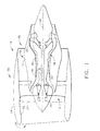
- FIG. 1 is a schematic illustration of an exemplary gas turbine engine 10 that includes a fan assembly 12 and a core engine 13 including a high pressure compressor 14, and a combustor 16 and a high-pressure turbine 18.
- engine 10 also includes a low pressure turbine 20 and a booster 22.
- Fan assembly 12 includes an array of fan blades 24 that extend radially outward from a rotor disc 26.
- Engine 10 has an intake side 28 and an exhaust side 30.
- Fan assembly 12 and turbine 20 are coupled by a first rotor shaft 31, and compressor 14 and turbine 18 are coupled by a second rotor shaft 32.
- a fan casing 50 is coupled radially outward from and extends circumferentially around fan assembly 12.
- Fan casing 50 includes a radially inner fan casing 52 and a radially outer fan casing 54.
- an engine casing 56 is coupled to and extends circumferentially around core engine 13.
- Airflow (not shown in Figure 1 ) from combustor 16 drives turbines 18 and 20, and turbine 20 drives fan assembly 12 by way of shaft 31.
- Figure 2 is a schematic view of gas turbine engine 10 including an exemplary heat exchanger 100 that is coupled between inner fan casing 52 and outer fan casing 54.
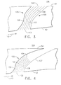
- Figure 3 is an enlarged schematic view of an embodiment of the heat exchanger shown in Figure 2 .
- Figure 4 is an enlarged schematic view of an alternative embodiment of the heat exchanger shown in Figure 2 .
- heat exchanger 100 includes an inlet 102, an outlet 104, and a curvilinear body 105 that extends between inlet 102 and outlet 104.
- curvilinear body 105 extends between inlet 102 and outlet 104 such that at least one curved portion 106 is defined in curvilinear body 105.
- inlet 102 is coupled directly to inner fan casing 52 without an inlet plenum and outlet 104 is coupled directly to outer fan casing 54 without an outlet plenum.
- inlet 102 is coupled directly to inner fan casing 52 without an inlet plenum and outlet 104 is coupled to a curvilinear outlet plenum 107 that is coupled to outer fan casing 54.
- fabricating heat exchanger 100 without an inlet plenum and/or an outlet plenum enables heat exchanger 100 to be coupled to engine 10 without adding as much weight to engine 10 as other known heat exchangers add. Further, fabricating heat exchanger 100 without an inlet plenum and/or an outlet plenum enables drag to occur within heat exchanger 100 while simultaneously exchanging heat within heat exchanger 100.
- heat exchanger 100 may be fabricated with both an inlet plenum and an outlet plenum, while maintaining many of the benefits described herein. Specifically, in one embodiment, heat exchanger 100 may be fabricated with an inlet plenum and an outlet plenum using methods that are known to those skilled in the art.
- a plurality of curvilinear heat exchanger elements 108 extend through curvilinear body 105. More specifically, heat exchanger elements 108 each extend from inlet 102 to outlet 104, and as such, a plurality of passageways 110 are defined between adjacent pairs of heat exchanger elements 108.
- heat exchanger elements 108 and passageways 110 are each formed with a curvilinear shape that is substantially similar to the curvilinear shape of curvilinear body 105. In another embodiment, at least one of a size, an orientation, and a relative location of each heat exchanger element 108 is variable.
- heat exchanger 100 has a smaller volume than known heat exchangers, and as such, adjacent pairs of heat exchanger elements 108 are positioned closer together than in known heat exchangers. Accordingly, passageways 110 are narrower than in known heat exchangers.
- airflow 112 is outboard or ambient air.
- airflow 112 is channeled directly into heat exchanger 100 without passing through an inlet plenum or a diffuser.
- airflow 112 is channeled directly into inlet 102 and through passageways 110 to facilitate heat exchange between the oil and airflow 112. Specifically, the oil is facilitated to be cooled as airflow 112 passes through passageways 110 and past heat exchanger elements 108.
- spent airflow 112 is discharged from heat exchanger 100 through outlet 104 without passing through an outlet plenum.
- the spent airflow is discharged to an area 114 external to engine 10.
- airflow 112 is discharged through outlet plenum 107 to area 114.
- passageways 110 facilitate increasing an amount of heat exchange between airflow 112 and the oil.
- passageways 110 are narrow, and therefore, enable a greater amount of contact between heat exchanger elements 108 and airflow 112 while requiring less airflow for heat exchange than in known heat exchangers.
- the curvilinear shape of heat exchanger 100 enables airflow 112 to flow within the curved passageways 110, thereby further increasing contact between airflow 112 and heat exchanger elements 108.
- airflow 112 is not diffused or channeled through an inlet plenum while being channeled into heat exchanger 100.
- reverse flow losses, aerodynamic losses, and pressure losses of airflow 112 are facilitated to be reduced within heat exchanger 100.
- reverse flow losses, aerodynamic losses, and pressure losses of airflow 112 are facilitated to be reduced by as much as 20%.
- heat exchanger 100 facilitates improving an efficiency of engine 10 thereby reducing time and/or costs associated with maintaining engine 10.
- FIG 5 is a schematic view of gas turbine engine 10 including an exemplary heat exchanger 200 that is coupled to core engine casing 56.
- Figure 6 is an enlarged schematic view of heat exchanger 200.
- heat exchanger 200 is coupled between engine casing 56 and an attachment apparatus 201 that retains heat exchanger 200 against engine casing 56.
- heat exchanger 200 includes an inlet 202, an outlet 204, and a curvilinear body 206 that extends between inlet 202 and outlet 204. Specifically, curvilinear body 206 extends between inlet 202 and outlet 204 such that at least one curved portion 207 is defined in curvilinear body 206.
- inlet 202 and outlet 204 are coupled to core engine casing 56 without an inlet plenum or an outlet plenum.
- fabricating heat exchanger 200 without an inlet plenum or an outlet plenum enables heat exchanger 200 to be coupled to engine 10 without adding as much weight to engine 10 as other known heat exchangers add. Further, fabricating heat exchanger 200 without an inlet plenum and/or an outlet plenum reduces an amount of drag within heat exchanger 200, thereby increasing an amount of heat exchange within heat exchanger 200.
- a plurality of curvilinear heat exchanger elements 208 extend through curvilinear body 206. More specifically, heat exchanger elements 208 each extend from inlet 202 to outlet 204, and as such, a plurality of passageways 210 are defined between adjacent pairs of heat exchanger elements 208.
- heat exchanger elements 208 and passageways 210 are each formed with a curvilinear shape that is substantially similar to the curvilinear shape of curvilinear body 206. In another embodiment, at least one of a size, an orientation, and a relative location of each heat exchanger element 208 is variable.
- heat exchanger 200 has a smaller volume than known heat exchangers, and as such, adjacent pairs of heat exchanger elements 208 are positioned closer together than in known heat exchangers. Accordingly, passageways 210 are narrower than in known heat exchangers.
- airflow 212 is channeled directly into heat exchanger 200 without passing through an inlet plenum or a diffuser.
- airflow 212 is channeled directly into inlet 202 and through passageways 210 to facilitate heat exchange between the oil and airflow 212.
- the oil is facilitated to be cooled as airflow 212 passes through passageways 210 and past heat exchanger elements 208.
- Spent airflow 212 is discharged from heat exchanger 200 through outlet 204 without passing through an outlet plenum and is discharged back onto core engine casing 56.
- passageways 210 facilitate increasing an amount of heat exchange between airflow 212 and the oil.
- passageways 210 are narrow, and therefore, enable a greater amount of contact between heat exchanger elements 208 and airflow 212 while requiring less airflow for heat exchange than in known heat exchangers.
- the curvilinear shape of heat exchanger 200 enables airflow 212 to flow within passageways 210, thereby increasing contact between airflow 212 and heat exchanger elements 208.
- airflow 212 is not diffused or channeled through an inlet plenum while being channeled into heat exchanger 200.
- reverse flow losses, aerodynamic losses, and pressure losses of airflow 212 are facilitated to be reduced within heat exchanger 200.
- reverse flow losses, aerodynamic losses, and pressure losses of airflow 112 are facilitated to be reduced by as much as 20%.
- heat exchanger 200 facilitates improving an efficiency of engine 10 thereby reducing time and/or costs associated with maintaining engine 10.
- a method of assembling a turbine engine includes providing a heat exchanger having a curvilinear body. The method also includes coupling the heat exchanger to at least one of a fan casing and an engine casing of the turbine engine.
- the curvilinear body facilitates reducing pressure losses in airflow channeled into the heat exchanger.
- the heat exchanger is coupled to at least one of the fan casing and the engine casing without an outlet plenum. Accordingly, the airflow is discharged directly from the heat exchanger without passing through an outlet plenum.
- the heat exchanger is coupled to at least one of a fan casing and an engine casing of the turbine engine without an inlet plenum.
- the airflow is channeled directly into the heat exchanger without passing through an inlet plenum.
- the heat exchanger is coupled to at least one of a fan casing and an engine casing of the turbine engine without a diffuser. Accordingly, the airflow is channeled into the heat exchanger without passing through a diffuser.
- the method also includes extending a plurality of curvilinear heat exchanger elements through the curvilinear body; and varying at least one of a size, orientation, and relative location of each heat exchanger element. In one embodiment, varying at least one of a size, orientation, and relative location of each heat exchanger element facilitates increasing an amount of contact between the airflow and the heat exchanger elements. In another embodiment, providing a heat exchanger having a curvilinear body facilitates reducing an amount of air required to cool oil flowing through the heat exchanger elements.
- the above-described systems and methods facilitate increasing heat transfer within a turbine engine heat exchanger. Specifically, the amount of heat transfer is increased because of the combination of curvilinear passages formed within the heat exchanger and the lack of an inlet plenum and/or an outlet plenum. Because of the lack of an inlet plenum, airflow into the heat exchanger is less diffused, and as such, pressure losses are reduced within the heat exchanger. Accordingly, the combination causes a greater amount of airflow to come in contact with the heat exchanger elements that extend through the heat exchanger. As such, the above-described heat exchanger provides a greater amount of heat exchange, while requiring less material and weight than known heat exchangers. Accordingly, the above-described heat exchanger facilitates improving an efficiency of the turbine engine thereby reducing time and/or costs associated with maintaining the turbine engine.
Abstract
Description
- This invention relates generally to turbine engines, and more specifically, to methods and systems for cooling fluid in a turbine engine.
- At least some known turbine engines use heat exchangers to cool oil that is used during engine operations. Specifically, oil from the engine or its generators is channeled through elements in the heat exchanger, and air from a turbine fan is channeled past the heat exchanger elements to cool the oil. Generally, known heat exchangers include an inlet plenum including a diffuser, a heat exchanger block that includes the heat exchanger elements, and an outlet plenum that may include a plurality of passages that may include valve controls. During operation, fan air is channeled into the inlet plenum and through the heat exchanger block prior to being discharged through the outlet plenum. Oil flowing through the heat exchanger elements is cooled by the fan air. In at least some known turbine aircraft engines, the inlet plenum of the heat exchanger is positioned to receive high pressure air discharged from the fan, and the outlet plenum is positioned to facilitate exhausting the high pressure air outboard. In other known turbine aircraft engines, the inlet and the outlet plenums are both coupled to an engine casing, such that high pressure air discharged from the fan is channeled through the heat exchanger prior to being discharged into the fan air or onto engine compartments.
- As is known, the heat transfer capability of the heat exchanger is the greatest in regions having a high heat transfer coefficient, which generally have a significant overlap with regions of local high static pressure defined along the inner walls of the heat exchanger. However, the total pressure of flow passing through the heat exchanger may be decreased due to drag created by the inlet and outlet plenums, and due to passageways formed between the heat exchanger elements. Accordingly, within heat exchangers, high heat transfer capability areas may not be capitalized and therefore, the amount of heat transfer may be reduced.
- In one embodiment according to the present invention, a method of assembling a turbine engine is provided. The method includes providing a heat exchanger having a curvilinear body. The method also includes coupling the heat exchanger to at least one of a fan casing and an engine casing of the turbine engine. The curvilinear body facilitates reducing pressure losses in airflow channeled into the heat exchanger.
- In another embodiment, a heat exchanger for a turbine engine is provided. The heat exchanger includes an inlet, an outlet, and a curvilinear body extending between the inlet and the outlet. The curvilinear body is configured to reduce pressure losses in airflow channeled into the heat exchanger.
- In yet another embodiment, a turbine engine is provided. The turbine engine includes an engine casing and a fan casing coupled to and positioned radially outward from the engine casing. The turbine engine also includes a heat exchanger configured to couple to at least one of the fan casing and the engine casing. The heat exchanger includes an inlet, an outlet, and a curvilinear body extending between the inlet and the outlet. The curvilinear body is configured to reduce pressure losses in airflow channeled into the heat exchanger.
- Various aspects and embodiments of the present invention will now be described in connection with the accompanying drawings, in which:
-
Figure 1 is a schematic view of an exemplary gas turbine engine; -
Figure 2 is a schematic view of the gas turbine engine shown inFigure 1 including an exemplary heat exchanger coupled between an inner fan casing and an outer fan casing; -
Figure 3 is an enlarged schematic view of an embodiment of the heat exchanger shown inFigure 2 ; -
Figure 4 is an enlarged schematic view of an alternative embodiment of the heat exchanger shown inFigure 2 ; -
Figure 5 is a schematic view of the gas turbine engine shown inFigure 1 including an exemplary heat exchanger coupled to a core engine casing; and -
Figure 6 is an enlarged schematic view of a portion of the heat exchanger shown inFigure 5 . - Various aspects of the present invention provide a heat exchanger for a turbine engine that is coupled to at least one of a fan casing and an engine casing of the turbine engine. In the exemplary embodiment, the heat exchanger includes a curvilinear body. In one embodiment, an inlet of the heat exchanger is coupled against an inner fan casing, and an outlet of the heat exchanger is coupled against an outer fan casing that is radially outward from the inner fan casing. In another embodiment, the heat exchanger inlet and outlet are coupled against the engine casing.
- It should be noted that although various aspects of the present invention are described with respect to heat exchangers that used in high by-pass turbine engines, one of ordinary skill in the art would understand that the present invention is not limited to being used in high by-pass turbine engines. Rather, various aspects of the present invention may be used in any engine and/or apparatus requiring heat exchange. For simplicity, embodiments of the present invention are described herein with respect to cooling oil that flows through the heat exchanger. However, as would be appreciated by one of ordinary skill in the art, the present invention is not limited to cooling oil; but rather, the various aspects of present invention may be used to cool any fluid.
-
Figure 1 is a schematic illustration of an exemplarygas turbine engine 10 that includes afan assembly 12 and acore engine 13 including ahigh pressure compressor 14, and acombustor 16 and a high-pressure turbine 18. In the exemplary embodiment,engine 10 also includes alow pressure turbine 20 and abooster 22.Fan assembly 12 includes an array offan blades 24 that extend radially outward from arotor disc 26.Engine 10 has anintake side 28 and anexhaust side 30.Fan assembly 12 andturbine 20 are coupled by afirst rotor shaft 31, andcompressor 14 andturbine 18 are coupled by asecond rotor shaft 32. Afan casing 50 is coupled radially outward from and extends circumferentially aroundfan assembly 12.Fan casing 50 includes a radiallyinner fan casing 52 and a radiallyouter fan casing 54. Moreover, anengine casing 56 is coupled to and extends circumferentially aroundcore engine 13. - During operation, airflows through
fan assembly 12, along acentral axis 34, and compressed air is supplied tohigh pressure compressor 14. The highly compressed air is delivered tocombustor 16. Airflow (not shown inFigure 1 ) fromcombustor 16drives turbines turbine 20drives fan assembly 12 by way ofshaft 31. -
Figure 2 is a schematic view ofgas turbine engine 10 including anexemplary heat exchanger 100 that is coupled betweeninner fan casing 52 andouter fan casing 54.Figure 3 is an enlarged schematic view of an embodiment of the heat exchanger shown inFigure 2 .Figure 4 is an enlarged schematic view of an alternative embodiment of the heat exchanger shown inFigure 2 . - In the exemplary embodiment,
heat exchanger 100 includes aninlet 102, anoutlet 104, and acurvilinear body 105 that extends betweeninlet 102 andoutlet 104. Specifically,curvilinear body 105 extends betweeninlet 102 andoutlet 104 such that at least onecurved portion 106 is defined incurvilinear body 105. In the embodiment illustrated inFigure 3 , and in contrast to other known heat exchangers,inlet 102 is coupled directly toinner fan casing 52 without an inlet plenum andoutlet 104 is coupled directly toouter fan casing 54 without an outlet plenum. In the embodiment illustrated inFigure 4 , and in contrast to other known heat exchangers,inlet 102 is coupled directly toinner fan casing 52 without an inlet plenum andoutlet 104 is coupled to acurvilinear outlet plenum 107 that is coupled toouter fan casing 54. In the exemplary embodiments, fabricatingheat exchanger 100 without an inlet plenum and/or an outlet plenum enablesheat exchanger 100 to be coupled toengine 10 without adding as much weight toengine 10 as other known heat exchangers add. Further, fabricatingheat exchanger 100 without an inlet plenum and/or an outlet plenum enables drag to occur withinheat exchanger 100 while simultaneously exchanging heat withinheat exchanger 100. - As will be appreciated by one of ordinary skill in the art, many of the benefits of
heat exchanger 100 are a result ofcurvilinear body 105. Accordingly, in one embodiment,heat exchanger 100 may be fabricated with both an inlet plenum and an outlet plenum, while maintaining many of the benefits described herein. Specifically, in one embodiment,heat exchanger 100 may be fabricated with an inlet plenum and an outlet plenum using methods that are known to those skilled in the art. - A plurality of curvilinear
heat exchanger elements 108 extend throughcurvilinear body 105. More specifically,heat exchanger elements 108 each extend frominlet 102 tooutlet 104, and as such, a plurality ofpassageways 110 are defined between adjacent pairs ofheat exchanger elements 108. In one embodiment,heat exchanger elements 108 andpassageways 110 are each formed with a curvilinear shape that is substantially similar to the curvilinear shape ofcurvilinear body 105. In another embodiment, at least one of a size, an orientation, and a relative location of eachheat exchanger element 108 is variable. Moreover, in each embodiment,heat exchanger 100 has a smaller volume than known heat exchangers, and as such, adjacent pairs ofheat exchanger elements 108 are positioned closer together than in known heat exchangers. Accordingly,passageways 110 are narrower than in known heat exchangers. - In the exemplary embodiment, during operation, oil from
engine 10 is channeled throughheat exchanger elements 108, andairflow 112 discharged fromfan assembly 12 is channeled thoughheat exchanger 100. In an alternative embodiment,airflow 112 is outboard or ambient air. In contrast to known heat exchangers,airflow 112 is channeled directly intoheat exchanger 100 without passing through an inlet plenum or a diffuser. In the exemplary embodiment,airflow 112 is channeled directly intoinlet 102 and throughpassageways 110 to facilitate heat exchange between the oil andairflow 112. Specifically, the oil is facilitated to be cooled asairflow 112 passes throughpassageways 110 and pastheat exchanger elements 108. In the embodiment shown inFigure 3 , spentairflow 112 is discharged fromheat exchanger 100 throughoutlet 104 without passing through an outlet plenum. The spent airflow is discharged to anarea 114 external toengine 10. In the embodiment shown inFigure 4 ,airflow 112 is discharged throughoutlet plenum 107 toarea 114. - In the exemplary embodiment, as
airflow 112 is channeled throughheat exchanger 100,passageways 110 facilitate increasing an amount of heat exchange betweenairflow 112 and the oil. Specifically,passageways 110 are narrow, and therefore, enable a greater amount of contact betweenheat exchanger elements 108 andairflow 112 while requiring less airflow for heat exchange than in known heat exchangers. Moreover, the curvilinear shape ofheat exchanger 100 enablesairflow 112 to flow within thecurved passageways 110, thereby further increasing contact betweenairflow 112 andheat exchanger elements 108. In addition,airflow 112 is not diffused or channeled through an inlet plenum while being channeled intoheat exchanger 100. Accordingly reverse flow losses, aerodynamic losses, and pressure losses ofairflow 112 are facilitated to be reduced withinheat exchanger 100. Specifically, in one embodiment, reverse flow losses, aerodynamic losses, and pressure losses ofairflow 112 are facilitated to be reduced by as much as 20%. - Accordingly, for the reasons given above,
heat exchanger 100 facilitates improving an efficiency ofengine 10 thereby reducing time and/or costs associated with maintainingengine 10. -
Figure 5 is a schematic view ofgas turbine engine 10 including anexemplary heat exchanger 200 that is coupled tocore engine casing 56.Figure 6 is an enlarged schematic view ofheat exchanger 200. In the exemplary embodiment,heat exchanger 200 is coupled betweenengine casing 56 and anattachment apparatus 201 that retainsheat exchanger 200 againstengine casing 56. - In the exemplary embodiment,
heat exchanger 200 includes aninlet 202, anoutlet 204, and acurvilinear body 206 that extends betweeninlet 202 andoutlet 204. Specifically,curvilinear body 206 extends betweeninlet 202 andoutlet 204 such that at least onecurved portion 207 is defined incurvilinear body 206. In the exemplary embodiment, and in contrast to other known heat exchangers,inlet 202 andoutlet 204 are coupled tocore engine casing 56 without an inlet plenum or an outlet plenum. In the exemplary embodiment, fabricatingheat exchanger 200 without an inlet plenum or an outlet plenum enablesheat exchanger 200 to be coupled toengine 10 without adding as much weight toengine 10 as other known heat exchangers add. Further, fabricatingheat exchanger 200 without an inlet plenum and/or an outlet plenum reduces an amount of drag withinheat exchanger 200, thereby increasing an amount of heat exchange withinheat exchanger 200. - A plurality of curvilinear
heat exchanger elements 208 extend throughcurvilinear body 206. More specifically,heat exchanger elements 208 each extend frominlet 202 tooutlet 204, and as such, a plurality ofpassageways 210 are defined between adjacent pairs ofheat exchanger elements 208. In one embodiment,heat exchanger elements 208 andpassageways 210 are each formed with a curvilinear shape that is substantially similar to the curvilinear shape ofcurvilinear body 206. In another embodiment, at least one of a size, an orientation, and a relative location of eachheat exchanger element 208 is variable. Moreover, in each embodiment,heat exchanger 200 has a smaller volume than known heat exchangers, and as such, adjacent pairs ofheat exchanger elements 208 are positioned closer together than in known heat exchangers. Accordingly,passageways 210 are narrower than in known heat exchangers. - In the exemplary embodiment, during operation, oil from
engine 10 is channeled throughheat exchanger elements 208, and airflow 212 discharged fromfan assembly 12 is channeled thoughheat exchanger 200. In an alternative embodiment,airflow 112 is outboard or ambient air. In contrast to known heat exchangers, airflow 212 is channeled directly intoheat exchanger 200 without passing through an inlet plenum or a diffuser. In the exemplary embodiment, airflow 212 is channeled directly intoinlet 202 and throughpassageways 210 to facilitate heat exchange between the oil and airflow 212. Specifically, the oil is facilitated to be cooled as airflow 212 passes throughpassageways 210 and pastheat exchanger elements 208. Spent airflow 212 is discharged fromheat exchanger 200 throughoutlet 204 without passing through an outlet plenum and is discharged back ontocore engine casing 56. - In the exemplary embodiment, as airflow 212 is channeled through
heat exchanger 200,passageways 210 facilitate increasing an amount of heat exchange between airflow 212 and the oil. Specifically,passageways 210 are narrow, and therefore, enable a greater amount of contact betweenheat exchanger elements 208 and airflow 212 while requiring less airflow for heat exchange than in known heat exchangers. Moreover, the curvilinear shape ofheat exchanger 200 enables airflow 212 to flow withinpassageways 210, thereby increasing contact between airflow 212 andheat exchanger elements 208. In addition, airflow 212 is not diffused or channeled through an inlet plenum while being channeled intoheat exchanger 200. Accordingly reverse flow losses, aerodynamic losses, and pressure losses of airflow 212 are facilitated to be reduced withinheat exchanger 200. Specifically, in one embodiment, reverse flow losses, aerodynamic losses, and pressure losses ofairflow 112 are facilitated to be reduced by as much as 20%. - Accordingly, for the reasons given above,
heat exchanger 200 facilitates improving an efficiency ofengine 10 thereby reducing time and/or costs associated with maintainingengine 10. - In one embodiment, a method of assembling a turbine engine is provided. The method includes providing a heat exchanger having a curvilinear body. The method also includes coupling the heat exchanger to at least one of a fan casing and an engine casing of the turbine engine. The curvilinear body facilitates reducing pressure losses in airflow channeled into the heat exchanger. In one embodiment, the heat exchanger is coupled to at least one of the fan casing and the engine casing without an outlet plenum. Accordingly, the airflow is discharged directly from the heat exchanger without passing through an outlet plenum. In another embodiment, the heat exchanger is coupled to at least one of a fan casing and an engine casing of the turbine engine without an inlet plenum. Accordingly, the airflow is channeled directly into the heat exchanger without passing through an inlet plenum. In yet another embodiment, the heat exchanger is coupled to at least one of a fan casing and an engine casing of the turbine engine without a diffuser. Accordingly, the airflow is channeled into the heat exchanger without passing through a diffuser.
- In one embodiment, the method also includes extending a plurality of curvilinear heat exchanger elements through the curvilinear body; and varying at least one of a size, orientation, and relative location of each heat exchanger element. In one embodiment, varying at least one of a size, orientation, and relative location of each heat exchanger element facilitates increasing an amount of contact between the airflow and the heat exchanger elements. In another embodiment, providing a heat exchanger having a curvilinear body facilitates reducing an amount of air required to cool oil flowing through the heat exchanger elements.
- The above-described systems and methods facilitate increasing heat transfer within a turbine engine heat exchanger. Specifically, the amount of heat transfer is increased because of the combination of curvilinear passages formed within the heat exchanger and the lack of an inlet plenum and/or an outlet plenum. Because of the lack of an inlet plenum, airflow into the heat exchanger is less diffused, and as such, pressure losses are reduced within the heat exchanger. Accordingly, the combination causes a greater amount of airflow to come in contact with the heat exchanger elements that extend through the heat exchanger. As such, the above-described heat exchanger provides a greater amount of heat exchange, while requiring less material and weight than known heat exchangers. Accordingly, the above-described heat exchanger facilitates improving an efficiency of the turbine engine thereby reducing time and/or costs associated with maintaining the turbine engine.
- As used herein, an element or step recited in the singular and proceeded with the word "a" or "an" should be understood as not excluding plural said elements or steps, unless such exclusion is explicitly recited. Furthermore, references to "one embodiment" of the present invention are not intended to be interpreted as excluding the existence of additional embodiments that also incorporate the recited features.
- Exemplary embodiments of systems and methods for exchanging heat in a turbine engine are described above in detail. The systems and methods illustrated are not limited to the specific embodiments described herein, but rather, components of the system may be utilized independently and separately from other components described herein. Further, steps described in the method may be utilized independently and separately from other steps described herein.
- While the invention has been described in terms of various specific embodiments, those skilled in the art will recognize that the invention can be practiced with modification within the spirit and scope of the claims.
Claims (10)
- A heat exchanger (100) for a turbine engine (10), said heat exchanger comprising:an inlet (102) and an outlet (104); anda curvilinear body (105) extending between said inlet and said outlet, said curvilinear body configured to reduce pressure losses in airflow (112) channeled into said heat exchanger.
- A heat exchanger (100) in accordance with Claim 1, wherein said heat exchanger outlet (104) is configured to couple to at least one of a fan casing (50) and an engine casing (56) of the turbine engine (10) without an outlet plenum, such that the airflow (112) is discharged directly from said heat exchanger without passing through an outlet plenum.
- A heat exchanger (100) in accordance with any preceding Claim, wherein said heat exchanger inlet (102) is configured to couple to at least one of a fan casing (50) and an engine casing (56) of the turbine engine (10) without an inlet plenum, such that the airflow (112) is channeled directly into said heat exchanger without passing through an inlet plenum.
- A heat exchanger (100) in accordance with any preceding Claim, further comprising a plurality of curvilinear heat exchanger elements (108) that extend through said curvilinear body (105), wherein at least one of a size, orientation, and relative location of each said heat exchanger element is variable.
- A heat exchanger (100) in accordance with any preceding Claim, wherein each said heat exchanger element (108) is configured to vary in size, orientation, and relative location to increase an amount of contact between the airflow (112) and said heat exchanger elements.
- A heat exchanger (100) in accordance with Claim 4 or Claim 5 when dependent thereon, wherein said curvilinear body (105) is configured to reduce a volume of air required to cool oil flowing through said heat exchanger elements (108).
- A heat exchanger (100) in accordance with any preceding Claim, wherein said heat exchanger is configured to couple to at least one of a fan casing (50) and an engine casing (56) of the turbine engine (10) without a diffuser such that the airflow (112) is channeled into said heat exchanger without passing through a diffuser.
- A turbine engine (10) comprising:an engine casing (56);a fan casing (50) coupled to and positioned radially outward from said engine casing; anda heat exchanger (100) configured to couple to at least one of said fan casing and said engine casing, said heat exchanger comprising:an inlet (102) and an outlet (104); anda curvilinear body (105) extending between said inlet and said outlet, said curvilinear body configured to reduce pressure losses in airflow (112) channeled into said heat exchanger.
- A turbine engine (10) in accordance with Claim 8, wherein said heat exchanger outlet (104) is configured to couple to at least one of said fan casing (50) and said engine casing (56) without an outlet plenum, such that the airflow (112) is discharged directly from said heat exchanger (100) without passing through an outlet plenum.
- A turbine engine (10) in accordance with Claim 8 or Claim 9, wherein said heat exchanger inlet (102) is configured to couple to at least one of said fan casing (50) and said engine casing (56) without an inlet plenum, such that the airflow (112) is channeled directly into said heat exchanger (100) without passing through an inlet plenum.
Applications Claiming Priority (1)
| Application Number | Priority Date | Filing Date | Title |
|---|---|---|---|
| US11/774,179 US8763363B2 (en) | 2007-07-06 | 2007-07-06 | Method and system for cooling fluid in a turbine engine |
Publications (2)
| Publication Number | Publication Date |
|---|---|
| EP2011988A2 true EP2011988A2 (en) | 2009-01-07 |
| EP2011988A3 EP2011988A3 (en) | 2014-05-07 |
Family
ID=39580227
Family Applications (1)
| Application Number | Title | Priority Date | Filing Date |
|---|---|---|---|
| EP08158642.2A Withdrawn EP2011988A3 (en) | 2007-07-06 | 2008-06-20 | Heat exchanger for a turbine engine |
Country Status (4)
| Country | Link |
|---|---|
| US (1) | US8763363B2 (en) |
| EP (1) | EP2011988A3 (en) |
| JP (1) | JP5274125B2 (en) |
| CN (1) | CN101338701B (en) |
Cited By (7)
| Publication number | Priority date | Publication date | Assignee | Title |
|---|---|---|---|---|
| EP2339123A1 (en) * | 2009-12-23 | 2011-06-29 | Techspace Aero S.A. | Inner side of the annular bypass duct of a turbojet engine and method for assembling such an annular duct |
| FR2989109A1 (en) * | 2012-04-05 | 2013-10-11 | Snecma | Stator part for use in blade adjustment outlet of e.g. turbojet of aircraft, has strips and stator blade arranged against each other to define passages for flow of airflow, and circulating unit for circulating fluid to be cooled by airflow |
| EP2522831A3 (en) * | 2011-05-12 | 2014-05-07 | Rolls-Royce Deutschland Ltd & Co KG | Turbojet engine with oil cooler in the engine nacelle |
| WO2014149100A1 (en) * | 2013-03-15 | 2014-09-25 | Rolls-Royce North American Technologies, Inc. | Heat exchanger integrated with a gas turbine engine and adaptive flow control |
| EP3044440A4 (en) * | 2013-09-10 | 2017-07-19 | United Technologies Corporation | Fluid injector for cooling a gas turbine engine component |
| WO2018009259A3 (en) * | 2016-05-11 | 2018-03-01 | General Electric Company | Gas turbine engine having a surface cooler with ogv oriented fin angles |
| FR3074532A1 (en) * | 2017-12-01 | 2019-06-07 | Safran Aircraft Engines | GAS-LIQUID HEAT EXCHANGER FOR TURBOMACHINE, COMPRISING A SURFACE AT LEAST PARTIALLY AERODYNAMIC |
Families Citing this family (23)
| Publication number | Priority date | Publication date | Assignee | Title |
|---|---|---|---|---|
| WO2015047533A1 (en) | 2013-09-24 | 2015-04-02 | United Technologies Corporation | Bypass duct heat exchanger placement |
| US10066550B2 (en) | 2014-05-15 | 2018-09-04 | Rolls-Royce North American Technologies, Inc. | Fan by-pass duct for intercooled turbo fan engines |
| US10634054B2 (en) | 2014-10-21 | 2020-04-28 | United Technologies Corporation | Additive manufactured ducted heat exchanger |
| US9810150B2 (en) * | 2014-10-21 | 2017-11-07 | United Technologies Corporation | Heat exchanger assembly |
| CN105525992B (en) * | 2014-10-21 | 2020-04-14 | 联合工艺公司 | Additive manufactured ducted heat exchanger system with additive manufactured cowling |
| US10907500B2 (en) * | 2015-02-06 | 2021-02-02 | Raytheon Technologies Corporation | Heat exchanger system with spatially varied additively manufactured heat transfer surfaces |
| BE1024081B1 (en) | 2015-03-20 | 2017-11-13 | Safran Aero Boosters S.A. | COOLING TURBOMACHINE BY EVAPORATION |
| US10125684B2 (en) * | 2015-12-29 | 2018-11-13 | Pratt & Whitney Canada Corp. | Surface cooler for aero engine |
| US10344674B2 (en) | 2016-01-08 | 2019-07-09 | General Electric Company | Heat exchanger for embedded engine applications: transduct segments |
| US10126062B2 (en) | 2016-01-08 | 2018-11-13 | General Electric Company | Heat exchanger for embedded engine applications |
| US10184400B2 (en) | 2016-01-08 | 2019-01-22 | General Electric Company | Methods of cooling a fluid using an annular heat exchanger |
| US11002290B2 (en) | 2016-01-08 | 2021-05-11 | General Electric Company | Heat exchanger for embedded engine applications: curvilinear plate |
| US10443436B2 (en) | 2016-07-01 | 2019-10-15 | General Electric Company | Modular annular heat exchanger |
| US10364750B2 (en) | 2017-10-30 | 2019-07-30 | General Electric Company | Thermal management system |
| GB201718796D0 (en) * | 2017-11-14 | 2017-12-27 | Rolls Royce Plc | Gas turbine engine having an air-oil heat exchanger |
| US11262144B2 (en) * | 2017-12-29 | 2022-03-01 | General Electric Company | Diffuser integrated heat exchanger |
| US10941706B2 (en) | 2018-02-13 | 2021-03-09 | General Electric Company | Closed cycle heat engine for a gas turbine engine |
| US11143104B2 (en) | 2018-02-20 | 2021-10-12 | General Electric Company | Thermal management system |
| FR3081514B1 (en) * | 2018-05-28 | 2020-06-05 | Safran Aircraft Engines | AIRCRAFT POWDER ASSEMBLY AND METHOD FOR REDUCING VENTILATION AIR FLOW IN THE AIRCRAFT POWDER ASSEMBLY |
| US11015534B2 (en) | 2018-11-28 | 2021-05-25 | General Electric Company | Thermal management system |
| BE1027057B1 (en) * | 2019-02-18 | 2020-09-14 | Safran Aero Boosters Sa | AIR-OIL HEAT EXCHANGER |
| FR3096444B1 (en) * | 2019-05-20 | 2021-05-07 | Safran | OPTIMIZED HEAT EXCHANGE SYSTEM |
| US11313276B2 (en) | 2019-08-01 | 2022-04-26 | Rolls-Royce Deutschland Ltd & Co Kg | Supersonic gas turbine engine |
Citations (5)
| Publication number | Priority date | Publication date | Assignee | Title |
|---|---|---|---|---|
| US4254618A (en) * | 1977-08-18 | 1981-03-10 | General Electric Company | Cooling air cooler for a gas turbofan engine |
| GB2234805A (en) * | 1989-08-04 | 1991-02-13 | Rolls Royce Plc | A heat exchanger arrangement for a gas turbine engine |
| US5269135A (en) * | 1991-10-28 | 1993-12-14 | General Electric Company | Gas turbine engine fan cooled heat exchanger |
| EP0924409A2 (en) * | 1997-12-22 | 1999-06-23 | United Technologies Corporation | Heat exchanger system for a gas turbine engine |
| US20050150970A1 (en) * | 2004-01-13 | 2005-07-14 | Snecma Moteurs | Cooling system for hot parts of an aircraft engine, and aircraft engine equipped with such a cooling system |
Family Cites Families (24)
| Publication number | Priority date | Publication date | Assignee | Title |
|---|---|---|---|---|
| GB1322405A (en) * | 1970-10-02 | 1973-07-04 | Secr Defence | Oil systems for gas turbine engines |
| GB9027782D0 (en) * | 1990-12-21 | 1991-02-13 | Rolls Royce Plc | Heat exchanger apparatus |
| CA2062887A1 (en) | 1991-04-22 | 1992-10-23 | Franklin E. Miller | Heat exchanger system |
| US5305616A (en) * | 1992-03-23 | 1994-04-26 | General Electric Company | Gas turbine engine cooling system |
| US5392614A (en) * | 1992-03-23 | 1995-02-28 | General Electric Company | Gas turbine engine cooling system |
| US5918458A (en) * | 1997-02-14 | 1999-07-06 | General Electric Company | System and method of providing clean filtered cooling air to a hot portion of a gas turbine engine |
| US6775406B1 (en) * | 1998-08-25 | 2004-08-10 | Douglas L. Watson | Colorizing a black-and-white image to facilitate the identification of a pattern in the image |
| US6557337B1 (en) * | 1998-09-25 | 2003-05-06 | Alm Development, Inc. | Gas turbine engine |
| US6356868B1 (en) * | 1999-10-25 | 2002-03-12 | Comverse Network Systems, Inc. | Voiceprint identification system |
| US6295803B1 (en) * | 1999-10-28 | 2001-10-02 | Siemens Westinghouse Power Corporation | Gas turbine cooling system |
| US20020053975A1 (en) * | 2000-01-12 | 2002-05-09 | The Chamberlain Group, Inc. | Entry control system |
| US6584778B1 (en) * | 2000-05-11 | 2003-07-01 | General Electric Co. | Methods and apparatus for supplying cooling air to turbine engines |
| JP2001330381A (en) | 2000-05-25 | 2001-11-30 | Toray Eng Co Ltd | Stacked total enthalpy heat exchanger unit |
| US7305478B2 (en) * | 2000-06-08 | 2007-12-04 | Symbol Technologies, Inc. | Bar code symbol ticketing for authorizing access in a wireless local area communications network |
| US6864911B1 (en) * | 2000-10-26 | 2005-03-08 | Hewlett-Packard Development Company, L.P. | Linkable digital cameras for an image capture system |
| US8954432B2 (en) * | 2000-11-15 | 2015-02-10 | Mark Frigon | Users tagging users in photos online |
| US6816205B2 (en) * | 2001-04-20 | 2004-11-09 | Edmond Louis Dudkowski | System and method for camera selection tallying for multiple camera video production |
| US7031700B1 (en) * | 2001-11-14 | 2006-04-18 | Sprint Spectrum L.P. | Method and system for location-based group conference initiation |
| GB2389174B (en) * | 2002-05-01 | 2005-10-26 | Rolls Royce Plc | Cooling systems |
| US7334411B2 (en) * | 2004-04-21 | 2008-02-26 | General Electric Company | Gas turbine heat exchanger assembly and method for fabricating same |
| WO2006040687A2 (en) * | 2004-07-19 | 2006-04-20 | Grandeye, Ltd. | Automatically expanding the zoom capability of a wide-angle video camera |
| US7377100B2 (en) * | 2004-08-27 | 2008-05-27 | Pratt & Whitney Canada Corp. | Bypass duct fluid cooler |
| US7730406B2 (en) * | 2004-10-20 | 2010-06-01 | Hewlett-Packard Development Company, L.P. | Image processing system and method |
| US7454894B2 (en) * | 2004-12-07 | 2008-11-25 | United Technologies Corporation | Supplemental oil cooler airflow for gas turbine engine |
-
2007
- 2007-07-06 US US11/774,179 patent/US8763363B2/en not_active Expired - Fee Related
-
2008
- 2008-06-20 EP EP08158642.2A patent/EP2011988A3/en not_active Withdrawn
- 2008-07-03 JP JP2008174298A patent/JP5274125B2/en not_active Expired - Fee Related
- 2008-07-03 CN CN200810130462.XA patent/CN101338701B/en not_active Expired - Fee Related
Patent Citations (5)
| Publication number | Priority date | Publication date | Assignee | Title |
|---|---|---|---|---|
| US4254618A (en) * | 1977-08-18 | 1981-03-10 | General Electric Company | Cooling air cooler for a gas turbofan engine |
| GB2234805A (en) * | 1989-08-04 | 1991-02-13 | Rolls Royce Plc | A heat exchanger arrangement for a gas turbine engine |
| US5269135A (en) * | 1991-10-28 | 1993-12-14 | General Electric Company | Gas turbine engine fan cooled heat exchanger |
| EP0924409A2 (en) * | 1997-12-22 | 1999-06-23 | United Technologies Corporation | Heat exchanger system for a gas turbine engine |
| US20050150970A1 (en) * | 2004-01-13 | 2005-07-14 | Snecma Moteurs | Cooling system for hot parts of an aircraft engine, and aircraft engine equipped with such a cooling system |
Cited By (12)
| Publication number | Priority date | Publication date | Assignee | Title |
|---|---|---|---|---|
| EP2339123A1 (en) * | 2009-12-23 | 2011-06-29 | Techspace Aero S.A. | Inner side of the annular bypass duct of a turbojet engine and method for assembling such an annular duct |
| US8601791B2 (en) | 2009-12-23 | 2013-12-10 | Techspace Aero S.A. | Integration of a surface heat exchanger to the wall of an aerodynamic flowpath by a structure of reinforcement rods |
| EP2522831A3 (en) * | 2011-05-12 | 2014-05-07 | Rolls-Royce Deutschland Ltd & Co KG | Turbojet engine with oil cooler in the engine nacelle |
| US8938944B2 (en) | 2011-05-12 | 2015-01-27 | Rolls-Royce Deutschland Ltd & Co Kg | Aircraft gas-turbine engine with oil cooler in the engine cowling |
| FR2989109A1 (en) * | 2012-04-05 | 2013-10-11 | Snecma | Stator part for use in blade adjustment outlet of e.g. turbojet of aircraft, has strips and stator blade arranged against each other to define passages for flow of airflow, and circulating unit for circulating fluid to be cooled by airflow |
| WO2014149100A1 (en) * | 2013-03-15 | 2014-09-25 | Rolls-Royce North American Technologies, Inc. | Heat exchanger integrated with a gas turbine engine and adaptive flow control |
| US9587561B2 (en) | 2013-03-15 | 2017-03-07 | Rolls-Royce North American Technologies, Inc. | Heat exchanger integrated with a gas turbine engine and adaptive flow control |
| EP3044440A4 (en) * | 2013-09-10 | 2017-07-19 | United Technologies Corporation | Fluid injector for cooling a gas turbine engine component |
| US10480533B2 (en) | 2013-09-10 | 2019-11-19 | United Technologies Corporation | Fluid injector for cooling a gas turbine engine component |
| WO2018009259A3 (en) * | 2016-05-11 | 2018-03-01 | General Electric Company | Gas turbine engine having a surface cooler with ogv oriented fin angles |
| US10823067B2 (en) | 2016-05-11 | 2020-11-03 | General Electric Company | System for a surface cooler with OGV oriented fin angles |
| FR3074532A1 (en) * | 2017-12-01 | 2019-06-07 | Safran Aircraft Engines | GAS-LIQUID HEAT EXCHANGER FOR TURBOMACHINE, COMPRISING A SURFACE AT LEAST PARTIALLY AERODYNAMIC |
Also Published As
| Publication number | Publication date |
|---|---|
| US8763363B2 (en) | 2014-07-01 |
| EP2011988A3 (en) | 2014-05-07 |
| US20090007570A1 (en) | 2009-01-08 |
| JP2009013982A (en) | 2009-01-22 |
| JP5274125B2 (en) | 2013-08-28 |
| CN101338701B (en) | 2015-11-25 |
| CN101338701A (en) | 2009-01-07 |
Similar Documents
| Publication | Publication Date | Title |
|---|---|---|
| US8763363B2 (en) | Method and system for cooling fluid in a turbine engine | |
| US10781772B2 (en) | Integrated heat exchangers for low fan pressure ratio geared turbofan | |
| JP5336618B2 (en) | Gas turbine engine assembly | |
| EP1956192B1 (en) | Gas turbine engine component cooling scheme | |
| US8784047B2 (en) | Gas turbine engine heat exchanger with tapered fins | |
| CA2299148C (en) | Compressor system and methods for reducing cooling airflow | |
| EP3187716A1 (en) | Method and system for compressor and turbine cooling | |
| EP2519724B1 (en) | Gas turbine engine and cooling system | |
| US20190203613A1 (en) | Gas turbine engine fluid cooling systems and methods of assembling the same | |
| EP2358978B1 (en) | Apparatus and method for cooling a turbine airfoil arrangement in a gas turbine engine | |
| EP2020500A2 (en) | Heat exchanger assembly for gas turbine engines | |
| JP2002155701A (en) | Clocked turbine airfoil cooling | |
| EP2762685A1 (en) | Gas turbine engine integrated heat exchanger | |
| US20180320530A1 (en) | Airfoil with tip rail cooling | |
| US10823067B2 (en) | System for a surface cooler with OGV oriented fin angles | |
| US10450874B2 (en) | Airfoil for a gas turbine engine | |
| CN108691571B (en) | Engine component with flow enhancer | |
| EP2565392A2 (en) | Gas turbine engine air cycle system | |
| EP3730764B1 (en) | Gas turbine with multi-stage radial compressor and inter-compressor cross-over pipe heat exchanger | |
| US11873758B1 (en) | Gas turbine engine component with integral heat exchanger | |
| US20230417188A1 (en) | Thermal management system for a gas turbine engine | |
| GB2496852A (en) | Heat exchanger with tapered fins for a gas turbine |
Legal Events
| Date | Code | Title | Description |
|---|---|---|---|
| PUAI | Public reference made under article 153(3) epc to a published international application that has entered the european phase |
Free format text: ORIGINAL CODE: 0009012 |
|
| AK | Designated contracting states |
Kind code of ref document: A2 Designated state(s): AT BE BG CH CY CZ DE DK EE ES FI FR GB GR HR HU IE IS IT LI LT LU LV MC MT NL NO PL PT RO SE SI SK TR |
|
| AX | Request for extension of the european patent |
Extension state: AL BA MK RS |
|
| PUAL | Search report despatched |
Free format text: ORIGINAL CODE: 0009013 |
|
| AK | Designated contracting states |
Kind code of ref document: A3 Designated state(s): AT BE BG CH CY CZ DE DK EE ES FI FR GB GR HR HU IE IS IT LI LT LU LV MC MT NL NO PL PT RO SE SI SK TR |
|
| AX | Request for extension of the european patent |
Extension state: AL BA MK RS |
|
| RIC1 | Information provided on ipc code assigned before grant |
Ipc: F28D 21/00 20060101ALI20140331BHEP Ipc: F02C 7/14 20060101ALI20140331BHEP Ipc: F02K 3/115 20060101AFI20140331BHEP |
|
| 17P | Request for examination filed |
Effective date: 20141107 |
|
| RBV | Designated contracting states (corrected) |
Designated state(s): AT BE BG CH CY CZ DE DK EE ES FI FR GB GR HR HU IE IS IT LI LT LU LV MC MT NL NO PL PT RO SE SI SK TR |
|
| AKX | Designation fees paid |
Designated state(s): DE FR GB |
|
| AXX | Extension fees paid |
Extension state: BA Extension state: MK Extension state: RS Extension state: AL |
|
| STAA | Information on the status of an ep patent application or granted ep patent |
Free format text: STATUS: THE APPLICATION IS DEEMED TO BE WITHDRAWN |
|
| 18D | Application deemed to be withdrawn |
Effective date: 20170103 |