EP1897790B1 - Device for coupling a towed vehicle to a towing vehicle, as well as a vehicle combination - Google Patents
Device for coupling a towed vehicle to a towing vehicle, as well as a vehicle combination Download PDFInfo
- Publication number
- EP1897790B1 EP1897790B1 EP07017462A EP07017462A EP1897790B1 EP 1897790 B1 EP1897790 B1 EP 1897790B1 EP 07017462 A EP07017462 A EP 07017462A EP 07017462 A EP07017462 A EP 07017462A EP 1897790 B1 EP1897790 B1 EP 1897790B1
- Authority
- EP
- European Patent Office
- Prior art keywords
- coupling
- drawbar assembly
- vehicle
- pivot axis
- frame
- Prior art date
- Legal status (The legal status is an assumption and is not a legal conclusion. Google has not performed a legal analysis and makes no representation as to the accuracy of the status listed.)
- Not-in-force
Links
- 230000008878 coupling Effects 0.000 title claims abstract description 43
- 238000010168 coupling process Methods 0.000 title claims abstract description 43
- 238000005859 coupling reaction Methods 0.000 title claims abstract description 43
- 230000007935 neutral effect Effects 0.000 claims abstract description 38
- 230000007246 mechanism Effects 0.000 description 6
- 230000005540 biological transmission Effects 0.000 description 4
- 230000000694 effects Effects 0.000 description 3
- 230000009471 action Effects 0.000 description 2
- 230000008901 benefit Effects 0.000 description 2
- 229910000831 Steel Inorganic materials 0.000 description 1
- 230000004323 axial length Effects 0.000 description 1
- 230000008859 change Effects 0.000 description 1
- 239000002131 composite material Substances 0.000 description 1
- 230000006835 compression Effects 0.000 description 1
- 238000007906 compression Methods 0.000 description 1
- 230000006872 improvement Effects 0.000 description 1
- 230000009347 mechanical transmission Effects 0.000 description 1
- 239000000203 mixture Substances 0.000 description 1
- 230000000717 retained effect Effects 0.000 description 1
- 239000010959 steel Substances 0.000 description 1
Images


Classifications
-
- B—PERFORMING OPERATIONS; TRANSPORTING
- B62—LAND VEHICLES FOR TRAVELLING OTHERWISE THAN ON RAILS
- B62D—MOTOR VEHICLES; TRAILERS
- B62D53/00—Tractor-trailer combinations; Road trains
- B62D53/04—Tractor-trailer combinations; Road trains comprising a vehicle carrying an essential part of the other vehicle's load by having supporting means for the front or rear part of the other vehicle
- B62D53/08—Fifth wheel traction couplings
- B62D53/0857—Auxiliary semi-trailer handling or loading equipment, e.g. ramps, rigs, coupling supports
- B62D53/0864—Dollies for fifth wheel coupling
-
- B—PERFORMING OPERATIONS; TRANSPORTING
- B62—LAND VEHICLES FOR TRAVELLING OTHERWISE THAN ON RAILS
- B62D—MOTOR VEHICLES; TRAILERS
- B62D13/00—Steering specially adapted for trailers
- B62D13/04—Steering specially adapted for trailers for individually-pivoted wheels
-
- B—PERFORMING OPERATIONS; TRANSPORTING
- B62—LAND VEHICLES FOR TRAVELLING OTHERWISE THAN ON RAILS
- B62D—MOTOR VEHICLES; TRAILERS
- B62D53/00—Tractor-trailer combinations; Road trains
- B62D53/04—Tractor-trailer combinations; Road trains comprising a vehicle carrying an essential part of the other vehicle's load by having supporting means for the front or rear part of the other vehicle
- B62D53/08—Fifth wheel traction couplings
Definitions
- the present invention relates to a device for coupling a towed vehicle to a towing vehicle, comprising a frame, at least one wheel pair for moving the device, the wheels of said at least one wheel pair are of the steering type, a drawbar assembly which can be pivotally coupled to the towing vehicle about a first vertical pivot axis on the one hand and which is pivotally connected to the frame about a second vertical pivot axis on the other hand, as well as a coupling plate for pivotally coupling the towed vehicle to the device about a third vertical pivot axis, in which device means are provided for causing the wheels of the steering type to be steered in dependence on the pivoted position of the drawbar assembly about the second vertical pivot axis with respect to the frame.
- LHVs Long and Heavy Vehicles
- Such devices consist of a truck and one or even two trailers.
- the required coupling between the truck and said one or two trailers can be realised by means of devices as referred to in the introduction, which devices are also referred to as "dollies" in technical jargon.
- LHVs are also being used in other countries, whether or not within the framework of an experimental project.
- European patent EP-A2-1 466 813 proposes to use a two-axle dolly, a drawbar assembly of which is pivotable about a vertical pivot axis with respect to a frame at the rear end thereof.
- a turntable which is known per se, is provided for being coupled with the kingpin of a trailer, thus realising a pivotable coupling between the dolly and the trailer.
- the associated pivot axis is located behind the pivot axis between the drawbar assembly and the frame.
- the drawbar assembly is provided with an eye for being coupled with a coupling pin at the rear side of the towing vehicle, for example a truck.
- the object of the present invention is to solve or at least alleviate the aforesaid problems.
- the device according to the invention is characterised in that reset means are provided, which reset means act between the frame and the drawbar assembly and act directly on the drawbar assembly for causing the drawbar assembly to pivot back about the second vertical axis from a non-neutral position to a neutral position. In this way a significant improvement as regards the stability of the road behaviour and the tracking of the towed vehicle behind the towing vehicle is realised.
- the reset means comprise at least one cylinder, more preferably at least two cylinders acting in opposite directions.
- the reset means operate on the basis of pneumatic pressure.
- Said pneumatic pressure can be generated by means that are available as standard on the towing vehicle.
- the reset means comprise an air bellows and/or at least one rod which is pivotally connected to the drawbar assembly by means of a pin-slot connection.
- the wheels of said at least one wheel pair are of the steering type.
- a very good control of the steered wheels is obtained as means are provided for causing the wheels of the steering type to be steered in dependence on the pivoted position of the drawbar assembly about the second vertical pivot axis with respect to the frame.
- locking means are provided for locking the drawbar assembly in the neutral position.
- Another, very advantageous preferred embodiment is characterised in that the second vertical pivot axis and the third vertical pivot axis coincide. Because the second pivot axis and the third pivot axis coincide, an improved road behaviour is obtained, but it is nevertheless still possible to have the towing vehicle, the drawbar assembly, the frame and the towed vehicle take up different pivoted positions with respect to each other, because they are not rigidly coupled. In this way it is possible to realise comparatively small turning circles.
- the invention further relates to a vehicle combination comprising a towing vehicle, a towed vehicle and a coupling device for coupling the towed vehicle to the towing vehicle, which coupling device is according to the invention configured in the manner as described above, including its concomitant advantages.
- Figure 1 shows a vehicle combination 1, more specifically a tractor-trailer combination, the tractor being configured as a truck 2 and the trailer being configured as a three-axled trailer.
- the trailer 3 is coupled to the truck 2 by means of a coupling device, hereinafter called dolly 4.
- FIGS 2a , 3 and 4a show the dolly 4 in more detail.
- the dolly 4 comprises a frame 5 with longitudinal girders 6a, 6b and cross beams 7a, 7b, 7c.
- the dolly 4 further comprises two wheel pairs 8, 9 with wheels 7a, 8b and 9a, 9b, respectively.
- the dolly further comprises a drawbar assembly 10, which is at least substantially made up of a drawbar member 11 at the front of the frame 5, a drawbar disc 12 and a coupling member 13 (also refer to figure 3 ), which forms the connection between the drawbar member and the drawbar disc 12.
- the drawbar member 11 has a cranked shape, seen in the vertical plane, and is provided with a coupling eye 14 at the front side, which is to mate with a coupling pin (not shown in detail) forming part of the truck 2 at the rear side thereof.
- a coupling pin (not shown in detail) forming part of the truck 2 at the rear side thereof.
- the drawbar disc 12 is substantially disc-shaped, the diameter of which disc shape being substantially equal to the width of the frame 5. At its rear side, the disc shape of the drawbar plate blends into a projecting stop edge 16 between the rear wheels 9a, 9b.
- the drawbar disc 12, and thus the entire drawbar assembly 10, is pivotally supported about the vertical pivot axis 17 with respect to the frame 5.
- the dolly 4 is provided with a horizontal guide 18, which substantially comprises two arcuate guide plates 18a and 18b positioned one above the other, between which a part of the coupling member 13 is positioned for guiding cooperation with the upper side and the bottom side, respectively, of the coupling member 13.
- the dolly 4 furthermore comprises a coupling plate 19 provided with a wedge-shaped slot 20, which is disposed above the drawbar disc 12.
- a coupling plate 19 provided with a wedge-shaped slot 20, which is disposed above the drawbar disc 12.
- the trailer 3 can be coupled with the dolly 4, with a pin (not shown), usually referred to as kingpin, being retained in the front end of the slot 20 by means of a safety catch.
- a connection enables the trailer 3 to pivot about the vertical pivot axis 21, which coincides with the central axis of the kingpin, with respect to the coupling plate 19 and/or to pivot jointly with the coupling plate 19 about said vertical pivot axis 21 with respect to the frame 5.
- the vertical pivot axis 21 coincides with the vertical pivot axis 17 for the drawbar assembly 10.
- the coupling plate 19 is in principle rigidly connected either to the frame 5 or to the drawbar disc 12, but it may also be pivotally connected to the frame 5 or to the drawbar disc 12 about a pivot axis that coincide
- the dolly 4 is provided with a steering mechanism for steering the front wheels 8a, 8b in dependence on the pivoted position of the drawbar assembly 10 about the pivot axis 17 with respect to the frame 5.
- the steering mechanism is shown in figures 4a and 4b , and the operation of said mechanism will become clear upon comparing figures 4a and 4b .
- the steering mechanism comprises: a sliding rod 24 which is movable in its longitudinal direction within a sliding member 25, steering rods 26a, 26b, a composite transmission element 27, track rods 28a, 28b and steering levers 29a, 29b, which are rigidly connected to the axles of the respective wheels 8b, 8a.
- the sliding member 25 is pivotally supported (together with the sliding rod 24) with respect to the frame 5 about a vertical axis 30. At its front end, the sliding rod 24 is pivotally connected to the drawbar disc 12 about a pivot axis 23.
- the steering rods 26a, 26b are pivotally connected to the sliding member 25 and the transmission element 27 at their ends.
- the track rods 28a, 28b are pivotally connected to the steering levers 29a, 29b at one end and to the transmission element 27 at the opposite end.
- the transmission element 27 is pivotally supported about a vertical pivot axis 31 with respect to the frame 5.
- Figure 5 shows how a vehicle combination 1 takes a turn, more specifically it shows the pivoted positions which the truck 1, the drawbar assembly 10, the frame 5 and the trailer successively take up with respect to each other.
- the figure also shows how the front wheels 8a, 8b take up a steering (non-neutral) position as a result of the action of the steering mechanism described above with reference to figures 4a and 4b .
- the vehicle combination 1 has a comparatively small turning circle, which effect is enhanced by the steered front wheels 8a, 8b. Because the pivot axes 17 and 21 coincide, the vehicle combination will exhibit a stable steering behaviour, and the trailer 3 will exhibit a stronger tendency to track well behind the truck 2.
- cylinders 32a and 32b which are disposed directly opposite each other at the location of the stop edge 16.
- the cylinders 32a, 32b are connected to the longitudinal girders 6a, 6b, respectively, of the frame 5.
- the cylinders 32a, 32b abut against the side edge of the stop edge 16 that faces towards the cylinder 32a, 32b in question in the neutral position of the drawbar assembly 10 that is shown in figure 2a .
- the length of the other cylinder 32a, 32b (cylinder 32b in figure 2b ) does not change, and consequently said cylinder does not exert a force that opposes the pivoting of the drawbar assembly 10 from the neutral position.
- the action of the cylinders 32a, 32b which may be hydraulic or pneumatic cylinders for that matter, additionally enhances the stability of the steering behaviour, which manifests itself in, for example, an accelerated return to the neutral position of the drawbar assembly 10 after the vehicle combination 1 has taken a turn.
- the drawbar assembly 10 can be locked in the neutral position, for example by using a pin-hole coupling as described in EP-A2-1 466 813 .
- the cylinders 32a, 32b for this purpose, which is done by increasing the pressure in said cylinders temporarily.
- Figures 6a-7 relate to a dolly 51 according to a second preferred embodiment of the invention.
- the dolly 51 is to a large extent identical to the dolly 4. Consequently, corresponding parts are indicated by the same numerals for easy reference. For a more detailed explanation of the parts in question, reference is made to the preceding description of the dolly 4.
- the dolly 51 and the dolly 4 are different from each other in that different measures have been taken to ensure that a semitrailer 3 will track well behind a truck 2 also after taking a turn.
- the pivot axes 17 and 21 coincide with the dolly 51.
- the dolly 51 does not use cylinders 32a and 32b, which act in opposite directions on the stop edge 16, as is the case with the dolly 4, but it makes use of air bellows 52a, 52b.
- the air bellows 52a, 52b which are known to those skilled in the art, comprise a pot body 53a, 53b, respectively, and a flexible bellows body 54a, 54b, respectively.
- the air bellows 52a, 52b are each connected to the pneumatic pressure circuit of the truck 2, with a pressure of, for example, about 5 bar prevailing in the air bellows 52a, 52b during normal use.
- the pot bodies 53a, 53b extend within the bellows bodies 54a, 54 along a limited portion of their axial length.
- the bellows bodies 54a, 54b each comprise a disc-shaped steel mounting plate 55a, 55b, via which mounting plates 55a, 55b the air bellows 52a, 52b are fixedly connected to a cross beam 56, which extends between the rear ends of the longitudinal girders 6a, 6b.
- coupling rods 57a, 57b are pivotally connected to the associated pot bodies 53a, 53b about vertical pivot axes 81 a, 81 b. At their free ends, the coupling rods 57a, 57b are provided with slotted holes 58a, 58b.
- the drawbar disc 59 which does not have a stop edge such as the stop edge 16 of the drawbar disc 12, is provided with two pivot pins 60a, 60b, which extend downwards from the drawbar disc 59 into the respective slotted holes 58a, 58b.
- the pivot pins 60a, 60b are located at the end of the slotted holes 58a, 58b that faces towards the associated air bellows 52a, 52b.
- the connection between the coupling rods 57a, 57b and the drawbar disc 59 via the pivot pins 60a, 60b extending within the slotted holes 58a, 58b enables the coupling rods 57a, 57b to pivot about the central axes of the pivot pins 60a, 60b, respectively.
- the pivot pin 60a, 60b that is located on the outside bend side will move within the associated slotted holes 58a, 58b.
- the length of the slotted holes 58a, 58b has been selected so that in the case of a maximum travel of the drawbar member 11 the pivot pin 60a, 60b in question cannot reach or can just reach the opposite end of the slotted hole 58a, 58b.
- the pivot pin 60a, 60b in question will slightly move towards the centre of the dolly 51 upon pivoting of the drawbar disc 59, as a result of which the associated pot body 53a, 53b will move outwards to a very limited extent within the associated bellows body 54a, 54b, without influencing the pneumatic volume of the respective bellows body 54a, 54b to any significant extent.
- pivot pin 60a, 60b that is located on the inside bend side will push the coupling rod 57b in the direction of the air bellows 52b, as a result of which the pot body 53b is pushed into the bellows body 54b at a slightly skewed angle.
- This causes the pneumatic volume of the bellows body 54b to decrease significantly, as a result of which the pressure in the air bellows 52b is increased and consequently an increased resistance develops to push the pivot pin 60b back again, so that the drawbar member 11 will assume its neutral position again.
- the dolly 51 is furthermore provided with guide rods.
- this is the guide rod 61, which extends within the height of the longitudinal girder 6a, 6b and which is pivotally connected to the cross beam 7c about a vertical pivot axis 81.
- the guide rods 62a, 62b which are provided above and below the guide rod 61, respectively, and which are pivotally connected to the cross beam 7c about (aligned) vertical pivot axes 83.
- the guide rods 61, 62a, 62b are rigidly connected to the associated pot body 53a, 53b.
Landscapes
- Engineering & Computer Science (AREA)
- Chemical & Material Sciences (AREA)
- Combustion & Propulsion (AREA)
- Transportation (AREA)
- Mechanical Engineering (AREA)
- Handcart (AREA)
- Steering-Linkage Mechanisms And Four-Wheel Steering (AREA)
- Agricultural Machines (AREA)
- Automatic Cycles, And Cycles In General (AREA)
Abstract
Description
- The present invention relates to a device for coupling a towed vehicle to a towing vehicle, comprising a frame, at least one wheel pair for moving the device, the wheels of said at least one wheel pair are of the steering type, a drawbar assembly which can be pivotally coupled to the towing vehicle about a first vertical pivot axis on the one hand and which is pivotally connected to the frame about a second vertical pivot axis on the other hand, as well as a coupling plate for pivotally coupling the towed vehicle to the device about a third vertical pivot axis, in which device means are provided for causing the wheels of the steering type to be steered in dependence on the pivoted position of the drawbar assembly about the second vertical pivot axis with respect to the frame.
- Such devices are used with so-called Long and Heavy Vehicles (LHVs), which usually have an overall, relatively great length of maximally 25.25 m. Such LHVs consist of a truck and one or even two trailers. The required coupling between the truck and said one or two trailers can be realised by means of devices as referred to in the introduction, which devices are also referred to as "dollies" in technical jargon.
- At the time of the present invention an experimental project with such vehicles has been started in the Netherlands. The aim is in particular to reduce the transport costs and to limit the burden on the environment. An important drawback of LHVs is their limited manoeuvrability, precisely because of their relatively great length and, in conjunction therewith, the road safety risks the use of such LHVs involves. The limited manoeuvrability manifests itself in a relatively large turning circle of LHVs, which is for example objectionable at (smaller) roundabouts. It is (partially) for the above reasons that the Dutch authorities decided to permit only a limited number of LHVs to take part in the experimental project, and that on a limited number of motorway routes. LHVs are also being used in other countries, whether or not within the framework of an experimental project.
- To overcome the above drawback regarding the limited manoeuvrability,
European patent EP-A2-1 466 813 proposes to use a two-axle dolly, a drawbar assembly of which is pivotable about a vertical pivot axis with respect to a frame at the rear end thereof. Behind said pivot axis, a turntable, which is known per se, is provided for being coupled with the kingpin of a trailer, thus realising a pivotable coupling between the dolly and the trailer. The associated pivot axis is located behind the pivot axis between the drawbar assembly and the frame. At its front end the drawbar assembly is provided with an eye for being coupled with a coupling pin at the rear side of the towing vehicle, for example a truck. In total there are three pivot axes, which make it possible to realise a small turning circle. Unfortunately it has become apparent in practice, however, that the use of three such pivot axis leads to an unstable road behaviour, so that there is a risk that the trailer will not track well behind the truck, for example due to the presence of ruts in the road surface. All this requires greater skill on the part of the driver and constitutes a road safety hazard. The wheels of the front axle of the dolly steer in dependence on the pivoted position of the drawbar assembly, and optionally also in dependence on the speed of the dolly. To that end two pneumatic cylinders are provided, whose position can be adjusted by means of a steering mechanism. The position of the pneumatic cylinders determines the steering characteristic. Possible failure of one of the pneumatic cylinders will lead to an overdefined situation as far as the mechanical transmission between the drawbar and the wheels of the front axle is concerned, which may result in an uncontrolled steering characteristic. Another significant drawback of the drawbar assembly according toEP 1 466 813 A2 - The object of the present invention is to solve or at least alleviate the aforesaid problems. In order to accomplish that object, the device according to the invention is characterised in that reset means are provided, which reset means act between the frame and the drawbar assembly and act directly on the drawbar assembly for causing the drawbar assembly to pivot back about the second vertical axis from a non-neutral position to a neutral position. In this way a significant improvement as regards the stability of the road behaviour and the tracking of the towed vehicle behind the towing vehicle is realised.
- For reasons of constructional simplicity it is preferable if the reset means comprise at least one cylinder, more preferably at least two cylinders acting in opposite directions.
- It is advantageous in that regard if only one of said at least two cylinders acts between the frame and the drawbar assembly in a non-neutral position. This has the advantage that the cylinders can take up an extreme position in the neutral position of the drawbar assembly.
- According to another preferred embodiment, the reset means operate on the basis of pneumatic pressure. Said pneumatic pressure can be generated by means that are available as standard on the towing vehicle.
- In a preferred embodiment, which is very advantageous because of its constructional simplicity, the reset means comprise an air bellows and/or at least one rod which is pivotally connected to the drawbar assembly by means of a pin-slot connection.
- To reduce the turning circle, the wheels of said at least one wheel pair are of the steering type.
- A very good control of the steered wheels is obtained as means are provided for causing the wheels of the steering type to be steered in dependence on the pivoted position of the drawbar assembly about the second vertical pivot axis with respect to the frame.
- To make it easier to reverse a vehicle that is provided with a device according to the invention, it is preferable if locking means are provided for locking the drawbar assembly in the neutral position.
- Another, very advantageous preferred embodiment is characterised in that the second vertical pivot axis and the third vertical pivot axis coincide. Because the second pivot axis and the third pivot axis coincide, an improved road behaviour is obtained, but it is nevertheless still possible to have the towing vehicle, the drawbar assembly, the frame and the towed vehicle take up different pivoted positions with respect to each other, because they are not rigidly coupled. In this way it is possible to realise comparatively small turning circles.
- The invention further relates to a vehicle combination comprising a towing vehicle, a towed vehicle and a coupling device for coupling the towed vehicle to the towing vehicle, which coupling device is according to the invention configured in the manner as described above, including its concomitant advantages.
- The invention will now be explained in more detail by means of a description of a preferred embodiment, in which reference is made to the following figures.
-
Figure 1 is a schematic top plan view of a first preferred embodiment of a vehicle combination according to the invention, which is provided with a first preferred embodiment of a coupling device according to the invention (in the neutral position thereof); -
Figures 2a and2b are schematic top plan views of the coupling device offigure 1 , which show said device in the neutral position and in the non-neutral position, respectively; -
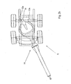
Figure 3 is a schematic side view of the coupling device according tofigure 1 (in the neutral position); -
Figures 4a and4b are schematic bottom plan views of the coupling device offigure 1 , which show said device in the neutral position and in the non-neutral position, respectively; -
Figure 5 is a schematic top plan view of the vehicle combination offigure 1 during a turn; -
Figures 6a and6b are schematic bottom plan views of a second preferred embodiment of a coupling device according to the invention, which show said device in the neutral position and in the non-neutral position, respectively; and -
Figure 7 is a schematic side view of the coupling device according tofigure 6a (in the neutral position thereof). - The various parts are shown in transparent view in the figures, so that the parts positioned behind said parts are also shown.
-
Figure 1 shows avehicle combination 1, more specifically a tractor-trailer combination, the tractor being configured as atruck 2 and the trailer being configured as a three-axled trailer. Thetrailer 3 is coupled to thetruck 2 by means of a coupling device, hereinafter calleddolly 4. -
Figures 2a ,3 and4a show thedolly 4 in more detail. Thedolly 4 comprises aframe 5 withlongitudinal girders cross beams dolly 4 further comprises twowheel pairs wheels drawbar assembly 10, which is at least substantially made up of adrawbar member 11 at the front of theframe 5, adrawbar disc 12 and a coupling member 13 (also refer tofigure 3 ), which forms the connection between the drawbar member and thedrawbar disc 12. - The
drawbar member 11 has a cranked shape, seen in the vertical plane, and is provided with acoupling eye 14 at the front side, which is to mate with a coupling pin (not shown in detail) forming part of thetruck 2 at the rear side thereof. When thetruck 2 and thedrawbar member 11 are coupled in this manner, they can pivot relative to each other about avertical pivot axis 15 extending through the centre of thecoupling eye 14. - The
drawbar disc 12 is substantially disc-shaped, the diameter of which disc shape being substantially equal to the width of theframe 5. At its rear side, the disc shape of the drawbar plate blends into a projectingstop edge 16 between therear wheels drawbar disc 12, and thus theentire drawbar assembly 10, is pivotally supported about thevertical pivot axis 17 with respect to theframe 5. To enable said pivoting, thedolly 4 is provided with a horizontal guide 18, which substantially comprises twoarcuate guide plates coupling member 13 is positioned for guiding cooperation with the upper side and the bottom side, respectively, of thecoupling member 13. - The
dolly 4 furthermore comprises acoupling plate 19 provided with a wedge-shaped slot 20, which is disposed above thedrawbar disc 12. Via saidcoupling plate 19, thetrailer 3 can be coupled with thedolly 4, with a pin (not shown), usually referred to as kingpin, being retained in the front end of theslot 20 by means of a safety catch. Such a connection enables thetrailer 3 to pivot about thevertical pivot axis 21, which coincides with the central axis of the kingpin, with respect to thecoupling plate 19 and/or to pivot jointly with thecoupling plate 19 about saidvertical pivot axis 21 with respect to theframe 5. Thevertical pivot axis 21 coincides with thevertical pivot axis 17 for thedrawbar assembly 10. Thecoupling plate 19 is in principle rigidly connected either to theframe 5 or to thedrawbar disc 12, but it may also be pivotally connected to theframe 5 or to thedrawbar disc 12 about a pivot axis that coincides with thepivot axis 21. - At the bottom side, the
dolly 4 is provided with a steering mechanism for steering thefront wheels drawbar assembly 10 about thepivot axis 17 with respect to theframe 5. The steering mechanism is shown infigures 4a and4b , and the operation of said mechanism will become clear upon comparingfigures 4a and4b . In order of kinematic structure, the steering mechanism comprises: a slidingrod 24 which is movable in its longitudinal direction within a slidingmember 25, steeringrods composite transmission element 27,track rods steering levers respective wheels member 25 is pivotally supported (together with the sliding rod 24) with respect to theframe 5 about avertical axis 30. At its front end, the slidingrod 24 is pivotally connected to thedrawbar disc 12 about apivot axis 23. Thesteering rods member 25 and thetransmission element 27 at their ends. Thetrack rods steering levers transmission element 27 at the opposite end. Thetransmission element 27 is pivotally supported about avertical pivot axis 31 with respect to theframe 5. -
Figure 5 shows how avehicle combination 1 takes a turn, more specifically it shows the pivoted positions which thetruck 1, thedrawbar assembly 10, theframe 5 and the trailer successively take up with respect to each other. The figure also shows how thefront wheels figures 4a and4b . Because of the aforesaid pivoted positions, thevehicle combination 1 has a comparatively small turning circle, which effect is enhanced by the steeredfront wheels trailer 3 will exhibit a stronger tendency to track well behind thetruck 2. - The latter effect is further enhanced by using two
cylinders stop edge 16. At their end remote from the stop edge, thecylinders longitudinal girders frame 5. At the other end, thecylinders stop edge 16 that faces towards thecylinder drawbar assembly 10 that is shown infigure 2a . As soon as pivoting of thedrawbar assembly 10 about thepivot axis 17 with respect to theframe 5 causes the drawbar assembly to move to a position different from said neutral position, which happens when swerving or taking a turn, for example, one of thecylinders cylinder 32a infigure 2b ) is made to contract, with thecylinder cylinder drawbar assembly 10 back to its neutral position again. The length of theother cylinder cylinder 32b infigure 2b ) does not change, and consequently said cylinder does not exert a force that opposes the pivoting of thedrawbar assembly 10 from the neutral position. The action of thecylinders drawbar assembly 10 after thevehicle combination 1 has taken a turn. - Alternatively it is also possible within the framework of the present invention to generate the reset force mechanically rather than hydraulically/pneumatically by substituting the
cylinders longitudinal girders cylinders stop edge 16 at their other end. Depending on any bias in the springs, which bias is present in the neutral position of thedrawbar assembly 10, the spring tension (tension or compression) is used to induce thedrawbar assembly 10 to take up its neutral position again. - It stands to reason that the forces that are exerted on the
drawbar assembly 10 within the framework of the present invention to make the drawbar assembly return to its neutral position are not so large that they make it more difficult to take turns, or in general interfere with the movement of thedrawbar assembly 10 in a direction away from the neutral position at moments when this is desirable. On the other hand, said forces must be large enough to have a noticeable accelerating effect on the return of thedrawbar assembly 10 from a non-neutral position to the neutral position. - To make it easier to reverse the
vehicle combination 1, it is advantageous if thedrawbar assembly 10 can be locked in the neutral position, for example by using a pin-hole coupling as described inEP-A2-1 466 813 . Alternatively it is also possible, however, to use thecylinders -
Figures 6a-7 relate to adolly 51 according to a second preferred embodiment of the invention. Thedolly 51 is to a large extent identical to thedolly 4. Consequently, corresponding parts are indicated by the same numerals for easy reference. For a more detailed explanation of the parts in question, reference is made to the preceding description of thedolly 4. - The
dolly 51 and thedolly 4 are different from each other in that different measures have been taken to ensure that asemitrailer 3 will track well behind atruck 2 also after taking a turn. As is the case with thedolly 4, the pivot axes 17 and 21 coincide with thedolly 51. Thedolly 51, on the other hand, does not usecylinders stop edge 16, as is the case with thedolly 4, but it makes use of air bellows 52a, 52b. The air bellows 52a, 52b, which are known to those skilled in the art, comprise apot body body truck 2, with a pressure of, for example, about 5 bar prevailing in the air bellows 52a, 52b during normal use. In a neutral position as shown infigure 6a , thepot bodies bellows bodies 54a, 54 along a limited portion of their axial length. Thebellows bodies steel mounting plate plates cross beam 56, which extends between the rear ends of thelongitudinal girders - On the side of the air bellows 52a, 52b remote from the mounting
plates coupling rods pot bodies coupling rods holes - The
drawbar disc 59, which does not have a stop edge such as thestop edge 16 of thedrawbar disc 12, is provided with twopivot pins drawbar disc 59 into the respective slottedholes holes coupling rods drawbar disc 59 via the pivot pins 60a, 60b extending within the slottedholes coupling rods - When taking a turn, as shown in
figure 6b , thepivot pin holes holes drawbar member 11 thepivot pin hole pivot pin dolly 51 upon pivoting of thedrawbar disc 59, as a result of which the associatedpot body body respective bellows body - The
pivot pin case pivot pin 60b) will push thecoupling rod 57b in the direction of the air bellows 52b, as a result of which thepot body 53b is pushed into thebellows body 54b at a slightly skewed angle. This causes the pneumatic volume of thebellows body 54b to decrease significantly, as a result of which the pressure in the air bellows 52b is increased and consequently an increased resistance develops to push thepivot pin 60b back again, so that thedrawbar member 11 will assume its neutral position again. As is the case with thedolly 4, where only onecylinder dolly 51 is operative when taking a turn. - To control the movement of the
pot bodies dolly 51 is furthermore provided with guide rods. In the case of thepot body 53b this is theguide rod 61, which extends within the height of thelongitudinal girder cross beam 7c about a vertical pivot axis 81. In the case of thepot body 53a it is theguide rods guide rod 61, respectively, and which are pivotally connected to thecross beam 7c about (aligned) vertical pivot axes 83. At the ends located opposite the pivot axes 82, 83, theguide rods pot body
Claims (10)
- A device (4) for coupling a towed vehicle (3) to a towing vehicle (2), comprising a frame (5), at least one wheel pair (8) for moving the device, the wheels of said at least one wheel pair being of the steering type, a drawbar assembly (10) which can be pivotally coupled to the towing vehicle about a first vertical pivot axis (15) on the one hand and which is pivotally connected to the frame about a second vertical pivot axis (17) on the other hand, as well as a coupling plate (19) for pivotally coupling the towed vehicle to the device about a third vertical pivot axis (21), in which device means are provided for causing the wheels of the steering type to be steered in dependence on the pivoted position of the drawbar assembly about the second vertical pivot axis with respect to the frame, characterised in that reset means (32a, 32b; 52a, 52b) are provided, which reset means act between the frame and the drawbar assembly and act directly on the drawbar assembly for causing the drawbar assembly to pivot back about the second vertical axis from a non-neutral position to a neutral position.
- A device according to claim 1, characterised in that the reset means comprise at least one cylinder (32a, 32b).
- A device according to claim 2, characterised in that the reset means comprise at least two cylinders acting in opposite directions.
- A device according to claim 3, characterised in that only one of said at least two cylinders acts between the frame and the drawbar assembly in a non-neutral position.
- A device according to any one of the preceding claims, characterised in that the reset means operate on the basis of pneumatic pressure.
- A device according to any one of the preceding claims, characterised in that the reset means comprise an air bellows (52a, 52b)
- A device according to any one of the preceding claims, characterised in that the reset means comprise at least one rod (57a, 57b) which is pivotally connected to the drawbar assembly by means of a pin-slot connection.
- A device according to any one of the preceding claims. characterised in that locking means are provided for locking the drawbar assembly in the neutral position.
- A device according to any one of the preceding claims, characterised in that the second vertical pivot axis and the third vertical pivot axis coincide.
- A vehicle combination comprising a towing vehicle, a towed vehicle and a coupling device for coupling the towed vehicle to the towing vehicle, characterised in that said coupling device is configured as defined in any one of the preceding claims.
Applications Claiming Priority (1)
| Application Number | Priority Date | Filing Date | Title |
|---|---|---|---|
| NL1032472A NL1032472C2 (en) | 2006-09-11 | 2006-09-11 | Device for coupling a towing vehicle and a towed vehicle and a vehicle combination. |
Publications (2)
| Publication Number | Publication Date |
|---|---|
| EP1897790A1 EP1897790A1 (en) | 2008-03-12 |
| EP1897790B1 true EP1897790B1 (en) | 2010-03-17 |
Family
ID=37898599
Family Applications (1)
| Application Number | Title | Priority Date | Filing Date |
|---|---|---|---|
| EP07017462A Not-in-force EP1897790B1 (en) | 2006-09-11 | 2007-09-06 | Device for coupling a towed vehicle to a towing vehicle, as well as a vehicle combination |
Country Status (4)
| Country | Link |
|---|---|
| EP (1) | EP1897790B1 (en) |
| AT (1) | ATE461100T1 (en) |
| DE (1) | DE602007005315D1 (en) |
| NL (1) | NL1032472C2 (en) |
Cited By (3)
| Publication number | Priority date | Publication date | Assignee | Title |
|---|---|---|---|---|
| US11668234B1 (en) * | 2022-03-23 | 2023-06-06 | Enerset Electric Ltd. | High density mobile power unit and system |
| US12104523B2 (en) * | 2022-03-23 | 2024-10-01 | Enerset Electric Ltd. | High density mobile power unit and system |
| US12172722B2 (en) * | 2022-03-23 | 2024-12-24 | Enerset Electric Ltd. | High density horsepower mobile pump system |
Families Citing this family (4)
| Publication number | Priority date | Publication date | Assignee | Title |
|---|---|---|---|---|
| DE102006044206A1 (en) * | 2006-09-15 | 2008-03-27 | Fahrzeugwerk Bernard Krone Gmbh | Dolly axle |
| ES2528135T3 (en) * | 2012-02-29 | 2015-02-04 | Helmut Fliegl | Auxiliary axle for semi-trailers |
| PL3398842T3 (en) | 2017-05-04 | 2021-07-12 | Helmut Fliegl | Dolly for semitrailers |
| DE102018121205B4 (en) * | 2018-08-30 | 2020-12-17 | H & W Nutzfahrzeugtechnik Gmbh | Dolly reduction axis |
Family Cites Families (4)
| Publication number | Priority date | Publication date | Assignee | Title |
|---|---|---|---|---|
| CA1183182A (en) * | 1982-11-23 | 1985-02-26 | John K. Lesarge | Dolly for a semitrailer |
| SE446844B (en) * | 1983-04-29 | 1986-10-13 | Jarlsson Assar Karl Johan | COUNTRY SVEG STAG |
| US6450523B1 (en) * | 1999-11-23 | 2002-09-17 | Nathan E. Masters | Steering method for a trailing section of an articulated vehicle |
| DE20305794U1 (en) | 2003-04-10 | 2003-07-10 | Fahrzeugwerk Bernard Krone GmbH, 49757 Werlte | Dolly axle with steerable wheelset |
-
2006
- 2006-09-11 NL NL1032472A patent/NL1032472C2/en not_active IP Right Cessation
-
2007
- 2007-09-06 DE DE602007005315T patent/DE602007005315D1/en active Active
- 2007-09-06 EP EP07017462A patent/EP1897790B1/en not_active Not-in-force
- 2007-09-06 AT AT07017462T patent/ATE461100T1/en not_active IP Right Cessation
Cited By (3)
| Publication number | Priority date | Publication date | Assignee | Title |
|---|---|---|---|---|
| US11668234B1 (en) * | 2022-03-23 | 2023-06-06 | Enerset Electric Ltd. | High density mobile power unit and system |
| US12104523B2 (en) * | 2022-03-23 | 2024-10-01 | Enerset Electric Ltd. | High density mobile power unit and system |
| US12172722B2 (en) * | 2022-03-23 | 2024-12-24 | Enerset Electric Ltd. | High density horsepower mobile pump system |
Also Published As
| Publication number | Publication date |
|---|---|
| NL1032472C2 (en) | 2008-03-12 |
| EP1897790A1 (en) | 2008-03-12 |
| DE602007005315D1 (en) | 2010-04-29 |
| ATE461100T1 (en) | 2010-04-15 |
Similar Documents
| Publication | Publication Date | Title |
|---|---|---|
| EP1897790B1 (en) | Device for coupling a towed vehicle to a towing vehicle, as well as a vehicle combination | |
| EP0007749B1 (en) | Self-steering dolly for releasable connection of semi-trailers in tandem | |
| AU2002223009B2 (en) | Articulated vehicle wheel tracking mechanism | |
| US4720119A (en) | Steering system for a four-wheeled trailer | |
| CA2688205C (en) | Steering system for road transport vehicles | |
| US7694993B2 (en) | Trailer steering mechanism | |
| US4768802A (en) | Controlled steering dolly for a truck trailer | |
| US6135484A (en) | Tow bar construction for transport vehicles and transport vehicle combinations, and a transport vehicle combination | |
| CS254307B2 (en) | Control device for multiaxle trailers with lenghthening piece | |
| US3591203A (en) | Hydraulic automatic steering arrangement for pulled vehicles | |
| EP1900610B1 (en) | Dolly axle | |
| CN111163998A (en) | Hitchable road motor vehicle with compact steering and suspension | |
| CA2507556A1 (en) | A trailer for towing after a towing vehicle, a system comprising a trailer and a towing vehicle, and a method of steering a trailer around a turning point | |
| WO2015148468A1 (en) | Steering lock mechanism for heavy-duty vehicle axle/suspension system | |
| EP1557305A1 (en) | Vehicle trailer | |
| US4579362A (en) | Laterally yieldable hitch pole for trailing vehicles | |
| US3993326A (en) | Vehicle with self-steering trailer | |
| US4598926A (en) | Asymmetrical four-bar link trailer hitch | |
| US4902030A (en) | Short hitch with variable geometry and linkage support bearings movable in a circular arc for so-called balanced trailers and semi-trailers | |
| US3352374A (en) | Trailer tractor | |
| US8011684B2 (en) | Trailer towing-control apparatus | |
| DE4214790A1 (en) | Deactivatable axle steering esp for load transport vehicle at rear axle - has at least one adjusting element such as hydraulic cylinder fixed at one end to chassis and at other end to component determining steering lock of axle to be deflected. | |
| US2431626A (en) | Short turn trailer vehicle |
Legal Events
| Date | Code | Title | Description |
|---|---|---|---|
| PUAI | Public reference made under article 153(3) epc to a published international application that has entered the european phase |
Free format text: ORIGINAL CODE: 0009012 |
|
| AK | Designated contracting states |
Kind code of ref document: A1 Designated state(s): AT BE BG CH CY CZ DE DK EE ES FI FR GB GR HU IE IS IT LI LT LU LV MC MT NL PL PT RO SE SI SK TR |
|
| AX | Request for extension of the european patent |
Extension state: AL BA HR MK YU |
|
| 17P | Request for examination filed |
Effective date: 20080905 |
|
| 17Q | First examination report despatched |
Effective date: 20081023 |
|
| AKX | Designation fees paid |
Designated state(s): AT BE BG CH CY CZ DE DK EE ES FI FR GB GR HU IE IS IT LI LT LU LV MC MT NL PL PT RO SE SI SK TR |
|
| GRAP | Despatch of communication of intention to grant a patent |
Free format text: ORIGINAL CODE: EPIDOSNIGR1 |
|
| GRAS | Grant fee paid |
Free format text: ORIGINAL CODE: EPIDOSNIGR3 |
|
| GRAA | (expected) grant |
Free format text: ORIGINAL CODE: 0009210 |
|
| AK | Designated contracting states |
Kind code of ref document: B1 Designated state(s): AT BE BG CH CY CZ DE DK EE ES FI FR GB GR HU IE IS IT LI LT LU LV MC MT NL PL PT RO SE SI SK TR |
|
| REG | Reference to a national code |
Ref country code: GB Ref legal event code: FG4D |
|
| REG | Reference to a national code |
Ref country code: CH Ref legal event code: EP |
|
| REG | Reference to a national code |
Ref country code: IE Ref legal event code: FG4D |
|
| REF | Corresponds to: |
Ref document number: 602007005315 Country of ref document: DE Date of ref document: 20100429 Kind code of ref document: P |
|
| REG | Reference to a national code |
Ref country code: NL Ref legal event code: T3 |
|
| PG25 | Lapsed in a contracting state [announced via postgrant information from national office to epo] |
Ref country code: LT Free format text: LAPSE BECAUSE OF FAILURE TO SUBMIT A TRANSLATION OF THE DESCRIPTION OR TO PAY THE FEE WITHIN THE PRESCRIBED TIME-LIMIT Effective date: 20100317 |
|
| LTIE | Lt: invalidation of european patent or patent extension |
Effective date: 20100317 |
|
| PG25 | Lapsed in a contracting state [announced via postgrant information from national office to epo] |
Ref country code: SI Free format text: LAPSE BECAUSE OF FAILURE TO SUBMIT A TRANSLATION OF THE DESCRIPTION OR TO PAY THE FEE WITHIN THE PRESCRIBED TIME-LIMIT Effective date: 20100317 Ref country code: PL Free format text: LAPSE BECAUSE OF FAILURE TO SUBMIT A TRANSLATION OF THE DESCRIPTION OR TO PAY THE FEE WITHIN THE PRESCRIBED TIME-LIMIT Effective date: 20100317 Ref country code: LV Free format text: LAPSE BECAUSE OF FAILURE TO SUBMIT A TRANSLATION OF THE DESCRIPTION OR TO PAY THE FEE WITHIN THE PRESCRIBED TIME-LIMIT Effective date: 20100317 Ref country code: FI Free format text: LAPSE BECAUSE OF FAILURE TO SUBMIT A TRANSLATION OF THE DESCRIPTION OR TO PAY THE FEE WITHIN THE PRESCRIBED TIME-LIMIT Effective date: 20100317 Ref country code: AT Free format text: LAPSE BECAUSE OF FAILURE TO SUBMIT A TRANSLATION OF THE DESCRIPTION OR TO PAY THE FEE WITHIN THE PRESCRIBED TIME-LIMIT Effective date: 20100317 |
|
| PG25 | Lapsed in a contracting state [announced via postgrant information from national office to epo] |
Ref country code: GR Free format text: LAPSE BECAUSE OF FAILURE TO SUBMIT A TRANSLATION OF THE DESCRIPTION OR TO PAY THE FEE WITHIN THE PRESCRIBED TIME-LIMIT Effective date: 20100618 Ref country code: SE Free format text: LAPSE BECAUSE OF FAILURE TO SUBMIT A TRANSLATION OF THE DESCRIPTION OR TO PAY THE FEE WITHIN THE PRESCRIBED TIME-LIMIT Effective date: 20100317 Ref country code: CY Free format text: LAPSE BECAUSE OF FAILURE TO SUBMIT A TRANSLATION OF THE DESCRIPTION OR TO PAY THE FEE WITHIN THE PRESCRIBED TIME-LIMIT Effective date: 20100317 Ref country code: ES Free format text: LAPSE BECAUSE OF FAILURE TO SUBMIT A TRANSLATION OF THE DESCRIPTION OR TO PAY THE FEE WITHIN THE PRESCRIBED TIME-LIMIT Effective date: 20100628 Ref country code: RO Free format text: LAPSE BECAUSE OF FAILURE TO SUBMIT A TRANSLATION OF THE DESCRIPTION OR TO PAY THE FEE WITHIN THE PRESCRIBED TIME-LIMIT Effective date: 20100317 Ref country code: EE Free format text: LAPSE BECAUSE OF FAILURE TO SUBMIT A TRANSLATION OF THE DESCRIPTION OR TO PAY THE FEE WITHIN THE PRESCRIBED TIME-LIMIT Effective date: 20100317 |
|
| PG25 | Lapsed in a contracting state [announced via postgrant information from national office to epo] |
Ref country code: CZ Free format text: LAPSE BECAUSE OF FAILURE TO SUBMIT A TRANSLATION OF THE DESCRIPTION OR TO PAY THE FEE WITHIN THE PRESCRIBED TIME-LIMIT Effective date: 20100317 Ref country code: IS Free format text: LAPSE BECAUSE OF FAILURE TO SUBMIT A TRANSLATION OF THE DESCRIPTION OR TO PAY THE FEE WITHIN THE PRESCRIBED TIME-LIMIT Effective date: 20100717 Ref country code: SK Free format text: LAPSE BECAUSE OF FAILURE TO SUBMIT A TRANSLATION OF THE DESCRIPTION OR TO PAY THE FEE WITHIN THE PRESCRIBED TIME-LIMIT Effective date: 20100317 Ref country code: BG Free format text: LAPSE BECAUSE OF FAILURE TO SUBMIT A TRANSLATION OF THE DESCRIPTION OR TO PAY THE FEE WITHIN THE PRESCRIBED TIME-LIMIT Effective date: 20100617 |
|
| PLBE | No opposition filed within time limit |
Free format text: ORIGINAL CODE: 0009261 |
|
| STAA | Information on the status of an ep patent application or granted ep patent |
Free format text: STATUS: NO OPPOSITION FILED WITHIN TIME LIMIT |
|
| PG25 | Lapsed in a contracting state [announced via postgrant information from national office to epo] |
Ref country code: DK Free format text: LAPSE BECAUSE OF FAILURE TO SUBMIT A TRANSLATION OF THE DESCRIPTION OR TO PAY THE FEE WITHIN THE PRESCRIBED TIME-LIMIT Effective date: 20100317 Ref country code: PT Free format text: LAPSE BECAUSE OF FAILURE TO SUBMIT A TRANSLATION OF THE DESCRIPTION OR TO PAY THE FEE WITHIN THE PRESCRIBED TIME-LIMIT Effective date: 20100719 |
|
| 26N | No opposition filed |
Effective date: 20101220 |
|
| PG25 | Lapsed in a contracting state [announced via postgrant information from national office to epo] |
Ref country code: IT Free format text: LAPSE BECAUSE OF FAILURE TO SUBMIT A TRANSLATION OF THE DESCRIPTION OR TO PAY THE FEE WITHIN THE PRESCRIBED TIME-LIMIT Effective date: 20100317 |
|
| PG25 | Lapsed in a contracting state [announced via postgrant information from national office to epo] |
Ref country code: MC Free format text: LAPSE BECAUSE OF NON-PAYMENT OF DUE FEES Effective date: 20100930 |
|
| REG | Reference to a national code |
Ref country code: FR Ref legal event code: ST Effective date: 20110531 |
|
| PG25 | Lapsed in a contracting state [announced via postgrant information from national office to epo] |
Ref country code: IE Free format text: LAPSE BECAUSE OF NON-PAYMENT OF DUE FEES Effective date: 20100906 Ref country code: FR Free format text: LAPSE BECAUSE OF NON-PAYMENT OF DUE FEES Effective date: 20100930 |
|
| PG25 | Lapsed in a contracting state [announced via postgrant information from national office to epo] |
Ref country code: MT Free format text: LAPSE BECAUSE OF FAILURE TO SUBMIT A TRANSLATION OF THE DESCRIPTION OR TO PAY THE FEE WITHIN THE PRESCRIBED TIME-LIMIT Effective date: 20100317 |
|
| REG | Reference to a national code |
Ref country code: CH Ref legal event code: PL |
|
| GBPC | Gb: european patent ceased through non-payment of renewal fee |
Effective date: 20110906 |
|
| PG25 | Lapsed in a contracting state [announced via postgrant information from national office to epo] |
Ref country code: CH Free format text: LAPSE BECAUSE OF NON-PAYMENT OF DUE FEES Effective date: 20110930 Ref country code: LI Free format text: LAPSE BECAUSE OF NON-PAYMENT OF DUE FEES Effective date: 20110930 |
|
| PG25 | Lapsed in a contracting state [announced via postgrant information from national office to epo] |
Ref country code: GB Free format text: LAPSE BECAUSE OF NON-PAYMENT OF DUE FEES Effective date: 20110906 |
|
| PG25 | Lapsed in a contracting state [announced via postgrant information from national office to epo] |
Ref country code: LU Free format text: LAPSE BECAUSE OF NON-PAYMENT OF DUE FEES Effective date: 20100906 Ref country code: HU Free format text: LAPSE BECAUSE OF FAILURE TO SUBMIT A TRANSLATION OF THE DESCRIPTION OR TO PAY THE FEE WITHIN THE PRESCRIBED TIME-LIMIT Effective date: 20100918 |
|
| PG25 | Lapsed in a contracting state [announced via postgrant information from national office to epo] |
Ref country code: TR Free format text: LAPSE BECAUSE OF FAILURE TO SUBMIT A TRANSLATION OF THE DESCRIPTION OR TO PAY THE FEE WITHIN THE PRESCRIBED TIME-LIMIT Effective date: 20100317 |
|
| PGFP | Annual fee paid to national office [announced via postgrant information from national office to epo] |
Ref country code: NL Payment date: 20190918 Year of fee payment: 13 Ref country code: DE Payment date: 20190918 Year of fee payment: 13 |
|
| PGFP | Annual fee paid to national office [announced via postgrant information from national office to epo] |
Ref country code: BE Payment date: 20190918 Year of fee payment: 13 |
|
| REG | Reference to a national code |
Ref country code: DE Ref legal event code: R119 Ref document number: 602007005315 Country of ref document: DE |
|
| REG | Reference to a national code |
Ref country code: NL Ref legal event code: MM Effective date: 20201001 |
|
| REG | Reference to a national code |
Ref country code: BE Ref legal event code: MM Effective date: 20200930 |
|
| PG25 | Lapsed in a contracting state [announced via postgrant information from national office to epo] |
Ref country code: NL Free format text: LAPSE BECAUSE OF NON-PAYMENT OF DUE FEES Effective date: 20201001 |
|
| PG25 | Lapsed in a contracting state [announced via postgrant information from national office to epo] |
Ref country code: DE Free format text: LAPSE BECAUSE OF NON-PAYMENT OF DUE FEES Effective date: 20210401 |
|
| PG25 | Lapsed in a contracting state [announced via postgrant information from national office to epo] |
Ref country code: BE Free format text: LAPSE BECAUSE OF NON-PAYMENT OF DUE FEES Effective date: 20200930 |