EP1897787B1 - Car body frame member - Google Patents
Car body frame member Download PDFInfo
- Publication number
- EP1897787B1 EP1897787B1 EP07017506A EP07017506A EP1897787B1 EP 1897787 B1 EP1897787 B1 EP 1897787B1 EP 07017506 A EP07017506 A EP 07017506A EP 07017506 A EP07017506 A EP 07017506A EP 1897787 B1 EP1897787 B1 EP 1897787B1
- Authority
- EP
- European Patent Office
- Prior art keywords
- car body
- body frame
- frame member
- front side
- bent portion
- Prior art date
- Legal status (The legal status is an assumption and is not a legal conclusion. Google has not performed a legal analysis and makes no representation as to the accuracy of the status listed.)
- Active
Links
- 239000011324 bead Substances 0.000 claims description 22
- 230000003014 reinforcing effect Effects 0.000 claims description 14
- 238000009751 slip forming Methods 0.000 claims description 6
- 230000002411 adverse Effects 0.000 description 1
- 238000005452 bending Methods 0.000 description 1
- 238000007796 conventional method Methods 0.000 description 1
- 238000010586 diagram Methods 0.000 description 1
- 230000002708 enhancing effect Effects 0.000 description 1
- 230000002787 reinforcement Effects 0.000 description 1
Images

Classifications
-
- B—PERFORMING OPERATIONS; TRANSPORTING
- B62—LAND VEHICLES FOR TRAVELLING OTHERWISE THAN ON RAILS
- B62D—MOTOR VEHICLES; TRAILERS
- B62D21/00—Understructures, i.e. chassis frame on which a vehicle body may be mounted
- B62D21/15—Understructures, i.e. chassis frame on which a vehicle body may be mounted having impact absorbing means, e.g. a frame designed to permanently or temporarily change shape or dimension upon impact with another body
- B62D21/152—Front or rear frames
Definitions
- the present invention relates to a car body frame member according to the preamble part of claim 1.
- Japanese Patent Application Laid-open No. 2005-199751 discloses a body frame member according to the preamble part of claim 1.
- Said conventional front side member as a car body frame member extends in a longitudinal direction of a vehicle on opposite sides in a widthwise direction of the vehicle of a front portion of the car body (e.g., an engine room).
- a rear portion of the front side member is continuously connected to an extension member extending downward along a dash panel lower.
- a portion of the front side member connected to an extension member is a smoothly inclining bent portion.
- a bead is continuously formed in a height direction on a substantially central portion of a side surface of the front side member in the height direction, and the rigidity of the member is enhanced by the bead.
- the bead that is formed in a length direction of the side surface is discontinued at a location before the front side member is connected to the extension member, i.e., at a rear portion of a straight portion of the front side member.
- the straight portion when a collision load is applied from a front portion of the front side member, since the straight portion is formed with the bead, the straight portion can secure sufficient rigidity.
- the bent portion connected to the extension member is not formed with the bead, the cross-sectional proof stress of the bent portion is lowered and it is difficult for the bent portion to secure a necessary flexural rigidity although a great bending moment is applied to the bent portion.
- GB 2 326 853 A is related to a reinforcement for a motor vehicle structure having a side frame. Reinforcing members are spot-welded to said side frame in order to reinforce a bend of said side frame.
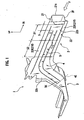
- Fig. 1 is a perspective view showing an assembled state of a car body frame member.
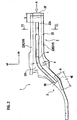
- Fig. 2 is a side view of the car body frame member.
- FR represents vehicle front, and UP represents an upward direction.
- the car body frame member 1 is a connecting portion between a front side member 2 and an extension member 3.
- the front side member 2 straightly extends in a longitudinal direction of the vehicle on opposite sides of a front portion of a car body in a widthwise direction of the vehicle.
- the front side member 2 corresponds to a straight portion.
- a collision load from front is applied in an extending direction of the front side member 2 from a front portion of the front side member 2.
- the extension member 3 is coupled to a rear portion (left side in Fig. 2 ) of the front side member 2.
- the extension member 3 is downwardly inclined along a lower side of a dash panel lower (not shown) .
- the rear portion (left side in Fig. 2 ) of the extension member 3 is located below the front portion.
- a portion of the frame extending from the rear portion of the front side member 2 to the extension member 3 is a bent portion 4.
- the bent portion 4 is smoothly curved downward, i.e., inclined in a direction intersecting with an application direction of the collision load.
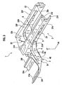
- Fig. 3 is an exploded perspective view of the car body frame member.
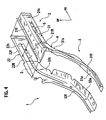
- Fig. 4 is an exploded perspective view of the car body frame member as viewed from rear of the vehicle.
- Fig. 5 is an end view as viewed from a direction A in Fig. 2 .
- Fig. 6 is a sectional view taken along a line VI-VI in Fig. 2 .
- the front side member 2 includes a side member inner plate 21 having a substantially hat-like cross section, and a side member outer plate 22 having a substantially flat band-like shape.
- the side member inner plate 21 and the side member outer plate 22 are bonded to each other.
- the side member inner plate 21 is provided at its upper and lower ends with flanges 21f.
- the side member outer plate 22 is provided at its upper and lower ends with flanges 22f.
- the side member inner plate 21 and the side member outer plate 22 constitute a closed cross section structure by bonding the flanges 21f and 22f to each other as shown in Figs. 5 and 6 .
- the car body frame member 1 disposed on the starboard side of the vehicle is shown in Figs. 1 and 2
- the car body frame member 1 disposed on the port side of the car body is shown in Figs. 3 and 4 .
- the car body frame member 1 disposed on the starboard side and the port side are symmetric to each other with respect to the center line of the car body.
- the extension member 3 includes an extension inner plate 31 and an extension outer plate 32.
- the extension inner plate 31 and the extension outer plate 32 are integrally bonded to rear ends 21R and 22R of the side member inner plate 21 and the side member outer plate 22.
- Front ends 31F and 32F of the extension inner plate 31 and the extension outer plate 32 are continuously connected to the side member inner plate 21 and the side member outer plate 22.
- Cross sections of portions of the front ends 31F and 32F reaching a rear portion of the vehicle are formed into substantially L-shapes by side surfaces 31s and 32s and bottom surfaces 31u and 32u.
- the side surfaces 31s and 32s are connected to side surfaces 21s and 22s of the side member inner plate 21 and the side member outer plate 22.
- the bottom surfaces 31u and 32u are bent from lower sides of the side surfaces 31s and 32s in directions opposed to each other.
- reinforcing beads 5 are formed on side surfaces 21s and 31s as well as 22s and 32s.
- the beads 5 are continuously formed from the front side member 2 that is the straight portion of the car body frame member 1 to the bent portion 4.
- the beads 5 are formed by recessing substantially central portions of both side surfaces 21s and 22s of the front side member 2 and both side surfaces 31s and 32s of the extension member 3 in their height directions inward of the closed cross section.
- the bead 5 is continuously formed from a front portion of the front side member 2, more specifically, from a portion of the front side member 2 retreated from its front end 2F by a predetermined distance S, to a terminal point 4E of the bent portion 4.
- a reinforcing member 6 is provided on a port ion of the extension member 3 corresponding to a forming-terminal portion 5E of the bead 5 formed on the bent portion 4.
- the reinforcing member 6 is coupled such as to cover a lower side of the extension member 3 over an appropriate length L to include a portion corresponding to the forming-terminal portion 5E.
- the reinforcing beads 5 that are continuously formed from the front side member 2 as the straight portion to the bent portion 4 are formed on the side surfaces 21s and 31s as well as 22s and 32s. Therefore, the cross-sectional proof stresses of not only the front side member 2 but also the bent portion 4 can be enhanced. Thus, when a collision load is applied to the front side member 2 from front of the vehicle, the flexural rigidity of the car body frame member 1 including the bent portion 4 can be enhanced with respect to the application of the load (see Fig. 7 ).
- a predetermined section S1 from the front end toward a rear portion of the vehicle is compressed and deformed, a predetermined section S2 located rearward from the predetermined section S1 is not deformed almost at all, and the bent portion 4 existing rearward from the section S2 is bent and deformed.
- Fig. 7 shows flexural rigidity characteristics (shown with a solid line) ⁇ of the car body frame member 1 according to the present embodiment formed with the bead 5, and flexural rigidity characteristics (shown with a broken line) ⁇ as a reference example formed with no bead 5.
- Fig. 7 it can be found that the flexural rigidity of the car body frame member 1 according to the embodiment is enhanced by about 14% as compared with the reference example.
- the car body frame member 1 of the embodiment since the flexural rigidity is enhanced in this manner, the car body frame member 1 can be made thin. More specifically, if the thickness of the front side member 2 is set to 1.4 mm and the thickness of the extension member 3 including the bent portion 4 is set to 2.0 mm, the weight of the car body can be reduced. Thus, the weight of the car body can be reduced.
- the straight portion of the car body frame member 1 is the front side member 2 and in the bent portion 4, the rear portion of the front side member 2 is coupled to the extension member 3.
- the beads 5 are formed in the side surfaces 21s and 22s as well as 31s and 32s at the substantially central portions in the height direction, and the side surfaces are continuously formed on the front side member 2 and the bent portion 4. Therefore, the substantially central portions of the side surfaces 21s and 22s as well as 31s and 32s in the height direction which have weak strength are effectively reinforced, and by forming the beads 5 up to the terminal portion 4E of the bent portion 4, the flexural rigidity from the front side member 2 to the extension member 3 can effectively enhanced.
- the reinforcing member 6 is provided on the portion of the extension member 3 corresponding to the forming-terminal portion 5E of the bead 5 formed in the bent portion 4, the stress concentrated on the forming-terminal portion 5E of the bead 5 can be dispersed through the reinforcing member 6, and the flexural rigidity of the bent portion 4 can further be enhanced.
Description
- The present invention relates to a car body frame member according to the preamble part of
claim 1. - Japanese Patent Application Laid-open No.
2005-199751 US 2005/0151392 A1 , discloses a body frame member according to the preamble part ofclaim 1. Said conventional front side member as a car body frame member extends in a longitudinal direction of a vehicle on opposite sides in a widthwise direction of the vehicle of a front portion of the car body (e.g., an engine room). A rear portion of the front side member is continuously connected to an extension member extending downward along a dash panel lower. A portion of the front side member connected to an extension member is a smoothly inclining bent portion. A bead is continuously formed in a height direction on a substantially central portion of a side surface of the front side member in the height direction, and the rigidity of the member is enhanced by the bead. - However, in this front side member, the bead that is formed in a length direction of the side surface is discontinued at a location before the front side member is connected to the extension member, i.e., at a rear portion of a straight portion of the front side member.
- For this reason, when a collision load is applied from a front portion of the front side member, since the straight portion is formed with the bead, the straight portion can secure sufficient rigidity. However, the bent portion connected to the extension member is not formed with the bead, the cross-sectional proof stress of the bent portion is lowered and it is difficult for the bent portion to secure a necessary flexural rigidity although a great bending moment is applied to the bent portion.
- However, to secure the cross-sectional proof stress of the bent portion, if the thickness of the extension member is increased or a reinforcing member is newly provided, the weight of the car body is adversely increased.
-
GB 2 326 853 A - It is the objective of the present invention to obtain a car body frame member capable of enhancing the cross-sectional proof stress of the bent portion and reducing the weight of the car body.
- According to the present invention, said objective is solved by a car body frame member having the combination of features of
independent claim 1. - Preferred embodiments of the present invention are laid down in the subclaims.
- In the following, the present invention is explained in greater detail by means of embodiments thereof in conjunction with the accompanying drawings, wherein:
-
Fig. 1 is a perspective view showing an assembled state of a car body frame member according to an embodiment; -
Fig. 2 is a side view of the car body frame member according to the embodiment; -
Fig. 3 is an exploded perspective view of the car body frame member according to the embodiment as viewed from front of the vehicle; -
Fig. 4 is an exploded perspective view of the car body frame member according to the embodiment as viewed from rear of the vehicle; -
Fig. 5 is an end view as viewed from a direction A inFig. 2 ; -
Fig. 6 is a sectional view taken along a line VI-VI inFig. 2 ; and -
Fig. 7 is a characteristic diagram showing a flexural rigidity of the car body frame member according to the embodiment in comparison with a conventional technique. - A preferred embodiment will be explained below in detail with reference to the accompanying drawings.
Fig. 1 is a perspective view showing an assembled state of a car body frame member.Fig. 2 is a side view of the car body frame member. In the drawings, FR represents vehicle front, and UP represents an upward direction. - As shown in
Figs. 1 and2 , the carbody frame member 1 according to the embodiment is a connecting portion between afront side member 2 and anextension member 3. - The
front side member 2 straightly extends in a longitudinal direction of the vehicle on opposite sides of a front portion of a car body in a widthwise direction of the vehicle. Thefront side member 2 corresponds to a straight portion. At the time of a head-on collision of the vehicle, a collision load from front is applied in an extending direction of thefront side member 2 from a front portion of thefront side member 2. - The
extension member 3 is coupled to a rear portion (left side inFig. 2 ) of thefront side member 2. Theextension member 3 is downwardly inclined along a lower side of a dash panel lower (not shown) . The rear portion (left side inFig. 2 ) of theextension member 3 is located below the front portion. A portion of the frame extending from the rear portion of thefront side member 2 to theextension member 3 is abent portion 4. Thebent portion 4 is smoothly curved downward, i.e., inclined in a direction intersecting with an application direction of the collision load. -
Fig. 3 is an exploded perspective view of the car body frame member.Fig. 4 is an exploded perspective view of the car body frame member as viewed from rear of the vehicle.Fig. 5 is an end view as viewed from a direction A inFig. 2 .Fig. 6 is a sectional view taken along a line VI-VI inFig. 2 . - As shown in
Figs. 3 and4 , thefront side member 2 includes a side memberinner plate 21 having a substantially hat-like cross section, and a side memberouter plate 22 having a substantially flat band-like shape. The side memberinner plate 21 and the side memberouter plate 22 are bonded to each other. The side memberinner plate 21 is provided at its upper and lower ends withflanges 21f. The side memberouter plate 22 is provided at its upper and lower ends withflanges 22f. The side memberinner plate 21 and the side memberouter plate 22 constitute a closed cross section structure by bonding theflanges Figs. 5 and 6 . - For convenience sake, the car
body frame member 1 disposed on the starboard side of the vehicle is shown inFigs. 1 and2 , and the carbody frame member 1 disposed on the port side of the car body is shown inFigs. 3 and4 . The carbody frame member 1 disposed on the starboard side and the port side are symmetric to each other with respect to the center line of the car body. - Meanwhile, as shown in
Figs. 3 and4 , theextension member 3 includes an extensioninner plate 31 and an extensionouter plate 32. The extensioninner plate 31 and the extensionouter plate 32 are integrally bonded torear ends inner plate 21 and the side memberouter plate 22. -
Front ends inner plate 31 and the extensionouter plate 32 are continuously connected to the side memberinner plate 21 and the side memberouter plate 22. Cross sections of portions of thefront ends side surfaces bottom surfaces side surfaces side surfaces inner plate 21 and the side memberouter plate 22. Thebottom surfaces side surfaces - Upper sides of the
side surfaces inner plate 31 and the extensionouter plate 32 are formed with theflanges flanges - In the present embodiment, reinforcing
beads 5 are formed onside surfaces beads 5 are continuously formed from thefront side member 2 that is the straight portion of the carbody frame member 1 to thebent portion 4. - As shown in
Fig. 6 , thebeads 5 are formed by recessing substantially central portions of bothside surfaces front side member 2 and bothside surfaces extension member 3 in their height directions inward of the closed cross section. As shown inFigs. 1 and2 , thebead 5 is continuously formed from a front portion of thefront side member 2, more specifically, from a portion of thefront side member 2 retreated from itsfront end 2F by a predetermined distance S, to aterminal point 4E of thebent portion 4. - A reinforcing member 6 is provided on a port ion of the
extension member 3 corresponding to a forming-terminal portion 5E of thebead 5 formed on thebent portion 4. The reinforcing member 6 is coupled such as to cover a lower side of theextension member 3 over an appropriate length L to include a portion corresponding to the forming-terminal portion 5E. - According to the car
body frame member 1 of the present embodiment, the reinforcingbeads 5 that are continuously formed from thefront side member 2 as the straight portion to thebent portion 4 are formed on theside surfaces front side member 2 but also thebent portion 4 can be enhanced. Thus, when a collision load is applied to thefront side member 2 from front of the vehicle, the flexural rigidity of the carbody frame member 1 including thebent portion 4 can be enhanced with respect to the application of the load (seeFig. 7 ). - That is, if the collision load F in the extending direction is applied to the car
body frame member 1, as shown inFig. 1 , a predetermined section S1 from the front end toward a rear portion of the vehicle is compressed and deformed, a predetermined section S2 located rearward from the predetermined section S1 is not deformed almost at all, and thebent portion 4 existing rearward from the section S2 is bent and deformed. -
Fig. 7 shows flexural rigidity characteristics (shown with a solid line) α of the carbody frame member 1 according to the present embodiment formed with thebead 5, and flexural rigidity characteristics (shown with a broken line) β as a reference example formed with nobead 5. InFig. 7 , it can be found that the flexural rigidity of the carbody frame member 1 according to the embodiment is enhanced by about 14% as compared with the reference example. - According to the car
body frame member 1 of the embodiment, since the flexural rigidity is enhanced in this manner, the carbody frame member 1 can be made thin. More specifically, if the thickness of thefront side member 2 is set to 1.4 mm and the thickness of theextension member 3 including thebent portion 4 is set to 2.0 mm, the weight of the car body can be reduced. Thus, the weight of the car body can be reduced. - In the present embodiment, the straight portion of the car
body frame member 1 is thefront side member 2 and in thebent portion 4, the rear portion of thefront side member 2 is coupled to theextension member 3. Thebeads 5 are formed in the side surfaces 21s and 22s as well as 31s and 32s at the substantially central portions in the height direction, and the side surfaces are continuously formed on thefront side member 2 and thebent portion 4. Therefore, the substantially central portions of the side surfaces 21s and 22s as well as 31s and 32s in the height direction which have weak strength are effectively reinforced, and by forming thebeads 5 up to theterminal portion 4E of thebent portion 4, the flexural rigidity from thefront side member 2 to theextension member 3 can effectively enhanced. - Since the reinforcing member 6 is provided on the portion of the
extension member 3 corresponding to the forming-terminal portion 5E of thebead 5 formed in thebent portion 4, the stress concentrated on the forming-terminal portion 5E of thebead 5 can be dispersed through the reinforcing member 6, and the flexural rigidity of thebent portion 4 can further be enhanced.
Claims (4)
- A car body frame member (1) comprising:a straight portion having a closed cross section, the straight portion being a front side member (2) configured to extend in longitudinal direction of a vehicle on opposite sides of a front portion of a car body with regard to a widthwise direction of the vehicle,a side surface (21s,22s) of the straight portion being formed with a portion of a reinforcing bead (5), anda bent portion (4) being coupled to a rear portion of the straight portion, said bent portion (4) being continuous with the straight portion and being inclined with respect to the straight portion,characterized in that
a side surface (31s,32s) of the bent portion (4) is formed with another portion of the reinforcing bead (5), and
the portions of the reinforcing bead (5) are continuously formed from the straight portion to the bent portion (4). - A car body frame member (1) according to claim 1, characterized in that the bent portion (4) is a connecting portion between an extension member (3) and a rear portion of the front side member (2).
- A car body frame member (1) according to claim 1 or 2, characterized in that the portions of the reinforcing bead (5) are formed in a substantially central portion of side surfaces (21s,22s,31s,32s) of the front side member (2) and the bent portion (4) in a height direction such as to extend from a front portion of the front side member (2) to a terminal portion (4E) of the bent portion (4).
- A car body frame member (1) according to one of claims 1 to 3, characterized in that a reinforcing member (6) is provided corresponding to a forming-terminal portion (5E) of the reinforcing bead (5).
Applications Claiming Priority (1)
| Application Number | Priority Date | Filing Date | Title |
|---|---|---|---|
| JP2006241847A JP4301269B2 (en) | 2006-09-06 | 2006-09-06 | Member member for vehicle |
Publications (2)
| Publication Number | Publication Date |
|---|---|
| EP1897787A1 EP1897787A1 (en) | 2008-03-12 |
| EP1897787B1 true EP1897787B1 (en) | 2009-12-02 |
Family
ID=38654781
Family Applications (1)
| Application Number | Title | Priority Date | Filing Date |
|---|---|---|---|
| EP07017506A Active EP1897787B1 (en) | 2006-09-06 | 2007-09-06 | Car body frame member |
Country Status (5)
| Country | Link |
|---|---|
| US (1) | US7641270B2 (en) |
| EP (1) | EP1897787B1 (en) |
| JP (1) | JP4301269B2 (en) |
| CN (1) | CN100584680C (en) |
| DE (1) | DE602007003533D1 (en) |
Families Citing this family (23)
| Publication number | Priority date | Publication date | Assignee | Title |
|---|---|---|---|---|
| US8505258B2 (en) * | 2000-08-17 | 2013-08-13 | Industrial Origami, Inc. | Load-bearing three-dimensional structure |
| CN101233286A (en) | 2005-03-17 | 2008-07-30 | 奥里加米工业股份有限公司 | Precision-folded, high strength, fatigue-resistant structures and sheet thereof |
| EP1861317A4 (en) * | 2005-03-25 | 2009-11-18 | Ind Origami Inc | Three-dimensional structure formed with precision fold technology and method of forming same |
| US20080098787A1 (en) | 2006-10-26 | 2008-05-01 | Industrial Origami, Inc. | Method of forming two-dimensional sheet material into three-dimensional structure |
| US8287013B2 (en) * | 2007-11-05 | 2012-10-16 | Toyoda Iron Works Co., Ltd. | Impact absorbing member for vehicle |
| US20090188100A1 (en) * | 2007-12-21 | 2009-07-30 | Industrial Origami, Inc. | Chassis and methods of forming the same |
| CA2715659A1 (en) * | 2008-02-16 | 2009-08-20 | Industrial Origami, Inc. | System for low-force roll folding and methods thereof |
| JP5256979B2 (en) * | 2008-10-06 | 2013-08-07 | 日産自動車株式会社 | Body member structure |
| JP4653210B2 (en) | 2008-11-12 | 2011-03-16 | 本田技研工業株式会社 | Body front structure |
| WO2010093710A1 (en) * | 2009-02-10 | 2010-08-19 | Industrial Origami, Inc. | Sheet of material with bend-controlling structures and method |
| DE112010005328B4 (en) | 2010-03-02 | 2016-01-21 | Toyota Jidosha Kabushiki Kaisha | Vehicle frame member |
| JP5238750B2 (en) * | 2010-05-10 | 2013-07-17 | 本田技研工業株式会社 | Body front structure |
| US8485591B2 (en) | 2010-05-10 | 2013-07-16 | Honda Motor Co., Ltd. | Front vehicle body structure |
| JP2012045995A (en) * | 2010-08-25 | 2012-03-08 | Nissan Motor Co Ltd | Vehicle body structure |
| DE102011103090A1 (en) * | 2011-05-25 | 2012-11-29 | Thyssenkrupp Steel Europe Ag | Vehicle body and its use |
| US8936164B2 (en) | 2012-07-06 | 2015-01-20 | Industrial Origami, Inc. | Solar panel rack |
| KR101394055B1 (en) * | 2013-05-30 | 2014-05-09 | 현대자동차 주식회사 | Bumper cover fixing bracket of automobile |
| JP6344560B2 (en) * | 2014-07-17 | 2018-06-20 | 三菱自動車工業株式会社 | Wheelhouse inner structure |
| JP6102870B2 (en) * | 2014-09-19 | 2017-03-29 | トヨタ自動車株式会社 | Body front structure |
| CN107618589B (en) * | 2017-09-07 | 2019-06-28 | 安徽江淮汽车集团股份有限公司 | A kind of fixed structure of symmetrical bending part |
| US11472244B2 (en) * | 2020-04-16 | 2022-10-18 | Honda Motor Co., Ltd. | Skid plate with recovery point |
| US11766828B2 (en) * | 2020-07-15 | 2023-09-26 | Spirit Aerosystems, Inc. | Method of manufacturing folded structure with additive features |
| CN112429094B (en) * | 2020-11-10 | 2023-03-07 | 东风柳州汽车有限公司 | Cantilever support |
Family Cites Families (10)
| Publication number | Priority date | Publication date | Assignee | Title |
|---|---|---|---|---|
| JPS6116974U (en) | 1984-07-06 | 1986-01-31 | 三菱自動車工業株式会社 | Frame with reinforced structure |
| JP3123584B2 (en) | 1993-12-24 | 2001-01-15 | 日産自動車株式会社 | Body front structure |
| JPH09315344A (en) | 1996-05-28 | 1997-12-09 | Nissan Motor Co Ltd | Chassis and body structure |
| GB2326853B (en) | 1997-06-30 | 2001-08-15 | Daihatsu Motor Co Ltd | Reinforcing structure for substructure of body of automobile |
| JP4193373B2 (en) | 2001-05-14 | 2008-12-10 | トヨタ自動車株式会社 | Hollow structure |
| JP4000951B2 (en) * | 2002-08-13 | 2007-10-31 | 三菱自動車エンジニアリング株式会社 | Auto body front structure |
| JP3970831B2 (en) * | 2003-10-16 | 2007-09-05 | 本田技研工業株式会社 | Auto body structure |
| JP3852445B2 (en) * | 2004-01-13 | 2006-11-29 | 日産自動車株式会社 | Impact energy absorption structure of member members |
| US7380830B2 (en) * | 2005-02-03 | 2008-06-03 | Honda Motor Co., Ltd. | Vehicle front body structure |
| JP4969827B2 (en) | 2005-10-19 | 2012-07-04 | 富士重工業株式会社 | Body front structure |
-
2006
- 2006-09-06 JP JP2006241847A patent/JP4301269B2/en active Active
-
2007
- 2007-09-05 US US11/896,694 patent/US7641270B2/en active Active
- 2007-09-06 CN CN200710149541A patent/CN100584680C/en active Active
- 2007-09-06 DE DE602007003533T patent/DE602007003533D1/en active Active
- 2007-09-06 EP EP07017506A patent/EP1897787B1/en active Active
Also Published As
| Publication number | Publication date |
|---|---|
| EP1897787A1 (en) | 2008-03-12 |
| JP4301269B2 (en) | 2009-07-22 |
| CN101138988A (en) | 2008-03-12 |
| US20080054683A1 (en) | 2008-03-06 |
| JP2008062760A (en) | 2008-03-21 |
| DE602007003533D1 (en) | 2010-01-14 |
| CN100584680C (en) | 2010-01-27 |
| US7641270B2 (en) | 2010-01-05 |
Similar Documents
| Publication | Publication Date | Title |
|---|---|---|
| EP1897787B1 (en) | Car body frame member | |
| EP1808362B1 (en) | vehicle body | |
| EP2006191B1 (en) | Vehicle body floor structure | |
| US7950724B2 (en) | Vehicle body rear structure | |
| JP5352682B2 (en) | Body floor structure | |
| US8075047B2 (en) | Automotive vehicle body structure | |
| JP4093104B2 (en) | Auto body structure | |
| US20080252104A1 (en) | Vehicle body rear structure | |
| EP1302389B1 (en) | Rear vehicle body structure | |
| CN109703623B (en) | Vehicle body superstructure | |
| CN110304151B (en) | Front body structure of vehicle | |
| CN111284567B (en) | Vehicle body structure | |
| US7946645B2 (en) | Vehicle body front portion structure | |
| EP3733484B1 (en) | Front body of vehicle | |
| JP4616015B2 (en) | Triangular window reinforcement structure | |
| JPH07187016A (en) | Battery floor structure of electric automobile | |
| CN205345040U (en) | Longeron and have its vehicle | |
| CN213413484U (en) | Support frame and vehicle of sunroof | |
| JPH1016816A (en) | Connecting structure for body frame member | |
| JPH11208520A (en) | Floor cross member reinforcing structure on car body of automobile | |
| CN211223619U (en) | Vehicle B post subassembly and vehicle | |
| JP2000326868A (en) | Front body construction of automobile | |
| JPH08230714A (en) | Cab of motor truck | |
| JP3362387B2 (en) | Roof panel | |
| JPH07164983A (en) | Bumper reinforcement for automobile |
Legal Events
| Date | Code | Title | Description |
|---|---|---|---|
| PUAI | Public reference made under article 153(3) epc to a published international application that has entered the european phase |
Free format text: ORIGINAL CODE: 0009012 |
|
| 17P | Request for examination filed |
Effective date: 20070906 |
|
| AK | Designated contracting states |
Kind code of ref document: A1 Designated state(s): AT BE BG CH CY CZ DE DK EE ES FI FR GB GR HU IE IS IT LI LT LU LV MC MT NL PL PT RO SE SI SK TR |
|
| AX | Request for extension of the european patent |
Extension state: AL BA HR MK YU |
|
| 17Q | First examination report despatched |
Effective date: 20080911 |
|
| AKX | Designation fees paid |
Designated state(s): DE FR GB |
|
| GRAP | Despatch of communication of intention to grant a patent |
Free format text: ORIGINAL CODE: EPIDOSNIGR1 |
|
| GRAS | Grant fee paid |
Free format text: ORIGINAL CODE: EPIDOSNIGR3 |
|
| GRAA | (expected) grant |
Free format text: ORIGINAL CODE: 0009210 |
|
| AK | Designated contracting states |
Kind code of ref document: B1 Designated state(s): DE FR GB |
|
| REG | Reference to a national code |
Ref country code: GB Ref legal event code: FG4D |
|
| REF | Corresponds to: |
Ref document number: 602007003533 Country of ref document: DE Date of ref document: 20100114 Kind code of ref document: P |
|
| PLBE | No opposition filed within time limit |
Free format text: ORIGINAL CODE: 0009261 |
|
| STAA | Information on the status of an ep patent application or granted ep patent |
Free format text: STATUS: NO OPPOSITION FILED WITHIN TIME LIMIT |
|
| 26N | No opposition filed |
Effective date: 20100903 |
|
| REG | Reference to a national code |
Ref country code: FR Ref legal event code: PLFP Year of fee payment: 10 |
|
| REG | Reference to a national code |
Ref country code: FR Ref legal event code: PLFP Year of fee payment: 11 |
|
| REG | Reference to a national code |
Ref country code: FR Ref legal event code: PLFP Year of fee payment: 12 |
|
| REG | Reference to a national code |
Ref country code: DE Ref legal event code: R084 Ref document number: 602007003533 Country of ref document: DE |
|
| REG | Reference to a national code |
Ref country code: GB Ref legal event code: 746 Effective date: 20230928 |
|
| PGFP | Annual fee paid to national office [announced via postgrant information from national office to epo] |
Ref country code: GB Payment date: 20230823 Year of fee payment: 17 |
|
| PGFP | Annual fee paid to national office [announced via postgrant information from national office to epo] |
Ref country code: FR Payment date: 20230822 Year of fee payment: 17 Ref country code: DE Payment date: 20230822 Year of fee payment: 17 |