EP1897715A2 - Stiffening structure and stiffening method for automotive outer panel - Google Patents
Stiffening structure and stiffening method for automotive outer panel Download PDFInfo
- Publication number
- EP1897715A2 EP1897715A2 EP07016124A EP07016124A EP1897715A2 EP 1897715 A2 EP1897715 A2 EP 1897715A2 EP 07016124 A EP07016124 A EP 07016124A EP 07016124 A EP07016124 A EP 07016124A EP 1897715 A2 EP1897715 A2 EP 1897715A2
- Authority
- EP
- European Patent Office
- Prior art keywords
- outer panel
- panel
- annexed
- automotive
- door
- Prior art date
- Legal status (The legal status is an assumption and is not a legal conclusion. Google has not performed a legal analysis and makes no representation as to the accuracy of the status listed.)
- Withdrawn
Links
- 238000000034 method Methods 0.000 title claims description 11
- 239000000853 adhesive Substances 0.000 claims abstract description 12
- 230000001070 adhesive effect Effects 0.000 claims abstract description 12
- 230000002787 reinforcement Effects 0.000 claims description 24
- 239000003973 paint Substances 0.000 claims description 8
- 239000003351 stiffener Substances 0.000 description 43
- 239000013521 mastic Substances 0.000 description 18
- 238000003780 insertion Methods 0.000 description 5
- 230000037431 insertion Effects 0.000 description 5
- 239000011521 glass Substances 0.000 description 2
- 238000013007 heat curing Methods 0.000 description 2
- 230000008878 coupling Effects 0.000 description 1
- 238000010168 coupling process Methods 0.000 description 1
- 238000005859 coupling reaction Methods 0.000 description 1
- 230000000694 effects Effects 0.000 description 1
- 230000002708 enhancing effect Effects 0.000 description 1
- 239000005357 flat glass Substances 0.000 description 1
- 238000012986 modification Methods 0.000 description 1
- 230000004048 modification Effects 0.000 description 1
Images



Classifications
-
- B—PERFORMING OPERATIONS; TRANSPORTING
- B60—VEHICLES IN GENERAL
- B60J—WINDOWS, WINDSCREENS, NON-FIXED ROOFS, DOORS, OR SIMILAR DEVICES FOR VEHICLES; REMOVABLE EXTERNAL PROTECTIVE COVERINGS SPECIALLY ADAPTED FOR VEHICLES
- B60J5/00—Doors
- B60J5/04—Doors arranged at the vehicle sides
- B60J5/042—Reinforcement elements
- B60J5/0422—Elongated type elements, e.g. beams, cables, belts or wires
- B60J5/0423—Elongated type elements, e.g. beams, cables, belts or wires characterised by position in the lower door structure
- B60J5/0426—Elongated type elements, e.g. beams, cables, belts or wires characterised by position in the lower door structure the elements being arranged at the beltline
-
- B—PERFORMING OPERATIONS; TRANSPORTING
- B60—VEHICLES IN GENERAL
- B60J—WINDOWS, WINDSCREENS, NON-FIXED ROOFS, DOORS, OR SIMILAR DEVICES FOR VEHICLES; REMOVABLE EXTERNAL PROTECTIVE COVERINGS SPECIALLY ADAPTED FOR VEHICLES
- B60J5/00—Doors
- B60J5/04—Doors arranged at the vehicle sides
- B60J5/042—Reinforcement elements
- B60J5/0422—Elongated type elements, e.g. beams, cables, belts or wires
- B60J5/0423—Elongated type elements, e.g. beams, cables, belts or wires characterised by position in the lower door structure
- B60J5/043—Elongated type elements, e.g. beams, cables, belts or wires characterised by position in the lower door structure the elements being arranged vertically
-
- B—PERFORMING OPERATIONS; TRANSPORTING
- B60—VEHICLES IN GENERAL
- B60J—WINDOWS, WINDSCREENS, NON-FIXED ROOFS, DOORS, OR SIMILAR DEVICES FOR VEHICLES; REMOVABLE EXTERNAL PROTECTIVE COVERINGS SPECIALLY ADAPTED FOR VEHICLES
- B60J5/00—Doors
- B60J5/04—Doors arranged at the vehicle sides
- B60J5/042—Reinforcement elements
- B60J5/0422—Elongated type elements, e.g. beams, cables, belts or wires
- B60J5/0437—Elongated type elements, e.g. beams, cables, belts or wires characterised by the attachment means to the door, e.g. releasable attachment means
Definitions
- the present invention relates to a stiffening structure and stiffening method for an automotive outer panel, which are configured to reinforce the automotive outer panel by an annexed member arranged on an inner surface of the automotive outer panel while interposing an adhesive therebetween.
- Japanese Utility Model Unexamined Publication No. H4-67514 As a stiffening structure for an automotive outer panel composing an automotive outside, for example, of a door outer panel, there is one described in Japanese Utility Model Unexamined Publication No. H4-67514 (published in 1992).
- the structure in Japanese Utility Model Unexamined Publication No. H4-67514 is one in which an annexed member such as a reinforcement bar is arranged along an inner surface of the door outer panel. This annexed member is partially adhered onto the door outer panel while interposing an adhesive such as a mastic therebetween. Moreover, both ends of the annexed member are supported by attachment pieces joined to the door inner panel.
- both of the ends of the annexed member are individually spot-welded to the attachment pieces. Accordingly, the stiffening structure is prone to cause variations in the vehicle width direction with respect to the door outer panel. Therefore, a gap between the annexed member and the door outer panel is widened to some extent, a soft mastic is partially filled into the gap, and the annexed member and the door outer panel are thereby adhered onto each other.
- a bumpy appearance occurs on the door outer panel.
- paint baking is performed in a state where the annexed member is adhered onto the door outer panel by the mastic, the mastic is heat-shrunk. Accordingly, the door outer panel is drawn to the annexed member side, that is, in the inner surface direction of the outer panel, whereby the door outer panel is distorted to deteriorate the appearance of the door outer panel.
- the present invention has been made in consideration for the problems as described above. It is an object of the present invention to provide a stiffening structure and stiffening method for the automotive outer panel, which are capable of avoiding the bumpy appearance and distortion of the automotive outer panel, and enhancing panel rigidity of the automotive outer panel.
- the first aspect of the present invention provides a stiffening structure for an automotive outer panel, the stiffening structure comprising: an outer-panel side member fixed to the automotive outer panel; an annexed member adhered onto an inner surface of the automotive outer panel while interposing an adhesive therebetween, at least one end of the annexed member being joined to the outer-panel side member; and a position adjuster provided on a joint portion of the annexed member and the outer-panel side member, the position adjuster making the annexed member movable in a direction of approaching the automotive outer panel or moving away therefrom.
- the second aspect of the present invention provides a stiffening method for an automotive outer panel in which an annexed member is adhered onto an inner surface thereof in a facing manner while interposing an adhesive therebetween, the stiffening method comprising: temporarily fixing at least one end of the annexed member to an outer-panel side member fixed to the automotive outer panel by a position adjuster provided on a joint portion of the annexed member and the outer-panel side member, the position adjuster making the annexed member movable in a direction of approaching the automotive outer panel or moving away therefrom; baking paint on the automotive outer panel in the state where the annexed member is temporarily fixed to the outer-panel side member; and after baking the paint, completely fixing the temporarily fixed annexed member and outer-panel side member.
- FIG. 1 to FIG. 6 show an embodiment of a stiffening structure and stiffening method for an automotive outer panel according to the present invention.
- the stiffening structure and stiffening method for the automotive outer panel according to the present invention can be applied to a door. A description will be made below of this embodiment on the assumption that a door outer panel is the automotive outer panel.
- a door 1 to which the stiffening structure of this embodiment is applied is formed of: a door body 4 composed of a door outer panel 2 and a door inner panel 3; and a door window portion 5 having a window opening 5a opened/closed in such a manner that window glass (not shown) ascends/descends.
- a door body 4 composed of a door outer panel 2 and a door inner panel 3
- a door window portion 5 having a window opening 5a opened/closed in such a manner that window glass (not shown) ascends/descends.
- stiffeners 10 as reinforcement members, which are channel-like in cross section, are provided. The stiffeners 10 are adhered onto the inner surface 2a of the door outer panel 2 while interposing a mastic 6 as an adhesive therebetween.
- the stiffeners 10 are arranged in the up and down direction of a vehicle body. Moreover, two stiffeners 10 are provided substantially parallel to each other at a predetermined interval in the fore-and-aft direction of a vehicle, and are arranged substantially parallel to the inner surface 2a of the door outer panel 2.
- a belt-like door waist reinforcement 7 (outer-panel side member) is joined.
- the door waist reinforcement 7 is provided along a lower side of the window opening 5a in the fore-and-aft direction of the vehicle.
- the stiffeners 10 are attached onto the door outer panel 2 while interposing the door waist reinforcement 7 therebetween.
- the door waist reinforcement 7 has a cross-sectional shape in which a center portion in the up and down direction of the vehicle body swells to the direction of the door inner panel 3.
- Flanges 7a, 7a provided on both sides of the door waist reinforcement 7 in the up and down direction are fixed to the inner surface 2a of the door outer panel 2.
- each of the stiffeners 10 is formed into the channel shape in cross section, in which the door inner panel 3 side is opened. Moreover, in a bottom wall 10a of each stiffener 10, which is opposed to the inner surface 2a of the door outer panel 2, a plurality of through-holes 10b are formed at an appropriate interval in the longitudinal direction of the stiffener 10. Moreover, with regard to each of the stiffeners 10, an upper end thereof is joined to the door waist reinforcement 7, and as shown in FIG. 2, a lower end thereof is spot-welded to a step portion 3a formed on a lower edge of the door inner panel 3. Furthermore, the mastic 6 is brought into press contact with the inner surface 2a of the door outer panel 2 in a state of being applied to spots among the through-holes 10b of the bottom wall 10a.
- a position adjuster 12 is provided in each of joint portions 11 of the stiffeners 10 and the door waist reinforcement 7. Specifically, with regard to each stiffener 10 disposed substantially along the up and down direction, the position adjuster 12 is provided on an upper end thereof. Each position adjuster 12 permits the stiffener 10 to make a positional change of approaching the door outer panel 2 or moving away therefrom through the mastic 6. Moreover, each position adjuster 12 makes it possible to completely fix the stiffener 10 to the door waist reinforcement 7 after the position of the stiffener 10 with respect to the door outer panel 2 is firmly determined.
- each stiffener 10 On the upper end of each stiffener 10, a substantially horizontal first flange 13 is formed so as to close a terminal end of the channel-like cross section thereof as shown in FIG 4 and FIG. 5. Meanwhile, on the lower end of the door waist reinforcement 7, to which each stiffener 10 is opposed, a second flange 14 is formed substantially parallel to the first flange 13 to be bent in the direction to the door inner panel 3. When each stiffener 10 is coupled to the door waist reinforcement 7, these first flange 13 and second flange 14 are overlapped with each other.
- each of the position adjusters 12 includes: an elongate hole 15; and a bolt 16 and a nut 16a as fastening members.
- the elongate hole 15 is formed in the first flange 13 of the stiffener 10, and is extended in the direction where the stiffener 10 and the door outer panel 2 are opposed to each other, that is, in the vehicle width direction.
- the bolt 16 and the nut 16a couple the first flange 13 and the second flange 14 of the door waist reinforcement 7 to each other through the elongate hole 15.
- an insertion hole 17 for the bolt 16 is formed in a spot thereof corresponding to the elongate hole 15.
- the nut 16a is welded coaxially with the insertion hole 17, and the nut 16a is integrated as a weld nut with the second flange 14.
- the bolt 16 is attached onto the nut 16a from below the first flange 13 as shown in FIG. 5.
- the respective flanges 13, 14 are overlapped with each other, the elongate hole 15 and the insertion hole 17 are matched with each other, and thereafter, the bolt 16 is inserted into these elongate hole 15 and insertion hole 17 and is screwed to the nut 16a as shown in FIG 4 and FIG. 6.
- the first flange 13 is permitted to move relatively to the second flange 14 in a longitudinal direction (vehicle width direction) of the elongate hole 15. Meanwhile, the bolt 16 is tightened to be firmly fixed, whereby the relative movement between both of the flanges 13 and 14 is inhibited.
- paint baking treatment is performed in a state as shown in FIG. 2, where the door inner panel 3 is coupled to the door outer panel 2 onto which the stiffeners 10 are attached.
- assembling of auxiliary parts such as a window regulator and a door lock mechanism is performed from a work hole 3b formed in the door inner panel 3.
- the work hole 3b is covered with a door trim in a final stage.
- the stiffeners 10 will be subjected to the baking treatment in a state of being adhered onto the door outer panel 2 while interposing the mastic 6 therebetween.
- the mastic 6 is heat-cured at a temperature at the time of the baking, and enhances adhesiveness thereof; however, has property to be heat-shrunk following such heat curing.
- the paint baking treatment is performed in a state where the upper ends of the stiffeners 10 are temporarily fixed to the door waist reinforcement 7 by the position adjusters 12. After this baking treatment, such temporarily fixed portions of the stiffeners 10 and the door waist reinforcement 7 are firmly fixed.
- the position adjusters 12 which permit the positional changes of the stiffeners 10 in the vehicle width direction are provided on the joint portions 11 of the door waist reinforcement 7 and the upper ends of the stiffeners 10 adhered onto the inner surface of the door outer panel 2 while interposing the mastic 6 therebetween. Accordingly, a gap between the door outer panel 2 and each stiffener 10 can be narrowed, thus making it possible to eliminate a bumpy appearance of the door outer panel 2.
- the bolts 16 of the position adjusters 12 can be loosened, thus making it possible to set the position adjusters 12 in a state where dimensional changes thereof are permitted, that is, in such a temporarily fixed state where the first flange 13 and the second flange 14 are moved relatively to each other. Accordingly, even if the mastic 6 is heat-shrunk by the baking treatment, such heat shrinkage can be absorbed by the positional changes of the position adjusters 12, thus making it possible to prevent distortion from occurring on the door outer panel 2.
- the distortion of the door outer panel 2 owing to the heat curing of the mastic 6 can be prevented. Accordingly, the mastic that increases the rigidity thereof when being heat-cured becomes usable, and from this fact, coupling strength between the stiffeners 10 and the door outer panel 2 can be increased more. Eventually, strength of the door outer panel 2 can be increased more.
- the bolts 16 of the position adjusters 12 are tightened to be firmly fixed. Accordingly, the upper ends of the stiffeners 10 can be surely coupled to the door waist reinforcement 7, thus making it possible to ensure the strength of the door outer panel 2.
- the stiffeners 10 are arranged substantially parallel to the inner surface 2a of the door outer panel 2. Accordingly, the gap between the door outer panel 2 and each of these stiffeners 10 becomes substantially constant over the overall length of the stiffener 10, and a thickness of the mastic 6 filled into the gap can be made substantially constant over the overall length of the stiffener 10. Hence, a heat shrinkage amount and adhesive force of the mastic 6 can be made even over the overall length of each stiffener 10, and a reinforcement effect for the door outer panel 2 by the stiffeners 10 can be enhanced.
- each of the position adjusters 12 is composed by providing: the elongate hole 15 formed in the first flange 13 of the stiffener 10 and extended in the direction where the stiffener 10 and the door outer panel 2 are opposed to each other; and the bolt 16 and the nut 16a which couple the first flange 13 and the second flange 14 of the door waist reinforcement 7 to each other through the elongate hole 15. Accordingly, a configuration of each position adjuster 12 can be simplified.
- the bolt 16 is loosened, thus making it possible to set both of the flanges 13, 14 in the temporarily fixed state with ease, and the bolt 16 is tightened, thus making it possible to firmly fix both of the flanges 13 and 14 with ease.
- the stiffeners 10 are arranged in the up and down direction of the door outer panel 2, and the position adjusters 12 are provided on the upper ends of the stiffeners 10. Accordingly, the distortion on the side where the window opening 5a is provided, that is, the distortion on the upper end of the door outer panel 2, in which an insertion port for door glass is formed, can be eliminated, thus making it possible to smoothly guide the door glass to ascend and descend.
- the present invention can also be applied to the case where the stiffeners 10 are arranged in the fore-and-aft direction of the vehicle, or arranged to be inclined with respect to the up and down direction or the fore-and-aft direction.
- the position adjuster just needs to be provided on either of both end portions of each stiffener 10.
- the elongate holes 15 of the position adjusters 12 can also be formed in the second flanges 14 of the door waist reinforcement 7 without being formed in the first flanges 13 of the stiffeners 10.
- the nuts 16a are separated from the second flanges 14 so as to be freely movable relatively thereto.
- the present invention can also be applied to an outside plate of the vehicle body, for example, to a roof panel, a fender panel, and the like.
- the mastic 6 is used as the adhesive in this embodiment; however, the adhesive may be such an adhesive other than the mastic 6, which has heat resistance to heat at the time of the baking treatment.
Landscapes
- Engineering & Computer Science (AREA)
- Mechanical Engineering (AREA)
- Body Structure For Vehicles (AREA)
- Automobile Manufacture Line, Endless Track Vehicle, Trailer (AREA)
Abstract
A stiffening structure for an automotive outer panel of the present invention has an outer-panel side member fixed to the automotive outer panel. Further, the stiffening structure has an annexed member adhered onto an inner surface of the automotive outer panel while interposing an adhesive therebetween, at least one end of the annexed member is joined to the outer-panel side member. Furthermore, the stiffening structure has a position adjuster provided on a joint portion of the annexed member and the outer-panel side member. The position adjuster makes the annexed member movable in a direction of approaching the automotive outer panel or moving away therefrom.
Description
- The present invention relates to a stiffening structure and stiffening method for an automotive outer panel, which are configured to reinforce the automotive outer panel by an annexed member arranged on an inner surface of the automotive outer panel while interposing an adhesive therebetween.
- As a stiffening structure for an automotive outer panel composing an automotive outside, for example, of a door outer panel, there is one described in
Japanese Utility Model Unexamined Publication No. H4-67514 Japanese Utility Model Unexamined Publication No. H4-67514 - In such a conventional stiffening structure for the automotive outer panel, both of the ends of the annexed member are individually spot-welded to the attachment pieces. Accordingly, the stiffening structure is prone to cause variations in the vehicle width direction with respect to the door outer panel. Therefore, a gap between the annexed member and the door outer panel is widened to some extent, a soft mastic is partially filled into the gap, and the annexed member and the door outer panel are thereby adhered onto each other. However, in the case of this structure, a bumpy appearance occurs on the door outer panel. Moreover, when paint baking is performed in a state where the annexed member is adhered onto the door outer panel by the mastic, the mastic is heat-shrunk. Accordingly, the door outer panel is drawn to the annexed member side, that is, in the inner surface direction of the outer panel, whereby the door outer panel is distorted to deteriorate the appearance of the door outer panel.
- The present invention has been made in consideration for the problems as described above. It is an object of the present invention to provide a stiffening structure and stiffening method for the automotive outer panel, which are capable of avoiding the bumpy appearance and distortion of the automotive outer panel, and enhancing panel rigidity of the automotive outer panel.
- The first aspect of the present invention provides a stiffening structure for an automotive outer panel, the stiffening structure comprising: an outer-panel side member fixed to the automotive outer panel; an annexed member adhered onto an inner surface of the automotive outer panel while interposing an adhesive therebetween, at least one end of the annexed member being joined to the outer-panel side member; and a position adjuster provided on a joint portion of the annexed member and the outer-panel side member, the position adjuster making the annexed member movable in a direction of approaching the automotive outer panel or moving away therefrom.
- The second aspect of the present invention provides a stiffening method for an automotive outer panel in which an annexed member is adhered onto an inner surface thereof in a facing manner while interposing an adhesive therebetween, the stiffening method comprising: temporarily fixing at least one end of the annexed member to an outer-panel side member fixed to the automotive outer panel by a position adjuster provided on a joint portion of the annexed member and the outer-panel side member, the position adjuster making the annexed member movable in a direction of approaching the automotive outer panel or moving away therefrom; baking paint on the automotive outer panel in the state where the annexed member is temporarily fixed to the outer-panel side member; and after baking the paint, completely fixing the temporarily fixed annexed member and outer-panel side member.
- The invention will now be described with reference to the accompanying drawings wherein;
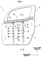
- FIG. 1 is a front view of a door outer panel in an embodiment of the present invention when viewed from an inner surface thereof;
- FIG. 2 is a cross-sectional view of a door body in the embodiment of the present invention, where the door body is cut from a portion corresponding to a line II-II of FIG 1;
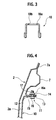
- FIG. 3 is an enlarged cross-sectional view of a reinforcement member along a line III-III of FIG. 1;
- FIG. 4 is an enlarged cross-sectional view of a portion IV in FIG. 2;
- FIG. 5 is an exploded perspective view of a joint portion of the reinforcement member and an outer-panel side member according to the embodiment of the present invention; and
- FIG. 6 is a perspective view showing a coupled state of the reinforcement member and the outer-panel side member according to the embodiment of the preset invention.
- Hereinafter, description will be made of embodiments of the present invention with reference to the drawings.
- FIG. 1 to FIG. 6 show an embodiment of a stiffening structure and stiffening method for an automotive outer panel according to the present invention. The stiffening structure and stiffening method for the automotive outer panel according to the present invention can be applied to a door. A description will be made below of this embodiment on the assumption that a door outer panel is the automotive outer panel.
- As shown in FIG. 1 and FIG. 2, a door 1 to which the stiffening structure of this embodiment is applied is formed of: a
door body 4 composed of a doorouter panel 2 and a door inner panel 3; and adoor window portion 5 having a window opening 5a opened/closed in such a manner that window glass (not shown) ascends/descends. On aninner surface 2a of the doorouter panel 2 as the automotive outer panel,stiffeners 10 as reinforcement members, which are channel-like in cross section, are provided. Thestiffeners 10 are adhered onto theinner surface 2a of the doorouter panel 2 while interposing amastic 6 as an adhesive therebetween. - As shown in FIG. 1, in this embodiment, the
stiffeners 10 are arranged in the up and down direction of a vehicle body. Moreover, twostiffeners 10 are provided substantially parallel to each other at a predetermined interval in the fore-and-aft direction of a vehicle, and are arranged substantially parallel to theinner surface 2a of the doorouter panel 2. - To an upper end of the door
outer panel 2, a belt-like door waist reinforcement 7 (outer-panel side member) is joined. Thedoor waist reinforcement 7 is provided along a lower side of the window opening 5a in the fore-and-aft direction of the vehicle. Thestiffeners 10 are attached onto the doorouter panel 2 while interposing thedoor waist reinforcement 7 therebetween. As shown in FIG. 2, in order to ensure rigidity, thedoor waist reinforcement 7 has a cross-sectional shape in which a center portion in the up and down direction of the vehicle body swells to the direction of the door inner panel 3.Flanges door waist reinforcement 7 in the up and down direction are fixed to theinner surface 2a of the doorouter panel 2. - As shown in FIG. 3, each of the
stiffeners 10 is formed into the channel shape in cross section, in which the door inner panel 3 side is opened. Moreover, in abottom wall 10a of eachstiffener 10, which is opposed to theinner surface 2a of the doorouter panel 2, a plurality of through-holes 10b are formed at an appropriate interval in the longitudinal direction of thestiffener 10. Moreover, with regard to each of thestiffeners 10, an upper end thereof is joined to thedoor waist reinforcement 7, and as shown in FIG. 2, a lower end thereof is spot-welded to astep portion 3a formed on a lower edge of the door inner panel 3. Furthermore, themastic 6 is brought into press contact with theinner surface 2a of the doorouter panel 2 in a state of being applied to spots among the through-holes 10b of thebottom wall 10a. - Here, in this embodiment, a
position adjuster 12 is provided in each ofjoint portions 11 of thestiffeners 10 and thedoor waist reinforcement 7. Specifically, with regard to eachstiffener 10 disposed substantially along the up and down direction, theposition adjuster 12 is provided on an upper end thereof. Each position adjuster 12 permits thestiffener 10 to make a positional change of approaching the doorouter panel 2 or moving away therefrom through themastic 6. Moreover, each position adjuster 12 makes it possible to completely fix thestiffener 10 to thedoor waist reinforcement 7 after the position of thestiffener 10 with respect to the doorouter panel 2 is firmly determined. - On the upper end of each
stiffener 10, a substantially horizontalfirst flange 13 is formed so as to close a terminal end of the channel-like cross section thereof as shown in FIG 4 and FIG. 5. Meanwhile, on the lower end of thedoor waist reinforcement 7, to which eachstiffener 10 is opposed, asecond flange 14 is formed substantially parallel to thefirst flange 13 to be bent in the direction to the door inner panel 3. When eachstiffener 10 is coupled to thedoor waist reinforcement 7, thesefirst flange 13 andsecond flange 14 are overlapped with each other. - Then, each of the
position adjusters 12 includes: anelongate hole 15; and abolt 16 and anut 16a as fastening members. Theelongate hole 15 is formed in thefirst flange 13 of thestiffener 10, and is extended in the direction where thestiffener 10 and the doorouter panel 2 are opposed to each other, that is, in the vehicle width direction. Thebolt 16 and thenut 16a couple thefirst flange 13 and thesecond flange 14 of thedoor waist reinforcement 7 to each other through theelongate hole 15. - In the
second flange 14, aninsertion hole 17 for thebolt 16 is formed in a spot thereof corresponding to theelongate hole 15. Onto an upper surface of thesecond flange 14, thenut 16a is welded coaxially with theinsertion hole 17, and thenut 16a is integrated as a weld nut with thesecond flange 14. - Then, when the
first flange 13 and thesecond flange 14 are coupled to each other, thebolt 16 is attached onto thenut 16a from below thefirst flange 13 as shown in FIG. 5. Specifically, therespective flanges elongate hole 15 and theinsertion hole 17 are matched with each other, and thereafter, thebolt 16 is inserted into theseelongate hole 15 andinsertion hole 17 and is screwed to thenut 16a as shown in FIG 4 and FIG. 6. - At this time, in a temporarily fastened state of the
bolt 16, where thebolt 16 is loosened, thefirst flange 13 is permitted to move relatively to thesecond flange 14 in a longitudinal direction (vehicle width direction) of theelongate hole 15. Meanwhile, thebolt 16 is tightened to be firmly fixed, whereby the relative movement between both of theflanges - Incidentally, paint baking treatment is performed in a state as shown in FIG. 2, where the door inner panel 3 is coupled to the door
outer panel 2 onto which thestiffeners 10 are attached. After this baking treatment, assembling of auxiliary parts (not shown) such as a window regulator and a door lock mechanism is performed from awork hole 3b formed in the door inner panel 3. Thework hole 3b is covered with a door trim in a final stage. - Hence, the
stiffeners 10 will be subjected to the baking treatment in a state of being adhered onto the doorouter panel 2 while interposing themastic 6 therebetween. Themastic 6 is heat-cured at a temperature at the time of the baking, and enhances adhesiveness thereof; however, has property to be heat-shrunk following such heat curing. - Hence, in the stiffening method for the door outer panel 2 (automotive outer panel) according to this embodiment, first, the paint baking treatment is performed in a state where the upper ends of the
stiffeners 10 are temporarily fixed to thedoor waist reinforcement 7 by theposition adjusters 12. After this baking treatment, such temporarily fixed portions of thestiffeners 10 and thedoor waist reinforcement 7 are firmly fixed. - As above, in accordance with the stiffening structure and stiffening method for the door
outer panel 2 according to this embodiment, theposition adjusters 12 which permit the positional changes of thestiffeners 10 in the vehicle width direction are provided on thejoint portions 11 of thedoor waist reinforcement 7 and the upper ends of thestiffeners 10 adhered onto the inner surface of the doorouter panel 2 while interposing themastic 6 therebetween. Accordingly, a gap between the doorouter panel 2 and eachstiffener 10 can be narrowed, thus making it possible to eliminate a bumpy appearance of the doorouter panel 2. Moreover, in this embodiment, in a period before the paint baking treatment, thebolts 16 of theposition adjusters 12 can be loosened, thus making it possible to set theposition adjusters 12 in a state where dimensional changes thereof are permitted, that is, in such a temporarily fixed state where thefirst flange 13 and thesecond flange 14 are moved relatively to each other. Accordingly, even if themastic 6 is heat-shrunk by the baking treatment, such heat shrinkage can be absorbed by the positional changes of theposition adjusters 12, thus making it possible to prevent distortion from occurring on the doorouter panel 2. - As described above, in this embodiment, the distortion of the door
outer panel 2 owing to the heat curing of themastic 6 can be prevented. Accordingly, the mastic that increases the rigidity thereof when being heat-cured becomes usable, and from this fact, coupling strength between thestiffeners 10 and the doorouter panel 2 can be increased more. Eventually, strength of the doorouter panel 2 can be increased more. - Then, in this embodiment, in a period after the baking treatment, while the heat shrinkage of the
mastic 6 is being stabilized, thebolts 16 of theposition adjusters 12 are tightened to be firmly fixed. Accordingly, the upper ends of thestiffeners 10 can be surely coupled to thedoor waist reinforcement 7, thus making it possible to ensure the strength of the doorouter panel 2. - Moreover, in this embodiment, the
stiffeners 10 are arranged substantially parallel to theinner surface 2a of the doorouter panel 2. Accordingly, the gap between the doorouter panel 2 and each of thesestiffeners 10 becomes substantially constant over the overall length of thestiffener 10, and a thickness of themastic 6 filled into the gap can be made substantially constant over the overall length of thestiffener 10. Hence, a heat shrinkage amount and adhesive force of themastic 6 can be made even over the overall length of eachstiffener 10, and a reinforcement effect for the doorouter panel 2 by thestiffeners 10 can be enhanced. - Moreover, each of the
position adjusters 12 is composed by providing: theelongate hole 15 formed in thefirst flange 13 of thestiffener 10 and extended in the direction where thestiffener 10 and the doorouter panel 2 are opposed to each other; and thebolt 16 and thenut 16a which couple thefirst flange 13 and thesecond flange 14 of thedoor waist reinforcement 7 to each other through theelongate hole 15. Accordingly, a configuration of eachposition adjuster 12 can be simplified. In addition, thebolt 16 is loosened, thus making it possible to set both of theflanges bolt 16 is tightened, thus making it possible to firmly fix both of theflanges - Furthermore, the
stiffeners 10 are arranged in the up and down direction of the doorouter panel 2, and theposition adjusters 12 are provided on the upper ends of thestiffeners 10. Accordingly, the distortion on the side where thewindow opening 5a is provided, that is, the distortion on the upper end of the doorouter panel 2, in which an insertion port for door glass is formed, can be eliminated, thus making it possible to smoothly guide the door glass to ascend and descend. - Incidentally, the description has been made of the present invention by taking the above-described embodiment as an example; however, without being limited to this embodiment, various types of other embodiments can be adopted within the scope without departing from the gist of the present invention. For example, such arranged positions of the
position adjusters 12 are not limited to the upper ends of thestiffeners 10 arranged in the up and down direction, and theposition adjusters 12 can be provided on the lower ends of thestiffeners 10, or on both of the upper and lower ends thereof. - Moreover, the present invention can also be applied to the case where the
stiffeners 10 are arranged in the fore-and-aft direction of the vehicle, or arranged to be inclined with respect to the up and down direction or the fore-and-aft direction. In this case, the position adjuster just needs to be provided on either of both end portions of eachstiffener 10. - Furthermore, the
elongate holes 15 of theposition adjusters 12 can also be formed in thesecond flanges 14 of thedoor waist reinforcement 7 without being formed in thefirst flanges 13 of thestiffeners 10. In this case, the nuts 16a are separated from thesecond flanges 14 so as to be freely movable relatively thereto. - As a matter of course, without being limited to the door
outer panel 2 shown in this embodiment, the present invention can also be applied to an outside plate of the vehicle body, for example, to a roof panel, a fender panel, and the like. - Moreover, the
mastic 6 is used as the adhesive in this embodiment; however, the adhesive may be such an adhesive other than themastic 6, which has heat resistance to heat at the time of the baking treatment. - The entire content of a
Japanese Patent Application No. P2006-240168 - Although the invention has been described above by reference to certain embodiments of the invention, the invention is not limited to the embodiments described above and modifications may become apparent to these skilled in the art, in light of the teachings herein. The scope of the invention is defined with reference to the following claims.
Claims (6)
- A stiffening structure for an automotive outer panel (2), the stiffening structure comprising:an outer-panel side member (7) fixed to the automotive outer panel (2);an annexed member (10) adhered onto an inner surface (2a) of the automotive outer panel (2) while interposing an adhesive (6) therebetween, at least one end of the annexed member (10) being joined to the outer-panel side member (7); anda position adjuster (12) provided on a joint portion (11) of the annexed member (10) and the outer-panel side member (7), the position adjuster (12) making the annexed member (10) movable in a direction of approaching the automotive outer panel (2) or moving away therefrom.
- The stiffening structure according to claim 1,
wherein the annexed member (10) is a reinforcement member disposed substantially parallel to the inner surface (2a) of the automotive outer panel (2). - The stiffening structure according to claim 1 or 2,
wherein the position adjuster (12) includes: an elongate hole (15) formed in the annexed member (10) or the outer-panel side member (7) and extended in a direction where the annexed member (10) and the automotive outer panel (2) are opposed to each other; and a fastening member (16, 16a) that couples the annexed member (10) and the outer-panel side member (7) through the elongate hole (15). - The stiffening structure according to any one of claims 1 to 3,
wherein the automotive outer panel (2) is a door outer panel, and the annexed member (10) is disposed substantially along an up and down direction of a vehicle body. - The stiffening structure according to any one of claims 1 to 4,
wherein the automotive outer panel (2) is a door outer panel, and the position adjuster (12) is provided on at least an upper end of the annexed member (10). - A stiffening method for an automotive outer panel (2) in which an annexed member (10) is adhered onto an inner surface (2a) thereof in a facing manner while interposing an adhesive (6) therebetween, the stiffening method comprising:temporarily fixing at least one end of the annexed member (10) to an outer-panel side member (7) fixed to the automotive outer panel (2) by a position adjuster (12) provided on a joint portion (11) of the annexed member (10) and the outer-panel side member (7), the position adjuster (12) making the annexed member (10) movable in a direction of approaching the automotive outer panel (2) or moving away therefrom;baking paint on the automotive outer panel (2) in the state where the annexed member (10) is temporarily fixed to the outer-panel side member (7); andafter baking the paint, completely fixing the temporarily fixed annexed member (10) and outer-panel side member (7).
Applications Claiming Priority (1)
| Application Number | Priority Date | Filing Date | Title |
|---|---|---|---|
| JP2006240168A JP2008062696A (en) | 2006-09-05 | 2006-09-05 | Car body outer plate stiffening structure and method |
Publications (1)
| Publication Number | Publication Date |
|---|---|
| EP1897715A2 true EP1897715A2 (en) | 2008-03-12 |
Family
ID=38982568
Family Applications (1)
| Application Number | Title | Priority Date | Filing Date |
|---|---|---|---|
| EP07016124A Withdrawn EP1897715A2 (en) | 2006-09-05 | 2007-08-16 | Stiffening structure and stiffening method for automotive outer panel |
Country Status (4)
| Country | Link |
|---|---|
| US (1) | US7475931B2 (en) |
| EP (1) | EP1897715A2 (en) |
| JP (1) | JP2008062696A (en) |
| CN (1) | CN101138989A (en) |
Families Citing this family (10)
| Publication number | Priority date | Publication date | Assignee | Title |
|---|---|---|---|---|
| US20070228769A1 (en) * | 2006-03-28 | 2007-10-04 | Dandekar Bhushan W | Side impact protection device packaged between inner and outer panels |
| JP2010083247A (en) * | 2008-09-30 | 2010-04-15 | Mazda Motor Corp | Method of manufacturing vehicle body |
| JP5548133B2 (en) * | 2008-10-14 | 2014-07-16 | リンテック株式会社 | Bonded body, roof structure, laminated sheet used therefor, and method of using laminated sheet |
| US20110011005A1 (en) * | 2009-07-14 | 2011-01-20 | Halliwell Martin C | Reinforced door frame construction for a vehicle |
| JP5772512B2 (en) * | 2011-10-28 | 2015-09-02 | トヨタ自動車株式会社 | Car side door structure |
| DE102012001025A1 (en) * | 2012-01-19 | 2013-07-25 | GM Global Technology Operations LLC (n. d. Ges. d. Staates Delaware) | Struts to the outer skin reinforcement for a sheet-metal outer skin of a motor vehicle |
| CN103625556A (en) * | 2013-12-06 | 2014-03-12 | 上汽通用五菱汽车股份有限公司 | Automobile front door outer plate windowsill reinforcing plate and automobile front door |
| JP6653602B2 (en) * | 2016-03-18 | 2020-02-26 | ベバスト ジャパン株式会社 | Panel structure and method of manufacturing the same |
| CN108216378B (en) * | 2016-12-21 | 2022-01-14 | 丰田自动车株式会社 | Vehicle panel structure |
| JP6693599B2 (en) | 2017-04-21 | 2020-05-13 | Jfeスチール株式会社 | Structure of joining part for panel parts and joining method |
Family Cites Families (2)
| Publication number | Priority date | Publication date | Assignee | Title |
|---|---|---|---|---|
| JPH0467514U (en) | 1990-10-18 | 1992-06-16 | ||
| US6679540B1 (en) * | 2003-03-07 | 2004-01-20 | Trim Trends Co., Llc | Epoxy bonded laminate door beam |
-
2006
- 2006-09-05 JP JP2006240168A patent/JP2008062696A/en active Pending
-
2007
- 2007-08-15 CN CNA2007101425403A patent/CN101138989A/en active Pending
- 2007-08-16 EP EP07016124A patent/EP1897715A2/en not_active Withdrawn
- 2007-08-28 US US11/892,871 patent/US7475931B2/en not_active Expired - Fee Related
Also Published As
| Publication number | Publication date |
|---|---|
| JP2008062696A (en) | 2008-03-21 |
| US20080054675A1 (en) | 2008-03-06 |
| CN101138989A (en) | 2008-03-12 |
| US7475931B2 (en) | 2009-01-13 |
Similar Documents
| Publication | Publication Date | Title |
|---|---|---|
| US7475931B2 (en) | Stiffening structure and stiffening method for automotive outer panel | |
| CN100506625C (en) | Improved motor vehicle front end to body side connection | |
| EP1733951B1 (en) | Connecting structure for hollow member or half hollow member | |
| US5094504A (en) | Upright pillar for a vehicle body structure | |
| US7390049B2 (en) | Vehicle door | |
| US20170240029A1 (en) | Door structure of automotive vehicle | |
| JP4733091B2 (en) | Automotive roof frame | |
| EP2468544B1 (en) | Upper part structure of vehicle | |
| US20040212222A1 (en) | Vehicle body structure | |
| US20130257101A1 (en) | Structure for side portion of vehicle body | |
| US20050062308A1 (en) | Separable connection between two adjoining vehicle body skin parts and method of making same | |
| US20090045650A1 (en) | Vehicle body side structure | |
| US4601511A (en) | Roof structure with reinforcement therefor for automotive vehicle | |
| CN114340984A (en) | Instrument panel support for a motor vehicle | |
| EP1785302B1 (en) | Door structure of a motor vehicle | |
| GB2184404A (en) | Motor vehicle with a roof mounted ventilation device | |
| CN110857123A (en) | Vehicle body structure for vehicle | |
| EP2454109A1 (en) | Reinforced door frame construction for a vehicle | |
| JP3925099B2 (en) | Panel connection structure | |
| US20200368802A1 (en) | Method for manufacturing vehicular side door, door component, and side door | |
| JP4021821B2 (en) | Door striker mounting structure | |
| EP1772351B1 (en) | Structural beam for a vehicle body. | |
| DE19824932A1 (en) | Connection between bodywork sheet component and reinforcement element | |
| DE102004019995B4 (en) | Sunroof module for vehicle, comprising guiding rail and cover made of single profile | |
| DE19821076A1 (en) | Vehicle bodywork with at least one door |
Legal Events
| Date | Code | Title | Description |
|---|---|---|---|
| PUAI | Public reference made under article 153(3) epc to a published international application that has entered the european phase |
Free format text: ORIGINAL CODE: 0009012 |
|
| 17P | Request for examination filed |
Effective date: 20070816 |
|
| AK | Designated contracting states |
Kind code of ref document: A2 Designated state(s): AT BE BG CH CY CZ DE DK EE ES FI FR GB GR HU IE IS IT LI LT LU LV MC MT NL PL PT RO SE SI SK TR |
|
| AX | Request for extension of the european patent |
Extension state: AL BA HR MK YU |
|
| STAA | Information on the status of an ep patent application or granted ep patent |
Free format text: STATUS: THE APPLICATION HAS BEEN WITHDRAWN |
|
| 18W | Application withdrawn |
Effective date: 20090423 |