EP1897368B1 - A method and apparatus for displaying data content - Google Patents
A method and apparatus for displaying data content Download PDFInfo
- Publication number
- EP1897368B1 EP1897368B1 EP06765769.2A EP06765769A EP1897368B1 EP 1897368 B1 EP1897368 B1 EP 1897368B1 EP 06765769 A EP06765769 A EP 06765769A EP 1897368 B1 EP1897368 B1 EP 1897368B1
- Authority
- EP
- European Patent Office
- Prior art keywords
- plane
- overlay
- video
- data content
- data
- Prior art date
- Legal status (The legal status is an assumption and is not a legal conclusion. Google has not performed a legal analysis and makes no representation as to the accuracy of the status listed.)
- Active
Links
Images


Classifications
-
- H—ELECTRICITY
- H04—ELECTRIC COMMUNICATION TECHNIQUE
- H04N—PICTORIAL COMMUNICATION, e.g. TELEVISION
- H04N21/00—Selective content distribution, e.g. interactive television or video on demand [VOD]
- H04N21/40—Client devices specifically adapted for the reception of or interaction with content, e.g. set-top-box [STB]; Operations thereof
- H04N21/47—End-user applications
- H04N21/488—Data services, e.g. news ticker
- H04N21/4884—Data services, e.g. news ticker for displaying subtitles
-
- H—ELECTRICITY
- H04—ELECTRIC COMMUNICATION TECHNIQUE
- H04N—PICTORIAL COMMUNICATION, e.g. TELEVISION
- H04N5/00—Details of television systems
- H04N5/44—Receiver circuitry for the reception of television signals according to analogue transmission standards
- H04N5/445—Receiver circuitry for the reception of television signals according to analogue transmission standards for displaying additional information
-
- H—ELECTRICITY
- H04—ELECTRIC COMMUNICATION TECHNIQUE
- H04N—PICTORIAL COMMUNICATION, e.g. TELEVISION
- H04N21/00—Selective content distribution, e.g. interactive television or video on demand [VOD]
- H04N21/40—Client devices specifically adapted for the reception of or interaction with content, e.g. set-top-box [STB]; Operations thereof
- H04N21/43—Processing of content or additional data, e.g. demultiplexing additional data from a digital video stream; Elementary client operations, e.g. monitoring of home network or synchronising decoder's clock; Client middleware
- H04N21/431—Generation of visual interfaces for content selection or interaction; Content or additional data rendering
- H04N21/4312—Generation of visual interfaces for content selection or interaction; Content or additional data rendering involving specific graphical features, e.g. screen layout, special fonts or colors, blinking icons, highlights or animations
-
- H—ELECTRICITY
- H04—ELECTRIC COMMUNICATION TECHNIQUE
- H04N—PICTORIAL COMMUNICATION, e.g. TELEVISION
- H04N21/00—Selective content distribution, e.g. interactive television or video on demand [VOD]
- H04N21/40—Client devices specifically adapted for the reception of or interaction with content, e.g. set-top-box [STB]; Operations thereof
- H04N21/47—End-user applications
-
- H—ELECTRICITY
- H04—ELECTRIC COMMUNICATION TECHNIQUE
- H04N—PICTORIAL COMMUNICATION, e.g. TELEVISION
- H04N7/00—Television systems
- H04N7/08—Systems for the simultaneous or sequential transmission of more than one television signal, e.g. additional information signals, the signals occupying wholly or partially the same frequency band, e.g. by time division
Definitions
- the invention relates to a method and apparatus for displaying a data content of an optical disk or TV broadcast.
- a video When displaying television programs, or data from optical disk, such as CD (Compact Disk), DVD (Digital Versatile Disk), BD (Blu-Ray Disk), or any other data media carriers, a video may have various elements overlaid over it (referred to as "overlay data" in the following).
- overlay data A typical example is subtitles usually placed at the bottom or top of video area.
- Other overlay may also include scoreboards, news tickers, or logos.
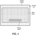
- Fig. 1 illustrates a conventional display where video data placed in a video plane and overlay data placed in an overlay plane are displayed.
- the overlay data e.g. subtitles
- the overlay data is located at the bottom of the video.
- part of video area is occulted by the overlay data.
- JP 09 046657 A discloses a closed caption decoder where an input video signal is given to a caption data extract section and a memory and an extracted caption is generated into character information by a decoder section.
- a video image given to the memory is given to a memory read control section, by which a size of the image is set at a display size setting section by means of a selection key and processed by a microcomputer so as not to be overlapped on the character information on a screen and the result is outputted as a video signal.
- the video signal and a prescribed video signal and the character information received for a selector are given to display control section, in which one image pattern by the video signal with a caption is generated.
- EP 0 766 470 A2 discloses a television receiver for teletext for receiving a composite video signal having text information multiplex on a television video signal, and more particularly to a television receiver for teletext capable of displaying the television video signal and teletext screen simultaneously on the picture screen by superimposing or dividing the screen, and according to this television receiver for teletext, which comprises preprocessing means for issuing various preprocessing correction signals on the basis of the teletext signal extracted by the teletext signal receiving means, the preprocessing correction signal issued by the preprocessing means, and the teletext signal received by the teletext signal receiving means are combined and displayed on the picture screen, and thereby the boundary of the television video signal and teletext signal is clearer, so that the text of thetelet ext signal is easier to read.
- EP 1 282 307 A2 discloses a data reproduction apparatus which is adapted to receive a first piece of caption information including a first piece of control information for displaying a caption on the screen of a television receiving set and a second piece of caption information including a second piece of control information for displaying the caption in a language different from that of the first piece of caption information, the apparatus comprising a controller for displaying the first and second pieces of caption information simultaneously without overlap by modifying the value of at least either of the first and second pieces of control information.
- US 2002/0080276 A1 discloses an image display system that can display images recorded by a plurality of image recording apparatuses in such a manner that the images are associated with each other.
- the image display system is comprised of a TV apparatus that captures and reproduces images recorded by the plurality of image recording apparatuses and additional information added thereto and then displays each of the reproduced images.
- the TV apparatus detects the presence or absence of relevancy between the images recorded by the plurality of image recording apparatuses based on the additional information captured and reproduced from the plurality of image recording apparatuses, and then displays, on a display, a related image display screen that allows a viewer to recognize the detected related images.
- EP 0 758 184 discloses a vertical scanning circuit of an apparatus which provides a sawtooth whose slope is electrically adjustable, and the apparatus provides the user with circuitry for controlling the position of the lower part of the picture by directly acting on the adjustment of the slope of the sawtooth, even though such an adjustment is generally realized in the factory or during maintenance.
- the vertical shift keys of the remote control unit are used to modify the slope of the sawtooth when a menu displayed on the screen is not being used.
- a method of adaptive the placement of overlay data in video is disclosed in US 2002/0196370 A1 .
- This document describes a method of placing overlay elements in images of a digital video so that desirable viewing areas of the images are not occluded by the overlay element.
- This method includes extracting frames from the video, each of the frames defining an image which may have one or more desirable viewing areas. For each frame an area is selected in the image for placing an overlay element and the percentage the overlay element overlaps the desirable viewing areas is determined for the selected area.
- the overlay element is placed in the selected area if the percentage is below a maximum allowed predetermined percentage of overlapping. If it is not, one or more other areas in the image are selected and/or the size, shape, aspect ratio of the overlay element is changed until a position and/or size, shape, aspect ratio is found which minimizes occlusion of the desirable viewing areas in the image.
- This known method has however some limitations. First, this method determines in real-time a percentage of the overlay data which overlap each desirable viewing area in each video frame so as to find the most suitable area to place the overlay data. This method is thus complex and requires a lot of expensive data processing means.
- the advantage of the proposed method and apparatus is that the overlay data and the video data can be shifted in a very easy way compared to each other, without any complex and expensive data processing means.
- the proposed method and apparatus allow that the overlay data no more occult the video plane. In other words, overlay data no more overlaps the video data, resulting in a better rendering for a user.
- Fig. 2 is a schematic block diagram illustrating an apparatus 200 to display data content according to the invention.
- the apparatus 200 may correspond to a TV, an optical disk player etc.
- the apparatus 200 comprises receiving means 210, splitting means 220, a decoder 230, shifting means 240, mixing means 250, outputting means 260, a display 270, interactive means 280, and adaptive means 290. All these elements of the apparatus 200 may be supported by at least one CPU with software or firmware.
- Receiving means 210 are used to receive input data content.
- the input data content comprises video data placed in a video plane and overlay data placed in an overlay plane.
- Receiving means 210 may correspond to be a buffer or a memory.
- the input data content can be coded or not be coded.
- the video data may be coded according to the MPEG-2 standard, and the overlay data (e.g. subtitles) may be coded according to text encoding algorithm.
- Splitting means 220 are used to split the input data content to video data placed in the video plane and overlay data placed in the overlay plane.
- the video data and the overlay data are thus separate streams.
- splitting means 220 corresponds to a de-multiplexer unit.
- splitting means 220 can be omitted in the apparatus 200.
- the decoder 230 is used to decode the input data content.
- the decoder 230 may comprise a first decoder 231 used to decode the video data, and a second decoder 232 used to decode the overlay data.
- the decoder 230 is an MPEG decoder.
- Shifting means 240 are used to shift the video plane compared to the video plane so as the overlay plane does not occult the video plane.
- Shifting means 240 may comprise a first shifter 241 used to shift the video plane compared to the overlay plane, and a second shifter 242 used to shift the overlay plane compared to the video plane.
- Shifting means 240 are intended to independently shift the video plane and/or the overlay plane along a vertical or horizontal direction.
- the shifting means 240 can thus shift the overlay plane to an area out of the video plane, or alternatively shift the video plane to an area out of the overlay plane.
- the overlay plane has been shifted along the vertical direction out of the video plane, and is located below the video plane in an unused area at the bottom of a display screen, so as the overlay plane does not occult the video plane.
- the overlay plane and the video plane have both been shifted along opposite vertical directions, so as the overlay plane is out of the video plane and located in an unused area at the top of the display screen without occulting the video plane.
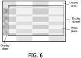
- the overlay plane has been shifted along the horizontal direction out of the video plane and is located in an unused area at the left of the display screen without occulting the video plane.
- Mixing means 250 are used to mix the resulting shifted video plane and overlay plane, for generating output data content, and to send the corresponding data stream to outputting means 260.
- Outputting means 260 are used to output the output data content from the mixing means 250.
- outputting means may correspond to a buffer or to an output driver.
- the output data content is intended to be displayed on a display 270, either being part of the apparatus 200 (e.g. LCD display if the apparatus is a computer or portable device), or separate from the apparatus 200 (e.g. TV display).
- a display 270 either being part of the apparatus 200 (e.g. LCD display if the apparatus is a computer or portable device), or separate from the apparatus 200 (e.g. TV display).
- Interactive means 280 are used to control the shifting means 240 to shift along horizontal or vertical direction the overlay plane and/or the video plane according to a user's indication.
- Interactive means 280 allow a user to interact with the apparatus 200, and to manually shift the overlay plane compared to the video plane.
- Interactive means 280 may be separate from the apparatus 200 (e.g. a remote control, a mouse, a keyboard), or alternatively part of the apparatus 200 (e.g. buttons placed on the front of the apparatus), from which the user presses numeral buttons, left/right buttons, up/down buttons, moves a mouse ball of a mouse to input shifting direction. In response, interactive means 280 send the corresponding shift value to shifting means 240.
- the apparatus 200 comprises adaptive means 290 used to automatically determine the shift of said video plane and/or said overlay plane.
- adaptive means 290 can calculate the shift value so as the overlay plane does not occult the video plane.
- Fig. 3 is a flow chart diagram of a method to display data content according to the invention.
- the method according to the invention comprises the steps of:
Description
- The invention relates to a method and apparatus for displaying a data content of an optical disk or TV broadcast.
- When displaying television programs, or data from optical disk, such as CD (Compact Disk), DVD (Digital Versatile Disk), BD (Blu-Ray Disk), or any other data media carriers, a video may have various elements overlaid over it (referred to as "overlay data" in the following). A typical example is subtitles usually placed at the bottom or top of video area. Other overlay may also include scoreboards, news tickers, or logos.
-
Fig. 1 illustrates a conventional display where video data placed in a video plane and overlay data placed in an overlay plane are displayed. Here, the overlay data (e.g. subtitles) is located at the bottom of the video. As a consequence, part of video area is occulted by the overlay data. - To solve this problem, some techniques are known for detecting semantic features and adaptively adjusting the placement of the overlay data in the display area.
-
JP 09 046657 A -
EP 0 766 470 A2 discloses a television receiver for teletext for receiving a composite video signal having text information multiplex on a television video signal, and more particularly to a television receiver for teletext capable of displaying the television video signal and teletext screen simultaneously on the picture screen by superimposing or dividing the screen, and according to this television receiver for teletext, which comprises preprocessing means for issuing various preprocessing correction signals on the basis of the teletext signal extracted by the teletext signal receiving means, the preprocessing correction signal issued by the preprocessing means, and the teletext signal received by the teletext signal receiving means are combined and displayed on the picture screen, and thereby the boundary of the television video signal and teletext signal is clearer, so that the text of thetelet ext signal is easier to read. -
EP 1 282 307 A2 discloses a data reproduction apparatus which is adapted to receive a first piece of caption information including a first piece of control information for displaying a caption on the screen of a television receiving set and a second piece of caption information including a second piece of control information for displaying the caption in a language different from that of the first piece of caption information, the apparatus comprising a controller for displaying the first and second pieces of caption information simultaneously without overlap by modifying the value of at least either of the first and second pieces of control information. -
US 2002/0080276 A1 discloses an image display system that can display images recorded by a plurality of image recording apparatuses in such a manner that the images are associated with each other. The image display system is comprised of a TV apparatus that captures and reproduces images recorded by the plurality of image recording apparatuses and additional information added thereto and then displays each of the reproduced images. The TV apparatus detects the presence or absence of relevancy between the images recorded by the plurality of image recording apparatuses based on the additional information captured and reproduced from the plurality of image recording apparatuses, and then displays, on a display, a related image display screen that allows a viewer to recognize the detected related images. -
EP 0 758 184 discloses a vertical scanning circuit of an apparatus which provides a sawtooth whose slope is electrically adjustable, and the apparatus provides the user with circuitry for controlling the position of the lower part of the picture by directly acting on the adjustment of the slope of the sawtooth, even though such an adjustment is generally realized in the factory or during maintenance. To this end, the vertical shift keys of the remote control unit are used to modify the slope of the sawtooth when a menu displayed on the screen is not being used. - A method of adaptive the placement of overlay data in video is disclosed in
US 2002/0196370 A1 . This document describes a method of placing overlay elements in images of a digital video so that desirable viewing areas of the images are not occluded by the overlay element. This method includes extracting frames from the video, each of the frames defining an image which may have one or more desirable viewing areas. For each frame an area is selected in the image for placing an overlay element and the percentage the overlay element overlaps the desirable viewing areas is determined for the selected area. The overlay element is placed in the selected area if the percentage is below a maximum allowed predetermined percentage of overlapping. If it is not, one or more other areas in the image are selected and/or the size, shape, aspect ratio of the overlay element is changed until a position and/or size, shape, aspect ratio is found which minimizes occlusion of the desirable viewing areas in the image. - This known method has however some limitations.
First, this method determines in real-time a percentage of the overlay data which overlap each desirable viewing area in each video frame so as to find the most suitable area to place the overlay data. This method is thus complex and requires a lot of expensive data processing means. - Secondly, even if overlay data are placed in the best desirable area of video, they still overlap the video, to the detriment of overall visual comfort for the viewer.
- It is an object of the invention to provide an improved method and apparatus for displaying data content comprising video data placed in a video plane and overlay data placed in an overlay plane, as defined in the appended claims.
- The advantage of the proposed method and apparatus is that the overlay data and the video data can be shifted in a very easy way compared to each other, without any complex and expensive data processing means.
- Also, the proposed method and apparatus allow that the overlay data no more occult the video plane. In other words, overlay data no more overlaps the video data, resulting in a better rendering for a user.
- These and other aspects of the method and apparatus of displaying data content, according to the invention will become apparent from and will be elucidated with respect to the implementations and embodiments described hereinafter and with reference to the accompanying drawings, wherein:
-
Fig. 1 illustrates by an example a conventional display of overlay data placed in an overlay plane and video data placed in a video plane; -
Fig. 2 is a schematic block diagram illustrating an apparatus to display data content according to the invention; -
Fig. 3 is a flow chart diagram of a method to display data content according to the invention; -
Fig. 4 illustrates by a first example the display of overlay data placed in an overlay plane and video data placed in a video plane according to the invention; -
Fig. 5 illustrates by a second example the display of overlay data placed in an overlay plane and video data placed in a video plane according to the invention; -
Fig. 6 illustrates by a third example the display of overlay data placed in an overlay plane and video data placed in a video plane according to the invention; - Same reference numerals are used to denote similar parts throughout the figures.
-
Fig. 2 is a schematic block diagram illustrating anapparatus 200 to display data content according to the invention. Theapparatus 200 may correspond to a TV, an optical disk player etc. - The
apparatus 200 comprisesreceiving means 210, splitting means 220, adecoder 230, shifting means 240, mixing means 250, outputting means 260, adisplay 270,interactive means 280, andadaptive means 290. All these elements of theapparatus 200 may be supported by at least one CPU with software or firmware. - Receiving means 210 are used to receive input data content. The input data content comprises video data placed in a video plane and overlay data placed in an overlay plane. Receiving means 210 may correspond to be a buffer or a memory. The input data content can be coded or not be coded. For example, the video data may be coded according to the MPEG-2 standard, and the overlay data (e.g. subtitles) may be coded according to text encoding algorithm.
- Splitting means 220 are used to split the input data content to video data placed in the video plane and overlay data placed in the overlay plane. The video data and the overlay data are thus separate streams. For example, if the input data content is a multiplexed stream (for example multiplexed into an MPEG or JPEG system stream), splitting means 220 corresponds to a de-multiplexer unit.
- If de-multiplexed video data and overlay data are directly available, then splitting
means 220 can be omitted in theapparatus 200. - If the input data content is coded, the
decoder 230 is used to decode the input data content. Thedecoder 230 may comprise afirst decoder 231 used to decode the video data, and asecond decoder 232 used to decode the overlay data. For example, if the input data content is coded according to an MPEG standard, thedecoder 230 is an MPEG decoder. - Shifting means 240 are used to shift the video plane compared to the video plane so as the overlay plane does not occult the video plane.
- Shifting means 240 may comprise a
first shifter 241 used to shift the video plane compared to the overlay plane, and asecond shifter 242 used to shift the overlay plane compared to the video plane. - Shifting means 240 are intended to independently shift the video plane and/or the overlay plane along a vertical or horizontal direction. The shifting means 240 can thus shift the overlay plane to an area out of the video plane, or alternatively shift the video plane to an area out of the overlay plane.
- For example, in
Fig. 4 , the overlay plane has been shifted along the vertical direction out of the video plane, and is located below the video plane in an unused area at the bottom of a display screen, so as the overlay plane does not occult the video plane. - For example, in
Fig. 5 , the overlay plane and the video plane have both been shifted along opposite vertical directions, so as the overlay plane is out of the video plane and located in an unused area at the top of the display screen without occulting the video plane. - For example, in
Fig. 6 , the overlay plane has been shifted along the horizontal direction out of the video plane and is located in an unused area at the left of the display screen without occulting the video plane. - Mixing means 250 are used to mix the resulting shifted video plane and overlay plane, for generating output data content, and to send the corresponding data stream to outputting means 260.
- Outputting means 260 are used to output the output data content from the mixing means 250. For example, outputting means may correspond to a buffer or to an output driver.
- The output data content is intended to be displayed on a
display 270, either being part of the apparatus 200 (e.g. LCD display if the apparatus is a computer or portable device), or separate from the apparatus 200 (e.g. TV display). - Interactive means 280 are used to control the shifting means 240 to shift along horizontal or vertical direction the overlay plane and/or the video plane according to a user's indication. Interactive means 280 allow a user to interact with the
apparatus 200, and to manually shift the overlay plane compared to the video plane. - Interactive means 280 may be separate from the apparatus 200 (e.g. a remote control, a mouse, a keyboard), or alternatively part of the apparatus 200 (e.g. buttons placed on the front of the apparatus), from which the user presses numeral buttons, left/right buttons, up/down buttons, moves a mouse ball of a mouse to input shifting direction. In response, interactive means 280 send the corresponding shift value to shifting
means 240. - Advantageously, the
apparatus 200 comprisesadaptive means 290 used to automatically determine the shift of said video plane and/or said overlay plane. To this end, by calculating the position of the video plane and the overlay plane in the display screen,adaptive means 290 can calculate the shift value so as the overlay plane does not occult the video plane. -
Fig. 3 is a flow chart diagram of a method to display data content according to the invention. The method according to the invention comprises the steps of: - receiving (301) data content comprising video data placed in a video plane and overlay data placed in an overlay plane. The data content may come from an optical disk, TV broadcast etc.
- splitting (302) the video data and the overlay data. The video data and the overlay data are separate streams that are multiplexed into an MPEG or JPEG system stream. The video data and the overlay data may be split by a method of de-multiplexing. If de-multiplexed video data and overlay data are directly available, the step of splitting (302) can be omitted (cf. corresponding dashed lines).
- decoding (303) the video data and the overlay data. If the video data and the overlay data are not coded, the decoding step can be ignored (cf. corresponding dashed lines).
- determining (304) a shift value. The shift value is either manually done by a user (via a remote control, mouse, keyboard etc.), or alternatively automatically in calculating the position of the video plane and the overlay plane in a display screen, then calculating the shift value so as the overlay plane does not occult the video plane.
- shifting (305) the overlay plane compared to the overlay plane so as the overlay plane does not occult the video plane. The shifting step is intended to independently shift the video plane and/or the overlay plane along a vertical or horizontal direction. The shifting step can thus shift the overlay plane to an area out of the video plane, or alternatively shift the video plane to an area out of the overlay plane, as shown in
Figs. 4, 5 , or6 . - mixing (306) the video plane and the overlay plane which have been shifted for generating output data content.
- outputting (307) the output data content. The outputting stream of the data content can be outputted to a display screen, such as TV display, computer display etc.
- displaying (308) the output data content on the display screen.
- It should be noted that the above-mentioned embodiments illustrate rather than limit the invention and that those skilled in the art will be able to design alternative embodiments without departing from the scope of the appended claims. In the claims, any reference signs placed between parentheses shall not be constructed as limiting the claim. The word 'comprising' does not exclude the presence of elements or steps not listed in a claim. The word "a" or "an" preceding an element does not exclude the presence of a plurality of such elements. The invention can be implemented by means of hardware comprising several distinct elements and by means of a suitable programmed computer. In the means claims enumerating several means, several of these means can be embodied by one and the same item of hardware. The usage of the words first, second and third, etcetera do not indicate any ordering. These words are to be interpreted as names.
Claims (4)
- A method of displaying video data placed in a video plane and overlay data placed in an overlay plane in the form of output data content having a spatial size fitting both the video plane and the overlay plane side by side, said method comprising the steps of:- receiving coded input data content comprising an encoded version of the video data and the overlay data,- decoding the coded input data content to obtain the video data providing the video plane and the overlay data providing the overlay plane;- adaptively positioning the overlay plane in an area in which the overlay plane does not occult the video plane by only shifting (305) the video plane compared to the overlay plane, said shifting comprising automatically determining (304) a shift value to indicate the shift to be applied to said video plane and/or said overlay plane,- mixing (306) the resulting video plane and overlay plane, for generating output data content,- after the mixing, outputting (307) the output data content to a display screen,- using the display screen, displaying (308) the output data content,the method further comprising:- enabling a user to interactively control the shift of said video plane and/or said overlay plane along a vertical or horizontal direction.
- An apparatus for displaying video data placed in a video plane and overlay data placed in an overlay plane in the form of output data content having a spatial size fitting both the video plane and the overlay plane side by side, said apparatus comprising:- receiving means (210) for receiving coded input data content comprising an encoded version of the video data and the overlay data,- a decoder (230) for decoding the coded input data content to obtain the video data providing the video plane and the overlay data providing the overlay plane,- shifting means (240) for shifting the video plane compared to the overlay plane,- adaptive means (290) for positioning the overlay plane in an area in which the overlay plane does not occult the video plane by only determining a shift value of said video plane and/or said overlay plane for the shifting means;- mixing means (250) for mixing the resulting video plane and overlay plane, for generating output data content,- outputting means (260) for outputing the output data content from the mixing means (250) to a display (270),- the display (270), configured for displaying the output data content, and- interactive means (280) for enabling a user to interactively control the shift of said video plane and/or said overlay plane along a vertical or horizontal direction.
- An apparatus as claimed in claim 2, wherein said interactive means (280) is a remote control, a mouse, or a keyboard.
- An apparatus as claimed in claim 2, wherein said shifting means (240) comprises a first shifter (241) for shifting the video plane to an area out of the overlay plane, and a second shifter (242) for shifting the overlay plane to an area out of the video plane.
Applications Claiming Priority (2)
| Application Number | Priority Date | Filing Date | Title |
|---|---|---|---|
| CN200510082369 | 2005-06-22 | ||
| PCT/IB2006/051938 WO2006136989A1 (en) | 2005-06-22 | 2006-06-16 | A method and apparatus for displaying data content |
Publications (2)
| Publication Number | Publication Date |
|---|---|
| EP1897368A1 EP1897368A1 (en) | 2008-03-12 |
| EP1897368B1 true EP1897368B1 (en) | 2018-02-21 |
Family
ID=37110728
Family Applications (1)
| Application Number | Title | Priority Date | Filing Date |
|---|---|---|---|
| EP06765769.2A Active EP1897368B1 (en) | 2005-06-22 | 2006-06-16 | A method and apparatus for displaying data content |
Country Status (9)
| Country | Link |
|---|---|
| US (1) | US8854546B2 (en) |
| EP (1) | EP1897368B1 (en) |
| JP (1) | JP5475281B2 (en) |
| KR (1) | KR20080019719A (en) |
| CN (1) | CN100588232C (en) |
| MY (1) | MY162855A (en) |
| TR (1) | TR201806795T4 (en) |
| TW (1) | TWI410956B (en) |
| WO (1) | WO2006136989A1 (en) |
Families Citing this family (12)
| Publication number | Priority date | Publication date | Assignee | Title |
|---|---|---|---|---|
| EP1897368B1 (en) | 2005-06-22 | 2018-02-21 | Koninklijke Philips N.V. | A method and apparatus for displaying data content |
| JP5093557B2 (en) * | 2006-10-10 | 2012-12-12 | ソニー株式会社 | Image processing apparatus, image processing method, and program |
| WO2009083885A1 (en) | 2007-12-26 | 2009-07-09 | Koninklijke Philips Electronics N.V. | Image processor for overlaying a graphics object |
| EP2399398B1 (en) * | 2009-02-17 | 2016-04-20 | Koninklijke Philips N.V. | Combining 3d image and graphical data |
| EP2262230A1 (en) | 2009-06-08 | 2010-12-15 | Koninklijke Philips Electronics N.V. | Device and method for processing video data |
| US8878996B2 (en) * | 2009-12-11 | 2014-11-04 | Motorola Mobility Llc | Selective decoding of an input stream |
| US9025933B2 (en) * | 2010-02-12 | 2015-05-05 | Sony Corporation | Information processing device, information processing method, playback device, playback method, program and recording medium |
| CN103004225B (en) | 2010-07-15 | 2015-09-16 | 联发科技(新加坡)私人有限公司 | For multiple vision signal to be shown in video process apparatus on display device and method simultaneously |
| US8629939B1 (en) * | 2012-11-05 | 2014-01-14 | Lsi Corporation | Television ticker overlay |
| US9716737B2 (en) * | 2013-05-08 | 2017-07-25 | Qualcomm Incorporated | Video streaming in a wireless communication system |
| US11134301B2 (en) | 2018-11-15 | 2021-09-28 | Jujo, Inc., a Delaware corporation | Method and system of data polling for augmented/mixed reality applications |
| JP7207158B2 (en) * | 2019-05-21 | 2023-01-18 | 株式会社デンソー | display controller |
Family Cites Families (28)
| Publication number | Priority date | Publication date | Assignee | Title |
|---|---|---|---|---|
| JPH0627407Y2 (en) * | 1989-06-30 | 1994-07-27 | トキワケミカル工業株式会社 | Molding glitter tape |
| JP2664611B2 (en) * | 1992-11-18 | 1997-10-15 | 三洋電機株式会社 | Closed caption decoder and television receiver having the same |
| GB9312690D0 (en) * | 1993-06-18 | 1993-08-04 | Philips Electronics Uk Ltd | Television receiver |
| JPH0946657A (en) | 1995-08-02 | 1997-02-14 | Sharp Corp | Closed caption decoder |
| JP3771954B2 (en) * | 1995-08-04 | 2006-05-10 | ソニー株式会社 | Image display control apparatus and method |
| KR100426109B1 (en) | 1995-08-09 | 2004-08-16 | 코닌클리케 필립스 일렉트로닉스 엔.브이. | Picture display apparatus in which the lower part of the picture is shifted |
| US5801753A (en) * | 1995-08-11 | 1998-09-01 | General Instrument Corporation Of Delaware | Method and apparatus for providing an interactive guide to events available on an information network |
| JPH0993548A (en) * | 1995-09-27 | 1997-04-04 | Toshiba Corp | Television receiver with teletext information display function |
| JPH0998389A (en) | 1995-09-29 | 1997-04-08 | Matsushita Electric Ind Co Ltd | Television receiver for teletext broadcasting |
| KR100424755B1 (en) | 1995-09-29 | 2004-08-30 | 마쯔시다덴기산교 가부시키가이샤 | Television receiver |
| JPH09214847A (en) * | 1996-01-30 | 1997-08-15 | Sharp Corp | Video signal processor |
| JP2000253392A (en) * | 1999-03-01 | 2000-09-14 | Hitachi Denshi Ltd | Method for displaying picture and information in supervisory recorder |
| JP2002016885A (en) | 2000-06-30 | 2002-01-18 | Pioneer Electronic Corp | Apparatus and method for reproducing picture |
| US7228061B2 (en) * | 2000-11-17 | 2007-06-05 | Canon Kabushiki Kaisha | Image display system, image reproducing apparatus, digital television apparatus, image display method, and storage medium for controlling image display based on additional information read from multiple image recording apparatuses |
| JP2002199354A (en) * | 2000-12-25 | 2002-07-12 | Toshiba Corp | Digital broadcasting receiver and its control method |
| JP2002232802A (en) * | 2001-01-31 | 2002-08-16 | Mitsubishi Electric Corp | Video display device |
| US6778224B2 (en) | 2001-06-25 | 2004-08-17 | Koninklijke Philips Electronics N.V. | Adaptive overlay element placement in video |
| JP2003037792A (en) | 2001-07-25 | 2003-02-07 | Toshiba Corp | Data reproducing device and data reproducing method |
| US7224404B2 (en) * | 2001-07-30 | 2007-05-29 | Samsung Electronics Co., Ltd. | Remote display control of video/graphics data |
| US20030189669A1 (en) * | 2002-04-05 | 2003-10-09 | Bowser Todd S. | Method for off-image data display |
| JP2003333453A (en) | 2002-05-15 | 2003-11-21 | Mitsubishi Electric Corp | Television receiver and screen position control method |
| AU2003297080A1 (en) * | 2002-12-16 | 2004-07-29 | Microsoft Corporation | Systems and methods for interfacing with computer devices |
| JP2004208014A (en) * | 2002-12-25 | 2004-07-22 | Mitsubishi Electric Corp | Subtitle display device and subtitle display program |
| JP2004221751A (en) * | 2003-01-10 | 2004-08-05 | Funai Electric Co Ltd | Image signal processing device |
| US7106381B2 (en) * | 2003-03-24 | 2006-09-12 | Sony Corporation | Position and time sensitive closed captioning |
| KR20040099058A (en) * | 2003-05-17 | 2004-11-26 | 삼성전자주식회사 | Method for processing subtitle stream, reproducing apparatus and information storage medium thereof |
| KR20050072255A (en) * | 2004-01-06 | 2005-07-11 | 엘지전자 주식회사 | Method for managing and reproducing a subtitle of high density optical disc |
| EP1897368B1 (en) | 2005-06-22 | 2018-02-21 | Koninklijke Philips N.V. | A method and apparatus for displaying data content |
-
2006
- 2006-06-16 EP EP06765769.2A patent/EP1897368B1/en active Active
- 2006-06-16 JP JP2008517653A patent/JP5475281B2/en active Active
- 2006-06-16 US US11/917,943 patent/US8854546B2/en active Active
- 2006-06-16 KR KR1020087001711A patent/KR20080019719A/en active Search and Examination
- 2006-06-16 TR TR2018/06795T patent/TR201806795T4/en unknown
- 2006-06-16 WO PCT/IB2006/051938 patent/WO2006136989A1/en active Application Filing
- 2006-06-16 CN CN200680022504A patent/CN100588232C/en active Active
- 2006-06-20 MY MYPI20062919A patent/MY162855A/en unknown
- 2006-06-21 TW TW095122294A patent/TWI410956B/en active
Also Published As
| Publication number | Publication date |
|---|---|
| US8854546B2 (en) | 2014-10-07 |
| WO2006136989A1 (en) | 2006-12-28 |
| CN101204087A (en) | 2008-06-18 |
| EP1897368A1 (en) | 2008-03-12 |
| JP5475281B2 (en) | 2014-04-16 |
| US20100214485A1 (en) | 2010-08-26 |
| CN100588232C (en) | 2010-02-03 |
| JP2008544677A (en) | 2008-12-04 |
| TW200802300A (en) | 2008-01-01 |
| MY162855A (en) | 2017-07-31 |
| KR20080019719A (en) | 2008-03-04 |
| TR201806795T4 (en) | 2018-06-21 |
| TWI410956B (en) | 2013-10-01 |
Similar Documents
| Publication | Publication Date | Title |
|---|---|---|
| EP1897368B1 (en) | A method and apparatus for displaying data content | |
| EP2525568B1 (en) | Automatic subtitle resizing | |
| EP2559230B1 (en) | Method for displaying a video stream according to a customised format | |
| KR100617178B1 (en) | Apparatus and method for zoom transfer of television system | |
| EP1547372B1 (en) | Apparatus for receiving a digital information signal | |
| US7692722B2 (en) | Caption service menu display apparatus and method | |
| US7944506B2 (en) | Caption presentation method and apparatus using same | |
| JP2008167265A (en) | Display structure, television set and screen display method for television set | |
| KR100253211B1 (en) | Screen display control apparatus and method for display | |
| EP1848203B1 (en) | Method and system for video image aspect ratio conversion | |
| JP2004221751A (en) | Image signal processing device | |
| KR100618227B1 (en) | Method and apparatus for processing a caption of an image display device | |
| JP2007243292A (en) | Video display apparatus, video display method, and program | |
| KR100474322B1 (en) | Sub image display control device and method | |
| KR101074592B1 (en) | Method and apparatus for processing (a) caption of (an) image display device | |
| KR20100072681A (en) | Apparatus and method for image displaying in image display device | |
| US20050151757A1 (en) | Image display apparatus | |
| KR20070081657A (en) | Caption expression method in digital video output apparutus | |
| JP2006319582A (en) | Display control method and display controller |
Legal Events
| Date | Code | Title | Description |
|---|---|---|---|
| PUAI | Public reference made under article 153(3) epc to a published international application that has entered the european phase |
Free format text: ORIGINAL CODE: 0009012 |
|
| 17P | Request for examination filed |
Effective date: 20080122 |
|
| AK | Designated contracting states |
Kind code of ref document: A1 Designated state(s): AT BE BG CH CY CZ DE DK EE ES FI FR GB GR HU IE IS IT LI LT LU LV MC NL PL PT RO SE SI SK TR |
|
| DAX | Request for extension of the european patent (deleted) | ||
| DAX | Request for extension of the european patent (deleted) | ||
| 17Q | First examination report despatched |
Effective date: 20090114 |
|
| RAP1 | Party data changed (applicant data changed or rights of an application transferred) |
Owner name: KONINKLIJKE PHILIPS N.V. |
|
| GRAP | Despatch of communication of intention to grant a patent |
Free format text: ORIGINAL CODE: EPIDOSNIGR1 |
|
| INTG | Intention to grant announced |
Effective date: 20170907 |
|
| RIN1 | Information on inventor provided before grant (corrected) |
Inventor name: TKACHENKO, SERHIY |
|
| GRAS | Grant fee paid |
Free format text: ORIGINAL CODE: EPIDOSNIGR3 |
|
| GRAA | (expected) grant |
Free format text: ORIGINAL CODE: 0009210 |
|
| AK | Designated contracting states |
Kind code of ref document: B1 Designated state(s): AT BE BG CH CY CZ DE DK EE ES FI FR GB GR HU IE IS IT LI LT LU LV MC NL PL PT RO SE SI SK TR |
|
| REG | Reference to a national code |
Ref country code: GB Ref legal event code: FG4D |
|
| REG | Reference to a national code |
Ref country code: CH Ref legal event code: EP |
|
| REG | Reference to a national code |
Ref country code: DE Ref legal event code: R096 Ref document number: 602006054746 Country of ref document: DE Ref country code: AT Ref legal event code: REF Ref document number: 972931 Country of ref document: AT Kind code of ref document: T Effective date: 20180315 |
|
| REG | Reference to a national code |
Ref country code: IE Ref legal event code: FG4D |
|
| REG | Reference to a national code |
Ref country code: NL Ref legal event code: MP Effective date: 20180221 |
|
| REG | Reference to a national code |
Ref country code: FR Ref legal event code: PLFP Year of fee payment: 13 |
|
| REG | Reference to a national code |
Ref country code: LT Ref legal event code: MG4D |
|
| REG | Reference to a national code |
Ref country code: AT Ref legal event code: MK05 Ref document number: 972931 Country of ref document: AT Kind code of ref document: T Effective date: 20180221 |
|
| PG25 | Lapsed in a contracting state [announced via postgrant information from national office to epo] |
Ref country code: FI Free format text: LAPSE BECAUSE OF FAILURE TO SUBMIT A TRANSLATION OF THE DESCRIPTION OR TO PAY THE FEE WITHIN THE PRESCRIBED TIME-LIMIT Effective date: 20180221 Ref country code: CY Free format text: LAPSE BECAUSE OF FAILURE TO SUBMIT A TRANSLATION OF THE DESCRIPTION OR TO PAY THE FEE WITHIN THE PRESCRIBED TIME-LIMIT Effective date: 20180221 Ref country code: ES Free format text: LAPSE BECAUSE OF FAILURE TO SUBMIT A TRANSLATION OF THE DESCRIPTION OR TO PAY THE FEE WITHIN THE PRESCRIBED TIME-LIMIT Effective date: 20180221 Ref country code: NL Free format text: LAPSE BECAUSE OF FAILURE TO SUBMIT A TRANSLATION OF THE DESCRIPTION OR TO PAY THE FEE WITHIN THE PRESCRIBED TIME-LIMIT Effective date: 20180221 Ref country code: LT Free format text: LAPSE BECAUSE OF FAILURE TO SUBMIT A TRANSLATION OF THE DESCRIPTION OR TO PAY THE FEE WITHIN THE PRESCRIBED TIME-LIMIT Effective date: 20180221 |
|
| PG25 | Lapsed in a contracting state [announced via postgrant information from national office to epo] |
Ref country code: GR Free format text: LAPSE BECAUSE OF FAILURE TO SUBMIT A TRANSLATION OF THE DESCRIPTION OR TO PAY THE FEE WITHIN THE PRESCRIBED TIME-LIMIT Effective date: 20180522 Ref country code: BG Free format text: LAPSE BECAUSE OF FAILURE TO SUBMIT A TRANSLATION OF THE DESCRIPTION OR TO PAY THE FEE WITHIN THE PRESCRIBED TIME-LIMIT Effective date: 20180521 Ref country code: AT Free format text: LAPSE BECAUSE OF FAILURE TO SUBMIT A TRANSLATION OF THE DESCRIPTION OR TO PAY THE FEE WITHIN THE PRESCRIBED TIME-LIMIT Effective date: 20180221 Ref country code: SE Free format text: LAPSE BECAUSE OF FAILURE TO SUBMIT A TRANSLATION OF THE DESCRIPTION OR TO PAY THE FEE WITHIN THE PRESCRIBED TIME-LIMIT Effective date: 20180221 Ref country code: LV Free format text: LAPSE BECAUSE OF FAILURE TO SUBMIT A TRANSLATION OF THE DESCRIPTION OR TO PAY THE FEE WITHIN THE PRESCRIBED TIME-LIMIT Effective date: 20180221 |
|
| PG25 | Lapsed in a contracting state [announced via postgrant information from national office to epo] |
Ref country code: PL Free format text: LAPSE BECAUSE OF FAILURE TO SUBMIT A TRANSLATION OF THE DESCRIPTION OR TO PAY THE FEE WITHIN THE PRESCRIBED TIME-LIMIT Effective date: 20180221 Ref country code: EE Free format text: LAPSE BECAUSE OF FAILURE TO SUBMIT A TRANSLATION OF THE DESCRIPTION OR TO PAY THE FEE WITHIN THE PRESCRIBED TIME-LIMIT Effective date: 20180221 Ref country code: RO Free format text: LAPSE BECAUSE OF FAILURE TO SUBMIT A TRANSLATION OF THE DESCRIPTION OR TO PAY THE FEE WITHIN THE PRESCRIBED TIME-LIMIT Effective date: 20180221 Ref country code: IT Free format text: LAPSE BECAUSE OF FAILURE TO SUBMIT A TRANSLATION OF THE DESCRIPTION OR TO PAY THE FEE WITHIN THE PRESCRIBED TIME-LIMIT Effective date: 20180221 |
|
| REG | Reference to a national code |
Ref country code: DE Ref legal event code: R097 Ref document number: 602006054746 Country of ref document: DE |
|
| PG25 | Lapsed in a contracting state [announced via postgrant information from national office to epo] |
Ref country code: SK Free format text: LAPSE BECAUSE OF FAILURE TO SUBMIT A TRANSLATION OF THE DESCRIPTION OR TO PAY THE FEE WITHIN THE PRESCRIBED TIME-LIMIT Effective date: 20180221 Ref country code: DK Free format text: LAPSE BECAUSE OF FAILURE TO SUBMIT A TRANSLATION OF THE DESCRIPTION OR TO PAY THE FEE WITHIN THE PRESCRIBED TIME-LIMIT Effective date: 20180221 Ref country code: CZ Free format text: LAPSE BECAUSE OF FAILURE TO SUBMIT A TRANSLATION OF THE DESCRIPTION OR TO PAY THE FEE WITHIN THE PRESCRIBED TIME-LIMIT Effective date: 20180221 |
|
| PLBE | No opposition filed within time limit |
Free format text: ORIGINAL CODE: 0009261 |
|
| STAA | Information on the status of an ep patent application or granted ep patent |
Free format text: STATUS: NO OPPOSITION FILED WITHIN TIME LIMIT |
|
| 26N | No opposition filed |
Effective date: 20181122 |
|
| REG | Reference to a national code |
Ref country code: CH Ref legal event code: PL |
|
| PG25 | Lapsed in a contracting state [announced via postgrant information from national office to epo] |
Ref country code: SI Free format text: LAPSE BECAUSE OF FAILURE TO SUBMIT A TRANSLATION OF THE DESCRIPTION OR TO PAY THE FEE WITHIN THE PRESCRIBED TIME-LIMIT Effective date: 20180221 |
|
| REG | Reference to a national code |
Ref country code: BE Ref legal event code: MM Effective date: 20180630 |
|
| REG | Reference to a national code |
Ref country code: IE Ref legal event code: MM4A |
|
| PG25 | Lapsed in a contracting state [announced via postgrant information from national office to epo] |
Ref country code: LU Free format text: LAPSE BECAUSE OF NON-PAYMENT OF DUE FEES Effective date: 20180616 Ref country code: MC Free format text: LAPSE BECAUSE OF FAILURE TO SUBMIT A TRANSLATION OF THE DESCRIPTION OR TO PAY THE FEE WITHIN THE PRESCRIBED TIME-LIMIT Effective date: 20180221 |
|
| PG25 | Lapsed in a contracting state [announced via postgrant information from national office to epo] |
Ref country code: IE Free format text: LAPSE BECAUSE OF NON-PAYMENT OF DUE FEES Effective date: 20180616 Ref country code: CH Free format text: LAPSE BECAUSE OF NON-PAYMENT OF DUE FEES Effective date: 20180630 Ref country code: LI Free format text: LAPSE BECAUSE OF NON-PAYMENT OF DUE FEES Effective date: 20180630 |
|
| PG25 | Lapsed in a contracting state [announced via postgrant information from national office to epo] |
Ref country code: BE Free format text: LAPSE BECAUSE OF NON-PAYMENT OF DUE FEES Effective date: 20180630 |
|
| PG25 | Lapsed in a contracting state [announced via postgrant information from national office to epo] |
Ref country code: HU Free format text: LAPSE BECAUSE OF FAILURE TO SUBMIT A TRANSLATION OF THE DESCRIPTION OR TO PAY THE FEE WITHIN THE PRESCRIBED TIME-LIMIT; INVALID AB INITIO Effective date: 20060616 Ref country code: PT Free format text: LAPSE BECAUSE OF FAILURE TO SUBMIT A TRANSLATION OF THE DESCRIPTION OR TO PAY THE FEE WITHIN THE PRESCRIBED TIME-LIMIT Effective date: 20180221 |
|
| PG25 | Lapsed in a contracting state [announced via postgrant information from national office to epo] |
Ref country code: IS Free format text: LAPSE BECAUSE OF FAILURE TO SUBMIT A TRANSLATION OF THE DESCRIPTION OR TO PAY THE FEE WITHIN THE PRESCRIBED TIME-LIMIT Effective date: 20180621 |
|
| PGFP | Annual fee paid to national office [announced via postgrant information from national office to epo] |
Ref country code: FR Payment date: 20230622 Year of fee payment: 18 Ref country code: DE Payment date: 20230627 Year of fee payment: 18 |
|
| PGFP | Annual fee paid to national office [announced via postgrant information from national office to epo] |
Ref country code: TR Payment date: 20230602 Year of fee payment: 18 |
|
| PGFP | Annual fee paid to national office [announced via postgrant information from national office to epo] |
Ref country code: GB Payment date: 20230620 Year of fee payment: 18 |