EP1896791B1 - Wärmespeicher hoher speicherdichte - Google Patents
Wärmespeicher hoher speicherdichte Download PDFInfo
- Publication number
- EP1896791B1 EP1896791B1 EP06763673A EP06763673A EP1896791B1 EP 1896791 B1 EP1896791 B1 EP 1896791B1 EP 06763673 A EP06763673 A EP 06763673A EP 06763673 A EP06763673 A EP 06763673A EP 1896791 B1 EP1896791 B1 EP 1896791B1
- Authority
- EP
- European Patent Office
- Prior art keywords
- heat
- working medium
- heat carrier
- flow
- tubes
- Prior art date
- Legal status (The legal status is an assumption and is not a legal conclusion. Google has not performed a legal analysis and makes no representation as to the accuracy of the status listed.)
- Not-in-force
Links
- 238000003860 storage Methods 0.000 title claims abstract description 19
- 239000002594 sorbent Substances 0.000 claims abstract description 62
- 239000000463 material Substances 0.000 claims abstract description 30
- 238000000034 method Methods 0.000 claims abstract description 22
- 238000001179 sorption measurement Methods 0.000 claims abstract description 15
- 239000000835 fiber Substances 0.000 claims abstract description 6
- XLYOFNOQVPJJNP-UHFFFAOYSA-N water Substances O XLYOFNOQVPJJNP-UHFFFAOYSA-N 0.000 claims description 8
- 229910052751 metal Inorganic materials 0.000 claims description 7
- 239000002184 metal Substances 0.000 claims description 7
- 239000004745 nonwoven fabric Substances 0.000 claims description 7
- 238000009833 condensation Methods 0.000 claims description 5
- 230000005494 condensation Effects 0.000 claims description 5
- 238000003795 desorption Methods 0.000 claims description 5
- 239000010457 zeolite Substances 0.000 claims description 5
- 229910021536 Zeolite Inorganic materials 0.000 claims description 4
- 239000011324 bead Substances 0.000 claims description 4
- HNPSIPDUKPIQMN-UHFFFAOYSA-N dioxosilane;oxo(oxoalumanyloxy)alumane Chemical compound O=[Si]=O.O=[Al]O[Al]=O HNPSIPDUKPIQMN-UHFFFAOYSA-N 0.000 claims description 4
- 238000009834 vaporization Methods 0.000 claims description 4
- 239000002131 composite material Substances 0.000 claims description 3
- 239000008187 granular material Substances 0.000 claims description 3
- 238000007654 immersion Methods 0.000 claims description 3
- 238000003825 pressing Methods 0.000 claims description 3
- 239000012858 resilient material Substances 0.000 claims description 3
- VYPSYNLAJGMNEJ-UHFFFAOYSA-N Silicium dioxide Chemical compound O=[Si]=O VYPSYNLAJGMNEJ-UHFFFAOYSA-N 0.000 claims description 2
- 239000003463 adsorbent Substances 0.000 claims description 2
- -1 salt hydrates Chemical class 0.000 claims description 2
- 238000012546 transfer Methods 0.000 abstract description 81
- 239000002918 waste heat Substances 0.000 abstract description 4
- 238000005516 engineering process Methods 0.000 abstract description 3
- 230000001976 improved effect Effects 0.000 abstract description 2
- 230000000737 periodic effect Effects 0.000 abstract description 2
- 239000012530 fluid Substances 0.000 description 59
- 238000005338 heat storage Methods 0.000 description 32
- 238000004519 manufacturing process Methods 0.000 description 12
- 238000001704 evaporation Methods 0.000 description 9
- 238000011068 loading method Methods 0.000 description 9
- 238000013461 design Methods 0.000 description 8
- 230000008020 evaporation Effects 0.000 description 7
- 239000007788 liquid Substances 0.000 description 6
- 238000012986 modification Methods 0.000 description 6
- 230000004048 modification Effects 0.000 description 6
- OKTJSMMVPCPJKN-UHFFFAOYSA-N Carbon Chemical compound [C] OKTJSMMVPCPJKN-UHFFFAOYSA-N 0.000 description 4
- 230000015572 biosynthetic process Effects 0.000 description 4
- 238000005755 formation reaction Methods 0.000 description 4
- 238000010438 heat treatment Methods 0.000 description 4
- 230000002093 peripheral effect Effects 0.000 description 4
- 230000006835 compression Effects 0.000 description 3
- 238000007906 compression Methods 0.000 description 3
- 238000001816 cooling Methods 0.000 description 3
- 238000009826 distribution Methods 0.000 description 3
- 238000007667 floating Methods 0.000 description 3
- 239000002245 particle Substances 0.000 description 3
- 230000035515 penetration Effects 0.000 description 3
- 238000004886 process control Methods 0.000 description 3
- 230000008093 supporting effect Effects 0.000 description 3
- 230000008016 vaporization Effects 0.000 description 3
- 239000002250 absorbent Substances 0.000 description 2
- 230000002745 absorbent Effects 0.000 description 2
- 238000012550 audit Methods 0.000 description 2
- 239000003990 capacitor Substances 0.000 description 2
- 239000000969 carrier Substances 0.000 description 2
- 238000004891 communication Methods 0.000 description 2
- 238000010276 construction Methods 0.000 description 2
- 238000005520 cutting process Methods 0.000 description 2
- 238000004512 die casting Methods 0.000 description 2
- 230000002349 favourable effect Effects 0.000 description 2
- 238000011049 filling Methods 0.000 description 2
- 238000007726 management method Methods 0.000 description 2
- 239000011295 pitch Substances 0.000 description 2
- 239000004033 plastic Substances 0.000 description 2
- 229920003023 plastic Polymers 0.000 description 2
- 238000013341 scale-up Methods 0.000 description 2
- 238000007493 shaping process Methods 0.000 description 2
- 238000003462 Bender reaction Methods 0.000 description 1
- BPQQTUXANYXVAA-UHFFFAOYSA-N Orthosilicate Chemical compound [O-][Si]([O-])([O-])[O-] BPQQTUXANYXVAA-UHFFFAOYSA-N 0.000 description 1
- 230000006978 adaptation Effects 0.000 description 1
- 238000004378 air conditioning Methods 0.000 description 1
- 229910052782 aluminium Inorganic materials 0.000 description 1
- XAGFODPZIPBFFR-UHFFFAOYSA-N aluminium Chemical compound [Al] XAGFODPZIPBFFR-UHFFFAOYSA-N 0.000 description 1
- 229910000323 aluminium silicate Inorganic materials 0.000 description 1
- 230000006399 behavior Effects 0.000 description 1
- 235000013361 beverage Nutrition 0.000 description 1
- 238000000071 blow moulding Methods 0.000 description 1
- 239000004568 cement Substances 0.000 description 1
- 239000003795 chemical substances by application Substances 0.000 description 1
- 230000000295 complement effect Effects 0.000 description 1
- 150000001875 compounds Chemical class 0.000 description 1
- 239000000470 constituent Substances 0.000 description 1
- 125000004122 cyclic group Chemical group 0.000 description 1
- 230000003111 delayed effect Effects 0.000 description 1
- 238000011161 development Methods 0.000 description 1
- 230000000694 effects Effects 0.000 description 1
- 238000004146 energy storage Methods 0.000 description 1
- 239000004744 fabric Substances 0.000 description 1
- 238000010304 firing Methods 0.000 description 1
- 230000006870 function Effects 0.000 description 1
- 239000007789 gas Substances 0.000 description 1
- 239000003365 glass fiber Substances 0.000 description 1
- 230000005484 gravity Effects 0.000 description 1
- 229930195733 hydrocarbon Natural products 0.000 description 1
- 150000002430 hydrocarbons Chemical class 0.000 description 1
- 230000000977 initiatory effect Effects 0.000 description 1
- 229910052500 inorganic mineral Inorganic materials 0.000 description 1
- 238000012423 maintenance Methods 0.000 description 1
- 229910052914 metal silicate Inorganic materials 0.000 description 1
- 238000005555 metalworking Methods 0.000 description 1
- 239000011707 mineral Substances 0.000 description 1
- 239000000203 mixture Substances 0.000 description 1
- 238000000465 moulding Methods 0.000 description 1
- 238000005457 optimization Methods 0.000 description 1
- 230000000149 penetrating effect Effects 0.000 description 1
- 229920000642 polymer Polymers 0.000 description 1
- 239000011148 porous material Substances 0.000 description 1
- 238000004382 potting Methods 0.000 description 1
- 238000009417 prefabrication Methods 0.000 description 1
- 238000004080 punching Methods 0.000 description 1
- 239000003507 refrigerant Substances 0.000 description 1
- 230000002787 reinforcement Effects 0.000 description 1
- 230000003014 reinforcing effect Effects 0.000 description 1
- 230000000717 retained effect Effects 0.000 description 1
- 238000005096 rolling process Methods 0.000 description 1
- 239000000741 silica gel Substances 0.000 description 1
- 229910002027 silica gel Inorganic materials 0.000 description 1
- 239000002689 soil Substances 0.000 description 1
- 239000007787 solid Substances 0.000 description 1
- 230000000087 stabilizing effect Effects 0.000 description 1
- 239000011232 storage material Substances 0.000 description 1
- 239000000126 substance Substances 0.000 description 1
- 238000012384 transportation and delivery Methods 0.000 description 1
Images


Classifications
-
- F—MECHANICAL ENGINEERING; LIGHTING; HEATING; WEAPONS; BLASTING
- F25—REFRIGERATION OR COOLING; COMBINED HEATING AND REFRIGERATION SYSTEMS; HEAT PUMP SYSTEMS; MANUFACTURE OR STORAGE OF ICE; LIQUEFACTION SOLIDIFICATION OF GASES
- F25B—REFRIGERATION MACHINES, PLANTS OR SYSTEMS; COMBINED HEATING AND REFRIGERATION SYSTEMS; HEAT PUMP SYSTEMS
- F25B17/00—Sorption machines, plants or systems, operating intermittently, e.g. absorption or adsorption type
- F25B17/08—Sorption machines, plants or systems, operating intermittently, e.g. absorption or adsorption type the absorbent or adsorbent being a solid, e.g. salt
-
- F—MECHANICAL ENGINEERING; LIGHTING; HEATING; WEAPONS; BLASTING
- F28—HEAT EXCHANGE IN GENERAL
- F28D—HEAT-EXCHANGE APPARATUS, NOT PROVIDED FOR IN ANOTHER SUBCLASS, IN WHICH THE HEAT-EXCHANGE MEDIA DO NOT COME INTO DIRECT CONTACT
- F28D20/00—Heat storage plants or apparatus in general; Regenerative heat-exchange apparatus not covered by groups F28D17/00 or F28D19/00
- F28D20/003—Heat storage plants or apparatus in general; Regenerative heat-exchange apparatus not covered by groups F28D17/00 or F28D19/00 using thermochemical reactions
-
- Y—GENERAL TAGGING OF NEW TECHNOLOGICAL DEVELOPMENTS; GENERAL TAGGING OF CROSS-SECTIONAL TECHNOLOGIES SPANNING OVER SEVERAL SECTIONS OF THE IPC; TECHNICAL SUBJECTS COVERED BY FORMER USPC CROSS-REFERENCE ART COLLECTIONS [XRACs] AND DIGESTS
- Y02—TECHNOLOGIES OR APPLICATIONS FOR MITIGATION OR ADAPTATION AGAINST CLIMATE CHANGE
- Y02A—TECHNOLOGIES FOR ADAPTATION TO CLIMATE CHANGE
- Y02A30/00—Adapting or protecting infrastructure or their operation
- Y02A30/27—Relating to heating, ventilation or air conditioning [HVAC] technologies
-
- Y—GENERAL TAGGING OF NEW TECHNOLOGICAL DEVELOPMENTS; GENERAL TAGGING OF CROSS-SECTIONAL TECHNOLOGIES SPANNING OVER SEVERAL SECTIONS OF THE IPC; TECHNICAL SUBJECTS COVERED BY FORMER USPC CROSS-REFERENCE ART COLLECTIONS [XRACs] AND DIGESTS
- Y02—TECHNOLOGIES OR APPLICATIONS FOR MITIGATION OR ADAPTATION AGAINST CLIMATE CHANGE
- Y02E—REDUCTION OF GREENHOUSE GAS [GHG] EMISSIONS, RELATED TO ENERGY GENERATION, TRANSMISSION OR DISTRIBUTION
- Y02E60/00—Enabling technologies; Technologies with a potential or indirect contribution to GHG emissions mitigation
- Y02E60/14—Thermal energy storage
-
- Y—GENERAL TAGGING OF NEW TECHNOLOGICAL DEVELOPMENTS; GENERAL TAGGING OF CROSS-SECTIONAL TECHNOLOGIES SPANNING OVER SEVERAL SECTIONS OF THE IPC; TECHNICAL SUBJECTS COVERED BY FORMER USPC CROSS-REFERENCE ART COLLECTIONS [XRACs] AND DIGESTS
- Y02—TECHNOLOGIES OR APPLICATIONS FOR MITIGATION OR ADAPTATION AGAINST CLIMATE CHANGE
- Y02E—REDUCTION OF GREENHOUSE GAS [GHG] EMISSIONS, RELATED TO ENERGY GENERATION, TRANSMISSION OR DISTRIBUTION
- Y02E70/00—Other energy conversion or management systems reducing GHG emissions
- Y02E70/30—Systems combining energy storage with energy generation of non-fossil origin
Definitions
- the invention relates to a heat storage of high storage density according to the sorption principle with improved management of the working fluid, in particular for the short-term periodic storage of useful and waste heat according to the preamble of patent claim 1.
- DE-A1-19 963 322 describes such a heat storage.
- Heat storage collect unused heat with the help of a working fluid targeted and user-friendly in a sorption-active microporous storage material.
- Preferred areas of application of the heat accumulator are mainly in heat-consuming operations, which do not have a cost-effective supply of heat at peak load times.
- Favorable opportunities for use arise for the short-term storage of heat for building and building services, such as heating and air conditioning of rooms, for domestic water heating or for the implementation of other temporary and heat-consuming technical processes before the place of their retrieval. Promising appear transportable executions for use in civil disaster areas.
- an evaporative cooling can be generated, which can be used appropriately for cooling purposes.
- Systems for Sorptions are of at least one heat-insulated container, which is loaded in a predetermined sequence with heat and discharged specifically.
- the working fluid is cyclically converted by means of evaporators and condensers in a gaseous state and liquefied again.
- Preferred working medium is water vapor.
- Industrial refrigerants also use working fluids such as certain easily evaporable hydrocarbons.
- the working medium is bound by adsorption, so on silica gel, zeolites or on advanced sorbents, such as metal silicates, including aluminosilicates and aluminophosphates.
- adsorption so on silica gel, zeolites or on advanced sorbents, such as metal silicates, including aluminosilicates and aluminophosphates.
- metal silicates including aluminosilicates and aluminophosphates.
- the working fluid is removed from the sorbents cyclically by desorption. This is done in stationary storage devices by supplying heat from energy networks or from facilities for the production of solar energy. In a concurrent parallel operation, the working fluid is re-liquefied in capacitors. The excess heat above the heat of vaporization of the working fluid is retained in the sorbent as heat of desorption introduced into the heat storage.
- the underlying cycles of heat transfer medium and work equipment correspond to thermodynamic systems that represent both closed and semi-open.
- waste heat can be stored as thermal energy, resulting for example from energy-intensive and excess energy processes, such as metal and cement production, the metalworking industry, smelters and hardening shops, but also in food industry (as in bakeries) or in beverage production (breweries).
- energy-intensive and excess energy processes such as metal and cement production, the metalworking industry, smelters and hardening shops, but also in food industry (as in bakeries) or in beverage production (breweries).
- additional amounts of useful heat become available, which until now have been wastefully wasted.
- the state of the art is determined by so-called tank-in-tank devices.
- the evaporator, the condenser and the sorbent space are united together in a container with the aim of achieving a high degree of compactness and thus a high energy density.
- the evaporator and condenser are arranged closely adjacent to the sorbent space and flowed through in a separate circuit of heat carriers. Examples are in the scriptures DE 40 19 669 A1 . DE 198 11 302 A1 and EP 0 897 094 A1 given.
- the active volume of the memory is lockable and evacuable to maximize the cyclic play between loading and unloading.
- the size of the loading game is determined by sorption equilibria depending on pressure and temperature.
- Advanced sorption heat accumulators are already favorably adapted to the established and standardized technologies of container construction. With a larger number of heat transfer tubes in a preferred longitudinal direction, these are well suited for a rapid distribution of the working medium in the transverse directions of the heat accumulator while at the same time providing high space with internals and sorbents. This increases the spatial storage performance as an important criterion for the effectiveness of the storage.
- Conventional tubes within the heat exchangers achieve sufficient longitudinal stability, the tube sheets themselves - a high transverse stability - similar to a self-supporting body structure, without the relatively high mass of the sorbents requires stabilizing the container reinforcing.
- the heat transfer tubes are passed through the openings of the likewise standardized and transversely directed in a longitudinal direction of flow soils with corresponding division ratios of the openings unattached by the sorbent.
- the shape of the openings correspond approximately to those forms of heat transfer tubes.
- Between the tubes and crimped for example by compression edges of the openings are small distances within standardized permissible tolerances. These distances form between the corresponding peripheries of the tubes and the openings in the flow plates, the annular openings for the vaporous working fluid. It goes without saying that these tolerance intervals lying in the millimeter range lie below the smallest dimensions of the sorbent particles of the bed.
- the transport of the liquid or already vaporous or partially condensed working fluid in the transverse directions between the tube and the flow plates of the heat exchanger is taken over by temperature-resistant nonwoven layers.
- the nonwoven layers are preferably made of a nonwoven fabric that is absorbent and absorbs the still liquid or partially evaporated working fluid.
- a direct, often hydrothermally unstable sorbent damaging entry in the form of drops in the sorbent bed is averted.
- the crimped edges of the flow trays prevent the strands that cover the flow trays, for example, from penetrating into the sorbent bed of non-evaporated working fluid.
- structures that are mirrored vertically around a transverse axis or a transverse plane allow the flow trays to drain properly partially condensed working fluid in the bottom of the heat accumulator and in the direction of its outlet pipe.
- the nonwoven layers can also consist of an inserted liquid-absorbing and temperature-stable material, such as temperature-resistant polymer particles or porous mineral granules. Likewise, they can consist of absorbent fiber layers, Gewöllen or crocheted.
- the constituents of the nonwoven layers can naturally be wetted or separately hydrophilized by the working medium water.
- auxiliary heaters can be arranged, so in the form of additional heat exchangers, heat-conducting metal parts or as electrical heating coils that allow evaporation of the working fluid in the starting phase of the memory, especially in cold periods of the year.
- the discharge process of the memory is advantageously autothermic.
- an increase in temperature in the evaporator part occurs abruptly within the sorbent.
- the initiation of the evaporation process begins automatically due to a pressure gradient due to the constant presence of low residual vapor pressures of the working fluid at still low temperatures of the flow trays and the nonwoven layers.
- the working fluid With increasing increase in the temperature in the heat storage, the working fluid also begins to evaporate from an associated working fluid tank and then enters a vaporous in the nonwoven layer.
- the sorption heat accumulator has a stable operating behavior and also certain "emergency starting properties", without the undesirable and operationally disturbing penetration of portions of the still liquid working medium into the sorbent layer.
- the expediently completely similar designed second flow tray in the vicinity of a second Tube bottom can contain a nonwoven layer with the same nonwoven fabric, as can be done on the loading of the sorption heat storage and the adsorption or desorption of the working fluid.
- finned tubes as heat transfer tubes, which are surrounded at the same time as evaporator tubes at its periphery with perforated network and thus form additional flow channels for the working fluid and have the openings for its passage into the sorbent bed.
- connection caps DE 40 05 576 A1 .
- the object of the invention is, therefore, the further development of previous smooth tubes for heat management in spatially extended heat storage, which avoid the disadvantages of a still flawed flow guidance for the working fluid.
- the heat storage high storage density (1) operates on the sorption principle and is particularly suitable for the short-term storage of useful heat and waste heat industrial or commercial origin or low temperature heat solar or terrestrial origin with subsequent delivery of heat to a heat user, with help a vaporizable and re-liquefiable working medium, preferably water, adsorbed in a discharge process by a vaporized working medium vapor on a microporous sorbent and the resulting heat of sorption for the greater part out of the heat storage is again led out, and in a loading the liquefied by subsequent condensing work equipment of the microporous Sorbent desorbed, which lies above the heat of evaporation of the working medium excess heat than in the memory introduced heat of desorption is stored in the sorbent and the present thermodynamic systems are both closed and semi-open, the heat storage (1) from the tube shell (2), at least one shot (3; 3 '), a tube sheet (8; 8') and a flow tray (9
- the top and / or bottom part of a tube bundle heat storage essentially consists in each case of a tube plate, a flow plate with a nonwoven layer and the heat transfer tubes between which the sorbent bed extends.
- working medium guides are guided parallel to the heat transfer tubes by specially shaped stomata, which need not be fixed in the associated tube sheets.
- the tool guides have perforated holes between the tube sheet and the flow tray, which are directed into the nonwoven sheet and pass the vaporous working fluid. Below the floating floor, further openings are directed into the sorbent bed, which provide for the replacement of the working medium with the sorbent layer.
- both the flow plates with their preferably perforated openings as well as the working medium guides not only from a metallic flat material, for. B. can be made by punching and non-cutting shaping. It can be used to low production and various types of temperature-resistant plastics, at least when using the working water vapor. Preferably, fiber composite materials including glass fiber materials are used. Thus, one-stop and cost-effective production processes are in the foreground, such as melt pressing, blow molding and other thermal molding processes.
- the vaporizing or condensing agent is passed through the openings within the nonwoven layer.
- the openings thus convey the distribution of the vaporous working medium between the working medium guides and the sorbent bed.
- the working medium guides do not necessarily have to be fitted in a vapor-tight manner into the stomata, which considerably simplifies the manufacturing outlay for pipe penetrations between adjacent bottoms
- the working medium guides with their openings for the passage of steam usually consist of shell-like or U-profile-like elements.
- the working-medium guides are laterally separated by longitudinal edges and one to three easily adapted to the heat transfer tubes and - in a first embodiment - not combined with these material fit.
- they are resiliently jammed and at least intermittently frictionally interposed in the openings of the flow trays and are supported in the stomata of the flow tray optionally supported on the heat transfer tubes and by restraints and supported on these.
- S-profile-like elements of the working-means guides may also have different-shaped, such as tooth-like or other serrated openings instead of the round, which are to the major axis and in the longitudinal extent at the longitudinal boundary edges of these elements run parallel and / or have at these edges brackets for their attachment, wherein the heat transfer tubes are at least partially enclosed by these.
- the working means guides are also made of a resilient material in the form of brackets attached to the heat transfer tubes or profiles within the levels between the tubesheets and the flow trays. Restraints ensure the adaptable fit of the working equipment guides.
- the corresponding cross sections and the distances are geometrically optimally adapted to those of the stomata by circumferentially distributed beads in the working medium guides.
- brackets as well as the work guides are replaceable in case of need operational and audit friendly.
- the working media guides may also include nonwoven layers, but which are of lower density of the nonwoven fabrics than in the nonwoven layers of the flow floors. The related to the transport route and the heat capacity density storage performance is optimal.
- the nonwoven layers (13; 13 ') may consist of a package of granules composed of either composite adsorbents with salt hydrates as active component or silicate microporous zeolite sorbents or microporous and mesoporous sorbents of metallophosphate type, aluminophosphates and silicoaluminophosphates.
- activated carbon In place of zeolite type microporous sorbents, activated carbon or a mixture of zeolite and activated carbon may also be used.
- the working means guides consist of extruded two- or MoSION elements, which are combined with the heat transfer tubes round or elliptical cross-section or material-locking with rectangular heat transfer profiles. Between the tube sheet and the flow tray located within the nonwoven layer material of Schwarzel Replacementen is completely or partially removed, whereby they are open in the nonwoven layer.
- the working means guides the extruded two- or Mo medicinalen elements may have recesses instead of the openings between the tube sheets and the flow floors. These are made by a cutting shaping of the profiles.
- three heat transfer tubes and, in a right-angled jacket, possibly four heat transfer tubes are bundled together in a cylindrical jacket.
- the heat transfer tubes outside their peripheries and within the shells are provided with closures, even in their axial regions. Only the coats are positively connected firmly with the tube sheets.
- the axial areas remain within and only within this plane recessed by these. There are fleece layers between both levels.
- the vaporous working medium penetrates the nonwoven layers and enters the longitudinal gaps between the heat transfer tubes, which are adjusted in the mutual contact between the tube peripherals.
- the working fluid passes through the axial areas of the flow floors, which are recessed from the closures, and thus into the sorbent bed. Additional or designed from a further material tool guides can be omitted.
- roll profiles within a tube plate using a passage and a compression within a flow tray form the heat transfer profiles.
- a closure in the tubesheet defines a longitudinal gap which communicates with the nonwoven layer.
- the closure expediently consists of a potting compound. It is achieved that both the heat carrier profile and the working fluid guide from a single blank of a sheet material (sheet metal) is made easy to manufacture solely by roll forming.
- the sorbent bed can also be divided in portions into sack-like containers consisting of metal wire and introduced into the heat store between a reduced number of heat carrier tubes or profiles.
- the filling proportion of sorbent increases within the additional free space.
- the heat conduction within the heat accumulator is due to formation of thermal bridges by better thermal contact between the containers according to the application DE 10 2004 059 098.2 elevated. It is also understood that tanks can be combined as vessels for the evaporation and condensation of the working fluid in the sense of a design of compact heat storage with them.
- the heat accumulator 1 consists of a pipe jacket 2, to which at least in a vertically oriented arrangement of the shot 3 and the shot 3 'for the working fluid.
- the shot 3 is bounded by a tube plate 8 and deeper through a flow tray 9 and correspondingly in the lower part of the flow tray 9 'by an underlying tube sheet 8'.
- the hood 4 with the heat transfer inlet 6 and with the associated distributor 5.
- the bottom cover 4' with the heat transfer 6 'is attached.
- the heat accumulator 1 as a tube bundle heat exchanger with two tube sheets 8; 8 'are the heat transfer tubes 10 fixed in the two tube sheets 8; 8 'and adjacent to the flow floors 9; 9 'involved and lead through it. Within the flow floors 9; 9 'and the heat transfer tubes 10 ringpaltartig the stomata 12; 12 'formed.
- the heat accumulator 1 Inside the heat accumulator 1 is located in the space between the flow floors 9; 9 'and the heat transfer tubes 10, the sorbent bed 14, with the stomata 12; 12 'communicates.
- a loading operation of the heat accumulator 1 is supplied through the heat transfer inlet 6 via the heat transfer tubes 10 to the heat storage 1 by means of the heat transfer medium located at a higher temperature level process heat.
- the heat transfer medium located at a higher temperature level process heat.
- heat in the heat storage 1 of the heat transfer leaves the memory at a lower temperature level again on the heat transfer 6 '.
- the nonwoven layers 13; 13 'heated from nonwoven fabric are on the flow floors 9; 9 ', the nonwoven layers 13; 13 'heated from nonwoven fabric.
- nonwoven layers 13; 13 ' via the working fluid outlet 7' and the working fluid inlet 7 during the discharge process of the heat accumulator 1, the transport of the evaporating from the memory and already proportionately condensed in the nonwoven layers heat transfer medium.
- the working fluid enters the heat accumulator via the working fluid inlet 7 'and out via the working fluid outlet 7.
- the working fluid inlet 7 'and the working fluid outlet 7 exchange their operation.
- the flared edges of the flow plates 9; 9 'with the channel-shaped flow recesses 11 located therebetween prevent in any case, for example, the flow plates 9; 9 'covering flow strands not yet evaporated and already partially condensed working medium penetrate directly into the sorbent bed 4 and run back into this. A direct, the sorbent damaging entry of drops in the bed is averted.
- Fig. 2 is at least the head portion of the heat accumulator 1 above the tube shell 2, analogous to in Fig. 1 , provided with the tube sheet 8, the flow tray 9, the nonwoven layer 13, the heat transfer tubes 10 and the sorbent bed 14.
- working medium guides 16 are passed through the mold-perforated gap openings 12.
- the working means guides 16 have between the tube sheet 8 and the flow tray 9, the openings 15, which are directed into the nonwoven layer 13. Below the flow tray 9, the openings 15 'are in communication with the sorbent bed 14.
- the vaporizing or condensing working fluid is guided through the openings 14 within the nonwoven layer 13.
- the openings 15 convey the guidance of the vaporous working medium between the working medium guides 16 and the sorbent bed 14.
- the working means guides 16 are not necessarily fluid and vapor-tight fitted into the stomata 12.
- the stomata 12 are below in their transverse dimensions the grain sizes of the sorbent within the sorbent bed 14.
- Fig. 3 consist the working means guides with their openings 15; 15 'analogously to Example 2 and Fig. 2 from half-shell-like elements, the working means guides 16 or U-profile-like elements, the working means guides 16 '.
- the working means guides 16; 16 ' are resiliently jammed and at least frictionally engaged in the stomata 12; 12 '.
- the shell or U-profile-like elements allow the adaptation of commercially available shell and tube heat exchangers to the described working fluid guides for the purpose of heat storage.
- Fig. 3 contain the working means guides 16; 16 'also nonwoven layers 13', but of a lower density of the nonwoven fabrics than in the nonwoven layers 13 of Example 3.
- Fig. 4a - 4c exist the working means guides 16; 16 'from extruded two- or Moicideen elements, which are combined with the heat transfer tubes 10 round or elliptical cross-section or the right-angled heat transfer profiles 10' material fit. Between the tube sheet 8; 8 'and the flow tray 9; 9 'is the material within the nonwoven layer 13 at the peripheries of the working means guides 16; 16 'completely or partially removed. Strand-shaped elements advantageously enable the formation of heat-conducting bridges in the joined heat-transfer medium and working-medium guides via webs.
- Fig. 5 and Example 2 have the half-shell or U-profile-like elements of the working means guides 16; 16 'instead of the round openings 15, the tooth-like openings 15' which are staggered to the major axis and in the longitudinal extent at the longitudinal boundary edges of these elements and / or at these edges the brackets 23; 23 'have for their attachment, wherein the heat transfer tubes 10 at least partially of these brackets 23; 23 'are resiliently enclosed.
- the tooth-like openings allow the flow of the vaporous working fluid laterally branching from the heat transfer tubes 10 in a tangential direction.
- the working fluid passes through the recessed from the closures axial regions of the flow plates 9; 9 'and consequently in the sorbent bed 14 and is adsorbed here.
- the desorbed and vaporous working fluid is taken up by the longitudinal slots.
- the grain sizes of the sorbent within the sorbent bed exceed at least the transverse extent of the longitudinal column.
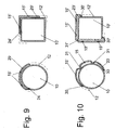
- Fig. 9 forms a rolling profile using a passage 26 and a compression 27 within the planes of a tube sheet 8; 8 'and corresponding to a flow tray 9; 9 'a heat transfer profile 10' from.
- the closure 24 defines a longitudinal gap 28 which is connected to the nonwoven layers 13; 13 'communicates.
- both the heat carrier profile 10 'and the working means guide 16' is manufactured by low-pressure roll forming from a single blank of a flat material.
- the closure 24 ' can be omitted;
- Fig. 9 is made of a single blank of a flat material an approximately S-shaped roll profile such by roll forming that two approximately circular segment-shaped and unequal segments are formed, which include a chordal, approximately planar profiled web inside and with their peripheral rounding in two approximately semi-circular pass over peripheral structures.
- the larger structure represents an approximated semicircular heat transfer profile 10 ', the liquid and gas tight in the tube sheets 8; 8 'is used with a peripheral approximately semicircular boundary.
- the closures 24; 24 ' limit the length of the heat carrier profile only in the vicinity of the tube sheets 8; 8 'in the form of a short longitudinal seam, a total of an open longitudinal gap 28 ausformend.
- the smaller structure represents an inner working means guide (16 ').
- Two roll-formed tabs 29; 29 ' are located only above or below the flow floors 9; 9 '. However, these are not necessarily tight with their upper periphery in the flow trays 9; 9 'integrated, only with the gap-like outlet opening of the flags 29; 29 'is this in the nonwoven layers 13; 13 'via the stomata 12; 12 'directed into the sorbent bed 14.
- This design of this roll profile in its more complicated form, represents a preferred variant for the production of heat transfer tubes 10 'of larger dimensions, which are combined with working means guides 16, 16 '.
- This version is preferred for heat storage 1 with a high height / diameter ratio of at least 5.
- Fig. 9 are formed from a single blank of a sheet of heat transfer tubes 10 and heat transfer profiles 10 'by roll forming.
- Material-identical flags 29; 29 'from the flat material form the working means guides 16; 16 'with the openings 15; 15 'intermediate in both planes in the middle of the tube sheets 8; 8 'and the flow floors 9; 9 'and within the nonwoven layers 13 lying out.
- the closures 24; 24 ' ensure the tightness of the heat transfer tubes 10 and the heat transfer profiles 10' within the tube sheets 8; 8th'.
- the flags 29; 29 ' are at the gap formations largely close to the flow bottoms 9; 9 'to the stomata 12; 12 'formed.
- the corresponding cross sections of the distances are those of the stomata 12; 12 'by means of beads 27; 27 'optimally adapted.
- brackets 23; 23 ' are as described in Example 6, if necessary, easily interchangeable and audit friendly.
- the sorbent bed 14 is divided in portions into sack-like containers consisting of metal wire and introduced into the heat store 1 between a reduced number of heat carrier tubes 10 or heat carrier profiles 10 '.
- the filling proportion of sorbent increases within an additional free space.
- the heat conduction within the sorbent bed 14 is increased due to the formation of thermal bridges created beyond due to better thermal contact between the containers.
- the heat storage 1 in terms of a compact heat storage after DE 199 63 322 A1 at least one tank for the evaporation and at least one for the condensation of the working fluid and represents from both, similarly designed, a common device.
- the heat storage 1 is in a modification of Examples 1 to 16 in a horizontal or obliquely inclined arrangement with horizontally or obliquely oriented tube sheets 8; 8 ', flow floors 9; 9 'and nonwoven layers 13; 13 'used.
Landscapes
- Engineering & Computer Science (AREA)
- Physics & Mathematics (AREA)
- Thermal Sciences (AREA)
- Mechanical Engineering (AREA)
- General Engineering & Computer Science (AREA)
- Chemical & Material Sciences (AREA)
- Chemical Kinetics & Catalysis (AREA)
- General Chemical & Material Sciences (AREA)
- Sorption Type Refrigeration Machines (AREA)
- Thermotherapy And Cooling Therapy Devices (AREA)
- Building Environments (AREA)
Priority Applications (1)
| Application Number | Priority Date | Filing Date | Title |
|---|---|---|---|
| PL06763673T PL1896791T3 (pl) | 2005-06-13 | 2006-06-13 | Akumulator energii cieplnej o wysokiej gęstości magazynowania |
Applications Claiming Priority (3)
| Application Number | Priority Date | Filing Date | Title |
|---|---|---|---|
| DE102005000075A DE102005000075A1 (de) | 2005-06-13 | 2005-06-13 | Wärmespeicher hoher Speicherdichte |
| DE102005051574 | 2005-10-21 | ||
| PCT/EP2006/063148 WO2006134107A1 (de) | 2005-06-13 | 2006-06-13 | Wärmespeicher hoher speicherdichte |
Publications (2)
| Publication Number | Publication Date |
|---|---|
| EP1896791A1 EP1896791A1 (de) | 2008-03-12 |
| EP1896791B1 true EP1896791B1 (de) | 2011-09-28 |
Family
ID=37057933
Family Applications (1)
| Application Number | Title | Priority Date | Filing Date |
|---|---|---|---|
| EP06763673A Not-in-force EP1896791B1 (de) | 2005-06-13 | 2006-06-13 | Wärmespeicher hoher speicherdichte |
Country Status (5)
| Country | Link |
|---|---|
| EP (1) | EP1896791B1 (pl) |
| AT (1) | ATE526549T1 (pl) |
| ES (1) | ES2378965T3 (pl) |
| PL (1) | PL1896791T3 (pl) |
| WO (1) | WO2006134107A1 (pl) |
Families Citing this family (3)
| Publication number | Priority date | Publication date | Assignee | Title |
|---|---|---|---|---|
| JP5348237B2 (ja) * | 2009-02-19 | 2013-11-20 | 富士通株式会社 | ヒートポンプ |
| EP3299759A1 (en) * | 2016-09-21 | 2018-03-28 | Nederlandse Organisatie voor toegepast- natuurwetenschappelijk onderzoek TNO | System and method for thermochemical storage of energy |
| FR3100876B1 (fr) * | 2019-09-12 | 2021-09-03 | Ifp Energies Now | Dispositif multitubulaire de stockage thermique par sorption sur zéolithe par contact direct |
Family Cites Families (4)
| Publication number | Priority date | Publication date | Assignee | Title |
|---|---|---|---|---|
| JPH0391660A (ja) * | 1989-09-04 | 1991-04-17 | Nishiyodo Kuuchiyouki Kk | 吸着式蓄熱装置及び該装置を利用した吸着式蓄熱システム |
| DE19735007C1 (de) * | 1997-08-13 | 1999-01-28 | Winkelmann & Pannhoff Gmbh & C | Vorrichtung zur Speicherung und Abgabe von Wärme |
| DE19811302C2 (de) * | 1997-08-13 | 1999-12-09 | Ufe Solar Gmbh | Sorptionsspeicher, Anordnung und Verfahren zur Speicherung von Wärme |
| DE19963322B4 (de) * | 1999-12-21 | 2005-09-29 | Bernd Füsting | Sorptionswärmespeicher hoher Energiedichte |
-
2006
- 2006-06-13 EP EP06763673A patent/EP1896791B1/de not_active Not-in-force
- 2006-06-13 AT AT06763673T patent/ATE526549T1/de active
- 2006-06-13 PL PL06763673T patent/PL1896791T3/pl unknown
- 2006-06-13 WO PCT/EP2006/063148 patent/WO2006134107A1/de not_active Ceased
- 2006-06-13 ES ES06763673T patent/ES2378965T3/es active Active
Also Published As
| Publication number | Publication date |
|---|---|
| PL1896791T3 (pl) | 2012-05-31 |
| WO2006134107A1 (de) | 2006-12-21 |
| EP1896791A1 (de) | 2008-03-12 |
| ATE526549T1 (de) | 2011-10-15 |
| ES2378965T3 (es) | 2012-04-19 |
Similar Documents
| Publication | Publication Date | Title |
|---|---|---|
| DE102008048655B4 (de) | Verfahren zum Transport von Wärme, Transportsystem für einen Wärmeträger sowie dessen Verwendung | |
| DE3408192C2 (de) | Verfahren zum Hochtransformieren der Temperatur von Wärme sowie Wärmetransformator | |
| DE19963322B4 (de) | Sorptionswärmespeicher hoher Energiedichte | |
| DE102020007211A1 (de) | Adsorptionskältevorrichtung und Verfahren zum Erzeugen von Adsorptionskälte aus Wärme | |
| EP2643645B1 (de) | Adsorptionskältemaschine mit einem Vakuumbehälter zur Entfernung von Fremdgasen | |
| DE10063067B4 (de) | Wasserstoff-Okklusionskern | |
| EP2414746A2 (de) | Arbeitsmittelspeicher, wärmeübertrager und wärmepumpe | |
| EP1896791B1 (de) | Wärmespeicher hoher speicherdichte | |
| DE112015005092B4 (de) | Chemische Wärmepumpe | |
| DE2622699C3 (pl) | ||
| DE3408193C2 (de) | Verfahren zum Erhöhen der Temperatur von Wärme durch einen Wärmepumpenprozeß | |
| DE19908666A1 (de) | Sorptionswärmepumpe/-Kältemaschine mit Erwärmung des bisherigen Adsorbers auf Desorptionstemperatur durch Adsorption | |
| DE10047503A1 (de) | Sorptionsreaktor | |
| DE102005000075A1 (de) | Wärmespeicher hoher Speicherdichte | |
| DE102008023662A1 (de) | Wärmepumpe | |
| DE112017003771T5 (de) | Wärmespeichersystem, Wärmespeicherbehälter, den Wärmespeicherbehälter verwendende Wärmespeichervorrichtung und die Wärmespeichervorrichtung verwendende Wärmevorrichtung | |
| DE102009043515A1 (de) | Solarthermisch betriebene Adsorptionskältemaschine zur Raumklimatisierung und Lebensmittelkühlung | |
| EP1004001B1 (de) | Sorptionsspeicher, anordnung und verfahren zur speicherung von wärme | |
| DE102015214374A1 (de) | Adsorptionswärmepumpe mit Plattenwärmetauscher | |
| EP1150077B1 (de) | Sorptionsbehälter-Anordnung mit flexibler Hülle | |
| DE102004059098A1 (de) | Energiecontainer hoher Energiedichte und Verfahren zur Betreibung | |
| EP2911916B1 (de) | Verbessertes wärmeabschirmsystem | |
| EP2567161A2 (de) | Selbststabilisierende trennwand mit erhöhter thermischer isolation für unterdruckbehälter | |
| DE102011108467B4 (de) | Adsorptionswärmeübertragermodul sowie eine Adsorptionswärmeübertrageranordnung | |
| AT413594B (de) | Einrichtung zum erwärmen eines flüssigen wärmeträgermediums |
Legal Events
| Date | Code | Title | Description |
|---|---|---|---|
| PUAI | Public reference made under article 153(3) epc to a published international application that has entered the european phase |
Free format text: ORIGINAL CODE: 0009012 |
|
| 17P | Request for examination filed |
Effective date: 20080111 |
|
| AK | Designated contracting states |
Kind code of ref document: A1 Designated state(s): AT BE BG CH CY CZ DE DK EE ES FI FR GB GR HU IE IS IT LI LT LU LV MC NL PL PT RO SE SI SK TR |
|
| DAX | Request for extension of the european patent (deleted) | ||
| RIN1 | Information on inventor provided before grant (corrected) |
Inventor name: STACH, HELMUT Inventor name: MUENN, PETER Inventor name: FUESTING, BERND |
|
| DAX | Request for extension of the european patent (deleted) | ||
| GRAP | Despatch of communication of intention to grant a patent |
Free format text: ORIGINAL CODE: EPIDOSNIGR1 |
|
| RAP1 | Party data changed (applicant data changed or rights of an application transferred) |
Owner name: PBB GBR |
|
| GRAS | Grant fee paid |
Free format text: ORIGINAL CODE: EPIDOSNIGR3 |
|
| GRAA | (expected) grant |
Free format text: ORIGINAL CODE: 0009210 |
|
| AK | Designated contracting states |
Kind code of ref document: B1 Designated state(s): AT BE BG CH CY CZ DE DK EE ES FI FR GB GR HU IE IS IT LI LT LU LV MC NL PL PT RO SE SI SK TR |
|
| REG | Reference to a national code |
Ref country code: GB Ref legal event code: FG4D Free format text: NOT ENGLISH |
|
| REG | Reference to a national code |
Ref country code: CH Ref legal event code: EP |
|
| REG | Reference to a national code |
Ref country code: IE Ref legal event code: FG4D |
|
| REG | Reference to a national code |
Ref country code: DE Ref legal event code: R096 Ref document number: 502006010274 Country of ref document: DE Effective date: 20111124 |
|
| REG | Reference to a national code |
Ref country code: NL Ref legal event code: VDEP Effective date: 20110928 |
|
| REG | Reference to a national code |
Ref country code: SE Ref legal event code: TRGR |
|
| PG25 | Lapsed in a contracting state [announced via postgrant information from national office to epo] |
Ref country code: FI Free format text: LAPSE BECAUSE OF FAILURE TO SUBMIT A TRANSLATION OF THE DESCRIPTION OR TO PAY THE FEE WITHIN THE PRESCRIBED TIME-LIMIT Effective date: 20110928 |
|
| PG25 | Lapsed in a contracting state [announced via postgrant information from national office to epo] |
Ref country code: SI Free format text: LAPSE BECAUSE OF FAILURE TO SUBMIT A TRANSLATION OF THE DESCRIPTION OR TO PAY THE FEE WITHIN THE PRESCRIBED TIME-LIMIT Effective date: 20110928 Ref country code: LV Free format text: LAPSE BECAUSE OF FAILURE TO SUBMIT A TRANSLATION OF THE DESCRIPTION OR TO PAY THE FEE WITHIN THE PRESCRIBED TIME-LIMIT Effective date: 20110928 Ref country code: CY Free format text: LAPSE BECAUSE OF FAILURE TO SUBMIT A TRANSLATION OF THE DESCRIPTION OR TO PAY THE FEE WITHIN THE PRESCRIBED TIME-LIMIT Effective date: 20110928 Ref country code: GR Free format text: LAPSE BECAUSE OF FAILURE TO SUBMIT A TRANSLATION OF THE DESCRIPTION OR TO PAY THE FEE WITHIN THE PRESCRIBED TIME-LIMIT Effective date: 20111229 |
|
| REG | Reference to a national code |
Ref country code: ES Ref legal event code: FG2A Ref document number: 2378965 Country of ref document: ES Kind code of ref document: T3 Effective date: 20120419 |
|
| REG | Reference to a national code |
Ref country code: IE Ref legal event code: FD4D |
|
| PG25 | Lapsed in a contracting state [announced via postgrant information from national office to epo] |
Ref country code: IS Free format text: LAPSE BECAUSE OF FAILURE TO SUBMIT A TRANSLATION OF THE DESCRIPTION OR TO PAY THE FEE WITHIN THE PRESCRIBED TIME-LIMIT Effective date: 20120128 |
|
| REG | Reference to a national code |
Ref country code: SK Ref legal event code: T3 Ref document number: E 11201 Country of ref document: SK |
|
| PG25 | Lapsed in a contracting state [announced via postgrant information from national office to epo] |
Ref country code: NL Free format text: LAPSE BECAUSE OF FAILURE TO SUBMIT A TRANSLATION OF THE DESCRIPTION OR TO PAY THE FEE WITHIN THE PRESCRIBED TIME-LIMIT Effective date: 20110928 Ref country code: RO Free format text: LAPSE BECAUSE OF FAILURE TO SUBMIT A TRANSLATION OF THE DESCRIPTION OR TO PAY THE FEE WITHIN THE PRESCRIBED TIME-LIMIT Effective date: 20110928 Ref country code: EE Free format text: LAPSE BECAUSE OF FAILURE TO SUBMIT A TRANSLATION OF THE DESCRIPTION OR TO PAY THE FEE WITHIN THE PRESCRIBED TIME-LIMIT Effective date: 20110928 Ref country code: PT Free format text: LAPSE BECAUSE OF FAILURE TO SUBMIT A TRANSLATION OF THE DESCRIPTION OR TO PAY THE FEE WITHIN THE PRESCRIBED TIME-LIMIT Effective date: 20120130 |
|
| REG | Reference to a national code |
Ref country code: PL Ref legal event code: T3 |
|
| PG25 | Lapsed in a contracting state [announced via postgrant information from national office to epo] |
Ref country code: DK Free format text: LAPSE BECAUSE OF FAILURE TO SUBMIT A TRANSLATION OF THE DESCRIPTION OR TO PAY THE FEE WITHIN THE PRESCRIBED TIME-LIMIT Effective date: 20110928 Ref country code: IE Free format text: LAPSE BECAUSE OF FAILURE TO SUBMIT A TRANSLATION OF THE DESCRIPTION OR TO PAY THE FEE WITHIN THE PRESCRIBED TIME-LIMIT Effective date: 20110928 |
|
| PLBE | No opposition filed within time limit |
Free format text: ORIGINAL CODE: 0009261 |
|
| STAA | Information on the status of an ep patent application or granted ep patent |
Free format text: STATUS: NO OPPOSITION FILED WITHIN TIME LIMIT |
|
| 26N | No opposition filed |
Effective date: 20120629 |
|
| REG | Reference to a national code |
Ref country code: DE Ref legal event code: R097 Ref document number: 502006010274 Country of ref document: DE Effective date: 20120629 |
|
| PG25 | Lapsed in a contracting state [announced via postgrant information from national office to epo] |
Ref country code: MC Free format text: LAPSE BECAUSE OF NON-PAYMENT OF DUE FEES Effective date: 20120630 |
|
| PG25 | Lapsed in a contracting state [announced via postgrant information from national office to epo] |
Ref country code: IT Free format text: LAPSE BECAUSE OF NON-PAYMENT OF DUE FEES Effective date: 20120613 |
|
| PG25 | Lapsed in a contracting state [announced via postgrant information from national office to epo] |
Ref country code: BG Free format text: LAPSE BECAUSE OF FAILURE TO SUBMIT A TRANSLATION OF THE DESCRIPTION OR TO PAY THE FEE WITHIN THE PRESCRIBED TIME-LIMIT Effective date: 20111228 |
|
| PG25 | Lapsed in a contracting state [announced via postgrant information from national office to epo] |
Ref country code: LU Free format text: LAPSE BECAUSE OF NON-PAYMENT OF DUE FEES Effective date: 20120613 |
|
| PG25 | Lapsed in a contracting state [announced via postgrant information from national office to epo] |
Ref country code: HU Free format text: LAPSE BECAUSE OF FAILURE TO SUBMIT A TRANSLATION OF THE DESCRIPTION OR TO PAY THE FEE WITHIN THE PRESCRIBED TIME-LIMIT Effective date: 20060613 |
|
| REG | Reference to a national code |
Ref country code: FR Ref legal event code: PLFP Year of fee payment: 11 |
|
| REG | Reference to a national code |
Ref country code: FR Ref legal event code: PLFP Year of fee payment: 12 |
|
| PGFP | Annual fee paid to national office [announced via postgrant information from national office to epo] |
Ref country code: LU Payment date: 20170425 Year of fee payment: 11 |
|
| REG | Reference to a national code |
Ref country code: FR Ref legal event code: PLFP Year of fee payment: 13 |
|
| PG25 | Lapsed in a contracting state [announced via postgrant information from national office to epo] |
Ref country code: PL Free format text: LAPSE BECAUSE OF NON-PAYMENT OF DUE FEES Effective date: 20180613 |
|
| PGFP | Annual fee paid to national office [announced via postgrant information from national office to epo] |
Ref country code: TR Payment date: 20201102 Year of fee payment: 15 |
|
| REG | Reference to a national code |
Ref country code: DE Ref legal event code: R119 Ref document number: 502006010274 Country of ref document: DE |
|
| PGFP | Annual fee paid to national office [announced via postgrant information from national office to epo] |
Ref country code: ES Payment date: 20201027 Year of fee payment: 15 Ref country code: LT Payment date: 20201029 Year of fee payment: 15 Ref country code: FR Payment date: 20201023 Year of fee payment: 15 Ref country code: CZ Payment date: 20201102 Year of fee payment: 15 |
|
| PGFP | Annual fee paid to national office [announced via postgrant information from national office to epo] |
Ref country code: SK Payment date: 20201102 Year of fee payment: 15 Ref country code: BE Payment date: 20201023 Year of fee payment: 15 |
|
| PG25 | Lapsed in a contracting state [announced via postgrant information from national office to epo] |
Ref country code: DE Free format text: LAPSE BECAUSE OF NON-PAYMENT OF DUE FEES Effective date: 20210101 |
|
| REG | Reference to a national code |
Ref country code: DE Ref legal event code: R073 Ref document number: 502006010274 Country of ref document: DE |
|
| REG | Reference to a national code |
Ref country code: DE Ref legal event code: R074 Ref document number: 502006010274 Country of ref document: DE |
|
| REG | Reference to a national code |
Ref country code: LT Ref legal event code: MM4D |
|
| PG25 | Lapsed in a contracting state [announced via postgrant information from national office to epo] |
Ref country code: CZ Free format text: LAPSE BECAUSE OF NON-PAYMENT OF DUE FEES Effective date: 20210613 Ref country code: DE Free format text: LAPSE BECAUSE OF NON-PAYMENT OF DUE FEES Effective date: 20210101 |
|
| PGFP | Annual fee paid to national office [announced via postgrant information from national office to epo] |
Ref country code: GB Payment date: 20211220 Year of fee payment: 16 Ref country code: SE Payment date: 20211222 Year of fee payment: 16 Ref country code: DE Payment date: 20211228 Year of fee payment: 16 Ref country code: AT Payment date: 20211221 Year of fee payment: 16 |
|
| PGRI | Patent reinstated in contracting state [announced from national office to epo] |
Ref country code: DE Effective date: 20211223 |
|
| REG | Reference to a national code |
Ref country code: SK Ref legal event code: MM4A Ref document number: E 11201 Country of ref document: SK Effective date: 20210613 |
|
| PGFP | Annual fee paid to national office [announced via postgrant information from national office to epo] |
Ref country code: CH Payment date: 20211222 Year of fee payment: 16 |
|
| REG | Reference to a national code |
Ref country code: BE Ref legal event code: MM Effective date: 20210630 |
|
| PG25 | Lapsed in a contracting state [announced via postgrant information from national office to epo] |
Ref country code: LT Free format text: LAPSE BECAUSE OF NON-PAYMENT OF DUE FEES Effective date: 20210613 |
|
| PG25 | Lapsed in a contracting state [announced via postgrant information from national office to epo] |
Ref country code: SK Free format text: LAPSE BECAUSE OF NON-PAYMENT OF DUE FEES Effective date: 20210613 Ref country code: FR Free format text: LAPSE BECAUSE OF NON-PAYMENT OF DUE FEES Effective date: 20210630 |
|
| PG25 | Lapsed in a contracting state [announced via postgrant information from national office to epo] |
Ref country code: TR Free format text: LAPSE BECAUSE OF NON-PAYMENT OF DUE FEES Effective date: 20210613 |
|
| PG25 | Lapsed in a contracting state [announced via postgrant information from national office to epo] |
Ref country code: BE Free format text: LAPSE BECAUSE OF NON-PAYMENT OF DUE FEES Effective date: 20210630 |
|
| REG | Reference to a national code |
Ref country code: ES Ref legal event code: FD2A Effective date: 20220826 |
|
| PG25 | Lapsed in a contracting state [announced via postgrant information from national office to epo] |
Ref country code: ES Free format text: LAPSE BECAUSE OF NON-PAYMENT OF DUE FEES Effective date: 20210614 |
|
| REG | Reference to a national code |
Ref country code: DE Ref legal event code: R119 Ref document number: 502006010274 Country of ref document: DE |
|
| REG | Reference to a national code |
Ref country code: CH Ref legal event code: PL Ref country code: SE Ref legal event code: EUG |
|
| REG | Reference to a national code |
Ref country code: AT Ref legal event code: MM01 Ref document number: 526549 Country of ref document: AT Kind code of ref document: T Effective date: 20220613 |
|
| GBPC | Gb: european patent ceased through non-payment of renewal fee |
Effective date: 20220613 |
|
| PG25 | Lapsed in a contracting state [announced via postgrant information from national office to epo] |
Ref country code: SE Free format text: LAPSE BECAUSE OF NON-PAYMENT OF DUE FEES Effective date: 20220614 Ref country code: LI Free format text: LAPSE BECAUSE OF NON-PAYMENT OF DUE FEES Effective date: 20220630 Ref country code: CH Free format text: LAPSE BECAUSE OF NON-PAYMENT OF DUE FEES Effective date: 20220630 Ref country code: AT Free format text: LAPSE BECAUSE OF NON-PAYMENT OF DUE FEES Effective date: 20220613 |
|
| PG25 | Lapsed in a contracting state [announced via postgrant information from national office to epo] |
Ref country code: GB Free format text: LAPSE BECAUSE OF NON-PAYMENT OF DUE FEES Effective date: 20220613 Ref country code: DE Free format text: LAPSE BECAUSE OF NON-PAYMENT OF DUE FEES Effective date: 20230103 |