EP1896347B1 - Low back pressure module with l-shaped intermediate support - Google Patents
Low back pressure module with l-shaped intermediate support Download PDFInfo
- Publication number
- EP1896347B1 EP1896347B1 EP06741599A EP06741599A EP1896347B1 EP 1896347 B1 EP1896347 B1 EP 1896347B1 EP 06741599 A EP06741599 A EP 06741599A EP 06741599 A EP06741599 A EP 06741599A EP 1896347 B1 EP1896347 B1 EP 1896347B1
- Authority
- EP
- European Patent Office
- Prior art keywords
- shaft
- belt
- disposed
- side wall
- intermediate support
- Prior art date
- Legal status (The legal status is an assumption and is not a legal conclusion. Google has not performed a legal analysis and makes no representation as to the accuracy of the status listed.)
- Not-in-force
Links
Images


Classifications
-
- B—PERFORMING OPERATIONS; TRANSPORTING
- B65—CONVEYING; PACKING; STORING; HANDLING THIN OR FILAMENTARY MATERIAL
- B65G—TRANSPORT OR STORAGE DEVICES, e.g. CONVEYORS FOR LOADING OR TIPPING, SHOP CONVEYOR SYSTEMS OR PNEUMATIC TUBE CONVEYORS
- B65G17/00—Conveyors having an endless traction element, e.g. a chain, transmitting movement to a continuous or substantially-continuous load-carrying surface or to a series of individual load-carriers; Endless-chain conveyors in which the chains form the load-carrying surface
- B65G17/30—Details; Auxiliary devices
- B65G17/32—Individual load-carriers
-
- B—PERFORMING OPERATIONS; TRANSPORTING
- B65—CONVEYING; PACKING; STORING; HANDLING THIN OR FILAMENTARY MATERIAL
- B65G—TRANSPORT OR STORAGE DEVICES, e.g. CONVEYORS FOR LOADING OR TIPPING, SHOP CONVEYOR SYSTEMS OR PNEUMATIC TUBE CONVEYORS
- B65G17/00—Conveyors having an endless traction element, e.g. a chain, transmitting movement to a continuous or substantially-continuous load-carrying surface or to a series of individual load-carriers; Endless-chain conveyors in which the chains form the load-carrying surface
- B65G17/06—Conveyors having an endless traction element, e.g. a chain, transmitting movement to a continuous or substantially-continuous load-carrying surface or to a series of individual load-carriers; Endless-chain conveyors in which the chains form the load-carrying surface having a load-carrying surface formed by a series of interconnected, e.g. longitudinal, links, plates, or platforms
- B65G17/08—Conveyors having an endless traction element, e.g. a chain, transmitting movement to a continuous or substantially-continuous load-carrying surface or to a series of individual load-carriers; Endless-chain conveyors in which the chains form the load-carrying surface having a load-carrying surface formed by a series of interconnected, e.g. longitudinal, links, plates, or platforms the surface being formed by the traction element
-
- B—PERFORMING OPERATIONS; TRANSPORTING
- B65—CONVEYING; PACKING; STORING; HANDLING THIN OR FILAMENTARY MATERIAL
- B65G—TRANSPORT OR STORAGE DEVICES, e.g. CONVEYORS FOR LOADING OR TIPPING, SHOP CONVEYOR SYSTEMS OR PNEUMATIC TUBE CONVEYORS
- B65G17/00—Conveyors having an endless traction element, e.g. a chain, transmitting movement to a continuous or substantially-continuous load-carrying surface or to a series of individual load-carriers; Endless-chain conveyors in which the chains form the load-carrying surface
- B65G17/30—Details; Auxiliary devices
- B65G17/38—Chains or like traction elements; Connections between traction elements and load-carriers
- B65G17/40—Chains acting as load-carriers
Definitions
- This invention relates to conveyor belts and, more particularly, to modular plastic conveyor belts formed of rows of plastic belt modules pivotally interlinked by transverse pivot rods.
- U.S. Patent No. 4,909,380 discloses a solution to backline pressure that includes providing shafts mounted above the top surface of belt modules. Each shaft carries a plurality of rollers forming a low back pressure conveying surface. The patent also discloses the use of an intermediate support for the.shaft that permits the use of a smaller diameter shaft for wider belt modules thereby conserving material and reducing cost.
- the intermediate support shown in the '380 patent is an upstanding wall having slot-like indentations in the top surface adapted to receive and support the shafts as best shown in Fig. 4 .
- the slot-like indentations are narrow and completely surround the shaft making them difficult to clean without removing the shafts and therefore these indentations may lead to unsanitary conditions in food conveying applications.
- the present invention meets the above-described need by providing a belt module according to independent claim 1. Preferred embodiments will emerge from the dependent claims.
- a belt module comprises a base portion having a first end, a second end, and an intermediate section extending in a transverse direction from the first end to the second end.
- the module includes a first plurality of link ends extending from the intermediate section in a direction of belt travel substantially perpendicular to the transverse direction.
- Each of the first plurality of link ends have first openings that are aligned in the transverse direction.
- the module includes a second plurality of link ends extending from the intermediate section in a direction opposite to the first link ends.
- the second plurality of link ends each have second openings aligned in the transverse direction.
- a first intermediate support is disposed in spaced apart relation to the first end of the base portion.
- the first intermediate support has a first side wall and a second side wall.
- the first side wall has a length that is greater than the length of the second side wall.
- the first intermediate support has a shaft support surface disposed between the first side wall and the second side wall such that the shaft support surface supports one side of a shaft in the direction of belt travel, but not the side of the shaft opposite to this side.
- a second intermediate support has a first side wall and a second side wall.
- the first side wall has a length that is greater than the second side wall.
- the second intermediate support has a shaft support surface disposed between the first side wall and the second side wall. The second intermediate support is offset from the first intermediate support in the transverse direction and is disposed in facing relation to the first intermediate support.
- the first and second intermediate support provide complementary support to both sides of the shaft, but due to the offset arrangement in the transverse direction the shaft is open for cleaning and there is less chance for any debris to accumulate around the shaft.
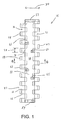
- Fig. 1 is a top plan view of a low back pressure belt module according to the present invention with the shafts and rollers removed for clarity;
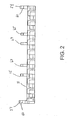
- Fig. 2 is a side elevational view of the belt module shown in Fig. 1 ;
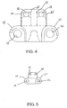
- Fig. 4 is an end elevational view of the belt module including the shafts;
- Fig. 6 is a cross-sectional view taken along lines 6-6 of Fig. 1 ;
- Fig. 7 is an enlarged view of a portion of the module shown in Fig. 6 ;
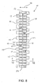
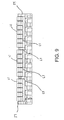
- Fig. 9 is a side elevational view of the belt module shown in Fig. 8 ;
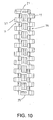
- Fig. 10 is a bottom plan view of the belt module of Fig. 8 ;
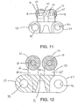
- Fig. 12 is a cross-sectional view taken along lines 12-12 of Fig. 8 .
- the shown embodiment of the low back pressure belt module 15 of the present invention includes a pair of shafts 18 supported above the top surface of the module 15.
- the shafts 18 support a plurality of rollers 21 to provide a low friction conveying surface.
- the module 15 has a first plurality of link ends 24 and a second plurality of link ends 27 disposed opposite from the first link ends 24.
- the first plurality of link ends 24 have opposed side walls 25, 26 that provide a transverse thickness 28 connected to an intermediate section 48 at a first proximal portion 31 ( Fig. 1 ).
- the transverse thickness 28 extends in a direction of belt travel 30 from the intermediate section 48 to a first distal portion 29.
- the second plurality of link ends 27 have similar geometry except they extend opposite to each other in the direction of belt travel indicated by arrow 30.
- the belt module 15 may be driven in either direction along arrow 30.
- module 15 is formed out of plastic or other materials suitable for many applications including conveying of food products.
- the material should be lightweight, non-corrosive, and easily cleaned.
- the module 15 is thermoformed from a plastic resin raw material as known to those of ordinary skill.in the art.
- the module 15 has a base portion 47 with an intermediate section 48 extending between first and second link ends 24, 27.
- Intermediate section 48 has an upper deck surface 51 having a substantially rectangular shape in plan view.
- shaft support members 54 and 57 extend upward from the intermediate section 48.
- the shaft support members 54, 57 have openings 60 for receiving and supporting the ends of the shafts 18.
- the openings 60 comprise a circular bore formed in the shaft support members 54, 57 and are bounded by a curved inner wall having a diameter slightly larger than the diameter of the shaft 18.
- Each opening 60 supports one of the shafts 18 and the shafts are preferably fixed by at least one knurled shaft end.
- Intermediate shaft support members 63, 65 extend upward from the upper surface 51 of module 15.
- the intermediate shaft support members 63, 65 are disposed in two rows along the intermediate section 48 in the transverse direction.
- intermediate shaft support member 63 has an L-shaped "left-hand" configuration with an outer wall 66 facing the outside of the module 15.
- the outer wall 66 extends from the upper surface 51 to a top surface 69.
- the member 63 extends downward along a curved shaft support surface 72 for receiving the shaft 18.
- the curved shaft support surface 72 extends to portion 74 extending to an inner wall 75 disposed toward the middle of the intermediate section 48.
- intermediate shaft support member 65 has a "right-hand” configuration that is also L-shaped but is a mirror image of the intermediate shaft support member 63.
- Intermediate shaft support member 65 has an outer wall 78 that is substantially perpendicular to the top surface 51 of module 15. The outer wall 78 extends upward from the surface 51 until it reaches a top surface 81.
- Surface 81 extends to a curved shaft support surface 84 that receives the shaft 18.
- Curved shaft support surface 84 extends to portion 87 which in turn extends to the top portion of an inner wall 90 disposed toward the middle of the intermediate section 48.
- the mirror-imaged, L-shaped intermediate shaft support members 63 and 65 are aligned in the transverse direction with the openings 60 in the shaft support members 54 and 57 such that the shaft 18 is supported by each of the intermediate shaft support members 63, 65.
- the curved shaft support surfaces 72 and 84 align in the transverse direction such that opposite sides of the shaft 18 are supported as best shown in Fig. 4 . Because the curved openings are aligned in the transverse direction with regard to the sides of the shaft 18, the intermediate shaft support members 63, 65 provide excellent support for the shaft 18.
- the arrangement of the intermediate support members 63, 65 in mirrored relation provides complementary support for opposite sides of the shaft 18.
- the staggered arrangement of the "left-hand” and “right-hand” shaft support members provides an open configuration with access to the shaft for cleaning and without a narrow slot for debris to accumulate.
- a single intermediate shaft support member 63 may be used in instances where the shaft support members 54, 57 are close enough to provide sufficient additional support.
Landscapes
- Engineering & Computer Science (AREA)
- Mechanical Engineering (AREA)
- Structure Of Belt Conveyors (AREA)
- Belt Conveyors (AREA)
- Coupling Device And Connection With Printed Circuit (AREA)
- Chain Conveyers (AREA)
- Transition And Organic Metals Composition Catalysts For Addition Polymerization (AREA)
- Pharmaceuticals Containing Other Organic And Inorganic Compounds (AREA)
- Fats And Perfumes (AREA)
- Package Frames And Binding Bands (AREA)
Applications Claiming Priority (2)
| Application Number | Priority Date | Filing Date | Title |
|---|---|---|---|
| US11/137,021 US7073659B1 (en) | 2005-05-25 | 2005-05-25 | Low back pressure module with L-shaped intermediate support |
| PCT/CH2006/000264 WO2006125331A1 (en) | 2005-05-25 | 2006-05-19 | Low back pressure module with l-shaped intermediate support |
Publications (2)
| Publication Number | Publication Date |
|---|---|
| EP1896347A1 EP1896347A1 (en) | 2008-03-12 |
| EP1896347B1 true EP1896347B1 (en) | 2008-10-15 |
Family
ID=36643964
Family Applications (1)
| Application Number | Title | Priority Date | Filing Date |
|---|---|---|---|
| EP06741599A Not-in-force EP1896347B1 (en) | 2005-05-25 | 2006-05-19 | Low back pressure module with l-shaped intermediate support |
Country Status (10)
| Country | Link |
|---|---|
| US (1) | US7073659B1 (ja) |
| EP (1) | EP1896347B1 (ja) |
| JP (1) | JP2008542149A (ja) |
| CN (1) | CN101180228A (ja) |
| AT (1) | ATE411241T1 (ja) |
| CA (1) | CA2605755A1 (ja) |
| DE (1) | DE602006003223D1 (ja) |
| DK (1) | DK1896347T3 (ja) |
| ES (1) | ES2316068T3 (ja) |
| WO (1) | WO2006125331A1 (ja) |
Families Citing this family (5)
| Publication number | Priority date | Publication date | Assignee | Title |
|---|---|---|---|---|
| ES2386671T3 (es) * | 2008-03-28 | 2012-08-24 | Ammeraal Beltech Modular A/S | Módulo de eslabón de cadena para cadena de acumulación |
| US7891481B2 (en) * | 2008-09-11 | 2011-02-22 | Laitram, L.L.C. | Conveyor belt for mounting oblique rollers on lateral rods |
| DE102012104891B4 (de) | 2012-06-05 | 2024-03-28 | Krones Aktiengesellschaft | Mehrgliedriger Fördergurt mit Laufrollen |
| CA2897374A1 (en) | 2013-01-08 | 2014-07-17 | Solus Industrial Innovations, Llc | Modular conveying systems and methods |
| IT202000017068A1 (it) | 2020-07-14 | 2022-01-14 | Regina Catene Calibrate Spa | Modulo di tappeto trasportatore modulare con superficie di trasporto a rulli e tappeto trasportatore modulare formato da una pluralita’ di tali moduli. |
Family Cites Families (11)
| Publication number | Priority date | Publication date | Assignee | Title |
|---|---|---|---|---|
| US4271960A (en) | 1978-11-20 | 1981-06-09 | Taylor Manufacturing Company | Conveyors and chain |
| US5096050A (en) | 1981-06-02 | 1992-03-17 | Rexnord Corporation | Low backline pressure chain |
| US5330045A (en) | 1981-06-02 | 1994-07-19 | Rexnord Corporation | Low backline pressure chain |
| EP0152639B1 (en) | 1982-02-22 | 1988-02-10 | Rexnord Inc. | Low backline pressure chain |
| US5143205A (en) | 1986-05-13 | 1992-09-01 | Enuma Chain Manufacturing Co., Ltd. | Free-flow conveyor chain |
| GB8615874D0 (en) | 1986-06-28 | 1986-08-06 | Automotive Prod Plc | Friction material & carrier plate assembly |
| US4880107A (en) * | 1987-07-31 | 1989-11-14 | Rexnord Corporation | Table top chain link with rib |
| US4821869A (en) * | 1987-11-23 | 1989-04-18 | Rexnord Inc. | Low backline pressure chain for use with transfer plate |
| US5224583A (en) * | 1990-10-09 | 1993-07-06 | Palmaer K V | Low back pressure plastic conveyor |
| IT222736Z2 (it) | 1991-09-19 | 1995-04-24 | Regina Sud Spa | Trasportatore continuo a rulli |
| US6398015B1 (en) | 2000-05-03 | 2002-06-04 | The Laitram Corporation | Roller-top conveyor belt and modules with closely-spaced rollers |
-
2005
- 2005-05-25 US US11/137,021 patent/US7073659B1/en not_active Expired - Fee Related
-
2006
- 2006-05-19 ES ES06741599T patent/ES2316068T3/es active Active
- 2006-05-19 DE DE602006003223T patent/DE602006003223D1/de active Active
- 2006-05-19 EP EP06741599A patent/EP1896347B1/en not_active Not-in-force
- 2006-05-19 AT AT06741599T patent/ATE411241T1/de not_active IP Right Cessation
- 2006-05-19 CN CNA2006800176356A patent/CN101180228A/zh active Pending
- 2006-05-19 DK DK06741599T patent/DK1896347T3/da active
- 2006-05-19 CA CA002605755A patent/CA2605755A1/en not_active Abandoned
- 2006-05-19 JP JP2008512665A patent/JP2008542149A/ja not_active Withdrawn
- 2006-05-19 WO PCT/CH2006/000264 patent/WO2006125331A1/en not_active Application Discontinuation
Also Published As
| Publication number | Publication date |
|---|---|
| WO2006125331A1 (en) | 2006-11-30 |
| EP1896347A1 (en) | 2008-03-12 |
| DK1896347T3 (da) | 2009-02-02 |
| ATE411241T1 (de) | 2008-10-15 |
| CN101180228A (zh) | 2008-05-14 |
| CA2605755A1 (en) | 2006-11-30 |
| JP2008542149A (ja) | 2008-11-27 |
| ES2316068T3 (es) | 2009-04-01 |
| US7073659B1 (en) | 2006-07-11 |
| DE602006003223D1 (de) | 2008-11-27 |
Similar Documents
| Publication | Publication Date | Title |
|---|---|---|
| EP1799596B1 (en) | Belt module with oblong pivot hole | |
| JP5379691B2 (ja) | モジュール間に支持されたローラを備える搬送ベルト | |
| US5096050A (en) | Low backline pressure chain | |
| US7527146B2 (en) | Conveyor module with a snap fit extension for supporting a roller | |
| US20050109583A1 (en) | Roller cradle and modular conveying assembly formed therefrom | |
| US6932211B2 (en) | Modular conveying assembly with stub mounted in-line rollers | |
| EP1896347B1 (en) | Low back pressure module with l-shaped intermediate support | |
| EP1655243B1 (en) | Low backline pressure modular conveying assembly | |
| US6644466B2 (en) | Platform-top radius belt and modules | |
| US6305530B1 (en) | Module for a modular conveying belt | |
| EP1407985B1 (en) | Conveyor belt module with high friction surface | |
| US20060011454A1 (en) | Split roller and modular conveying assemblies formed therefrom | |
| WO2010127459A1 (en) | Conveyor belt with intermodular supported spheres | |
| EP1549574B1 (en) | Low-friction conveyor | |
| JP2007513849A (ja) | 横方向のツインコネクタを有する側方撓曲性コンベヤチェーン | |
| US9540177B1 (en) | Conveyor belt and modules with flights at the hinge | |
| WO2004078617A2 (en) | Roller top conveyor chain assembly | |
| US20070039805A1 (en) | Slotted roller for low back pressure module |
Legal Events
| Date | Code | Title | Description |
|---|---|---|---|
| PUAI | Public reference made under article 153(3) epc to a published international application that has entered the european phase |
Free format text: ORIGINAL CODE: 0009012 |
|
| 17P | Request for examination filed |
Effective date: 20071214 |
|
| AK | Designated contracting states |
Kind code of ref document: A1 Designated state(s): AT BE BG CH CY CZ DE DK EE ES FI FR GB GR HU IE IS IT LI LT LU LV MC NL PL PT RO SE SI SK TR |
|
| GRAP | Despatch of communication of intention to grant a patent |
Free format text: ORIGINAL CODE: EPIDOSNIGR1 |
|
| RIN1 | Information on inventor provided before grant (corrected) |
Inventor name: LUCCHI, MARCO |
|
| DAX | Request for extension of the european patent (deleted) | ||
| GRAS | Grant fee paid |
Free format text: ORIGINAL CODE: EPIDOSNIGR3 |
|
| GRAA | (expected) grant |
Free format text: ORIGINAL CODE: 0009210 |
|
| AK | Designated contracting states |
Kind code of ref document: B1 Designated state(s): AT BE BG CH CY CZ DE DK EE ES FI FR GB GR HU IE IS IT LI LT LU LV MC NL PL PT RO SE SI SK TR |
|
| REG | Reference to a national code |
Ref country code: CH Ref legal event code: EP Ref country code: GB Ref legal event code: FG4D |
|
| REG | Reference to a national code |
Ref country code: IE Ref legal event code: FG4D |
|
| REF | Corresponds to: |
Ref document number: 602006003223 Country of ref document: DE Date of ref document: 20081127 Kind code of ref document: P |
|
| REG | Reference to a national code |
Ref country code: SE Ref legal event code: TRGR |
|
| REG | Reference to a national code |
Ref country code: DK Ref legal event code: T3 |
|
| REG | Reference to a national code |
Ref country code: ES Ref legal event code: FG2A Ref document number: 2316068 Country of ref document: ES Kind code of ref document: T3 |
|
| PG25 | Lapsed in a contracting state [announced via postgrant information from national office to epo] |
Ref country code: BG Free format text: LAPSE BECAUSE OF FAILURE TO SUBMIT A TRANSLATION OF THE DESCRIPTION OR TO PAY THE FEE WITHIN THE PRESCRIBED TIME-LIMIT Effective date: 20090115 Ref country code: LT Free format text: LAPSE BECAUSE OF FAILURE TO SUBMIT A TRANSLATION OF THE DESCRIPTION OR TO PAY THE FEE WITHIN THE PRESCRIBED TIME-LIMIT Effective date: 20081015 |
|
| PG25 | Lapsed in a contracting state [announced via postgrant information from national office to epo] |
Ref country code: FI Free format text: LAPSE BECAUSE OF FAILURE TO SUBMIT A TRANSLATION OF THE DESCRIPTION OR TO PAY THE FEE WITHIN THE PRESCRIBED TIME-LIMIT Effective date: 20081015 Ref country code: IS Free format text: LAPSE BECAUSE OF FAILURE TO SUBMIT A TRANSLATION OF THE DESCRIPTION OR TO PAY THE FEE WITHIN THE PRESCRIBED TIME-LIMIT Effective date: 20090215 Ref country code: PL Free format text: LAPSE BECAUSE OF FAILURE TO SUBMIT A TRANSLATION OF THE DESCRIPTION OR TO PAY THE FEE WITHIN THE PRESCRIBED TIME-LIMIT Effective date: 20081015 Ref country code: LV Free format text: LAPSE BECAUSE OF FAILURE TO SUBMIT A TRANSLATION OF THE DESCRIPTION OR TO PAY THE FEE WITHIN THE PRESCRIBED TIME-LIMIT Effective date: 20081015 Ref country code: SI Free format text: LAPSE BECAUSE OF FAILURE TO SUBMIT A TRANSLATION OF THE DESCRIPTION OR TO PAY THE FEE WITHIN THE PRESCRIBED TIME-LIMIT Effective date: 20081015 Ref country code: PT Free format text: LAPSE BECAUSE OF FAILURE TO SUBMIT A TRANSLATION OF THE DESCRIPTION OR TO PAY THE FEE WITHIN THE PRESCRIBED TIME-LIMIT Effective date: 20090316 |
|
| PG25 | Lapsed in a contracting state [announced via postgrant information from national office to epo] |
Ref country code: BE Free format text: LAPSE BECAUSE OF FAILURE TO SUBMIT A TRANSLATION OF THE DESCRIPTION OR TO PAY THE FEE WITHIN THE PRESCRIBED TIME-LIMIT Effective date: 20081015 Ref country code: EE Free format text: LAPSE BECAUSE OF FAILURE TO SUBMIT A TRANSLATION OF THE DESCRIPTION OR TO PAY THE FEE WITHIN THE PRESCRIBED TIME-LIMIT Effective date: 20081015 Ref country code: RO Free format text: LAPSE BECAUSE OF FAILURE TO SUBMIT A TRANSLATION OF THE DESCRIPTION OR TO PAY THE FEE WITHIN THE PRESCRIBED TIME-LIMIT Effective date: 20081015 |
|
| PLBE | No opposition filed within time limit |
Free format text: ORIGINAL CODE: 0009261 |
|
| STAA | Information on the status of an ep patent application or granted ep patent |
Free format text: STATUS: NO OPPOSITION FILED WITHIN TIME LIMIT |
|
| PG25 | Lapsed in a contracting state [announced via postgrant information from national office to epo] |
Ref country code: CZ Free format text: LAPSE BECAUSE OF FAILURE TO SUBMIT A TRANSLATION OF THE DESCRIPTION OR TO PAY THE FEE WITHIN THE PRESCRIBED TIME-LIMIT Effective date: 20081015 |
|
| PGFP | Annual fee paid to national office [announced via postgrant information from national office to epo] |
Ref country code: AT Payment date: 20090525 Year of fee payment: 4 |
|
| 26N | No opposition filed |
Effective date: 20090716 |
|
| PG25 | Lapsed in a contracting state [announced via postgrant information from national office to epo] |
Ref country code: SK Free format text: LAPSE BECAUSE OF FAILURE TO SUBMIT A TRANSLATION OF THE DESCRIPTION OR TO PAY THE FEE WITHIN THE PRESCRIBED TIME-LIMIT Effective date: 20081015 |
|
| PG25 | Lapsed in a contracting state [announced via postgrant information from national office to epo] |
Ref country code: MC Free format text: LAPSE BECAUSE OF NON-PAYMENT OF DUE FEES Effective date: 20090531 |
|
| REG | Reference to a national code |
Ref country code: IE Ref legal event code: MM4A |
|
| PG25 | Lapsed in a contracting state [announced via postgrant information from national office to epo] |
Ref country code: IE Free format text: LAPSE BECAUSE OF NON-PAYMENT OF DUE FEES Effective date: 20090519 |
|
| PGFP | Annual fee paid to national office [announced via postgrant information from national office to epo] |
Ref country code: DK Payment date: 20100512 Year of fee payment: 5 Ref country code: ES Payment date: 20100520 Year of fee payment: 5 Ref country code: FR Payment date: 20100527 Year of fee payment: 5 |
|
| PGFP | Annual fee paid to national office [announced via postgrant information from national office to epo] |
Ref country code: DE Payment date: 20100514 Year of fee payment: 5 Ref country code: IT Payment date: 20100512 Year of fee payment: 5 Ref country code: NL Payment date: 20100527 Year of fee payment: 5 |
|
| PG25 | Lapsed in a contracting state [announced via postgrant information from national office to epo] |
Ref country code: GR Free format text: LAPSE BECAUSE OF FAILURE TO SUBMIT A TRANSLATION OF THE DESCRIPTION OR TO PAY THE FEE WITHIN THE PRESCRIBED TIME-LIMIT Effective date: 20090116 |
|
| PGFP | Annual fee paid to national office [announced via postgrant information from national office to epo] |
Ref country code: GB Payment date: 20100519 Year of fee payment: 5 Ref country code: SE Payment date: 20100520 Year of fee payment: 5 |
|
| REG | Reference to a national code |
Ref country code: CH Ref legal event code: PL |
|
| PG25 | Lapsed in a contracting state [announced via postgrant information from national office to epo] |
Ref country code: CH Free format text: LAPSE BECAUSE OF NON-PAYMENT OF DUE FEES Effective date: 20100531 Ref country code: LI Free format text: LAPSE BECAUSE OF NON-PAYMENT OF DUE FEES Effective date: 20100531 |
|
| PG25 | Lapsed in a contracting state [announced via postgrant information from national office to epo] |
Ref country code: LU Free format text: LAPSE BECAUSE OF NON-PAYMENT OF DUE FEES Effective date: 20090519 |
|
| PG25 | Lapsed in a contracting state [announced via postgrant information from national office to epo] |
Ref country code: HU Free format text: LAPSE BECAUSE OF FAILURE TO SUBMIT A TRANSLATION OF THE DESCRIPTION OR TO PAY THE FEE WITHIN THE PRESCRIBED TIME-LIMIT Effective date: 20090416 |
|
| PG25 | Lapsed in a contracting state [announced via postgrant information from national office to epo] |
Ref country code: TR Free format text: LAPSE BECAUSE OF FAILURE TO SUBMIT A TRANSLATION OF THE DESCRIPTION OR TO PAY THE FEE WITHIN THE PRESCRIBED TIME-LIMIT Effective date: 20081015 |
|
| PG25 | Lapsed in a contracting state [announced via postgrant information from national office to epo] |
Ref country code: CY Free format text: LAPSE BECAUSE OF FAILURE TO SUBMIT A TRANSLATION OF THE DESCRIPTION OR TO PAY THE FEE WITHIN THE PRESCRIBED TIME-LIMIT Effective date: 20081015 |
|
| REG | Reference to a national code |
Ref country code: NL Ref legal event code: V1 Effective date: 20111201 |
|
| REG | Reference to a national code |
Ref country code: DK Ref legal event code: EBP |
|
| REG | Reference to a national code |
Ref country code: SE Ref legal event code: EUG |
|
| GBPC | Gb: european patent ceased through non-payment of renewal fee |
Effective date: 20110519 |
|
| PG25 | Lapsed in a contracting state [announced via postgrant information from national office to epo] |
Ref country code: NL Free format text: LAPSE BECAUSE OF NON-PAYMENT OF DUE FEES Effective date: 20111201 |
|
| REG | Reference to a national code |
Ref country code: AT Ref legal event code: MM01 Ref document number: 411241 Country of ref document: AT Kind code of ref document: T Effective date: 20110519 |
|
| REG | Reference to a national code |
Ref country code: FR Ref legal event code: ST Effective date: 20120131 |
|
| PG25 | Lapsed in a contracting state [announced via postgrant information from national office to epo] |
Ref country code: AT Free format text: LAPSE BECAUSE OF NON-PAYMENT OF DUE FEES Effective date: 20110519 Ref country code: IT Free format text: LAPSE BECAUSE OF NON-PAYMENT OF DUE FEES Effective date: 20110519 |
|
| REG | Reference to a national code |
Ref country code: DE Ref legal event code: R119 Ref document number: 602006003223 Country of ref document: DE Effective date: 20111201 |
|
| PG25 | Lapsed in a contracting state [announced via postgrant information from national office to epo] |
Ref country code: FR Free format text: LAPSE BECAUSE OF NON-PAYMENT OF DUE FEES Effective date: 20110531 |
|
| PG25 | Lapsed in a contracting state [announced via postgrant information from national office to epo] |
Ref country code: DK Free format text: LAPSE BECAUSE OF NON-PAYMENT OF DUE FEES Effective date: 20110531 Ref country code: GB Free format text: LAPSE BECAUSE OF NON-PAYMENT OF DUE FEES Effective date: 20110519 |
|
| REG | Reference to a national code |
Ref country code: ES Ref legal event code: FD2A Effective date: 20120717 |
|
| PG25 | Lapsed in a contracting state [announced via postgrant information from national office to epo] |
Ref country code: ES Free format text: LAPSE BECAUSE OF NON-PAYMENT OF DUE FEES Effective date: 20110520 |
|
| PG25 | Lapsed in a contracting state [announced via postgrant information from national office to epo] |
Ref country code: SE Free format text: LAPSE BECAUSE OF NON-PAYMENT OF DUE FEES Effective date: 20110520 |
|
| PG25 | Lapsed in a contracting state [announced via postgrant information from national office to epo] |
Ref country code: DE Free format text: LAPSE BECAUSE OF NON-PAYMENT OF DUE FEES Effective date: 20111201 |