EP1895343A1 - Camera module - Google Patents
Camera module Download PDFInfo
- Publication number
- EP1895343A1 EP1895343A1 EP07115201A EP07115201A EP1895343A1 EP 1895343 A1 EP1895343 A1 EP 1895343A1 EP 07115201 A EP07115201 A EP 07115201A EP 07115201 A EP07115201 A EP 07115201A EP 1895343 A1 EP1895343 A1 EP 1895343A1
- Authority
- EP
- European Patent Office
- Prior art keywords
- leaf spring
- annular portion
- bridge
- bridge portion
- camera module
- Prior art date
- Legal status (The legal status is an assumption and is not a legal conclusion. Google has not performed a legal analysis and makes no representation as to the accuracy of the status listed.)
- Granted
Links
Images





Classifications
-
- G—PHYSICS
- G02—OPTICS
- G02B—OPTICAL ELEMENTS, SYSTEMS OR APPARATUS
- G02B7/00—Mountings, adjusting means, or light-tight connections, for optical elements
- G02B7/02—Mountings, adjusting means, or light-tight connections, for optical elements for lenses
- G02B7/04—Mountings, adjusting means, or light-tight connections, for optical elements for lenses with mechanism for focusing or varying magnification
- G02B7/08—Mountings, adjusting means, or light-tight connections, for optical elements for lenses with mechanism for focusing or varying magnification adapted to co-operate with a remote control mechanism
-
- G—PHYSICS
- G02—OPTICS
- G02B—OPTICAL ELEMENTS, SYSTEMS OR APPARATUS
- G02B7/00—Mountings, adjusting means, or light-tight connections, for optical elements
- G02B7/02—Mountings, adjusting means, or light-tight connections, for optical elements for lenses
- G02B7/04—Mountings, adjusting means, or light-tight connections, for optical elements for lenses with mechanism for focusing or varying magnification
- G02B7/10—Mountings, adjusting means, or light-tight connections, for optical elements for lenses with mechanism for focusing or varying magnification by relative axial movement of several lenses, e.g. of varifocal objective lens
- G02B7/102—Mountings, adjusting means, or light-tight connections, for optical elements for lenses with mechanism for focusing or varying magnification by relative axial movement of several lenses, e.g. of varifocal objective lens controlled by a microcomputer
-
- G—PHYSICS
- G03—PHOTOGRAPHY; CINEMATOGRAPHY; ANALOGOUS TECHNIQUES USING WAVES OTHER THAN OPTICAL WAVES; ELECTROGRAPHY; HOLOGRAPHY
- G03B—APPARATUS OR ARRANGEMENTS FOR TAKING PHOTOGRAPHS OR FOR PROJECTING OR VIEWING THEM; APPARATUS OR ARRANGEMENTS EMPLOYING ANALOGOUS TECHNIQUES USING WAVES OTHER THAN OPTICAL WAVES; ACCESSORIES THEREFOR
- G03B13/00—Viewfinders; Focusing aids for cameras; Means for focusing for cameras; Autofocus systems for cameras
- G03B13/32—Means for focusing
- G03B13/34—Power focusing
Definitions
- This invention relates to a camera module, and more specifically to a camera module that can be used in small-sized electronic apparatuses such as digital cameras, camera-equipped cellular phones and the like.
- a camera module having a function of displacing a lens unit in a direction of an optical axis of the lens unit is used in relatively small-sized digital cameras and camera-equipped cellular phones and the like.
- This function is used for providing an autofocus function an/or zoom function and the like, and is achieved by an interaction between a magnetic field generated by an electrical current flowing in a coil and a magnetic field generated by a yoke and magnets provided on the yoke.
- Such a camera module includes a barrel which holds the lens unit, a holder which houses the barrel therein, and a pair of leaf springs for supporting the holder so that the holder is displaceable in a direction of an optical axis of the lens unit.
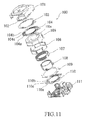
- FIG.11 is an exploded perspective view of an autofocus actuator assembly 100 used in a conventional camera module for displacing a lens unit (not shown) in a direction of an optical axis thereof. It is to be noted that an imaging element (not shown) is provided below a base 111 of the actuator assembly 100.
- a holder 108 that houses a barrel (not shown) holding the lens unit is provided between a cover 101 and the base 111 so that the holder 108 is displaceable in a direction of an optical axis of the lens unit together with the lens unit.
- An inner annular portion 104b of an upper leaf spring 104 and an inner annular portion 110b of a lower leaf spring 110 are attached to the upper and lower cylindrical portions of the holder 108, respectively. Further, an outer annular portion 104a of the upper leaf spring 104 is attached to an upper surface of a yoke 105 which is mounted on the base 111 and an outer annular portion 110a of the lower leaf spring 110 is attached to the base 111, respectively.
- Three bridge portions 104c are coupled between the outer annular portion 104a and the inner annular portion 104b of the upper leaf spring 104.
- three bridge portions 110c are coupled between the outer annular portion 110a and the inner annular portion 110b of the lower leaf spring 110.
- a plurality of magnet pieces 106 are bonded to the yoke 105 so as to produce a magnetic circuit.
- the yoke 105 has an axial bore 105a for receiving the holder 108.
- a coil 107 is provided around an outer periphery of the holder 108 so that the coil 7 is disposed in the magnetic field produced by the magnet pieces 106 and the yoke 105 in a state that the holder 108 is received in the axial bore 105a.
- a component denoted by the reference numeral 103 is a flexible printed circuit board used for supplying a current to the coli 107
- a component denoted by the reference numeral 102 is a stopper arranged above the upper surface of the inner annular portion 104a of the upper leaf spring 104
- a component donated by the reference numeral 109 is a plate provided between the lower leaf spring 110 and the bottom surface of the yoke 105.
- FIG. 12 is a top plan view of the lower leaf spring 110.
- the upper leaf spring 104 and the lower leaf spring 110 have the common basic structure excepting that the shapes of the outer annular portions 104a, 110a are different from each other. Therefore, in the following description, an explanation will be made only for the lower leaf spring 110, and an explanation for the upper leaf spring 104 is omitted.
- the lower leaf spring 110 includes a ring-shaped outer annular portion 110a, a ring-shaped inner annular portion 110b arranged inside the outer annular portion 110a through an annular spacing 110f and having the common axis with the outer annular portion 110a, and three bridge portions 110c coupled between the outer annular portion 110a and the inner annular portion 110b for supporting the inner annular portion 104b with respect to the outer annular portion 104a.
- Each of the bridge portions 104c has an elongated arc shape and provided in the ring-shaped spacing 110f so as to extend along the inner periphery of the outer annular portion 110a and the outer periphery of the inner annular portion 110b through a predetermined angle.
- the upper leaf spring 104 and the lower leaf spring 110 are formed from a thin metal plate made of beryllium copper.
- the thin metal plate is produced through a metal rolling process and it is then subjected to a punching process to form the leaf springs 104, 110.
- Such a beryllium copper plate has unevenness in its thickness along a direction through which the metal rolling process has been performed. Due to the unevenness of the thickness of the metal plate, there is a problem in that a load characteristic when it is used as the upper leaf spring 104 and the lower leaf spring 110 is not stable.
- a load characteristic of the leaf spring is affected by a heat treatment applied during the manufacturing process of the upper leaf spring 104 and the lower leaf spring 110, it is very difficult to obtain a leaf spring having a predetermined load characteristic.
- the plurality of magnet pieces 106 provided on the yoke 105 also have minute variations in their thickness. Due to such minute variations in their thickness, there is a case that a distance between each of the magnet pieces 106 and an outer surface of the coil 107 differs. In such a case, there is a problem in that it is not possible to ensure a stable driving force of the holder 108 within the magnetic circuit due to differences in magnetic forces applied to the coil 107.
- the present invention has been made in view of the problems described above, and therefore it is an object of the present invention is to provide a camera module which includes leaf springs having a stable load characteristic and a holder displaceably held by the leaf springs so that the holder can be stably displaced within a magnetic circuit.
- the present invention is directed to a camera module, which comprises: a lens unit which constitutes an optical system of the camera module; a holder which houses the lens unit and is displaceable along an optical axis direction of the lens unit; a coil provided on the holder; a yoke and magnets provided on the yoke for providing a magnetic field to the coil; at least one leaf spring for supporting the holder, the leaf spring including an outer annular portion, an inner annular portion provided inside the outer annular portion so as to be displaceable with respect to the outer annular portion and attached to the holder, and a plurality of bridge portions coupled between the outer annular portion and the inner annular portion; an imaging element provided below the lens unit; and bridge portion supporting means for supporting a part of each of the plurality of bridge portions so that a load characteristic of the leaf spring can be changed.
- the camera module of the present invention is provided with the bridge portion supporting means which can change a load characteristic of the leaf spring by supporting a selected region of each of the bridge portions of the leaf spring. Therefore, even in the case where a load characteristic of the leaf spring is not identical to a predetermined load characteristic due to unevenness in the thickness of a metal plate from which the leaf spring is formed and/or undesirable affect from a heat treatment or even in the case where there are minute variations in the thickness of each of the magnet pieces, it is possible to apparently adjust the spring constant of the leaf spring by using the bridge portion supporting means to thereby make it possible for the leaf spring to have the predetermined load characteristic, and as a result thereof it is possible to ensure a stable driving force of the holder in the magnetic circuit.
- the bridge portion supporting means of the camera module of the present invention is configured so as to support a selected region of the bridge portion of the leaf spring, it is also possible to make the leaf spring have the predetermined load characteristic by adjusting the effective deformable length of the bridge portion. This also makes it possible to ensure a stable driving force of the holder in the magnetic circuit.
- the bridge portion supporting means includes a ring-shaped annular portion and supporting portions which protrude inside the annular portion so as to support the bridge portions, and the bridge portion supporting means rotatably and concentrically provided with respect to the leaf spring so that the load characteristic of the leaf spring can be changed.
- the supporting parts of the bridge portion supporting means are formed so as to have resiliency.
- each of the supporting parts of the bridge portion supporting means has an extending part which extends from each supporting part along the extending direction of the bridge portion of the leaf spring.
- the bridge portion supporting means serves as a magnetic flux blocking member which blocks leakage of magnetic flux from the yoke.
- the leaf spring is rotatably supported on the bridge portion supporting means.
- the camera module includes a lens unit (not shown in the drawings) which constitutes an optical system of the camera module; a holder 9 which houses the lens unit and is displaceable along an optical axis direction of the lens unit; a coil 8 provided on the holder 9; a yoke 6 and a plurality of magnets 7 provided on the yoke 6 for providing a magnetic field to the coil 8; an upper leaf spring 5 for supporting the holder 9, the leaf spring 5 including an outer annular portion5a, an inner annular portion 5b provided inside the outer annular portion 5a so as to be displaceable with respect to the outer annular portion 5a and attached to the holder 8, and a plurality of bridge portions 5c coupled between the outer annular portion 5a and the inner annular portion 5b; and an imaging element (not shown in the drawing) provided below the lens unit; wherein the camera module is characterized by further providing a bridge portion supporting member 4 which serves as bridge portion supporting means for supporting a part of at least one of the plurality of bridge portions 5c
- an actuator assembly 1 of the camera module according to the embodiment of the present invention will be described in detail with reference to FIG. 1.
- the imaging element (not shown) is provided below a base 13.
- the holder 9 that houses the barrel (not shown) holding the lens unit is provided in a space defined between a cover 2 and the base 13 so that the holder 9 is displaceable in a direction of an optical axis of the lens unit.
- the inner annular portion 5b of the upper leaf spring 5 is attached to the upper end surface of a cylindrical portion of the holder 9.
- the inner annular portion lib of the lower leaf spring 11 is attached to the lower end surface of the cylindrical portion of the holder 9.
- the outer annular portion 5a (see FIG. 2) of the upper leaf spring 5 is attached to the upper surface of the yoke 5 and the outer annular portion 11a (see FIG. 8) of the lower leaf spring 11 is attached to the base 10.
- the bridge portion supporting member 4 includes a ring-shaped annular portion 4a having four outer periphery supporting parts 4d at four locations of the outer periphery of the ring-shaped annular portion 4a.
- the bridge portion supporting member 4 is rotatably supported on the base 13 with a state that the outer periphery supporting parts 4d are in slidable contact with four posts 13a of the base 13 (see FIG. 6).
- the bridge portion supporting member 11 also has a ring-shaped annular portion 10a (see FIG. 7) which is supported on the base 13.
- the plurality of magnet pieces 7 are bonded to the yoke 6 so as to produce a magnetic circuit of the actuator assembly 1. Further, the coil 8 is provided around an outer periphery of the holder 9 so that the coil 7 is disposed in the magnetic field generated by the magnet pieces 7 and the yoke 6.
- the yoke 6 has an axial bore 6a for receiving the holder 9. The holder 9 can be displaced through the axial bore Ga in a direction of an optical axis of the lens unit by supplying a current to the coil 8.
- a component denoted by the reference numeral 12 is a flexible printed circuit board used for supplying a current to the coil 8
- a component denoted by the reference numeral 2 is a stopper arranged above the upper surface of the inner annular portion 5b (see FIG. 2) of the upper leaf spring 5.
- the upper leaf spring 5 is formed from a thin metal plate made of beryllium copper through a punching process, and it has the ring-shaped outer annular portion 5a and the ring-shaped inner annular portion 5b which is concentrically provided inside the outer annular portion 5a through a predetermined annular spacing 5f.
- the inner annular portion 5b is supported by the outer annular portion 5a through the three bridge portions 5c.
- Each of the bridge portions 5c has an elongated arc-shape, and positioned inside the annular spacing 5f so that it extends along the inner periphery of the outer annular portion 5a and the outer periphery of the inner annular portion 5b through a predetermined angle.
- each of the bridge portions 5c has an outer annular portion side base part 5d.
- the bridge portion supporting member 4 is also formed from a thin metal plate made of beryllium copper through a punching process, and it has a ring-shaped annular portion 4a, three L-shaped supporting portions 4b which protrude from an inner periphery of the annular portion 4a so as to support the bridge portions 5c of the upper leaf spring 5, and four outer periphery supporting parts 4d at four locations of the outer periphery of the ring-shaped annular portion 4a. Further, a pair of operation pieces 4e are formed on the annular portion 4a so as to protrude outwardly.
- the bridge portion supporting member 4 is rotatably and concentrically provided with respect to the upper leaf spring 5. Specifically, although the upper leaf spring 5 is attached to the yoke 6 in a fixed state, the bridge portion supporting member 4 is rotatably supported on the base 13 with a state that the outer periphery supporting parts 4d are in slidable contact with the four posts 13a of the base 13 (see FIG. 6).
- Each of the supporting parts 4b of the bridge portion supporting member 4 has size and shape correspond to the outer annular portion side base part 5d of the bridge portion 5c of the upper leaf spring 5. Further, an extending part 4c which extends from the supporting part 4b along the extending direction of the bridge portion 5c of the leaf spring 5.
- FIGS. 4 and 5 are illustrations for explaining a state that the upper leaf spring 5 is combined with the bridge portion supporting member 4.
- the upper spring 5 is not rotatable, while only the bridge portion supporting member 4 is rotatable about the concentric axis with the upper spring 5.
- FIG. 4 shows a state that the bridge portion supporting member 4 has been rotated in an anticlockwise direction to a position where each extending part 4c of the supporting part 4b of the bridge portion supporting member 4 is overlapped with the outer annular portion side base part 5d of the corresponding bridge portion 5c of the upper leaf spring 5 by operating the operation pieces 4e with a predetermined gig.
- FIG. 5 shows a state that an area of the overlapping region of the extending part 4c and the bridge portion 5c becomes largest.
- the upper leaf spring 11 is formed from a thin metal plate made of beryllium copper through a punching process, and it has the outer annular portion 11a and the inner annular portion lib which is concentrically provided inside the outer annular portion 11a through a predetermined annular spacing 11f.
- the inner annular portion 11b is supported by the outer annular portion 11a through the three bridge portions 11c.
- Each of the bridge portions 11c has an arc-shape, and positioned inside the annular spacing 11f so that it extends along the inner peripheral edge of the outer annular portion 11a and the outer peripheral edge of the inner annular portion 11b through a predetermined angle.
- each of the bridge portions 11c has an outer annular portion side base part 11d.
- an operation piece 11e is formed on the annular portion 11a so as to protrude outwardly.
- the bridge portion supporting member 10 is rotatably and concentrically provided with respect to the lower leaf spring 11. Specifically, although the bridge portion supporting member 10 is attached to the base 13 in a fixed state, the lower leaf spring 11 is rotatably supported on the base 13 with a state that an outer periphery part is in slidable contact with an annular groove 13b of the base 13 (see FIG. 1).
- the bridge portion supporting member 10 is formed from a stainless steel plate which is easily magnetized and do not have any resiliency like a leaf spring for a camera module, and the bridge portion supporting member 10 is formed by subjecting such a stainless steel plate to a punching process.
- the bridge portion supporting member 10 has a ring-shaped annular portion 10a, three supporting portions 10b which protrude from an inner periphery of the annular portion 10a.
- Each of the supporting portions 10b has size and shape correspond to the outer annular portion side base part 11d of each of the bridge portions 11c.
- FIGS. 9 and 10 are illustrations for explaining a state that the lower leaf spring 11 is combined with the bridge portion supporting member 10.
- the bridge portion supporting member 10 is not rotatable, while only the lower leaf spring 11 is rotatable about the concentric axis with the bridge portion supporting member 10.
- FIG. 9 shows a state that the lower leaf spring 11 has been rotated in a clockwise direction to a position where only the outer annular portion side base part 11d of the bridge portion 11c of the lower leaf spring 11 is overlapped with the supporting portion 11b of the bridge portion supporting member 11 5 by operating the operation piece 11e with a predetermined gig.
- each supporting portion 10b supports only the base part 11c of the bridge portion 11c, a length of a portion of the bridge portion 11c which can be deformed (hereinafter, referred to as "effective deformable length") is longest.
- the lower leaf spring 11 is rotated in an anticlockwise direction so that the supporting portion 10b is overlapped with a portion of the bridge portion 11c over the outer annular portion side base part 11d, a region where the supporting portion 10b is overlapped with the bridge portion 11c (that is, a region indicated by "B" in FIG. 10) is gradually increased.
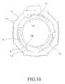
- FIG. 10 shows a state that an area of the overlapping region of the supporting part 10b and the bridge portion 11c becomes largest, and thus the effective deformable length of the bridge portion 11c is shortest.
- the camera module of this embodiment is provided with the bridge portion supporting member 4 which can change a load characteristic of the upper leaf spring 5 by supporting a selected region of each of the bridge portions 5c of the upper leaf spring 5. Therefore, even in the case where a load characteristic of the upper leaf spring is not identical to a predetermined load characteristic due to unevenness in the thickness of a metal plate from which the upper leaf spring 5 is formed and/or undesirable affect from a heat treatment or even in the case where there are minute variations in the thickness of each of the magnet pieces 7, it is possible to apparently adjust the spring constant of the upper leaf spring 5 by using the bridge portion supporting member 4 to thereby make it possible for the upper leaf spring 5 to have the predetermined load characteristic, and as a result thereof it is possible to ensure a stable driving force of the holder 9 in the magnetic circuit.
- the camera module of this embodiment is also provided with the bridge portion supporting member 10 which can support of a selected region of the bridge portion of the lower leaf spring 11, it is also possible to make the lower spring have the predetermined load characteristic by adjusting the effective deformable length of the bridge portion. This also makes it possible to ensure a stable driving force of the holder 9 in the magnetic circuit.
- the bridge portion supporting member 4 is rotatably and concentrically provided with respect to the upper leaf spring 5. Therefore, it is possible to adjust a load characteristic of the upper leaf spring 5 only by rotating the bridge portion supporting member 4.
- the supporting part 4b of the bridge portion supporting member 4 is formed to have resiliency. Therefore, by adding a spring constant of the supporting part 4b to a spring constant of the bridge portion 5c of the upper leaf spring 5, it is possible to apparently change a spring constant of the upper leaf spring 5.
- each of the supporting parts 4b of the bridge portion supporting member 4 has an extending part 4c which extends from each supporting part 4b along the extending direction of the bridge portion 5c of the upper leaf spring 5.
- the bridge portion supporting member 10 for the lower leaf spring 11 serves as a magnetic flux blocking member which blocks leakage of magnetic flux from the yoke 6. Therefore, since it is not necessary to provide an additional component for a magnetic flux blocking member, a number of necessary components can be reduced.
- the lower leaf spring 11 is rotatably supported on the bridge portion supporting member 10. This makes it possible for the bridge portion supporting member 10 to have other function such as the magnetic flux blocking member as described above.
- the present invention has been described based on the embodiment shown in the drawings having the upper and lower leaf springs and the bridge portions supporting members.
- the materials, shapes and sizes of the upper and lower leaf springs and the bridge portions supporting members are merely one example thereof, and they may be changed appropriately if necessary.
- the upper leaf spring and the bridge portion supporting member or the lower leaf spring and the bridge portion supporting member are configured so that they are relatively rotatable with respect to each other.
- it is sufficient if the upper leaf spring and the bridge portion supporting member or the lower leaf spring and the bridge portion supporting member are configured so that they can be relatively moved, namely, the relative rotational movement of the embodiment is not essential.
Landscapes
- Physics & Mathematics (AREA)
- General Physics & Mathematics (AREA)
- Optics & Photonics (AREA)
- Engineering & Computer Science (AREA)
- General Engineering & Computer Science (AREA)
- Lens Barrels (AREA)
- Studio Devices (AREA)
Abstract
Description
- This invention relates to a camera module, and more specifically to a camera module that can be used in small-sized electronic apparatuses such as digital cameras, camera-equipped cellular phones and the like.
- A camera module having a function of displacing a lens unit in a direction of an optical axis of the lens unit is used in relatively small-sized digital cameras and camera-equipped cellular phones and the like. This function is used for providing an autofocus function an/or zoom function and the like, and is achieved by an interaction between a magnetic field generated by an electrical current flowing in a coil and a magnetic field generated by a yoke and magnets provided on the yoke.
- Such a camera module includes a barrel which holds the lens unit, a holder which houses the barrel therein, and a pair of leaf springs for supporting the holder so that the holder is displaceable in a direction of an optical axis of the lens unit.
- FIG.11 is an exploded perspective view of an
autofocus actuator assembly 100 used in a conventional camera module for displacing a lens unit (not shown) in a direction of an optical axis thereof. It is to be noted that an imaging element (not shown) is provided below abase 111 of theactuator assembly 100. - A
holder 108 that houses a barrel (not shown) holding the lens unit is provided between acover 101 and thebase 111 so that theholder 108 is displaceable in a direction of an optical axis of the lens unit together with the lens unit. - An inner
annular portion 104b of anupper leaf spring 104 and an innerannular portion 110b of alower leaf spring 110 are attached to the upper and lower cylindrical portions of theholder 108, respectively. Further, an outerannular portion 104a of theupper leaf spring 104 is attached to an upper surface of ayoke 105 which is mounted on thebase 111 and an outerannular portion 110a of thelower leaf spring 110 is attached to thebase 111, respectively. - Three
bridge portions 104c are coupled between the outerannular portion 104a and the innerannular portion 104b of theupper leaf spring 104. As is the same with theupper leaf spring 104, threebridge portions 110c are coupled between the outerannular portion 110a and the innerannular portion 110b of thelower leaf spring 110. By resilient deformation of the respective threebridge portions holder 108 can be displaced in a direction of an optical axis of the lens unit. - A plurality of
magnet pieces 106 are bonded to theyoke 105 so as to produce a magnetic circuit. Theyoke 105 has anaxial bore 105a for receiving theholder 108. Further, acoil 107 is provided around an outer periphery of theholder 108 so that thecoil 7 is disposed in the magnetic field produced by themagnet pieces 106 and theyoke 105 in a state that theholder 108 is received in theaxial bore 105a. By supplying a current to thecoil 107 to generate a magnetic field, a driving force for displaying theholder 108 in a direction of an optical axis of the lens unit is generated. In this regard, it is to be noted that a component denoted by thereference numeral 103 is a flexible printed circuit board used for supplying a current to thecoli 107, a component denoted by thereference numeral 102 is a stopper arranged above the upper surface of the innerannular portion 104a of theupper leaf spring 104, and a component donated by thereference numeral 109 is a plate provided between thelower leaf spring 110 and the bottom surface of theyoke 105. - FIG. 12 is a top plan view of the
lower leaf spring 110. In this regard, it is to be noted that theupper leaf spring 104 and thelower leaf spring 110 have the common basic structure excepting that the shapes of the outerannular portions lower leaf spring 110, and an explanation for theupper leaf spring 104 is omitted. - As shown in Fig. 12, the
lower leaf spring 110 includes a ring-shaped outerannular portion 110a, a ring-shaped innerannular portion 110b arranged inside the outerannular portion 110a through an annular spacing 110f and having the common axis with the outerannular portion 110a, and threebridge portions 110c coupled between the outerannular portion 110a and the innerannular portion 110b for supporting the innerannular portion 104b with respect to the outerannular portion 104a. Each of thebridge portions 104c has an elongated arc shape and provided in the ring-shaped spacing 110f so as to extend along the inner periphery of the outerannular portion 110a and the outer periphery of the innerannular portion 110b through a predetermined angle. - In this regard, it is to be noted that an actuator assembly similar to the
actuator assembly 100 having suchupper leaf spring 104 andlower leaf spring 110 described above is disclosed inJP-A-No.2004-280031 - The
upper leaf spring 104 and thelower leaf spring 110 are formed from a thin metal plate made of beryllium copper. The thin metal plate is produced through a metal rolling process and it is then subjected to a punching process to form theleaf springs upper leaf spring 104 and thelower leaf spring 110 is not stable. When theleaf springs holder 108 when an electrical current is supplied to thecoil 107 are not stable, and thus it becomes difficult to precisely control the position of theholder 108. - Further, a load characteristic of the leaf spring is affected by a heat treatment applied during the manufacturing process of the
upper leaf spring 104 and thelower leaf spring 110, it is very difficult to obtain a leaf spring having a predetermined load characteristic. - Further, the plurality of
magnet pieces 106 provided on theyoke 105 also have minute variations in their thickness. Due to such minute variations in their thickness, there is a case that a distance between each of themagnet pieces 106 and an outer surface of thecoil 107 differs. In such a case, there is a problem in that it is not possible to ensure a stable driving force of theholder 108 within the magnetic circuit due to differences in magnetic forces applied to thecoil 107. - The present invention has been made in view of the problems described above, and therefore it is an object of the present invention is to provide a camera module which includes leaf springs having a stable load characteristic and a holder displaceably held by the leaf springs so that the holder can be stably displaced within a magnetic circuit.
- In order to achieve the object, the present invention is directed to a camera module, which comprises: a lens unit which constitutes an optical system of the camera module; a holder which houses the lens unit and is displaceable along an optical axis direction of the lens unit; a coil provided on the holder; a yoke and magnets provided on the yoke for providing a magnetic field to the coil; at least one leaf spring for supporting the holder, the leaf spring including an outer annular portion, an inner annular portion provided inside the outer annular portion so as to be displaceable with respect to the outer annular portion and attached to the holder, and a plurality of bridge portions coupled between the outer annular portion and the inner annular portion; an imaging element provided below the lens unit; and bridge portion supporting means for supporting a part of each of the plurality of bridge portions so that a load characteristic of the leaf spring can be changed.
- The camera module of the present invention is provided with the bridge portion supporting means which can change a load characteristic of the leaf spring by supporting a selected region of each of the bridge portions of the leaf spring. Therefore, even in the case where a load characteristic of the leaf spring is not identical to a predetermined load characteristic due to unevenness in the thickness of a metal plate from which the leaf spring is formed and/or undesirable affect from a heat treatment or even in the case where there are minute variations in the thickness of each of the magnet pieces, it is possible to apparently adjust the spring constant of the leaf spring by using the bridge portion supporting means to thereby make it possible for the leaf spring to have the predetermined load characteristic, and as a result thereof it is possible to ensure a stable driving force of the holder in the magnetic circuit. Further, since the bridge portion supporting means of the camera module of the present invention is configured so as to support a selected region of the bridge portion of the leaf spring, it is also possible to make the leaf spring have the predetermined load characteristic by adjusting the effective deformable length of the bridge portion. This also makes it possible to ensure a stable driving force of the holder in the magnetic circuit.
- In the camera module of the present invention, it is preferred that the bridge portion supporting means includes a ring-shaped annular portion and supporting portions which protrude inside the annular portion so as to support the bridge portions, and the bridge portion supporting means rotatably and concentrically provided with respect to the leaf spring so that the load characteristic of the leaf spring can be changed.
- With this structure, it is possible to adjust a load characteristic of the leaf spring only by rotating the bridge portion supporting means.
- Further, in the camera module of the present invention, it is also preferred that the supporting parts of the bridge portion supporting means are formed so as to have resiliency.
- With this structure, by adding a spring constant of the supporting part to a spring constant of the bridge portion of the leaf spring, it is possible to apparently change the spring constant of the leaf spring.
- Furthermore, in the camera module of the present invention, it is also preferred that each of the supporting parts of the bridge portion supporting means has an extending part which extends from each supporting part along the extending direction of the bridge portion of the leaf spring.
- With this structure, by appropriately selecting an extending length of the extending part, it is possible to easily adjust the resiliency of the supporting part.
- Furthermore, in the camera module of the present invention, it is also preferred that the bridge portion supporting means serves as a magnetic flux blocking member which blocks leakage of magnetic flux from the yoke.
- With this structure, since it is not necessary to provide an additional component for a magnetic flux blocking member, a number of necessary components can be reduced.
- Moreover, in the camera module of the present invention, it is also preferred that the leaf spring is rotatably supported on the bridge portion supporting means.
- With this structure, it possible for the bridge portion supporting means to have other function such as the magnetic flux blocking member as described above.
- The above and other objects, features and advantages of the present invention will be apparent from the following description when taken in conjunction with the accompanying drawings which illustrate preferred embodiments of the present invention by way of example.
-
- FIG. 1 is an explored perspective view of an
actuator assembly 1 of a camera module according to an embodiment of the present invention. - FIG. 2 is a top plan view of an
upper leaf spring 5 used in the camera module shown in FIG. 1. - FIG. 3 is a top plan view of a bridge
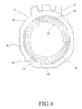
portion supporting member 4 of the camera module shown in FIG. 1. - FIG. 4 is an illustration for explaining a state that the bridge
portion supporting member 4 of the camera module shown in FIG. 1 is combined with theupper leaf spring 5. - FIG. 5 is an illustration for explaining another state that the bridge
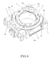
portion supporting member 4 of the camera module shown in FIG. 1 is combined with theupper leaf spring 5. - FIG. 6 is a perspective view which shows a state that the
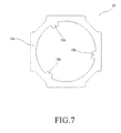
upper leaf spring 5 and the bridgeportion supporting member 4 of the camera module shown in FIG. 1 are assembled with abase 13. - FIG. 7 is a top plan view of the bridge
portion supporting member 10 of the camera module shown in FIG. 1. - FIG. 8 is a top plan view of a
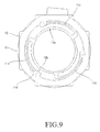
lower leaf spring 11 used in the camera module shown in FIG. 1. - FIG. 9 is an illustration for explaining a state that the bridge
portion supporting member 10 of the camera module shown in FIG. 1. is combined with thelower leaf spring 11. - FIG. 10 is an illustration for explaining another state that the bridge
portion supporting member 10 of the camera module shown in FIG. 1 is combined with thelower leaf spring 11. - FIG. 11 is an explored perspective view of an
actuator assembly 100 of the conventional camera module. - FIG. 12 is a top plan of a
lower leaf spring 110 used in theactuator assembly 100 of the conventional camera module. - A camera module according to an embodiment of the present invention will be described below with reference to the accompanying drawings.
- The camera module according to the embodiment includes a lens unit (not shown in the drawings) which constitutes an optical system of the camera module; a
holder 9 which houses the lens unit and is displaceable along an optical axis direction of the lens unit; acoil 8 provided on theholder 9; ayoke 6 and a plurality ofmagnets 7 provided on theyoke 6 for providing a magnetic field to thecoil 8; anupper leaf spring 5 for supporting theholder 9, theleaf spring 5 including an outer annular portion5a, an innerannular portion 5b provided inside the outerannular portion 5a so as to be displaceable with respect to the outerannular portion 5a and attached to theholder 8, and a plurality ofbridge portions 5c coupled between the outerannular portion 5a and the innerannular portion 5b; and an imaging element (not shown in the drawing) provided below the lens unit; wherein the camera module is characterized by further providing a bridgeportion supporting member 4 which serves as bridge portion supporting means for supporting a part of at least one of the plurality ofbridge portions 5c of theupper leaf spring 5 so that a load characteristic of theupper leaf spring 5 can be changed. Note that alower leaf spring 10 and a bridgeportion supporting member 11 described later also have this feature. - Hereinbelow, an
actuator assembly 1 of the camera module according to the embodiment of the present invention will be described in detail with reference to FIG. 1. In this regard, it is to be noted that the imaging element (not shown) is provided below abase 13. - The
holder 9 that houses the barrel (not shown) holding the lens unit is provided in a space defined between acover 2 and the base 13 so that theholder 9 is displaceable in a direction of an optical axis of the lens unit. - The inner
annular portion 5b of theupper leaf spring 5 is attached to the upper end surface of a cylindrical portion of theholder 9. In the same way, the inner annular portion lib of thelower leaf spring 11 is attached to the lower end surface of the cylindrical portion of theholder 9. The outerannular portion 5a (see FIG. 2) of theupper leaf spring 5 is attached to the upper surface of theyoke 5 and the outerannular portion 11a (see FIG. 8) of thelower leaf spring 11 is attached to thebase 10. - Between the
upper leaf spring 5 and thecover 3, there is provided a bridgeportion supporting member 4 which will be described later. As shown in FIG. 3, the bridgeportion supporting member 4 includes a ring-shapedannular portion 4a having four outerperiphery supporting parts 4d at four locations of the outer periphery of the ring-shapedannular portion 4a. The bridgeportion supporting member 4 is rotatably supported on the base 13 with a state that the outerperiphery supporting parts 4d are in slidable contact with fourposts 13a of the base 13 (see FIG. 6). - Further, between the
lower leaf spring 11 and theyoke 6, there is provided a bridgeportion supporting member 11 which will be described later. The bridgeportion supporting member 11 also has a ring-shapedannular portion 10a (see FIG. 7) which is supported on thebase 13. - The plurality of
magnet pieces 7 are bonded to theyoke 6 so as to produce a magnetic circuit of theactuator assembly 1. Further, thecoil 8 is provided around an outer periphery of theholder 9 so that thecoil 7 is disposed in the magnetic field generated by themagnet pieces 7 and theyoke 6. Theyoke 6 has anaxial bore 6a for receiving theholder 9. Theholder 9 can be displaced through the axial bore Ga in a direction of an optical axis of the lens unit by supplying a current to thecoil 8. It is noted that a component denoted by thereference numeral 12 is a flexible printed circuit board used for supplying a current to thecoil 8, and a component denoted by thereference numeral 2 is a stopper arranged above the upper surface of the innerannular portion 5b (see FIG. 2) of theupper leaf spring 5. - Hereinbelow, referring to FIG. 2 to FIG. 6 a description will be made with regard to the
upper leaf spring 5 and the bridgeportion supporting member 4. - As shown in FIG.2, the
upper leaf spring 5 is formed from a thin metal plate made of beryllium copper through a punching process, and it has the ring-shaped outerannular portion 5a and the ring-shaped innerannular portion 5b which is concentrically provided inside the outerannular portion 5a through a predeterminedannular spacing 5f. The innerannular portion 5b is supported by the outerannular portion 5a through the threebridge portions 5c. Each of thebridge portions 5c has an elongated arc-shape, and positioned inside theannular spacing 5f so that it extends along the inner periphery of the outerannular portion 5a and the outer periphery of the innerannular portion 5b through a predetermined angle. Further, each of thebridge portions 5c has an outer annular portionside base part 5d. - As shown in FIG. 3, the bridge
portion supporting member 4 is also formed from a thin metal plate made of beryllium copper through a punching process, and it has a ring-shapedannular portion 4a, three L-shaped supportingportions 4b which protrude from an inner periphery of theannular portion 4a so as to support thebridge portions 5c of theupper leaf spring 5, and four outerperiphery supporting parts 4d at four locations of the outer periphery of the ring-shapedannular portion 4a. Further, a pair ofoperation pieces 4e are formed on theannular portion 4a so as to protrude outwardly. - The bridge
portion supporting member 4 is rotatably and concentrically provided with respect to theupper leaf spring 5. Specifically, although theupper leaf spring 5 is attached to theyoke 6 in a fixed state, the bridgeportion supporting member 4 is rotatably supported on the base 13 with a state that the outerperiphery supporting parts 4d are in slidable contact with the fourposts 13a of the base 13 (see FIG. 6). - Each of the supporting
parts 4b of the bridgeportion supporting member 4 has size and shape correspond to the outer annular portionside base part 5d of thebridge portion 5c of theupper leaf spring 5. Further, an extendingpart 4c which extends from the supportingpart 4b along the extending direction of thebridge portion 5c of theleaf spring 5. - Each of FIGS. 4 and 5 is an illustration for explaining a state that the
upper leaf spring 5 is combined with the bridgeportion supporting member 4. As shown in FIGS. 4 and 5, theupper spring 5 is not rotatable, while only the bridgeportion supporting member 4 is rotatable about the concentric axis with theupper spring 5. FIG. 4 shows a state that the bridgeportion supporting member 4 has been rotated in an anticlockwise direction to a position where each extendingpart 4c of the supportingpart 4b of the bridgeportion supporting member 4 is overlapped with the outer annular portionside base part 5d of the correspondingbridge portion 5c of theupper leaf spring 5 by operating theoperation pieces 4e with a predetermined gig. In this state, since the extendingpart 4c supports only thebase part 5c of thebridge portion 5c, thebridge portion 5c is in a state of being easily deformable. On the other hand, as the bridgeportion supporting member 4 is rotated in a clockwise direction so that the extendingpart 4c is overlapped with a portion of thebridge portion 5c over the outer annular portionside base part 5d, a region where the extendingpart 4c is overlapped with thebridge portion 5c (that is, a region indicated by "A" in FIG. 5) is gradually increased. FIG. 5 shows a state that an area of the overlapping region of the extendingpart 4c and thebridge portion 5c becomes largest. - Next, description will be made with regard to an adjustment operation of a spring constant of the
upper leaf spring 5 in assembling the camera module according to this embodiment. - As described above, by rotating the bridge
portion supporting member 4 with respect to theupper leaf spring 5, it is possible to change the area of the overlapping region of the extendingpart 4c and thebridge portion 5c. As the area increases, a spring constant of the extendingpart 4c is added to the spring constant of thebridge portion 5c according to the increasing of the area. Therefore, though the spring constant of the upper leaf spring being unchanged, the spring constant of theupper leaf spring 5 is apparently increased due to the addition of the spring constant of the extendingpart 4c. As a result, it is possible to adjust a load characteristic of theupper leaf spring 5. In this regard, it is to be noted that after completion of the adjustment operation described above, the bridgeportion supporting member 4 is fixed in thebase 13 by bonding a part of the bridgeportion supporting member 4 to thebase 13. - Hereinbelow, referring to FIG. 7 to FIG. 10 description will be made with regard to the
lower leaf spring 11 and the bridgeportion supporting member 10. - As shown in FIG.8, the
upper leaf spring 11 is formed from a thin metal plate made of beryllium copper through a punching process, and it has the outerannular portion 11a and the inner annular portion lib which is concentrically provided inside the outerannular portion 11a through a predeterminedannular spacing 11f. The innerannular portion 11b is supported by the outerannular portion 11a through the threebridge portions 11c. Each of thebridge portions 11c has an arc-shape, and positioned inside theannular spacing 11f so that it extends along the inner peripheral edge of the outerannular portion 11a and the outer peripheral edge of the innerannular portion 11b through a predetermined angle. Further, each of thebridge portions 11c has an outer annular portionside base part 11d. Furthermore, anoperation piece 11e is formed on theannular portion 11a so as to protrude outwardly. - The bridge
portion supporting member 10 is rotatably and concentrically provided with respect to thelower leaf spring 11. Specifically, although the bridgeportion supporting member 10 is attached to the base 13 in a fixed state, thelower leaf spring 11 is rotatably supported on the base 13 with a state that an outer periphery part is in slidable contact with anannular groove 13b of the base 13 (see FIG. 1). - As shown in FIG. 7, the bridge
portion supporting member 10 is formed from a stainless steel plate which is easily magnetized and do not have any resiliency like a leaf spring for a camera module, and the bridgeportion supporting member 10 is formed by subjecting such a stainless steel plate to a punching process. The bridgeportion supporting member 10 has a ring-shapedannular portion 10a, three supportingportions 10b which protrude from an inner periphery of theannular portion 10a. Each of the supportingportions 10b has size and shape correspond to the outer annular portionside base part 11d of each of thebridge portions 11c. - Each of FIGS. 9 and 10 is an illustration for explaining a state that the
lower leaf spring 11 is combined with the bridgeportion supporting member 10. As shown in FIGS. 9 and 10, the bridgeportion supporting member 10 is not rotatable, while only thelower leaf spring 11 is rotatable about the concentric axis with the bridgeportion supporting member 10. FIG. 9 shows a state that thelower leaf spring 11 has been rotated in a clockwise direction to a position where only the outer annular portionside base part 11d of thebridge portion 11c of thelower leaf spring 11 is overlapped with the supportingportion 11b of the bridgeportion supporting member 11 5 by operating theoperation piece 11e with a predetermined gig. In this state, since each supportingportion 10b supports only thebase part 11c of thebridge portion 11c, a length of a portion of thebridge portion 11c which can be deformed (hereinafter, referred to as "effective deformable length") is longest. On the other hand, as thelower leaf spring 11 is rotated in an anticlockwise direction so that the supportingportion 10b is overlapped with a portion of thebridge portion 11c over the outer annular portionside base part 11d, a region where the supportingportion 10b is overlapped with thebridge portion 11c (that is, a region indicated by "B" in FIG. 10) is gradually increased. FIG. 10 shows a state that an area of the overlapping region of the supportingpart 10b and thebridge portion 11c becomes largest, and thus the effective deformable length of thebridge portion 11c is shortest. - Next, description will be made with regard to an adjustment operation of a spring constant of the
lower leaf spring 10 in assembling the camera module according to this embodiment. - As described above, by rotating the
lower leaf spring 11 with respect to the bridgeportion supporting member 10, it is possible to change the area of the overlapping region of the supportingportion 10b and thebridge portion 11a : As the area increases, a length of the effective deformable length of thebridge portion 11c becomes shorter according to the increasing of the area. Therefore, though the length of thebridge portion 11c of thelower leaf spring 11 being unchanged, the effective deformable length of thebridge portion 11c of thelower leaf spring 11 is apparently decreased due to the decreasing of the effective deformable length of thebridge portion 11c . As a result, it is possible to adjust a load characteristic of thelower leaf spring 11. In this regard, it is to be noted that after completion of the adjustment operation described above, thelower spring 11 is fixed to thebase 13 by bonding a part of thelower leaf spring 11 to thebase 13. - Hereinbelow, the operations and results of the embodiment will be described.
- The camera module of this embodiment is provided with the bridge
portion supporting member 4 which can change a load characteristic of theupper leaf spring 5 by supporting a selected region of each of thebridge portions 5c of theupper leaf spring 5. Therefore, even in the case where a load characteristic of the upper leaf spring is not identical to a predetermined load characteristic due to unevenness in the thickness of a metal plate from which theupper leaf spring 5 is formed and/or undesirable affect from a heat treatment or even in the case where there are minute variations in the thickness of each of themagnet pieces 7, it is possible to apparently adjust the spring constant of theupper leaf spring 5 by using the bridgeportion supporting member 4 to thereby make it possible for theupper leaf spring 5 to have the predetermined load characteristic, and as a result thereof it is possible to ensure a stable driving force of theholder 9 in the magnetic circuit. - Further, since the camera module of this embodiment is also provided with the bridge
portion supporting member 10 which can support of a selected region of the bridge portion of thelower leaf spring 11, it is also possible to make the lower spring have the predetermined load characteristic by adjusting the effective deformable length of the bridge portion. This also makes it possible to ensure a stable driving force of theholder 9 in the magnetic circuit. - Further, in the camera module of this embodiment, only the bridge
portion supporting member 4 is rotatably and concentrically provided with respect to theupper leaf spring 5. Therefore, it is possible to adjust a load characteristic of theupper leaf spring 5 only by rotating the bridgeportion supporting member 4. - Furthermore, in the camera module of this embodiment, the supporting
part 4b of the bridgeportion supporting member 4 is formed to have resiliency. Therefore, by adding a spring constant of the supportingpart 4b to a spring constant of thebridge portion 5c of theupper leaf spring 5, it is possible to apparently change a spring constant of theupper leaf spring 5. - Furthermore, in the camera module of this embodiment, each of the supporting
parts 4b of the bridgeportion supporting member 4 has an extendingpart 4c which extends from each supportingpart 4b along the extending direction of thebridge portion 5c of theupper leaf spring 5. By appropriately selecting an extending length of the extendingpart 4c, it is possible to easily adjust the resiliency of the supportingpart 4b. - Furthermore, in the camera module of this embodiment, the bridge
portion supporting member 10 for thelower leaf spring 11 serves as a magnetic flux blocking member which blocks leakage of magnetic flux from theyoke 6. Therefore, since it is not necessary to provide an additional component for a magnetic flux blocking member, a number of necessary components can be reduced. - Moreover, in the camera module of this embodiment, the
lower leaf spring 11 is rotatably supported on the bridgeportion supporting member 10. This makes it possible for the bridgeportion supporting member 10 to have other function such as the magnetic flux blocking member as described above. - In the foregoings, the present invention has been described based on the embodiment shown in the drawings having the upper and lower leaf springs and the bridge portions supporting members. However, the materials, shapes and sizes of the upper and lower leaf springs and the bridge portions supporting members are merely one example thereof, and they may be changed appropriately if necessary. Further, in the embodiment described above, the upper leaf spring and the bridge portion supporting member or the lower leaf spring and the bridge portion supporting member are configured so that they are relatively rotatable with respect to each other. However, in the present invention, it is sufficient if the upper leaf spring and the bridge portion supporting member or the lower leaf spring and the bridge portion supporting member are configured so that they can be relatively moved, namely, the relative rotational movement of the embodiment is not essential.
- Finally, it should be understood that the present invention is not limited to the preferred embodiments described hereinabove and, needless to say, a variety of modifications or variations may be made without departing from the scope of the invention defined in the following claims.
- Further, it is also to be understood that the present disclosure relates to subject matter contained in
Japanese Patent Application No. 2006-236884 (filed on August 31, 2006
Claims (6)
- A camera module, comprising:a lens unit which constitutes an optical system of the camera module;a holder which houses the lens unit and is displaceable along an optical axis direction of the lens unit;a coil provided on the holder;a yoke and magnets provided on the yoke for providing a magnetic field to the coil;at least one leaf spring for supporting the holder, the leaf spring including an outer annular portion, an inner annular portion provided inside the outer annular portion so as to be displaceable with respect to the outer annular portion and attached to the holder, and a plurality of bridge portions coupled between the outer annular portion and the inner annular portion;an imaging element provided below the lens unit, andbridge portion supporting means for supporting a part of each of the plurality of bridge portions so that a load characteristic of the leaf spring can be changed.
- The camera module as claimed in claim 1, wherein the bridge portion supporting means includes a ring-shaped annular portion and supporting portions which protrude inside the annular portion so as to support the bridge portions of the leaf spring, and the bridge portion supporting means rotatably and concentrically provided with respect to the leaf spring so that the load characteristic of the leaf spring can be changed.
- The camera module as claimed in claim 1, wherein the supporting parts of the bridge portion supporting means are formed so as to have resiliency.
- The camera module as claimed in claim 1, wherein each of the supporting parts of the bridge portion supporting means has an extending part which extends from each supporting part along the extending direction of the bridge portion of the leaf spring.
- The camera module as claimed in claim 2, wherein the bridge portion supporting means serves as a magnetic flux blocking member which blocks leakage of magnetic flux from the yoke.
- The camera module as claimed in claim 1, wherein the leaf spring is rotatably supported on the bridge portion supporting means.
Applications Claiming Priority (1)
| Application Number | Priority Date | Filing Date | Title |
|---|---|---|---|
| JP2006236884A JP4952149B2 (en) | 2006-08-31 | 2006-08-31 | The camera module |
Publications (2)
| Publication Number | Publication Date |
|---|---|
| EP1895343A1 true EP1895343A1 (en) | 2008-03-05 |
| EP1895343B1 EP1895343B1 (en) | 2009-12-23 |
Family
ID=38626917
Family Applications (1)
| Application Number | Title | Priority Date | Filing Date |
|---|---|---|---|
| EP07115201A Expired - Fee Related EP1895343B1 (en) | 2006-08-31 | 2007-08-29 | Camera module |
Country Status (4)
| Country | Link |
|---|---|
| US (1) | US7639440B2 (en) |
| EP (1) | EP1895343B1 (en) |
| JP (1) | JP4952149B2 (en) |
| DE (1) | DE602007003915D1 (en) |
Cited By (2)
| Publication number | Priority date | Publication date | Assignee | Title |
|---|---|---|---|---|
| USRE44371E1 (en) | 2007-02-02 | 2013-07-16 | Mitsumi Electric Co., Ltd. | Camera module |
| EP3525026A1 (en) * | 2018-02-09 | 2019-08-14 | Sick AG | Opto-electronic sensor and focus displacement method |
Families Citing this family (16)
| Publication number | Priority date | Publication date | Assignee | Title |
|---|---|---|---|---|
| TWM320097U (en) * | 2007-02-13 | 2007-10-01 | Mustek Systems Inc | High stability planar spring utilized in a voice coil motor |
| JP2009265210A (en) * | 2008-04-23 | 2009-11-12 | Shicoh Engineering Co Ltd | Lens drive unit, camera, and cellular phone with camera |
| JP2009282090A (en) * | 2008-05-20 | 2009-12-03 | Mitsumi Electric Co Ltd | Lens driving device |
| JP4706935B2 (en) | 2008-06-20 | 2011-06-22 | ソニー株式会社 | The camera module |
| JP5181208B2 (en) * | 2008-12-01 | 2013-04-10 | セイコーインスツル株式会社 | Drive module and electronic device |
| CN101750708A (en) * | 2008-12-12 | 2010-06-23 | 日本电产三协株式会社 | Lens driving device |
| JP2010151007A (en) * | 2008-12-25 | 2010-07-08 | Seiko Instruments Inc | Driving module and electronic device |
| JP5698939B2 (en) * | 2010-09-07 | 2015-04-08 | 日本電産サンキョー株式会社 | Optical unit with shake correction function |
| JP2012234136A (en) * | 2011-04-28 | 2012-11-29 | Shicoh Engineering Co Ltd | Lens drive device, autofocus camera, and portable terminal device |
| JP5329629B2 (en) * | 2011-09-26 | 2013-10-30 | シャープ株式会社 | The camera module |
| JP2014035467A (en) * | 2012-08-09 | 2014-02-24 | Dainippon Printing Co Ltd | Manufacturing method of leaf spring, drive mechanism of leaf spring and camera module |
| USRE48479E1 (en) | 2013-10-28 | 2021-03-23 | Happy Products, Inc. | Multiple viewing angle media support |
| TWI713733B (en) * | 2017-04-27 | 2020-12-21 | 揚明光學股份有限公司 | Lens adjusting mechanism |
| US11531182B2 (en) * | 2018-10-05 | 2022-12-20 | Tdk Taiwan Corp. | Optical element driving mechanism |
| CN211123432U (en) * | 2018-10-05 | 2020-07-28 | 台湾东电化股份有限公司 | Optical assembly drive mechanism |
| CN112333353B (en) * | 2019-08-02 | 2025-10-17 | 台湾东电化股份有限公司 | Optical element driving mechanism |
Citations (6)
| Publication number | Priority date | Publication date | Assignee | Title |
|---|---|---|---|---|
| US4601539A (en) * | 1983-05-07 | 1986-07-22 | Canon Kabushiki Kaisha | Lens moving device using piezoelectric material |
| US4634221A (en) * | 1983-11-05 | 1987-01-06 | Eastman Kodak Company | Focusing mechanism |
| US5289318A (en) * | 1990-07-31 | 1994-02-22 | Canon Kabushiki Kaisha | Optical apparatus provided with a driving unit for moving a lens |
| JP2004280031A (en) * | 2003-03-13 | 2004-10-07 | Shicoh Eng Co Ltd | Lens driving device |
| WO2005088153A1 (en) * | 2004-03-15 | 2005-09-22 | Sharp Kabushiki Kaisha | Plate spring and lens actuator having the same |
| US20060028320A1 (en) * | 2004-08-09 | 2006-02-09 | Mitsumi Electric Co., Ltd. | Autofocus actuator |
Family Cites Families (7)
| Publication number | Priority date | Publication date | Assignee | Title |
|---|---|---|---|---|
| JPS57117133A (en) * | 1981-01-09 | 1982-07-21 | Olympus Optical Co Ltd | Objective lens drive device |
| US4472024A (en) * | 1981-01-07 | 1984-09-18 | Olympus Optical Co. Ltd. | Apparatus for driving objective lens |
| JPS57113431A (en) * | 1981-01-07 | 1982-07-14 | Olympus Optical Co Ltd | Objective-lens driver |
| US5228017A (en) * | 1989-07-28 | 1993-07-13 | Victor Company Of Japan, Ltd. | Optical system drive apparatus for an optical recording/reproducing apparatus |
| US5519677A (en) * | 1993-03-22 | 1996-05-21 | Sony Corporation | Biaxial actuator for driving an objective lens in both focusing and tracking directions |
| JP3356918B2 (en) * | 1995-08-01 | 2002-12-16 | オリンパス光学工業株式会社 | Optical pickup |
| JP3606711B2 (en) * | 1997-07-07 | 2005-01-05 | 株式会社リコー | Optical head |
-
2006
- 2006-08-31 JP JP2006236884A patent/JP4952149B2/en not_active Expired - Fee Related
-
2007
- 2007-08-28 US US11/846,442 patent/US7639440B2/en active Active
- 2007-08-29 DE DE602007003915T patent/DE602007003915D1/en active Active
- 2007-08-29 EP EP07115201A patent/EP1895343B1/en not_active Expired - Fee Related
Patent Citations (6)
| Publication number | Priority date | Publication date | Assignee | Title |
|---|---|---|---|---|
| US4601539A (en) * | 1983-05-07 | 1986-07-22 | Canon Kabushiki Kaisha | Lens moving device using piezoelectric material |
| US4634221A (en) * | 1983-11-05 | 1987-01-06 | Eastman Kodak Company | Focusing mechanism |
| US5289318A (en) * | 1990-07-31 | 1994-02-22 | Canon Kabushiki Kaisha | Optical apparatus provided with a driving unit for moving a lens |
| JP2004280031A (en) * | 2003-03-13 | 2004-10-07 | Shicoh Eng Co Ltd | Lens driving device |
| WO2005088153A1 (en) * | 2004-03-15 | 2005-09-22 | Sharp Kabushiki Kaisha | Plate spring and lens actuator having the same |
| US20060028320A1 (en) * | 2004-08-09 | 2006-02-09 | Mitsumi Electric Co., Ltd. | Autofocus actuator |
Cited By (6)
| Publication number | Priority date | Publication date | Assignee | Title |
|---|---|---|---|---|
| USRE44371E1 (en) | 2007-02-02 | 2013-07-16 | Mitsumi Electric Co., Ltd. | Camera module |
| EP3525026A1 (en) * | 2018-02-09 | 2019-08-14 | Sick AG | Opto-electronic sensor and focus displacement method |
| CN110135214A (en) * | 2018-02-09 | 2019-08-16 | 西克股份公司 | Photoelectric sensor and method for focus adjustment |
| KR20190096803A (en) * | 2018-02-09 | 2019-08-20 | 식아게 | Optoelectronic sensor and method for adjusting focus |
| US11294139B2 (en) | 2018-02-09 | 2022-04-05 | Sick Ag | Optoelectronic sensor and method of focus adjustment |
| CN110135214B (en) * | 2018-02-09 | 2022-11-29 | 西克股份公司 | Photosensor and method for focus adjustment |
Also Published As
| Publication number | Publication date |
|---|---|
| US7639440B2 (en) | 2009-12-29 |
| JP4952149B2 (en) | 2012-06-13 |
| EP1895343B1 (en) | 2009-12-23 |
| US20080266682A1 (en) | 2008-10-30 |
| DE602007003915D1 (en) | 2010-02-04 |
| JP2008058733A (en) | 2008-03-13 |
Similar Documents
| Publication | Publication Date | Title |
|---|---|---|
| EP1895343B1 (en) | Camera module | |
| EP1895344B1 (en) | Camera module | |
| US8503119B2 (en) | Leaf spring with high vickers hardness | |
| US10690998B2 (en) | Camera module | |
| US8531789B2 (en) | Leaf spring with high thrust | |
| CN104898347B (en) | Camera lens module | |
| EP1906395A1 (en) | Camera module | |
| CN104797976B (en) | Optical devices for shooting | |
| EP1901103B1 (en) | Camera module | |
| EP1918749B1 (en) | Camera Module | |
| EP1998201A1 (en) | Lens barrel and imaging device | |
| US20190377239A1 (en) | Iris module and camera module including the same | |
| KR20060092067A (en) | Lens unit and imaging device | |
| KR20100131778A (en) | Lens Actuator for Imaging Device with Stable Focusing | |
| JP5341617B2 (en) | Lens drive device | |
| JP2023105217A (en) | rotary drive | |
| JP2010068635A (en) | Actuator, image pickup apparatus having same, and electronic device | |
| KR20160120578A (en) | Lens driving device | |
| EP1851808B1 (en) | Piezoelectric actuator element for micromovement | |
| JP4719107B2 (en) | Lens drive device | |
| JP2009150922A (en) | Actuators, imaging devices and portable electronic devices | |
| JP4262769B1 (en) | Actuator, imaging device, and electronic device | |
| KR100620790B1 (en) | Camera auto focus | |
| JP6278664B2 (en) | Lens drive device | |
| KR100560051B1 (en) | Bottom cover for camera auto focus |
Legal Events
| Date | Code | Title | Description |
|---|---|---|---|
| PUAI | Public reference made under article 153(3) epc to a published international application that has entered the european phase |
Free format text: ORIGINAL CODE: 0009012 |
|
| AK | Designated contracting states |
Kind code of ref document: A1 Designated state(s): AT BE BG CH CY CZ DE DK EE ES FI FR GB GR HU IE IS IT LI LT LU LV MC MT NL PL PT RO SE SI SK TR |
|
| AX | Request for extension of the european patent |
Extension state: AL BA HR MK YU |
|
| 17P | Request for examination filed |
Effective date: 20080905 |
|
| AKX | Designation fees paid |
Designated state(s): DE |
|
| RIC1 | Information provided on ipc code assigned before grant |
Ipc: G02B 7/10 20060101ALI20090513BHEP Ipc: G03B 13/34 20060101ALI20090513BHEP Ipc: G02B 7/08 20060101AFI20090513BHEP |
|
| RIN1 | Information on inventor provided before grant (corrected) |
Inventor name: OSAKA, TOMOHIKOMITSUMI ELECTRIC CO., LTD Inventor name: ISHIZAWA, TAKASHIMITSUMI ELECTRIC CO., LTD |
|
| GRAP | Despatch of communication of intention to grant a patent |
Free format text: ORIGINAL CODE: EPIDOSNIGR1 |
|
| GRAS | Grant fee paid |
Free format text: ORIGINAL CODE: EPIDOSNIGR3 |
|
| GRAA | (expected) grant |
Free format text: ORIGINAL CODE: 0009210 |
|
| AK | Designated contracting states |
Kind code of ref document: B1 Designated state(s): DE |
|
| REF | Corresponds to: |
Ref document number: 602007003915 Country of ref document: DE Date of ref document: 20100204 Kind code of ref document: P |
|
| PLBE | No opposition filed within time limit |
Free format text: ORIGINAL CODE: 0009261 |
|
| STAA | Information on the status of an ep patent application or granted ep patent |
Free format text: STATUS: NO OPPOSITION FILED WITHIN TIME LIMIT |
|
| PGFP | Annual fee paid to national office [announced via postgrant information from national office to epo] |
Ref country code: DE Payment date: 20100825 Year of fee payment: 4 |
|
| 26N | No opposition filed |
Effective date: 20100924 |
|
| REG | Reference to a national code |
Ref country code: DE Ref legal event code: R119 Ref document number: 602007003915 Country of ref document: DE Effective date: 20120301 |
|
| PG25 | Lapsed in a contracting state [announced via postgrant information from national office to epo] |
Ref country code: DE Free format text: LAPSE BECAUSE OF NON-PAYMENT OF DUE FEES Effective date: 20120301 |