EP1895153A1 - Starter-motor mounting structure for internal combustion engine - Google Patents
Starter-motor mounting structure for internal combustion engine Download PDFInfo
- Publication number
- EP1895153A1 EP1895153A1 EP07111300A EP07111300A EP1895153A1 EP 1895153 A1 EP1895153 A1 EP 1895153A1 EP 07111300 A EP07111300 A EP 07111300A EP 07111300 A EP07111300 A EP 07111300A EP 1895153 A1 EP1895153 A1 EP 1895153A1
- Authority
- EP
- European Patent Office
- Prior art keywords
- mounting boss
- transmission
- side mounting
- starter
- combustion engine
- Prior art date
- Legal status (The legal status is an assumption and is not a legal conclusion. Google has not performed a legal analysis and makes no representation as to the accuracy of the status listed.)
- Granted
Links
- 238000002485 combustion reaction Methods 0.000 title claims abstract description 43
- 230000005540 biological transmission Effects 0.000 claims abstract description 130
- 239000007858 starting material Substances 0.000 claims abstract description 41
- 238000005192 partition Methods 0.000 claims description 9
- 239000010687 lubricating oil Substances 0.000 description 18
- 230000001050 lubricating effect Effects 0.000 description 17
- 230000033001 locomotion Effects 0.000 description 3
- 238000005461 lubrication Methods 0.000 description 3
- 230000001133 acceleration Effects 0.000 description 2
- 239000003921 oil Substances 0.000 description 2
- 230000015572 biosynthetic process Effects 0.000 description 1
- 238000001816 cooling Methods 0.000 description 1
- 230000000694 effects Effects 0.000 description 1
- 230000002708 enhancing effect Effects 0.000 description 1
- 230000002093 peripheral effect Effects 0.000 description 1
- 238000000638 solvent extraction Methods 0.000 description 1
- 238000011144 upstream manufacturing Methods 0.000 description 1
Images



Classifications
-
- F—MECHANICAL ENGINEERING; LIGHTING; HEATING; WEAPONS; BLASTING
- F02—COMBUSTION ENGINES; HOT-GAS OR COMBUSTION-PRODUCT ENGINE PLANTS
- F02N—STARTING OF COMBUSTION ENGINES; STARTING AIDS FOR SUCH ENGINES, NOT OTHERWISE PROVIDED FOR
- F02N15/00—Other power-operated starting apparatus; Component parts, details, or accessories, not provided for in, or of interest apart from groups F02N5/00 - F02N13/00
-
- F—MECHANICAL ENGINEERING; LIGHTING; HEATING; WEAPONS; BLASTING
- F02—COMBUSTION ENGINES; HOT-GAS OR COMBUSTION-PRODUCT ENGINE PLANTS
- F02N—STARTING OF COMBUSTION ENGINES; STARTING AIDS FOR SUCH ENGINES, NOT OTHERWISE PROVIDED FOR
- F02N15/00—Other power-operated starting apparatus; Component parts, details, or accessories, not provided for in, or of interest apart from groups F02N5/00 - F02N13/00
- F02N15/006—Assembling or mounting of starting devices
-
- F—MECHANICAL ENGINEERING; LIGHTING; HEATING; WEAPONS; BLASTING
- F02—COMBUSTION ENGINES; HOT-GAS OR COMBUSTION-PRODUCT ENGINE PLANTS
- F02B—INTERNAL-COMBUSTION PISTON ENGINES; COMBUSTION ENGINES IN GENERAL
- F02B75/00—Other engines
- F02B75/16—Engines characterised by number of cylinders, e.g. single-cylinder engines
- F02B75/18—Multi-cylinder engines
- F02B75/22—Multi-cylinder engines with cylinders in V, fan, or star arrangement
Definitions
- the present invention relates to a structure for mounting a starter motor to a unit case of an internal combustion engine in which a crankcase and a transmission case are formed integrally.
- Examples of this kind of an internal combustion engine including a unit case according to the related art include the internal combustion engine for a motorcycle disclosed in Patent Document 1.
- the unit case of the internal combustion engine disclosed in Patent Document 1 in which a crankcase and a transmission case are formed integrally, is formed so as to be divided into upper and lower halves, and has a structure with a large front-to-rear width in which three shafts, including a crankshaft in a crank chamber and a main shaft and a counter shaft serving as transmission shafts in a transmission chamber, are journalled so as to be sandwiched between the horizontal parting surfaces of the unit case halves in the order of the crankshaft, the main shaft, and the counter shaft in the front-to-rear direction.
- a cylinder block projects from the front side portion of the crankcase while being tilted forward, and a pair of front and rear mounting bosses are bored in the rear-side portion of the upper wall.
- a starter motor is mounted by fastening support arms, which are provided so as to project in the front-to-rear direction of the starter motor, to the pair of front and rear mounting bosses.
- the unit case Since the crankshaft, the main shaft, and the counter shaft are disposed so as to be arranged side by side from front to rear in the horizontal parting surface of the unit case, the unit case has a large front-to-rear width. Accordingly, since it is not particularly necessary to raise the upper wall of the transmission case upward in order to accommodate gear groups on the main shaft and the counter shaft that are arranged side by side from front to rear in the transmission chamber, the space in rear of the cylinder block and above the upper wall of the unit case is large, and hence there is no need to take into consideration the interference between the starter motor mounted to the rear-side portion of the crankcase, and the upper wall of the transmission case.
- the present invention has been made in view of the above-mentioned problems, and accordingly it is an object of the present invention to provide a starter-motor mounting structure for an internal combustion engine which makes it possible to mount a starter motor to a unit case with high mounting rigidity while achieving a reduction in the size of an internal combustion engine.
- a starter-motor mounting structure for an internal combustion engine including a starter motor mounted on a unit case in which a crankcase for accommodating a crank mechanism and a transmission case for accommodating a transmission mechanism are integrally formed in a front-to-rear direction, wherein: a front-side mounting boss is formed in a rear-side inclined surface of a cylinder block that projects from the crankcase so as to be tilted forward; a rear-side mounting boss is formed in a front-side wall surface of a raised portion where an upper wall of the transmission case is raised upward so as to accommodate a main shaft that is positioned higher than a counter shaft of the transmission mechanism; the front-side mounting boss and the rear-side mounting boss are offset from each other in a crankshaft direction; and a front-side bracket and a rear-side bracket that extend from the starter motor are respectively fastened to the front-side mounting boss and the rear-side mounting boss.
- the front-side mounting boss is formed at a position that is offset from the a cylinder center axis in the crankshaft direction.
- a group of gears is accommodated in the raised portion of the upper wall of the transmission case, the group of gears including a plurality of gears of different diameters arranged on the main shaft inside the transmission case, and the rear-side mounting boss is formed at a position opposed to a small-diameter gear from among the group of gears.
- the rear-side mounting boss is formed in an upwardly extending portion of a partition wall that partitions between a crank chamber inside the crankcase and a transmission chamber inside the transmission case.
- the starter-motor mounting structure for an internal combustion engine in Claim 1
- the starter-motor mounting structure has the raised portion where the upper wall of the transmission case is raised upward so as to accommodate the main shaft that is positioned higher than the counter shaft, and the crankshaft, the main shaft, and the counter shaft are brought close to each other to achieve a reduction in the size of the internal combustion engine.
- the front-side mounting boss which is formed in the rear-side inclined surface of the cylinder block that projects from the crankcase so as to be tilted forward
- the rear-side mounting boss which is formed in the front-side wall surface of the raised portion where the upper wall of the transmission case is raised upward
- front-side bracket and the rear-side bracket that extend from the starter motor are fastened to the front-side mounting boss and the rear-side mounting boss that are thus arranged at a suitable spacing from each other, a high mounting rigidity is secured, and the influence of vibration acceleration exerted on the starter motor by the vibration of the internal combustion engine is reduced, thereby making it possible to enhance the durability of the starter motor.
- the front-side mounting boss is formed at a position that is offset from the cylinder center axis in the crankshaft direction. This means that the front-side mounting boss is formed at a location with the highest rigidity where a stud bolt or the like for fastening the cylinder head is arranged, thereby making it possible to enhance the rigidity of the front-side mounting boss itself. Further, the front-side mounting boss can be formed so as to be positioned further forward while avoiding the cylinder bore, that is, so as to be positioned as far forward as possible from the rear-side mounting boss, thereby making it possible to secure higher mounting rigidity by increasing the distance between the front-side mounting boss and the rear-side mounting boss.
- the rear-side mounting boss which is formed in the front-side wall surface of the raised portion of the upper portion of the transmission case accommodating a group of gears including a plurality of gears of different diameters arranged on the main shaft, is formed at a position opposed to a small-diameter gear from among the group of gears. Therefore, the rear-side mounting boss can be formed so as to be positioned further rearward in proximity to the small-diameter gear, that is, so as to be positioned as far rearward as possible from the front-side mounting boss, thereby making it possible to further increase the distance between the front-side mounting boss and the rear-side mounting boss to secure higher mounting rigidity.
- the rear-side mounting boss formed in the front-side wall surface of the raised portion of the transmission case is formed in the upwardly extending portion of the partition wall, which partitions between the crank chamber and the transmission chamber and represents a portion of the transmission case having a particularly high rigidity, thereby making it possible to enhance the rigidity of the rear-side mounting boss itself.
- An internal combustion engine E is a serial four-cylinder, water-cooling type four-stroke internal combustion engine in which four cylinders are arranged in series.
- the internal combustion engine E is horizontally mounted in a motorcycle with a crankshaft 10 oriented in the left-to-right direction.
- the advancing direction of the vehicle is defined as the front or forward
- the direction opposite to the advancing direction is defined as the rear or rearward
- the left-hand direction and the right-hand direction as seen facing the front or forward as the advancing direction are defined as the left or leftward and the right or rightward, respectively.
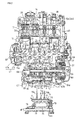
- FIG. 1 A left-side view of the internal combustion engine E is shown in Fig. 1.
- a transmission case 11m that forms a transmission chamber M for accommodating a transmission mechanism 60 are integrally formed in the front-to-rear direction to constitute a unit case 11.
- the unit case 11 itself is formed so as to be divided into an upper-side unit case 11U and a lower-side unit case 11L.
- a cylinder block portion 12 molded integrally from four serially arranged cylinder bores 12c is formed so as to extend upward while being tilted somewhat forward.
- a cylinder head 13 is laid on top of the cylinder block portion 12, and a cylinder head cover 14 is covered on top of the cylinder head 13.
- an oil sump 15 is mounted below the lower-side unit case 11L.
- a piston 30 is fitted in each of the cylinder bores 12c of the four cylinders of the cylinder block portion 12 so as to be capable of reciprocating sliding motion.
- the piston 30 is connected to the crankshaft 10 via a connecting rod 31.
- a combustion chamber 32 is formed so as to be opposed to the piston 30, an intake port 33, which is open to the combustion chamber 32 and opened and closed by a pair of intake valves 35, extends rearward, an exhaust port 34 opened and closed by a pair of exhaust valves 36 extends forward, and further, an ignition plug 37 facing the combustion chamber 32 is inserted.
- a throttle body 33a is connected to an upstream-side intake passage pipe 33b of the intake port 33 and, although not shown, an intake pipe is connected to the upstream side thereof, and an exhaust pipe is connected to a downstream-side opening of the exhaust port 34.
- Each of the intake valves 35 and each of the exhaust valves 36 are driven so as to open and close by an intake camshaft 38 and an exhaust camshaft 39, which are rotatably journalled to the cylinder head 13, in synchronism with the rotation of the crankshaft 10.
- cam sprockets 38s, 39s are fitted into the right end portions of the respective cam shafts 38, 39.
- a timing chain 40 is wound between a drive sprocket 10s, which is fitted into a portion near the right end portion of the crankshaft 10, and each of the cam sprockets 38s, 39s (see Fig. 2), and is rotationally driven at half the rotational speed of the crankshaft 10.
- crankshaft 10 is rotatably journalled while being sandwiched between the upper and lower crankcases 11eu, 11el via a main bearing 20.
- a starting driven gear 57 is journalled via a one-way clutch 58 to an end portion located on the further right side with respect to the driven sprocket 10s fitted as described above.
- an outer rotor 47r of an AC generator 47 is fitted into the left end portion of the crankshaft 10 extending through the left-side wall of the crankcase 11e.
- An inner stator 47s of the AC generator 47 which includes a generator coil is arranged inside the outer rotor 47r while being supported on a generator cover 48 that is covered to the AC generator 47 from the left.
- the transmission chamber M which is partitioned off by the crank chamber C of the crankcase 11e accommodating the crankshaft 10, and a partition wall 21, is formed on the rear side in the transmission case 11m (see Fig. 2 and Fig. 6).
- the transmission mechanism 60 accommodated in the transmission chamber M is a constant-mesh gear transmission.
- a main shaft 61 is rotatably journalled via bearings 62, 62 to left and right bearing portions 62a, 62a of the upper-side transmission case 11m, and at a position in rear of the crankshaft 10, a counter shaft 65 is rotatably journalled via bearings 66, 66 while being sandwiched between semi-arcuate bearing portions 66a, 66a formed in the parting surface between the upper- and lower-side transmission cases 11m, 11m.
- the main shaft 61 is arranged above the space between the crankshaft 10 and the counter shaft 65 arranged at a position substantially horizontally in rear of the crankshaft 10.
- the crankshaft 10, the main shaft 61, and the counter shaft 65 are parallel to each other while being oriented in the left-to-right, horizontal direction. As seen in side view, these shafts are positioned at the corners of an acute-angled triangle and compactly brought together, thereby achieving a reduction in the size of the unit case 11.
- Transmission gears m1 to m6 with gear ratios ranging from first to sixth are journalled to the main shaft 61 inside the transmission chamber M.
- Transmission gears n1 to n6 corresponding to the transmission gears m1 to m6 are journalled to the counter shaft 65, and the corresponding transmission gear pairs are in mesh with each other.
- the meshing between gears with the largest gear ratio, the first-speed gears m1, n1, is positioned on the rightmost side along the right-side wall of the transmission chamber M
- the meshing between the second-speed gears m2, n2 is positioned on the leftmost side along the left-side wall of the transmission chamber M
- the meshing between the third-speed gears m3, n3, between the fourth-speed gears m4, n4 between the fifth-speed gears m5, n5, and between the sixth-speed gears m6, n6 are positioned between the first-speed gears m1, n1, and the second-speed gears m2, n2.
- the third-speed gear m3 and the fourth-speed gear m4 on the main shaft 61 are integrally spline-fitted to the main shaft 61 and act as a shifter to move axially so as to be capable of selectively engaging with or disengaging from the sixth-speed gear m6 and the fifth-speed gear m5 on the left and right
- the fifth-speed gear n5 and the sixth-speed gear n6 on the counter shaft 65 are integrally spline-fitted to the counter shaft 65 and act as a shifter to move axially so as to be capable of selectively engaging with or disengaging from the transmission gears on the left and right of the fifth-speed gear n5 and the sixth-speed gear n6.
- the integrated structure of the third-speed gear m3 and the fourth-speed gear m4 on the main shaft 61, and the integrated structure of the fifth-speed gear n5 and the six-speed gear n6 on the counter shaft 65, which each serve as a shifter, are moved by a gear shift operation mechanism to effect a gear shift.
- a shift fork shaft 70 is supported in rear of the main shaft 61 with its both ends fitted into left and right bearing portions 71, 71 of the upper-side transmission case 11m.
- a shift drum 75 is rotatably journalled to left and right bearing portions 76a, 76a of the upper-side transmission case 11m via bearings 76, 76.
- a shift spindle 77 is rotatably journalled to left and right bearing portions 78a, 78a of the upper-side transmission case 11m via a bearing 78.
- respective shift pins of shift forks 70a, 79b, 70c slidably supported on the shift fork shaft 70 are fitted in three shift grooves formed in the outer peripheral surface of the shift drum 75.
- the shift fork 70a which axially moves while being guided along the shift groove, causes the third-speed gear m3 and the fourth-speed gear m4 on the main shaft 61 to move, and the shift forks 70b, 70c respectively cause the fifth-speed gear n5 and the sixth-speed gear n6 on the counter shaft 65 to move, thereby effectively changing the transmission gear pair that transmits power.
- the shift drum 75 turns as the rotation of the shift spindle 77 by a required angle is transmitted via a link mechanism 79.
- a multiple-disc friction clutch 64 is provided to the right end portion of the main shaft 61 projecting from the transmission chamber M.
- a primary driven gear 63b which is supported on a large-diameter clutch outer 64o of the friction clutch 64 so as to rotate therewith, and a primary drive gear 63a formed in a crank web located on the rightmost side of the crankshaft 10 are brought into meshing engagement with other, thereby forming a primary speed-reduction mechanism.
- a clutch inner 64i located on the output side of the friction clutch 64 is spline-fitted to the main shaft 61.
- the rotation of the crankshaft 10 is thus transmitted to the main shaft 61 via the primary speed-reduction mechanism 63a, 63b and the friction clutch 64.
- a right case cover 22 is placed so as to cover the large-diameter friction clutch 64 at the right end of the main shaft 61, and the one-way clutch 58 at the right end of the crankshaft 10, from the right side.
- the rotation of the main shaft 61 is transmitted to the counter shaft 65 through the meshing engagement between the transmission gears m1 to m6 and the transmission gears n1 to n6.
- the counter shaft 65 also serves as an output shaft, and an output sprocket 67 is fitted into a left end portion of the counter shaft 65 which extends through the unit case 11 to project outward.
- a driving chain 68 is wound between the output sprocket 67 and a driven sprocket (not shown) of a rear wheel, thereby forming a secondary speed-reduction mechanism. Power is transmitted to the rear wheel via the secondary speed-reduction mechanism.
- an upper wall of the rear-side transmission case 11m is raised upward so as to cover the transmission gears m1 to m6 journalled to the main shaft 61, and the shift drum 75, forming a raised portion 11a (see Fig. 5). Accordingly, as shown in Fig. 5, a rear-side inclined surface 12s of the cylinder block portion 12 that is tilted forward, and a front-side wall surface 11s of the raised portion 11a are in a substantially V-shaped formation.
- the right side of the upper-side unit case 11U forms an enlarged portion 11b that largely juts out upward and has a left-side wall 11c so as to accommodate a starting speed-reduction gear mechanism 54 for transmitting the drives by the large-diameter friction clutch 64 and a starter motor 50 that will be described later (see Fig. 5). It should be noted that the right side of the enlarged portion 11b is covered by the right case cover 22.
- a V-shaped space S having a substantially V-shaped configuration is formed in the front-to-rear direction by the rear-side inclined surface 12s of the cylinder block portion 12 and the front-side wall surface 11s of the raised portion 11a.
- the starter motor 50 is disposed in this V-shaped space S.
- a front-side mounting boss 12f is formed in the rear-side inclined surface 12s of the cylinder block portion 12.
- a rear-side mounting boss 11r is formed in the front-side wall surface 11s of the raised portion 11a.
- the front-side mounting boss 12f is formed in the rear-side inclined surface 12s in rear of the cylinder bore 12c that is located second from the left from among the four cylinder bores 12c arranged in series in the left-to-right direction, and at a position that is offset to the right side in the crankshaft direction from the cylinder center axis X-X' of the cylinder bore 12c located second from the left.
- the rear-side mounting boss 11r is formed in the front-side wall surface 11s of the raised portion 11a, and on the left side in the crankshaft direction with respect to the cylinder center axis X-X' of the above-mentioned cylinder bore 12c located second from the left (see Fig. 3).
- the front-side mounting boss 12f and the rear-side mounting boss 11r are offset from each other in the crankshaft direction (see Fig. 3). Further, as shown in Figs. 1 and 6, the mounting seat surface of the front-side mounting boss 12f and the mounting seat surface of the rear-side mounting boss 11r are located at the same height as the parting surface of the unit case 11.
- the starter motor 50 is mounted to the front-side mounting boss 12f and the rear-side mounting boss 11r.
- the starter motor 50 has its substantially cylindrical main body portion 50a placed on the upper-side unit case 11U as shown in Fig. 3.
- a bearing cylinder portion 50b projects from the right end face of the main body portion 50a, and a motor drive shaft 51 projects from the bearing cylinder portion 50b (see Fig. 7).
- a mounting member 52 is fitted onto the left end portion of the main body portion 50a.
- a front-side bracket 52f extends forward from the lower front-side portion of the mounting member 52, and a rear-side bracket 52r extends to the left from the lower rear-side portion thereof (see Figs. 3, 7).
- the motor drive shaft 51 is inserted through the circular hole 11d bored in the left-side wall 11c, thereby fitting the bearing cylinder portion 50b, which projects from the right end face of the main body, in the circular hole 11d.
- the forwardly extending front-side bracket 52f of the mounting member 52 at the left end of the main body is placed on the mounting seat of the front-side mounting boss 12f and fastened with a bolt 53f, and the rear-side bracket 52r that extends to the left is placed on the mounting seat of the rear-side mounting boss 11r and fastened with a bolt 53r.
- the starter motor 50 is thus mounted onto the upper-side unit case 11U as shown in Fig. 3.
- the starter motor 50 is mounted so as to be suspended in the V-shaped space S formed by the rear-side inclined surface 12s of the cylinder block portion 12 and the front-side wall surface 11s of the raised portion 11a, with the bearing cylinder portion 50b at the right end of the starter motor 50 fitted in the circular hole 11d of the left-side wall 11c of the enlarged portion 11b, and with the mounting member 52 at the left end of the starter motor 50 fastened to the front-side mounting boss 12f and the rear-side mounting boss 11r.
- the motor drive shaft 51 of the starter motor 50 is inserted in the circular hole 11d of the left-side wall 11c of the enlarged portion 11b, and a drive gear formed at the distal end portion of the motor drive shaft 51 is gear-coupled to the starting driven gear 57 of the crankshaft 10 via the starting speed-reduction gear mechanism 54. Accordingly, when the starter motor 50 is driven and the motor drive shaft 51 rotates, the rotation is transmitted to the starting driven gear 57 via the starting speed-reduction gear mechanism 54, and the rotation of the starting driven gear 57 is transmitted to the crankshaft 10 via the one-way clutch 58, thereby starting the internal combustion engine E through forcible rotation of the crankshaft 10.
- lubricating projections 72, 72 are formed so as to project downward from the left and right bearing portions 71, 71 into which the right end of the shift fork shaft 70 is fitted and supported.
- the lubricating projection 72 on the right side is formed above the first-speed gear n1 on the rightmost side which is journalled to the counter shaft 65 inside the transmission chamber M.
- the right-side bearing portion 71 of the shift fork shaft 70 is located at the downwardly-hanging lower end portion on the rear side of an arcuate ceiling surface 73 along the first-speed gear m1 on the rightmost side which is journalled to the main shaft 61.
- the lower surface of the right-side bearing portion 71 at the lower end portion forms an arcuate surface 71a, and the lowermost portion of the arcuate surface 71a projects further downward to form the lubricating projection 72.
- the front side of the lubricating projection 72 forms a front-half arcuate surface 71a that is continuous to the arcuate ceiling surface 73.
- the rear side of the lubricating projection 72 forms a rear-half arcuate surface 71a.
- the left-side bearing portion 71 of the shift fork shaft 70 is shaped similarly.
- the left-side lubricating projection 72 is similarly formed so as to project downward from the left-side bearing portion 71.
- a rib 74 is formed so as to project downward while being oriented in the axial direction (left-to-right direction), at a position that is slightly shifted to the rear from a location vertically above the main shaft 61.
- the rib 74 is formed above the transmission gears m1, m3 to m6 journalled to the main shaft 61.
- the rib 74 has downwardly-projecting protrusions 74a formed at its several axial locations to drip lubricating oil to locations where the supply of lubricating oil tends to become particularly thin, thereby enhancing lubrication.
- Hollow lubricating-oil passages 61a, 65a are formed around the axial centers of the main shaft 61 and counter shaft 65.
- Lubricating oil is ejected radially from oil holes formed at several locations of the lubricating-oil passages 61a, 65a.
- the lubricating oil lubricates the axial movement of the shifter gear that is spline-fitted to the main shaft 61 and the counter shaft 65, and is thrown upward by the rotation of the groups of transmission gears m1 to m6, n1 to n6 inside the transmission chamber.
- the lubricating oil thus thrown upward adheres onto the ceiling surface of the transmission chamber M, and is dripped onto the groups of transmission gears m1 to m6, n1 to n6, thereby lubricating the meshing engagement between the groups of transmission gears m1 to m6, n1 to n6.
- the unit case structure according to the present invention is a structure with a reduced front-to-rear width, in which the crankshaft 10 and the counter shaft 65 are rotatably journalled while being sandwiched between substantially horizontal parting surfaces of the upper and lower unit case halves, and the main shaft 61 is rotatably journalled above the space between the crankshaft 10 and the counter shaft 65 and at a position above and slightly in front of the counter shaft 65.
- the main shaft 61 rotates clockwise (as indicated by an arrow in Fig.
- the rib 74 is formed so as to project downward while being oriented in the axial direction, at a position that is slightly shifted to the rear from a location vertically above the main shaft 61. Accordingly, the lubricating oil thrown upward by the clockwise rotation of the transmission gears m1 to m6 journalled to the main shaft 61 is temporarily received by the rib 74, which is formed at the position that is shifted to the rear from the location vertically above the main shaft 61.
- the lubricating oil is then dripped to the portions of the transmission gears m1 to m6 rotating downward (immediately before the meshing engagement between the respective transmission gears m1 to m6, n1 to n6 of the main shaft 61 and counter shaft 65).
- the lubricating oil is thus efficiently fed to meshing portions between the groups of transmission gears m1 to m6, n1 to n6, thus lubricating the meshing portions.
- the first transmission gears m1, n1 as the combination of gears that provides the largest gear ratio, the first transmission gear m1 located on the upper side and journalled to the main shaft 61 is surrounded by the arcuate ceiling surface 73, and the right-side bearing portion 71 of the shift fork shaft 70 hangs downward above the first transmission gear n1 located on the lower side and journalled to the counter shaft 65.
- the lubricating projection 72 is formed so as to project downward.
- the second transmission gear m2 of the combination of the second transmission gears m2, n2 that provides the second largest gear ratio is similarly surrounded by the arcuate ceiling surface 73, and the left-side bearing portion 71 of the shift fork shaft 70 hangs downward above the second transmission gear n2 located on the lower side and journalled to the counter shaft 65.
- the lubricating projection 72 is formed so as to project downward.
- the shift fork shaft 70 constitutes gear ratio selecting means closest to both the groups of transmission gears m1 to m6, n1 to n6. Therefore, both the bearing portions 71, 71 supporting the shift fork shaft 70 are respectively located near the first transmission gear n1 and the second transmission gear n2, and the lubricating protrusions 72, 72 formed so as to project downward from the arcuate surfaces 71a, 71a of the bearing portions 71, 71 are respectively located in close proximity to and above the first transmission gear n1 and the second transmission gear n2.
- the lubricating oil that has been thrown upward by the rotation of the first transmission gear m1 and second transmission gear m2 journalled to the main shaft 61, and has adhered onto the arcuate ceiling surfaces 73, 73 travels along the rear-side ceiling surfaces 73, 73 and travels continuously to the front-half arcuate surfaces 71a, 71a of the bearing portions 71, 71 to reach the lubricating projections 72, 72.
- the lubricating oil is then dripped directly below from the lubricating projections 72, 72 onto the first transmission gear n1 and the second transmission gear n2 (that are journalled to the counter shaft 65).
- the lubricating oil thrown upward by the rotation of the first transmission gear n1 and second transmission gear n2 adheres onto the rear-half arcuate surfaces 71a, 71a of the bearing portions 71, 71, and travels along the rear-half arcuate surfaces 71a, 71a to be dripped directly below from the lubricating projections 72, 72 onto the first transmission gear n1 and the second transmission gear n2.
- the main shaft 61 is arranged above the space between the crankshaft 10 and the counter shaft 65 that are arranged in the substantially horizontal parting surface between the upper and lower unit case halves, thereby achieving a reduction in front-to-rear width and hence a reduction in the size of the internal combustion engine E.
- the lubricating projections 72, 72 are respectively provided above the first transmission gear n1 and the second transmission gear n2, and the lubricating oil that has traveled along the front and rear arcuate surfaces 71a, 71a of the lubricating projections 72, 72 is dripped directly below to the upper portion of the first transmission gear n1 rotating toward the meshing portion of the first transmission gears m1, n1, and to the upper portion of the second transmission gear n2 rotating toward the meshing portion of the second transmission gears m2, n2.
- the lubricating oil is thus efficiently dripped for supply, in particular to the meshing portion of the first transmission gears m1, n1 that provide the largest gear ratio, and it is possible to positively lubricate the meshing portions of the first transmission gears m1, n1 and second transmission gears m2, n2 on which large loads act, thereby securing appropriate lubrication performance.
- the lubricating oil thrown up by the rotation of the group of transmission gears m1 to m6 journalled to the main shaft 61 is temporarily received by the rib 74, and then the lubricating oil is dripped to the upper portion of the group of transmission gears m1 to m6 rotating toward the meshing portion between the groups of transmission gears m1 to m6, n1 to n6 and supplied to this meshing portion.
- the lubricating oil that has scattered and adhered onto the ceiling surface due to the rotations of the transmission gears m1, m2 and of the transmission gears n1, n2 journalled to the counter shaft 65 can be collected by the lubricating projections 72, 72 for dripping onto the transmission gears n1, n2, thereby enabling efficient lubrication of both the transmission gear groups meshing with each other in multiple stages.
- the starter motor 50 as described above is mounted onto the upper-side unit case 11U of a structure with a reduced front-to-rear width in which the main shaft 61 is arranged above the space between the crankshaft 10 and the counter shaft 65, and in which the transmission case 11m is raised so as to accommodate the group of transmission gears m1 to m6 on the main shaft 61.
- the starter motor 50 is suspended in the narrow V-shaped space formed by the rear-side inclined surface 12s of the cylinder block portion 12 and the front-side wall surface 11s of the raised portion 11a, of the upper-side unit case 11U having a reduced front-to-rear width to achieve a reduction in the size of the internal combustion engine E.
- the starter motor 50 is mounted to the upper-side unit case 11U in such a way that the bearing cylinder portion 50b at the right end is fitted in the circular hole 11d of the left-side wall 11c of the enlarged portion 11b, the front-side bracket 52f of the mounting member 52 at the left end is fastened to the front-side mounting boss 12f formed in the rear-side inclined surface 12s of the cylinder block portion 12, and the rear-side bracket 52r is fastened to the rear-side mounting boss 11r formed in the front-side wall surface 11s of the raised portion 11a.
- the front-side mounting boss 12f which is formed in the rear-side inclined surface 12s of the cylinder block portion 12 and to which the mounting member 52 at the left end of the starter motor 50 is mounted, and the rear-side mounting boss 11r formed in the front-side wall surface 11s of the raised portion 11a are positioned on the right and left of the cylinder center axis X-X' and offset from each other in the crankshaft direction (left-to-right direction). It is thus possible to secure a large distance between the front-side mounting boss 12f and the rear-side mounting boss 11r even when the V-shaped space S in which the starter motor 50 is mounted is narrow.
- the front-side bracket 52f and the rear-side bracket 52r that extend from the mounting member 52 of the starter motor 50 are respectively fastened to the front-side mounting boss 12f and the rear-side mounting boss 11r that are formed at a suitably large spacing from each other.
- a high mounting rigidity is thus secured, and the influence of vibration acceleration exerted on the starter motor 50 by the vibration of the internal combustion engine is reduced, thereby making it possible to enhance the durability of the starter motor 50.
- the front-side mounting boss 12f is formed at a position that is offset to the right side in the crankshaft direction with respect to the cylinder center axis X-X', which means that the front-side mounting boss 12f is formed at a location with the highest rigidity which corresponds to the connecting portion between the cylinder bores 12c, 12c and where a stud bolt for fastening the cylinder head 13 to the cylinder block portion 12 or the like is arranged, thereby making it possible to enhance the rigidity of the front-side mounting boss 12f itself.
- front-side mounting boss 12f can be formed so as to be positioned further forward while avoiding the cylinder bore 12c, that is, so as to be positioned as far forward as possible from the rear-side mounting boss 11r, thereby making it possible to secure higher mounting rigidity by increasing the distance between the front-side mounting boss 12f and the rear-side mounting boss 11r.
- the rear-side mounting boss 11r is formed on the leftmost side in the front-side wall surface 11s of the raised portion 11a of the transmission case 11m. This location corresponds to a position substantially in front of the second transmission gear m2 located on the leftmost side from among the group of transmission gears m1 to m6 journalled to the main shaft 61 inside the transmission chamber M.
- the rear-side mounting boss 11r can be formed so as to be positioned further rearward in proximity to the second transmission gear m2 having a small diameter, that is, so as to be positioned as far rearward as possible from the front-side mounting boss 12f, thereby making it possible to further increase the distance between the front-side mounting boss 12f and the rear-side mounting boss 11r to secure higher mounting rigidity.
- the rear-side mounting boss 11r is formed in the upwardly extending portion of the partition wall 21 partitioning between the crank chamber C and the transmission chamber M of the upper-side unit case 11U.
- the rigidity of the rear-side mounting boss 11r itself can be thus made high, and the influence of vibration of the internal combustion engine on the starter motor 50 can be reduced to achieve enhanced durability of the starter motor 50.
Landscapes
- Engineering & Computer Science (AREA)
- Chemical & Material Sciences (AREA)
- Combustion & Propulsion (AREA)
- Mechanical Engineering (AREA)
- General Engineering & Computer Science (AREA)
- General Details Of Gearings (AREA)
- Cylinder Crankcases Of Internal Combustion Engines (AREA)
Abstract
Description
- The present invention relates to a structure for mounting a starter motor to a unit case of an internal combustion engine in which a crankcase and a transmission case are formed integrally.
- Examples of this kind of an internal combustion engine including a unit case according to the related art include the internal combustion engine for a motorcycle disclosed in
Patent Document 1. - The unit case of the internal combustion engine disclosed in
Patent Document 1, in which a crankcase and a transmission case are formed integrally, is formed so as to be divided into upper and lower halves, and has a structure with a large front-to-rear width in which three shafts, including a crankshaft in a crank chamber and a main shaft and a counter shaft serving as transmission shafts in a transmission chamber, are journalled so as to be sandwiched between the horizontal parting surfaces of the unit case halves in the order of the crankshaft, the main shaft, and the counter shaft in the front-to-rear direction. - Further, a cylinder block projects from the front side portion of the crankcase while being tilted forward, and a pair of front and rear mounting bosses are bored in the rear-side portion of the upper wall. A starter motor is mounted by fastening support arms, which are provided so as to project in the front-to-rear direction of the starter motor, to the pair of front and rear mounting bosses.
- Since the crankshaft, the main shaft, and the counter shaft are disposed so as to be arranged side by side from front to rear in the horizontal parting surface of the unit case, the unit case has a large front-to-rear width. Accordingly, since it is not particularly necessary to raise the upper wall of the transmission case upward in order to accommodate gear groups on the main shaft and the counter shaft that are arranged side by side from front to rear in the transmission chamber, the space in rear of the cylinder block and above the upper wall of the unit case is large, and hence there is no need to take into consideration the interference between the starter motor mounted to the rear-side portion of the crankcase, and the upper wall of the transmission case.
- While it is easy to mount the starter motor onto the unit case when the unit case has a large front-to-rear width as described above, in the case where either the main shaft or the counter shaft is moved upward, and the three shafts, the crankshaft, the main shaft, and the counter shaft, are brought close to each other to reduce the front-to-rear width of the unit case to thereby reduce the size of the internal combustion engine, the space in rear of the cylinder block and above the upper wall of the unit case becomes narrow, the upper wall of the transmission case for accommodating groups of gears is raised upward due to the upward movement of either the main shaft and the counter shaft, and also the mounting space for the starter motor becomes restricted. It is thus not easy to mount the starter motor to the unit case with high mounting rigidity.
- The present invention has been made in view of the above-mentioned problems, and accordingly it is an object of the present invention to provide a starter-motor mounting structure for an internal combustion engine which makes it possible to mount a starter motor to a unit case with high mounting rigidity while achieving a reduction in the size of an internal combustion engine.
- In order to attain the above-mentioned object, according to an aspect of the invention in
Claim 1, there is provided a starter-motor mounting structure for an internal combustion engine, including a starter motor mounted on a unit case in which a crankcase for accommodating a crank mechanism and a transmission case for accommodating a transmission mechanism are integrally formed in a front-to-rear direction, wherein: a front-side mounting boss is formed in a rear-side inclined surface of a cylinder block that projects from the crankcase so as to be tilted forward; a rear-side mounting boss is formed in a front-side wall surface of a raised portion where an upper wall of the transmission case is raised upward so as to accommodate a main shaft that is positioned higher than a counter shaft of the transmission mechanism; the front-side mounting boss and the rear-side mounting boss are offset from each other in a crankshaft direction; and a front-side bracket and a rear-side bracket that extend from the starter motor are respectively fastened to the front-side mounting boss and the rear-side mounting boss. - According to an aspect of the invention in Claim 2, in the starter-motor mounting structure for an internal combustion engine according to
Claim 1, the front-side mounting boss is formed at a position that is offset from the a cylinder center axis in the crankshaft direction. - According to an aspect of the invention in Claim 3, in the starter-motor mounting structure for an internal combustion engine according to
Claim 1 or 2, a group of gears is accommodated in the raised portion of the upper wall of the transmission case, the group of gears including a plurality of gears of different diameters arranged on the main shaft inside the transmission case, and the rear-side mounting boss is formed at a position opposed to a small-diameter gear from among the group of gears. - According to an aspect of the invention in Claim 4, in the starter-motor mounting structure for an internal combustion engine according to any one of
Claims 1 to 3, the rear-side mounting boss is formed in an upwardly extending portion of a partition wall that partitions between a crank chamber inside the crankcase and a transmission chamber inside the transmission case. - According to the starter-motor mounting structure for an internal combustion engine in
Claim 1, the starter-motor mounting structure has the raised portion where the upper wall of the transmission case is raised upward so as to accommodate the main shaft that is positioned higher than the counter shaft, and the crankshaft, the main shaft, and the counter shaft are brought close to each other to achieve a reduction in the size of the internal combustion engine. Despite such an arrangement, since the front-side mounting boss, which is formed in the rear-side inclined surface of the cylinder block that projects from the crankcase so as to be tilted forward, and the rear-side mounting boss, which is formed in the front-side wall surface of the raised portion where the upper wall of the transmission case is raised upward, are offset from each other in the crankshaft direction, the distance between the front-side mounting boss and the rear-side mounting boss can be set large. Since the front-side bracket and the rear-side bracket that extend from the starter motor are fastened to the front-side mounting boss and the rear-side mounting boss that are thus arranged at a suitable spacing from each other, a high mounting rigidity is secured, and the influence of vibration acceleration exerted on the starter motor by the vibration of the internal combustion engine is reduced, thereby making it possible to enhance the durability of the starter motor. - According to the starter-motor mounting structure for an internal combustion engine in Claim 2, the front-side mounting boss is formed at a position that is offset from the cylinder center axis in the crankshaft direction. This means that the front-side mounting boss is formed at a location with the highest rigidity where a stud bolt or the like for fastening the cylinder head is arranged, thereby making it possible to enhance the rigidity of the front-side mounting boss itself. Further, the front-side mounting boss can be formed so as to be positioned further forward while avoiding the cylinder bore, that is, so as to be positioned as far forward as possible from the rear-side mounting boss, thereby making it possible to secure higher mounting rigidity by increasing the distance between the front-side mounting boss and the rear-side mounting boss.
- According to the starter-motor mounting structure for an internal combustion engine in Claim 3, the rear-side mounting boss, which is formed in the front-side wall surface of the raised portion of the upper portion of the transmission case accommodating a group of gears including a plurality of gears of different diameters arranged on the main shaft, is formed at a position opposed to a small-diameter gear from among the group of gears. Therefore, the rear-side mounting boss can be formed so as to be positioned further rearward in proximity to the small-diameter gear, that is, so as to be positioned as far rearward as possible from the front-side mounting boss, thereby making it possible to further increase the distance between the front-side mounting boss and the rear-side mounting boss to secure higher mounting rigidity.
- According to the starter-motor mounting structure for an internal combustion engine in Claim 4, the rear-side mounting boss formed in the front-side wall surface of the raised portion of the transmission case is formed in the upwardly extending portion of the partition wall, which partitions between the crank chamber and the transmission chamber and represents a portion of the transmission case having a particularly high rigidity, thereby making it possible to enhance the rigidity of the rear-side mounting boss itself.
- Fig. 1 is a left-side view of an internal combustion engine according to an embodiment of the present invention.
- Fig. 2 is an exploded sectional view of the internal combustion engine.
- Fig. 3 is a top view of an upper-side unit case.
- Fig. 4 is a bottom view of the upper-side unit case.
- Fig. 5 is a sectional view taken along the line V-V of Fig. 3.
- Fig. 6 is a sectional view taken along the line VI-VI of Fig. 3.
- Fig. 7 is a top view of a starter motor.
- An embodiment of the present invention will now be described with reference to Figs. 1 to 7.
An internal combustion engine E according to this embodiment is a serial four-cylinder, water-cooling type four-stroke internal combustion engine in which four cylinders are arranged in series. The internal combustion engine E is horizontally mounted in a motorcycle with acrankshaft 10 oriented in the left-to-right direction.
It should be noted that in this specification, the advancing direction of the vehicle is defined as the front or forward, the direction opposite to the advancing direction is defined as the rear or rearward, and the left-hand direction and the right-hand direction as seen facing the front or forward as the advancing direction are defined as the left or leftward and the right or rightward, respectively. - A left-side view of the internal combustion engine E is shown in Fig. 1.
In the internal combustion engine E, acrankcase 11e that forms a crank chamber C for accommodating thecrankshaft 10, and atransmission case 11m that forms a transmission chamber M for accommodating a transmission mechanism 60 are integrally formed in the front-to-rear direction to constitute aunit case 11.
Theunit case 11 itself is formed so as to be divided into an upper-side unit case 11U and a lower-side unit case 11L. - In an upper portion of the upper-side crankcase 11eU, a
cylinder block portion 12 molded integrally from four serially arrangedcylinder bores 12c is formed so as to extend upward while being tilted somewhat forward. Acylinder head 13 is laid on top of thecylinder block portion 12, and acylinder head cover 14 is covered on top of thecylinder head 13.
On the other hand, anoil sump 15 is mounted below the lower-side unit case 11L. - A
piston 30 is fitted in each of thecylinder bores 12c of the four cylinders of thecylinder block portion 12 so as to be capable of reciprocating sliding motion. Thepiston 30 is connected to thecrankshaft 10 via a connectingrod 31.
In thecylinder head 13, for each of thecylinder bores 12c, acombustion chamber 32 is formed so as to be opposed to thepiston 30, anintake port 33, which is open to thecombustion chamber 32 and opened and closed by a pair ofintake valves 35, extends rearward, anexhaust port 34 opened and closed by a pair ofexhaust valves 36 extends forward, and further, anignition plug 37 facing thecombustion chamber 32 is inserted. - It should be noted that a
throttle body 33a is connected to an upstream-side intake passage pipe 33b of theintake port 33 and, although not shown, an intake pipe is connected to the upstream side thereof, and an exhaust pipe is connected to a downstream-side opening of theexhaust port 34. - Each of the
intake valves 35 and each of theexhaust valves 36 are driven so as to open and close by anintake camshaft 38 and anexhaust camshaft 39, which are rotatably journalled to thecylinder head 13, in synchronism with the rotation of thecrankshaft 10.
For this reason,cam sprockets respective cam shafts timing chain 40 is wound between adrive sprocket 10s, which is fitted into a portion near the right end portion of thecrankshaft 10, and each of thecam sprockets crankshaft 10. - The
crankshaft 10 is rotatably journalled while being sandwiched between the upper and lower crankcases 11eu, 11el via amain bearing 20. As shown in Fig. 2, in the right-side portion of thecrankshaft 10, a starting drivengear 57 is journalled via a one-way clutch 58 to an end portion located on the further right side with respect to the drivensprocket 10s fitted as described above. - As shown in Fig. 2, an
outer rotor 47r of anAC generator 47 is fitted into the left end portion of thecrankshaft 10 extending through the left-side wall of thecrankcase 11e. An inner stator 47s of theAC generator 47 which includes a generator coil is arranged inside theouter rotor 47r while being supported on agenerator cover 48 that is covered to theAC generator 47 from the left. - The transmission chamber M, which is partitioned off by the crank chamber C of the
crankcase 11e accommodating thecrankshaft 10, and apartition wall 21, is formed on the rear side in thetransmission case 11m (see Fig. 2 and Fig. 6). - The transmission mechanism 60 accommodated in the transmission chamber M is a constant-mesh gear transmission. At a position in rear of and obliquely above the
crankshaft 10, amain shaft 61 is rotatably journalled viabearings portions side transmission case 11m, and at a position in rear of thecrankshaft 10, acounter shaft 65 is rotatably journalled viabearings portions side transmission cases - The
main shaft 61 is arranged above the space between thecrankshaft 10 and thecounter shaft 65 arranged at a position substantially horizontally in rear of thecrankshaft 10. Thecrankshaft 10, themain shaft 61, and thecounter shaft 65 are parallel to each other while being oriented in the left-to-right, horizontal direction. As seen in side view, these shafts are positioned at the corners of an acute-angled triangle and compactly brought together, thereby achieving a reduction in the size of theunit case 11. - Six transmission gears m1 to m6 with gear ratios ranging from first to sixth are journalled to the
main shaft 61 inside the transmission chamber M. Transmission gears n1 to n6 corresponding to the transmission gears m1 to m6 are journalled to thecounter shaft 65, and the corresponding transmission gear pairs are in mesh with each other. - Referring to Fig. 2, the meshing between gears with the largest gear ratio, the first-speed gears m1, n1, is positioned on the rightmost side along the right-side wall of the transmission chamber M, the meshing between the second-speed gears m2, n2 is positioned on the leftmost side along the left-side wall of the transmission chamber M, and the meshing between the third-speed gears m3, n3, between the fourth-speed gears m4, n4, between the fifth-speed gears m5, n5, and between the sixth-speed gears m6, n6 are positioned between the first-speed gears m1, n1, and the second-speed gears m2, n2.
- Of these, the third-speed gear m3 and the fourth-speed gear m4 on the
main shaft 61 are integrally spline-fitted to themain shaft 61 and act as a shifter to move axially so as to be capable of selectively engaging with or disengaging from the sixth-speed gear m6 and the fifth-speed gear m5 on the left and right, and the fifth-speed gear n5 and the sixth-speed gear n6 on thecounter shaft 65 are integrally spline-fitted to thecounter shaft 65 and act as a shifter to move axially so as to be capable of selectively engaging with or disengaging from the transmission gears on the left and right of the fifth-speed gear n5 and the sixth-speed gear n6.
The integrated structure of the third-speed gear m3 and the fourth-speed gear m4 on themain shaft 61, and the integrated structure of the fifth-speed gear n5 and the six-speed gear n6 on thecounter shaft 65, which each serve as a shifter, are moved by a gear shift operation mechanism to effect a gear shift. - Referring to Figs. 1 and 5, in the gear shift operation mechanism, a
shift fork shaft 70 is supported in rear of themain shaft 61 with its both ends fitted into left and right bearingportions side transmission case 11m. Above theshift fork shaft 70, ashift drum 75 is rotatably journalled to left and right bearingportions side transmission case 11m viabearings
Further, at a position in front of and slightly obliquely above theshift drum 75, ashift spindle 77 is rotatably journalled to left and right bearingportions side transmission case 11m via abearing 78. - Referring to Fig. 2, respective shift pins of
shift forks shift fork shaft 70 are fitted in three shift grooves formed in the outer peripheral surface of theshift drum 75. As theshift drum 75 turns, theshift fork 70a, which axially moves while being guided along the shift groove, causes the third-speed gear m3 and the fourth-speed gear m4 on themain shaft 61 to move, and theshift forks counter shaft 65 to move, thereby effectively changing the transmission gear pair that transmits power.
It should be noted that theshift drum 75 turns as the rotation of theshift spindle 77 by a required angle is transmitted via a link mechanism 79. - A multiple-
disc friction clutch 64 is provided to the right end portion of themain shaft 61 projecting from the transmission chamber M. A primary drivengear 63b, which is supported on a large-diameter clutch outer 64o of the friction clutch 64 so as to rotate therewith, and aprimary drive gear 63a formed in a crank web located on the rightmost side of thecrankshaft 10 are brought into meshing engagement with other, thereby forming a primary speed-reduction mechanism. - A clutch inner 64i located on the output side of the
friction clutch 64 is spline-fitted to themain shaft 61. The rotation of thecrankshaft 10 is thus transmitted to themain shaft 61 via the primary speed-reduction mechanism friction clutch 64.
Aright case cover 22 is placed so as to cover the large-diameter friction clutch 64 at the right end of themain shaft 61, and the one-way clutch 58 at the right end of thecrankshaft 10, from the right side. - As mentioned above, the rotation of the
main shaft 61 is transmitted to thecounter shaft 65 through the meshing engagement between the transmission gears m1 to m6 and the transmission gears n1 to n6.
Thecounter shaft 65 also serves as an output shaft, and anoutput sprocket 67 is fitted into a left end portion of thecounter shaft 65 which extends through theunit case 11 to project outward. A drivingchain 68 is wound between theoutput sprocket 67 and a driven sprocket (not shown) of a rear wheel, thereby forming a secondary speed-reduction mechanism. Power is transmitted to the rear wheel via the secondary speed-reduction mechanism. - Since the transmission mechanism 60 and the large-diameter friction clutch 64 are constructed as described above, in the upper-
side unit case 11U that covers these components from above, an upper wall of the rear-side transmission case 11m is raised upward so as to cover the transmission gears m1 to m6 journalled to themain shaft 61, and theshift drum 75, forming a raisedportion 11a (see Fig. 5).
Accordingly, as shown in Fig. 5, a rear-sideinclined surface 12s of thecylinder block portion 12 that is tilted forward, and a front-side wall surface 11s of the raisedportion 11a are in a substantially V-shaped formation. - Further, the right side of the upper-
side unit case 11U forms anenlarged portion 11b that largely juts out upward and has a left-side wall 11c so as to accommodate a starting speed-reduction gear mechanism 54 for transmitting the drives by the large-diameter friction clutch 64 and astarter motor 50 that will be described later (see Fig. 5).
It should be noted that the right side of theenlarged portion 11b is covered by theright case cover 22. - Accordingly, as shown in Figs. 5 and 6, on the left side of the left-side wall 11c of the
enlarged portion 11b that is on the right side of the upper-side unit case 11U, a V-shaped space S having a substantially V-shaped configuration is formed in the front-to-rear direction by the rear-sideinclined surface 12s of thecylinder block portion 12 and the front-side wall surface 11s of the raisedportion 11a. Thestarter motor 50 is disposed in this V-shaped space S. - A
circular hole 11d, into which a drive shaft 50a of thestarter motor 50 is inserted, is bored in the left-side wall 11c of theenlarged portion 11b. A front-side mounting boss 12f is formed in the rear-sideinclined surface 12s of thecylinder block portion 12. A rear-side mounting boss 11r is formed in the front-side wall surface 11s of the raisedportion 11a. - Referring to Fig. 3 that is a top view of the upper-
side unit case 11U, the front-side mounting boss 12f is formed in the rear-sideinclined surface 12s in rear of the cylinder bore 12c that is located second from the left from among the fourcylinder bores 12c arranged in series in the left-to-right direction, and at a position that is offset to the right side in the crankshaft direction from the cylinder center axis X-X' of thecylinder bore 12c located second from the left. - On the other hand, the rear-
side mounting boss 11r is formed in the front-side wall surface 11s of the raisedportion 11a, and on the left side in the crankshaft direction with respect to the cylinder center axis X-X' of the above-mentionedcylinder bore 12c located second from the left (see Fig. 3). - Accordingly, the front-
side mounting boss 12f and the rear-side mounting boss 11r are offset from each other in the crankshaft direction (see Fig. 3).
Further, as shown in Figs. 1 and 6, the mounting seat surface of the front-side mounting boss 12f and the mounting seat surface of the rear-side mounting boss 11r are located at the same height as the parting surface of theunit case 11. - The
starter motor 50 is mounted to the front-side mounting boss 12f and the rear-side mounting boss 11r.
Thestarter motor 50 has its substantially cylindrical main body portion 50a placed on the upper-side unit case 11U as shown in Fig. 3. Abearing cylinder portion 50b projects from the right end face of the main body portion 50a, and amotor drive shaft 51 projects from thebearing cylinder portion 50b (see Fig. 7).
A mountingmember 52 is fitted onto the left end portion of the main body portion 50a. A front-side bracket 52f extends forward from the lower front-side portion of the mountingmember 52, and a rear-side bracket 52r extends to the left from the lower rear-side portion thereof (see Figs. 3, 7). - In the
starter motor 50, in the V-shaped space S located on the left side of the left-side wall 11c of theenlarged portion 11b on the right side of the upper-side unit case 11U and formed by the rear-sideinclined surface 12s of thecylinder block portion 12 and the front-side wall surface 11s of the raisedportion 11a, themotor drive shaft 51 is inserted through thecircular hole 11d bored in the left-side wall 11c, thereby fitting thebearing cylinder portion 50b, which projects from the right end face of the main body, in thecircular hole 11d. The forwardly extending front-side bracket 52f of the mountingmember 52 at the left end of the main body is placed on the mounting seat of the front-side mounting boss 12f and fastened with abolt 53f, and the rear-side bracket 52r that extends to the left is placed on the mounting seat of the rear-side mounting boss 11r and fastened with abolt 53r. Thestarter motor 50 is thus mounted onto the upper-side unit case 11U as shown in Fig. 3. - Accordingly, the
starter motor 50 is mounted so as to be suspended in the V-shaped space S formed by the rear-sideinclined surface 12s of thecylinder block portion 12 and the front-side wall surface 11s of the raisedportion 11a, with thebearing cylinder portion 50b at the right end of thestarter motor 50 fitted in thecircular hole 11d of the left-side wall 11c of theenlarged portion 11b, and with the mountingmember 52 at the left end of thestarter motor 50 fastened to the front-side mounting boss 12f and the rear-side mounting boss 11r. - The
motor drive shaft 51 of thestarter motor 50 is inserted in thecircular hole 11d of the left-side wall 11c of theenlarged portion 11b, and a drive gear formed at the distal end portion of themotor drive shaft 51 is gear-coupled to the starting drivengear 57 of thecrankshaft 10 via the starting speed-reduction gear mechanism 54.
Accordingly, when thestarter motor 50 is driven and themotor drive shaft 51 rotates, the rotation is transmitted to the starting drivengear 57 via the starting speed-reduction gear mechanism 54, and the rotation of the starting drivengear 57 is transmitted to thecrankshaft 10 via the one-way clutch 58, thereby starting the internal combustion engine E through forcible rotation of thecrankshaft 10. - Referring to Figs. 4 and 5, in the internal combustion engine E as described above, in the inner surface of the raised
portion 11a of thetransmission case 11m of the upper-side unit case 11U, that is, in the ceiling surface of the transmission chamber M, lubricatingprojections right bearing portions shift fork shaft 70 is fitted and supported. - The lubricating
projection 72 on the right side is formed above the first-speed gear n1 on the rightmost side which is journalled to thecounter shaft 65 inside the transmission chamber M.
As shown in Fig. 5, the right-side bearing portion 71 of theshift fork shaft 70 is located at the downwardly-hanging lower end portion on the rear side of anarcuate ceiling surface 73 along the first-speed gear m1 on the rightmost side which is journalled to themain shaft 61. The lower surface of the right-side bearing portion 71 at the lower end portion forms anarcuate surface 71a, and the lowermost portion of thearcuate surface 71a projects further downward to form the lubricatingprojection 72.
In the right-side bearing portion 71 of theshift fork shaft 70, the front side of the lubricatingprojection 72 forms a front-halfarcuate surface 71a that is continuous to thearcuate ceiling surface 73. Likewise, the rear side of the lubricatingprojection 72 forms a rear-halfarcuate surface 71a.
The left-side bearing portion 71 of theshift fork shaft 70 is shaped similarly. The left-side lubricating projection 72 is similarly formed so as to project downward from the left-side bearing portion 71. - Referring to Figs. 4 and 5, in the ceiling surface of the transmission chamber M, a
rib 74 is formed so as to project downward while being oriented in the axial direction (left-to-right direction), at a position that is slightly shifted to the rear from a location vertically above themain shaft 61.
Therib 74 is formed above the transmission gears m1, m3 to m6 journalled to themain shaft 61. Therib 74 has downwardly-projectingprotrusions 74a formed at its several axial locations to drip lubricating oil to locations where the supply of lubricating oil tends to become particularly thin, thereby enhancing lubrication. - Hollow lubricating-oil passages 61a, 65a are formed around the axial centers of the
main shaft 61 andcounter shaft 65. Lubricating oil is ejected radially from oil holes formed at several locations of the lubricating-oil passages 61a, 65a. The lubricating oil lubricates the axial movement of the shifter gear that is spline-fitted to themain shaft 61 and thecounter shaft 65, and is thrown upward by the rotation of the groups of transmission gears m1 to m6, n1 to n6 inside the transmission chamber. The lubricating oil thus thrown upward adheres onto the ceiling surface of the transmission chamber M, and is dripped onto the groups of transmission gears m1 to m6, n1 to n6, thereby lubricating the meshing engagement between the groups of transmission gears m1 to m6, n1 to n6. - The unit case structure according to the present invention is a structure with a reduced front-to-rear width, in which the
crankshaft 10 and thecounter shaft 65 are rotatably journalled while being sandwiched between substantially horizontal parting surfaces of the upper and lower unit case halves, and themain shaft 61 is rotatably journalled above the space between thecrankshaft 10 and thecounter shaft 65 and at a position above and slightly in front of thecounter shaft 65. As seen in the left-side view shown in Fig. 5, themain shaft 61 rotates clockwise (as indicated by an arrow in Fig. 5) as the rotation of thecrankshaft 10 is transmitted to themain shaft 61 via the primary speed-reduction mechanism counter shaft 65 rotates counterclockwise (as indicated by an arrow in Fig. 5) due to the meshing engagement between the groups of transmission gears m1 to m6, n1 to n6. - In the inner surface of the
transmission case 11m of the upper-side unit case 11U (the ceiling surface of the transmission chamber M) in the unit case structure according to the present invention, therib 74 is formed so as to project downward while being oriented in the axial direction, at a position that is slightly shifted to the rear from a location vertically above themain shaft 61. Accordingly, the lubricating oil thrown upward by the clockwise rotation of the transmission gears m1 to m6 journalled to themain shaft 61 is temporarily received by therib 74, which is formed at the position that is shifted to the rear from the location vertically above themain shaft 61. The lubricating oil is then dripped to the portions of the transmission gears m1 to m6 rotating downward (immediately before the meshing engagement between the respective transmission gears m1 to m6, n1 to n6 of themain shaft 61 and counter shaft 65). The lubricating oil is thus efficiently fed to meshing portions between the groups of transmission gears m1 to m6, n1 to n6, thus lubricating the meshing portions. - Further, of the first transmission gears m1, n1 as the combination of gears that provides the largest gear ratio, the first transmission gear m1 located on the upper side and journalled to the
main shaft 61 is surrounded by thearcuate ceiling surface 73, and the right-side bearing portion 71 of theshift fork shaft 70 hangs downward above the first transmission gear n1 located on the lower side and journalled to thecounter shaft 65. In thearcuate surface 71a of the right-side bearing portion 71, the lubricatingprojection 72 is formed so as to project downward. - Further, the second transmission gear m2 of the combination of the second transmission gears m2, n2 that provides the second largest gear ratio is similarly surrounded by the
arcuate ceiling surface 73, and the left-side bearing portion 71 of theshift fork shaft 70 hangs downward above the second transmission gear n2 located on the lower side and journalled to thecounter shaft 65. In thearcuate surface 71a of the left-side bearing portion 71, the lubricatingprojection 72 is formed so as to project downward. - The
shift fork shaft 70 constitutes gear ratio selecting means closest to both the groups of transmission gears m1 to m6, n1 to n6. Therefore, both the bearingportions shift fork shaft 70 are respectively located near the first transmission gear n1 and the second transmission gear n2, and the lubricatingprotrusions arcuate surfaces portions - Accordingly, in particular, the lubricating oil that has been thrown upward by the rotation of the first transmission gear m1 and second transmission gear m2 journalled to the
main shaft 61, and has adhered onto the arcuate ceiling surfaces 73, 73 travels along the rear-side ceiling surfaces 73, 73 and travels continuously to the front-halfarcuate surfaces portions lubricating projections lubricating projections
Further, the lubricating oil thrown upward by the rotation of the first transmission gear n1 and second transmission gear n2 adheres onto the rear-halfarcuate surfaces portions arcuate surfaces lubricating projections - As described above, in the unit case structure according to the present invention, the
main shaft 61 is arranged above the space between thecrankshaft 10 and thecounter shaft 65 that are arranged in the substantially horizontal parting surface between the upper and lower unit case halves, thereby achieving a reduction in front-to-rear width and hence a reduction in the size of the internal combustion engine E. In the upper-side unit case 11U of the above-mentioned structure, thelubricating projections arcuate surfaces lubricating projections - Further, the lubricating oil thrown up by the rotation of the group of transmission gears m1 to m6 journalled to the
main shaft 61 is temporarily received by therib 74, and then the lubricating oil is dripped to the upper portion of the group of transmission gears m1 to m6 rotating toward the meshing portion between the groups of transmission gears m1 to m6, n1 to n6 and supplied to this meshing portion. Further, the lubricating oil that has scattered and adhered onto the ceiling surface due to the rotations of the transmission gears m1, m2 and of the transmission gears n1, n2 journalled to thecounter shaft 65 can be collected by thelubricating projections - As mentioned above, the
starter motor 50 as described above is mounted onto the upper-side unit case 11U of a structure with a reduced front-to-rear width in which themain shaft 61 is arranged above the space between thecrankshaft 10 and thecounter shaft 65, and in which thetransmission case 11m is raised so as to accommodate the group of transmission gears m1 to m6 on themain shaft 61. - The
starter motor 50 is suspended in the narrow V-shaped space formed by the rear-sideinclined surface 12s of thecylinder block portion 12 and the front-side wall surface 11s of the raisedportion 11a, of the upper-side unit case 11U having a reduced front-to-rear width to achieve a reduction in the size of the internal combustion engine E. - That is, the
starter motor 50 is mounted to the upper-side unit case 11U in such a way that thebearing cylinder portion 50b at the right end is fitted in thecircular hole 11d of the left-side wall 11c of theenlarged portion 11b, the front-side bracket 52f of the mountingmember 52 at the left end is fastened to the front-side mounting boss 12f formed in the rear-sideinclined surface 12s of thecylinder block portion 12, and the rear-side bracket 52r is fastened to the rear-side mounting boss 11r formed in the front-side wall surface 11s of the raisedportion 11a. - As shown in Fig. 3, the front-
side mounting boss 12f, which is formed in the rear-sideinclined surface 12s of thecylinder block portion 12 and to which the mountingmember 52 at the left end of thestarter motor 50 is mounted, and the rear-side mounting boss 11r formed in the front-side wall surface 11s of the raisedportion 11a are positioned on the right and left of the cylinder center axis X-X' and offset from each other in the crankshaft direction (left-to-right direction). It is thus possible to secure a large distance between the front-side mounting boss 12f and the rear-side mounting boss 11r even when the V-shaped space S in which thestarter motor 50 is mounted is narrow. - In the above-mentioned V-shaped space S that is narrowly defined for achieving a reduction in the size of the internal combustion engine, the front-
side bracket 52f and the rear-side bracket 52r that extend from the mountingmember 52 of thestarter motor 50 are respectively fastened to the front-side mounting boss 12f and the rear-side mounting boss 11r that are formed at a suitably large spacing from each other. A high mounting rigidity is thus secured, and the influence of vibration acceleration exerted on thestarter motor 50 by the vibration of the internal combustion engine is reduced, thereby making it possible to enhance the durability of thestarter motor 50. - Further, the front-
side mounting boss 12f is formed at a position that is offset to the right side in the crankshaft direction with respect to the cylinder center axis X-X', which means that the front-side mounting boss 12f is formed at a location with the highest rigidity which corresponds to the connecting portion between the cylinder bores 12c, 12c and where a stud bolt for fastening thecylinder head 13 to thecylinder block portion 12 or the like is arranged, thereby making it possible to enhance the rigidity of the front-side mounting boss 12f itself. - Further, the front-
side mounting boss 12f can be formed so as to be positioned further forward while avoiding thecylinder bore 12c, that is, so as to be positioned as far forward as possible from the rear-side mounting boss 11r, thereby making it possible to secure higher mounting rigidity by increasing the distance between the front-side mounting boss 12f and the rear-side mounting boss 11r. - As shown in Fig. 3, the rear-
side mounting boss 11r is formed on the leftmost side in the front-side wall surface 11s of the raisedportion 11a of thetransmission case 11m. This location corresponds to a position substantially in front of the second transmission gear m2 located on the leftmost side from among the group of transmission gears m1 to m6 journalled to themain shaft 61 inside the transmission chamber M.
Since the gear ratio between the intermeshing second transmission gears m2, n2 is large, and hence the diameter of the second transmission gear m2 is small, the rear-side mounting boss 11r can be formed so as to be positioned further rearward in proximity to the second transmission gear m2 having a small diameter, that is, so as to be positioned as far rearward as possible from the front-side mounting boss 12f, thereby making it possible to further increase the distance between the front-side mounting boss 12f and the rear-side mounting boss 11r to secure higher mounting rigidity. - At the time of mounting the
main shaft 61 and the transmission gears m1 to m6, these components are mounted from the right side by being inserted from a bearing opening in the right-side wall of thetransmission case 11m of the upper-side unit case 11U. Therefore, no interference occurs between the transmission gear m6 or the like, which is larger in diameter than the transmission gear m2 located on the leftmost side, and the rear-side mounting boss 11r located at a position substantially in front of the second transmission gear m2. - Further, as shown in Fig. 6, the rear-
side mounting boss 11r is formed in the upwardly extending portion of thepartition wall 21 partitioning between the crank chamber C and the transmission chamber M of the upper-side unit case 11U. The rigidity of the rear-side mounting boss 11r itself can be thus made high, and the influence of vibration of the internal combustion engine on thestarter motor 50 can be reduced to achieve enhanced durability of thestarter motor 50. - C...Crank chamber
E...Internal combustion engine
M...Transmission chamber
m1 to m6, n1 to n6...Group of transmission gears
10...Crankshaft
11...Unit case
11L...Lower-side unit case
11U...Upper-side unit case
11a...Raised portion
11e...Crankcase
11m...Transmission case
11r...Rear-side mounting boss
12...Cylinder block portion
11s...Front-side wall surface
12f...Front-side mounting boss
21...Partition wall
50...Starter motor
51...Motor drive shaft
52...Mounting member
52f...Front-side bracket
52r...Rear-side bracket
53f, 53r...Bolt
54...Starting speed-reduction gear mechanism
57...Starting driven gear
58...One-way clutch
60...Transmission mechanism
61...Main shaft
65...Counter shaft
Claims (4)
- A starter-motor mounting structure for an internal combustion engine (E), comprising a starter motor (50) mounted on a unit case (11) in which a crankcase (11e) for accommodating a crank mechanism and a transmission case (11m) for accommodating a transmission mechanism (60) are integrally formed in a front-to-rear direction,
wherein: a front-side mounting boss (12f) is formed in a rear-side inclined surface of a cylinder block that projects from the crankcase (11e) so as to be tilted forward;
a rear-side mounting boss (11r) is formed in a front-side wall surface (11s) of a raised portion (11a) where an upper wall of the transmission case (11m) is raised upward so as to accommodate a main shaft (61) that is positioned higher than a counter shaft (65) of the transmission mechanism (60);
the front-side mounting boss (12f) and the rear-side mounting boss (11r) are offset from each other in a crankshaft (10) direction; and
a front-side bracket (52f) and a rear-side bracket (52r) that extend from the starter motor (50) are respectively fastened to the front-side mounting boss (12f) and the rear-side mounting boss (11r). - The starter-motor mounting structure for an internal combustion engine (E) according to Claim 1,
wherein the front-side mounting boss (12f) is formed at a position that is offset from a cylinder center axis in the crankshaft (10) direction. - The starter-motor mounting structure for an internal combustion engine (E) according to Claim 1 or 2,
wherein: a group of gears is accommodated in the raised portion (11a) of the upper wall of the transmission case (11m), the group of gears including a plurality of gears of different diameters arranged on the main shaft (61) inside the transmission case (11m); and
the rear-side mounting boss (11r) is formed at a position opposed to a small-diameter gear from among the group of gears. - The starter-motor mounting structure for an internal combustion engine (E) according to any one of Claims 1 to 3,
wherein the rear-side mounting boss (11r) is formed in an upwardly extending portion of a partition wall (21) that partitions between a crank chamber (C) inside the crankcase (11e) and a transmission chamber (M) inside the transmission case (11m).
Applications Claiming Priority (1)
| Application Number | Priority Date | Filing Date | Title |
|---|---|---|---|
| JP2006234033A JP4540647B2 (en) | 2006-08-30 | 2006-08-30 | Starter motor mounting structure for internal combustion engine |
Publications (2)
| Publication Number | Publication Date |
|---|---|
| EP1895153A1 true EP1895153A1 (en) | 2008-03-05 |
| EP1895153B1 EP1895153B1 (en) | 2010-10-13 |
Family
ID=38325307
Family Applications (1)
| Application Number | Title | Priority Date | Filing Date |
|---|---|---|---|
| EP07111300A Ceased EP1895153B1 (en) | 2006-08-30 | 2007-06-28 | Starter-motor mounting structure for internal combustion engine |
Country Status (5)
| Country | Link |
|---|---|
| US (1) | US7500460B2 (en) |
| EP (1) | EP1895153B1 (en) |
| JP (1) | JP4540647B2 (en) |
| BR (1) | BRPI0703399B1 (en) |
| DE (1) | DE602007009767D1 (en) |
Cited By (1)
| Publication number | Priority date | Publication date | Assignee | Title |
|---|---|---|---|---|
| CN107054343A (en) * | 2015-09-17 | 2017-08-18 | 现代自动车株式会社 | Non-homogeneous displacement engine control system and method with transition state control model |
Families Citing this family (1)
| Publication number | Priority date | Publication date | Assignee | Title |
|---|---|---|---|---|
| US8558564B2 (en) | 2011-02-24 | 2013-10-15 | International Business Machines Corporation | Heat spreader flatness detection |
Citations (4)
| Publication number | Priority date | Publication date | Assignee | Title |
|---|---|---|---|---|
| JPS5853637A (en) * | 1981-09-25 | 1983-03-30 | Honda Motor Co Ltd | Power extraction device for in-line 4-cylinder engines for light vehicles |
| JPH08177484A (en) * | 1994-12-28 | 1996-07-09 | Suzuki Motor Corp | Piston cooling structure of motorcycle engine |
| JPH1077936A (en) * | 1996-08-30 | 1998-03-24 | Yamaha Motor Co Ltd | Starting device for vehicle engine unit |
| US20030062800A1 (en) * | 2000-10-12 | 2003-04-03 | Kenji Nagai | Starter motor for internal combustion engines |
Family Cites Families (3)
| Publication number | Priority date | Publication date | Assignee | Title |
|---|---|---|---|---|
| JP4097860B2 (en) * | 1999-10-13 | 2008-06-11 | 本田技研工業株式会社 | Starting device for an internal combustion engine for a motorcycle |
| JP2003278893A (en) * | 2002-03-25 | 2003-10-02 | Kawasaki Heavy Ind Ltd | Vehicle engine |
| JP4073285B2 (en) * | 2002-10-04 | 2008-04-09 | 本田技研工業株式会社 | Starter motor mounting structure |
-
2006
- 2006-08-30 JP JP2006234033A patent/JP4540647B2/en not_active Expired - Fee Related
-
2007
- 2007-06-28 DE DE602007009767T patent/DE602007009767D1/en active Active
- 2007-06-28 EP EP07111300A patent/EP1895153B1/en not_active Ceased
- 2007-08-14 US US11/893,343 patent/US7500460B2/en not_active Expired - Fee Related
- 2007-08-24 BR BRPI0703399-0A patent/BRPI0703399B1/en active IP Right Grant
Patent Citations (4)
| Publication number | Priority date | Publication date | Assignee | Title |
|---|---|---|---|---|
| JPS5853637A (en) * | 1981-09-25 | 1983-03-30 | Honda Motor Co Ltd | Power extraction device for in-line 4-cylinder engines for light vehicles |
| JPH08177484A (en) * | 1994-12-28 | 1996-07-09 | Suzuki Motor Corp | Piston cooling structure of motorcycle engine |
| JPH1077936A (en) * | 1996-08-30 | 1998-03-24 | Yamaha Motor Co Ltd | Starting device for vehicle engine unit |
| US20030062800A1 (en) * | 2000-10-12 | 2003-04-03 | Kenji Nagai | Starter motor for internal combustion engines |
Cited By (1)
| Publication number | Priority date | Publication date | Assignee | Title |
|---|---|---|---|---|
| CN107054343A (en) * | 2015-09-17 | 2017-08-18 | 现代自动车株式会社 | Non-homogeneous displacement engine control system and method with transition state control model |
Also Published As
| Publication number | Publication date |
|---|---|
| BRPI0703399A (en) | 2008-04-22 |
| JP2008057396A (en) | 2008-03-13 |
| US20080053397A1 (en) | 2008-03-06 |
| JP4540647B2 (en) | 2010-09-08 |
| EP1895153B1 (en) | 2010-10-13 |
| DE602007009767D1 (en) | 2010-11-25 |
| US7500460B2 (en) | 2009-03-10 |
| BRPI0703399B1 (en) | 2020-02-18 |
Similar Documents
| Publication | Publication Date | Title |
|---|---|---|
| KR100392772B1 (en) | Lubricating structure for power system | |
| US7743758B2 (en) | Breather structure for internal combustion engine | |
| JP4357322B2 (en) | Power unit for saddle-ride type vehicles | |
| JP5385664B2 (en) | Equipment arrangement structure in the crankcase | |
| JP4602213B2 (en) | Balancer mechanism of internal combustion engine | |
| US7779727B2 (en) | Power unit case configured to house both an engine and a transmission, and power unit including same | |
| JP5775758B2 (en) | Lubrication structure of bearing | |
| EP1895153B1 (en) | Starter-motor mounting structure for internal combustion engine | |
| EP2017499B1 (en) | Engine | |
| JP2011105148A (en) | Power unit for vehicle | |
| JP5711064B2 (en) | Internal combustion engine with balancer | |
| JP4587926B2 (en) | Power device including a crankcase to which an auxiliary machine is attached, and a motorcycle on which the power device is mounted | |
| JP6392975B2 (en) | Lubricating oil supply structure for internal combustion engines | |
| JP4544835B2 (en) | Balancer device for internal combustion engine | |
| JP5373526B2 (en) | Crankcase structure of internal combustion engine | |
| JP2885954B2 (en) | Internal combustion engine crankcase | |
| JP4372077B2 (en) | Starter for internal combustion engine | |
| US7469611B2 (en) | Vehicular power unit with improved transmission structure | |
| JP4860224B2 (en) | Assembly structure of power transmission mechanism | |
| JP4927764B2 (en) | Shaft arrangement structure of internal combustion engine | |
| JP2007100538A (en) | Breather structure of internal combustion engine | |
| JP2007100541A (en) | Lubricating oil passage structure of internal combustion engine | |
| JP5847152B2 (en) | Internal combustion engine | |
| JP2008087606A (en) | transmission | |
| JP2006077652A (en) | engine |
Legal Events
| Date | Code | Title | Description |
|---|---|---|---|
| PUAI | Public reference made under article 153(3) epc to a published international application that has entered the european phase |
Free format text: ORIGINAL CODE: 0009012 |
|
| 17P | Request for examination filed |
Effective date: 20070628 |
|
| AK | Designated contracting states |
Kind code of ref document: A1 Designated state(s): AT BE BG CH CY CZ DE DK EE ES FI FR GB GR HU IE IS IT LI LT LU LV MC MT NL PL PT RO SE SI SK TR |
|
| AX | Request for extension of the european patent |
Extension state: AL BA HR MK YU |
|
| 17Q | First examination report despatched |
Effective date: 20080508 |
|
| AKX | Designation fees paid |
Designated state(s): DE GB IT |
|
| GRAP | Despatch of communication of intention to grant a patent |
Free format text: ORIGINAL CODE: EPIDOSNIGR1 |
|
| GRAS | Grant fee paid |
Free format text: ORIGINAL CODE: EPIDOSNIGR3 |
|
| GRAA | (expected) grant |
Free format text: ORIGINAL CODE: 0009210 |
|
| AK | Designated contracting states |
Kind code of ref document: B1 Designated state(s): DE GB IT |
|
| REG | Reference to a national code |
Ref country code: GB Ref legal event code: FG4D |
|
| REF | Corresponds to: |
Ref document number: 602007009767 Country of ref document: DE Date of ref document: 20101125 Kind code of ref document: P |
|
| PLBE | No opposition filed within time limit |
Free format text: ORIGINAL CODE: 0009261 |
|
| STAA | Information on the status of an ep patent application or granted ep patent |
Free format text: STATUS: NO OPPOSITION FILED WITHIN TIME LIMIT |
|
| 26N | No opposition filed |
Effective date: 20110714 |
|
| REG | Reference to a national code |
Ref country code: DE Ref legal event code: R097 Ref document number: 602007009767 Country of ref document: DE Effective date: 20110714 |
|
| REG | Reference to a national code |
Ref country code: GB Ref legal event code: 746 Effective date: 20140128 |
|
| REG | Reference to a national code |
Ref country code: DE Ref legal event code: R084 Ref document number: 602007009767 Country of ref document: DE Effective date: 20140204 |
|
| PGFP | Annual fee paid to national office [announced via postgrant information from national office to epo] |
Ref country code: IT Payment date: 20180625 Year of fee payment: 12 Ref country code: GB Payment date: 20180403 Year of fee payment: 12 |
|
| GBPC | Gb: european patent ceased through non-payment of renewal fee |
Effective date: 20190628 |
|
| PG25 | Lapsed in a contracting state [announced via postgrant information from national office to epo] |
Ref country code: IT Free format text: LAPSE BECAUSE OF NON-PAYMENT OF DUE FEES Effective date: 20190628 Ref country code: GB Free format text: LAPSE BECAUSE OF NON-PAYMENT OF DUE FEES Effective date: 20190628 |
|
| PGFP | Annual fee paid to national office [announced via postgrant information from national office to epo] |
Ref country code: DE Payment date: 20220505 Year of fee payment: 16 |
|
| REG | Reference to a national code |
Ref country code: DE Ref legal event code: R119 Ref document number: 602007009767 Country of ref document: DE |
|
| PG25 | Lapsed in a contracting state [announced via postgrant information from national office to epo] |
Ref country code: DE Free format text: LAPSE BECAUSE OF NON-PAYMENT OF DUE FEES Effective date: 20240103 |