EP1895103A2 - Rotor-Leitschaufel einer Strömungsmaschine - Google Patents
Rotor-Leitschaufel einer Strömungsmaschine Download PDFInfo
- Publication number
- EP1895103A2 EP1895103A2 EP07290960A EP07290960A EP1895103A2 EP 1895103 A2 EP1895103 A2 EP 1895103A2 EP 07290960 A EP07290960 A EP 07290960A EP 07290960 A EP07290960 A EP 07290960A EP 1895103 A2 EP1895103 A2 EP 1895103A2
- Authority
- EP
- European Patent Office
- Prior art keywords
- cleat
- flange
- blade
- disc
- rotor
- Prior art date
- Legal status (The legal status is an assumption and is not a legal conclusion. Google has not performed a legal analysis and makes no representation as to the accuracy of the status listed.)
- Granted
Links
Images
Classifications
-
- F—MECHANICAL ENGINEERING; LIGHTING; HEATING; WEAPONS; BLASTING
- F01—MACHINES OR ENGINES IN GENERAL; ENGINE PLANTS IN GENERAL; STEAM ENGINES
- F01D—NON-POSITIVE DISPLACEMENT MACHINES OR ENGINES, e.g. STEAM TURBINES
- F01D5/00—Blades; Blade-carrying members; Heating, heat-insulating, cooling or antivibration means on the blades or the members
- F01D5/30—Fixing blades to rotors; Blade roots ; Blade spacers
- F01D5/3007—Fixing blades to rotors; Blade roots ; Blade spacers of axial insertion type
- F01D5/3015—Fixing blades to rotors; Blade roots ; Blade spacers of axial insertion type with side plates
-
- Y—GENERAL TAGGING OF NEW TECHNOLOGICAL DEVELOPMENTS; GENERAL TAGGING OF CROSS-SECTIONAL TECHNOLOGIES SPANNING OVER SEVERAL SECTIONS OF THE IPC; TECHNICAL SUBJECTS COVERED BY FORMER USPC CROSS-REFERENCE ART COLLECTIONS [XRACs] AND DIGESTS
- Y02—TECHNOLOGIES OR APPLICATIONS FOR MITIGATION OR ADAPTATION AGAINST CLIMATE CHANGE
- Y02T—CLIMATE CHANGE MITIGATION TECHNOLOGIES RELATED TO TRANSPORTATION
- Y02T50/00—Aeronautics or air transport
- Y02T50/60—Efficient propulsion technologies, e.g. for aircraft
Definitions
- the present invention relates to a rotor blade, in particular for a compressor of a turbomachine such as an airplane turbojet or turboprop.
- the blades of a compressor stage comprise feet engaged in axial grooves of the periphery of a rotor disk and retained by a multi-sector annular flange which is mounted by an outer annular flange in an internal annular groove of the rotor. downstream side of the disc.
- This flange is axially supported at its radially outer end on the downstream ends of the blade roots, and at its radially inner end on the downstream face of the disk by means of an annular sealing ring.
- the inner annular flange of the disc groove and the annular flange of the flange are correspondingly scalloped or crenelated, which allows the flange to be brought into the annular groove of the disc by axial translation when the solid parts of the flange scalloped flange are aligned with the hollow portions of the scalloped rim of the annular groove.
- the flange is then locked axially by rotation in the annular groove of the disc until the solid portions of the scalloped rim of the puddle are aligned with the solid portions of the scalloped flange of the annular groove of the disc and are axially supported on those this.
- the blades comprise cleats which are formed on downstream faces of their feet and which are intended to be engaged with a small circumferential clearance between adjacent solid portions of the annular flange of the flange to ensure the rotational locking of the flange in the annular groove of the flange. disk.
- Each cleat has a circumferentially elongate shape and extends from one side edge to the other of the downstream face of the blade root, the lateral ends of the cleat cooperating abutting with the adjacent solid portions of the scalloped flange of the flange for his arrest in rotation.
- This cleat is formed of a large volume of material which weighs down the dawn and therefore the rotor disk significantly.
- the present invention is intended in particular to provide a simple, effective and economical solution to these problems.
- a rotor blade of a turbomachine comprising a foot having a cleat formed projecting on one of its upstream and downstream end faces, characterized in that the central portion of this cleat has a thickness in a direction substantially perpendicular to said end surface which is less than that of the ends of the cleat.
- the ends of the cleat have a thickness determined by their stop function on solid portions of the rim of the flange, and the central portion of this cleat can have a much smaller thickness, or zero, without affecting the blocking of the flange in rotation.
- the invention thus makes it possible to reduce the mass of the rotor blades without modifying the scalloped flange of the flange because the circumferential distance between the lateral ends of the cleats remains unchanged.
- the small thickness of the central part of the cleat also has no effect on the tightness of the assembly because this seal is provided by pressing the radially outer portion of the flange on the blade roots and the annular ring mounted between the radially inner portion of the flange and the disc.
- each cleat can be lightened by removal of material. Preferably, it is removed by machining.
- This central portion has for example a length in a direction substantially perpendicular to the longitudinal axis of the blade and parallel to said end face which is at least equal to 3/4 or about 4/5 of the length of the cleat .
- the foot of the blade has for example a shape dovetail or fir tree in cross section.
- the blade of the blade can be formed by machining or obtained from foundry. Alternatively, it can be attached and fixed by welding, riveting, screwing, gluing, etc., on the blade root.
- the invention also relates to a rotor disc of a turbomachine comprising blades as described above whose feet are mounted in grooves of the periphery of the disc and an annular flange which is mounted coaxially on the disc and which presses on the feet of the blades, the cleat of each blade root being engaged in a corresponding cavity of the flange for locking in rotation about the axis of the disk.
- the invention also relates to a turbomachine, such as an airplane turbojet or turboprop, characterized in that it comprises at least one rotor disk as described above.
- FIGS. 1 to 4 illustrate the technique concerned by the present invention.
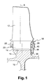
- the rotor of a compressor of a turbomachine comprises a plurality of rotor disks, one of which is partially represented in FIGS. 1 and 3, each disk 10 carrying a plurality of substantially radial blades 12 whose feet 14 are engaged in axial grooves 16 of the periphery of the disc 10.
- the feet 14 of the vanes are held radially in the grooves 16 of the disc by cooperation of shapes, these grooves 16 being for example dovetailed as shown in FIG. 3.
- the vanes 12 are immobilized axially in the grooves 16 by an annular flange. 18 mounted on the downstream face of the disk 10 and by a locking ring 20 mounted on the upstream face of the disk.
- the locking ring 20 is split and is compressed radially to be inserted into an annular groove 22 opening radially towards the inside of the upstream face of the disc 10. This ring 20 bears axially on the upstream ends of the feet 14 of the vanes of the disk 10, thus ensuring their axial retention in the upstream direction.
- the annular flange 18 is formed of angular sectors, for example five in number, and comprises upstream an annular flange 24 oriented radially outwards and housed in an annular groove 26 opening radially towards the inside the downstream face of the disk 10.
- the annular flange 24 of the flange is scalloped or crenellated, that is to say it has solid portions 28 formed alternately with hollow portions 30 regularly distributed around the axis flange.
- the radially outer portion 32 of the flange 18 is axially supported on the downstream ends of the feet 14 of the blades of the disc 10, thus ensuring their axial retention towards the downstream.
- the annular flange 18 comprises in its radially inner portion 34 an annular groove 36 opening axially upstream for the housing of an annular sealing ring 38 intended to be clamped axially between the downstream face of the disk and the bottom of the groove 36 and to be deformed radially outwardly in operation under the effect centrifugal forces.
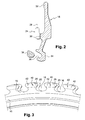
- the inner annular flange 40 of the groove 26 of the disc is scalloped or crenellated like the annular flange 24 of the flange 18, which makes it possible to engage the flange 24 of the flange 18 in the groove 26 of the disc by axial translation, when the solid parts 28 of the flange flange are aligned with the hollow portions of the flange 40 of the groove 26.
- the flange 18 is then immobilized axially by rotation in the groove 26 of the disc until the solid portions 28 of the rim 24 of the flange are aligned. with the solid portions 42 of the flange 40 of the groove and in axial support on these solid parts.
- the downstream flange 18 is immobilized in rotation about the axis of the disk 10 by means of tabs 44 formed on the downstream ends of the feet 14 of the blades and intended to fit with a small circumferential clearance in the hollow portions 30 of the annular flange 24 of the flange 18 ( Figures 1 and 4).
- the cleat 44 of each blade 12 is protruded on a downstream radial face 46 of the blade root 14 and has a parallelepipedal shape which is elongated in the circumferential direction and extends from a lateral edge to the other of the downstream face 46 of the foot.
- the catch 44 has a substantially radial downstream face 48 which is connected to the lateral faces 50 of the blade root 14 by faces 52, 53 intended to abut circumferentially on adjacent solid portions of the annular flange 24 of the flange for its stopping in rotation in the groove 26 of the disc.
- the faces 52, 53 may be aligned with the lateral faces 50 of the blade root.
- the face 52 of the cleat located on the right in the drawing, is intended to abut on a solid portion 28 of the scalloped rim of the flange to lock the flange 18 in a rotational direction (arrow 54 - to the left on the drawing) around the axis of the disk, and its face 53, located on the left in the drawing, is intended to abut on a solid portion 28 adjacent to the rim of the flange to lock it in rotation in the opposite direction of rotation (arrow 56 - to the right on the drawing) around the axis of the disc
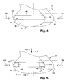
- the invention makes it possible to lighten this type of blade thanks to a smaller thickness of the central part of the cleat.
- the thickness of the cleat is the dimension of the cleat in a direction parallel to the axis of the disc.
- the central portion of the cleat has a small or no thickness and the lateral ends of the cleat which comprise the aforementioned abutment faces have a thickness substantially identical to that of the cleat of the prior art.
- the central part of the latch 144 has been removed by machining, the lateral ends of the latch 144 being substantially identical, and independent and at a circumferential distance from one another .
- Each end of the cleat 144 comprises a substantially radial downstream face 148 connected to the side face 150 of the nearest blade root by an abutment face 152, 153.
- the abutment face 152 of the cleat 144 located on the right in the drawing. , makes it possible to block the flange in the direction of rotation 154 around the axis of the disc, and the abutment face 153 of the latch 144, located on the left in the drawing, makes it possible to block the flange in the direction of rotation 156 around the axis of the disc.
- the length and the width of the cleat according to the invention are substantially identical to those of the cleat of the prior art.
- the length of the cleat means the dimension of the cleat in a circumferential direction relative to the axis of the disc, and the width of the cleat the dimension of the cleat in a radial direction relative to this axis.
- the length of the central portion of the cleat 144 is determined to firstly significantly reduce the mass of the blade 12 and secondly for the ends of the cleat retain sufficient mechanical strength not to degrade by abutment on solid parts of scalloped flange.
- the central portion lightened or removed from each cleat has a length at least equal to 3/4 or 4/5 of the length of the cleat.
Landscapes
- Engineering & Computer Science (AREA)
- Mechanical Engineering (AREA)
- General Engineering & Computer Science (AREA)
- Structures Of Non-Positive Displacement Pumps (AREA)
- Turbine Rotor Nozzle Sealing (AREA)
Applications Claiming Priority (1)
| Application Number | Priority Date | Filing Date | Title |
|---|---|---|---|
| FR0607510A FR2905139B1 (fr) | 2006-08-25 | 2006-08-25 | Aube de rotor d'une turbomachine |
Publications (3)
| Publication Number | Publication Date |
|---|---|
| EP1895103A2 true EP1895103A2 (de) | 2008-03-05 |
| EP1895103A3 EP1895103A3 (de) | 2009-01-21 |
| EP1895103B1 EP1895103B1 (de) | 2010-12-15 |
Family
ID=37507783
Family Applications (1)
| Application Number | Title | Priority Date | Filing Date |
|---|---|---|---|
| EP07290960A Active EP1895103B1 (de) | 2006-08-25 | 2007-07-31 | Rotor-Leitschaufel einer Strömungsmaschine |
Country Status (6)
| Country | Link |
|---|---|
| US (1) | US7850430B2 (de) |
| EP (1) | EP1895103B1 (de) |
| CA (1) | CA2598532C (de) |
| DE (1) | DE602007011169D1 (de) |
| FR (1) | FR2905139B1 (de) |
| RU (1) | RU2455496C2 (de) |
Cited By (4)
| Publication number | Priority date | Publication date | Assignee | Title |
|---|---|---|---|---|
| FR3091719A1 (fr) * | 2019-01-15 | 2020-07-17 | Safran Aircraft Engines | secteur de flasque d’etancheite de disque de rotor |
| FR3093131A1 (fr) * | 2019-02-22 | 2020-08-28 | Safran Aircraft Engines | Ensemble pour turbomachine |
| FR3095234A1 (fr) * | 2019-04-19 | 2020-10-23 | Safran Aircraft Engines | Ensemble de turbomachine comprenant un dispositif de limitation de temperature pour fond d’alveole non refroidi |
| FR3109604A1 (fr) | 2020-04-27 | 2021-10-29 | Safran Aircraft Engines | Roue aubagee a performances d’etancheite et de retention des aubes ameliorees |
Families Citing this family (6)
| Publication number | Priority date | Publication date | Assignee | Title |
|---|---|---|---|---|
| FR2929660B1 (fr) * | 2008-04-07 | 2012-11-16 | Snecma | Dispositif anti-usure pour rotor de turbomachine, bouchon formant dispositif anti-usure et rotor de compresseur de moteur a turbine a gaz comportant un bouchon anti-usure |
| US20100254807A1 (en) * | 2009-04-07 | 2010-10-07 | Honeywell International Inc. | Turbine rotor seal plate with integral flow discourager |
| US8007230B2 (en) * | 2010-01-05 | 2011-08-30 | General Electric Company | Turbine seal plate assembly |
| US8961141B2 (en) | 2011-08-29 | 2015-02-24 | United Technologies Corporation | Axial retention system for a bladed rotor with multiple blade types |
| JP2018104251A (ja) * | 2016-12-28 | 2018-07-05 | パナソニックIpマネジメント株式会社 | 炭素・金属複合材とそれが添加されたゴム組成物および樹脂組成物 |
| FR3092861B1 (fr) * | 2019-02-18 | 2023-02-10 | Safran Aircraft Engines | Ensemble de turbomachine comportant un taquet sur un jonc d'etancheite |
Citations (1)
| Publication number | Priority date | Publication date | Assignee | Title |
|---|---|---|---|---|
| FR2324873A1 (fr) | 1975-09-17 | 1977-04-15 | Snecma | Perfectionnements aux flasques de rotors de turbomachines |
Family Cites Families (9)
| Publication number | Priority date | Publication date | Assignee | Title |
|---|---|---|---|---|
| GB699582A (en) * | 1950-11-14 | 1953-11-11 | Rolls Royce | Improvements in or relating to gas-turbine engines |
| US3853425A (en) * | 1973-09-07 | 1974-12-10 | Westinghouse Electric Corp | Turbine rotor blade cooling and sealing system |
| US4453890A (en) * | 1981-06-18 | 1984-06-12 | General Electric Company | Blading system for a gas turbine engine |
| FR2535793B1 (fr) * | 1982-11-08 | 1987-04-10 | Snecma | Dispositif de verrouillage axial d'aubes de soufflante |
| FR2700807B1 (fr) * | 1993-01-27 | 1995-03-03 | Snecma | Système de rétention et d'étanchéité d'aubes engagées dans des brochages axiaux d'un disque de rotor. |
| GB2307279B (en) * | 1995-11-14 | 1999-11-17 | Rolls Royce Plc | A gas turbine engine |
| WO1997049921A1 (de) * | 1996-06-21 | 1997-12-31 | Siemens Aktiengesellschaft | Rotor für eine turbomaschine mit in nuten anbringbaren schaufeln sowie schaufel für einen rotor |
| RU2238412C1 (ru) * | 2003-04-28 | 2004-10-20 | Открытое акционерное общество "Научно-производственное объединение "Сатурн" | Рабочее колесо турбины |
| US7530791B2 (en) * | 2005-12-22 | 2009-05-12 | Pratt & Whitney Canada Corp. | Turbine blade retaining apparatus |
-
2006
- 2006-08-25 FR FR0607510A patent/FR2905139B1/fr active Active
-
2007
- 2007-07-31 DE DE602007011169T patent/DE602007011169D1/de active Active
- 2007-07-31 EP EP07290960A patent/EP1895103B1/de active Active
- 2007-08-07 US US11/835,117 patent/US7850430B2/en active Active
- 2007-08-22 CA CA2598532A patent/CA2598532C/fr active Active
- 2007-08-24 RU RU2007132178/06A patent/RU2455496C2/ru active
Patent Citations (1)
| Publication number | Priority date | Publication date | Assignee | Title |
|---|---|---|---|---|
| FR2324873A1 (fr) | 1975-09-17 | 1977-04-15 | Snecma | Perfectionnements aux flasques de rotors de turbomachines |
Cited By (5)
| Publication number | Priority date | Publication date | Assignee | Title |
|---|---|---|---|---|
| FR3091719A1 (fr) * | 2019-01-15 | 2020-07-17 | Safran Aircraft Engines | secteur de flasque d’etancheite de disque de rotor |
| US11365643B2 (en) | 2019-01-15 | 2022-06-21 | Safran Aircraft Engines | Rotor disc sealing flange sector |
| FR3093131A1 (fr) * | 2019-02-22 | 2020-08-28 | Safran Aircraft Engines | Ensemble pour turbomachine |
| FR3095234A1 (fr) * | 2019-04-19 | 2020-10-23 | Safran Aircraft Engines | Ensemble de turbomachine comprenant un dispositif de limitation de temperature pour fond d’alveole non refroidi |
| FR3109604A1 (fr) | 2020-04-27 | 2021-10-29 | Safran Aircraft Engines | Roue aubagee a performances d’etancheite et de retention des aubes ameliorees |
Also Published As
| Publication number | Publication date |
|---|---|
| EP1895103A3 (de) | 2009-01-21 |
| EP1895103B1 (de) | 2010-12-15 |
| FR2905139A1 (fr) | 2008-02-29 |
| RU2455496C2 (ru) | 2012-07-10 |
| US20080050245A1 (en) | 2008-02-28 |
| FR2905139B1 (fr) | 2012-09-28 |
| US7850430B2 (en) | 2010-12-14 |
| CA2598532C (fr) | 2014-05-27 |
| CA2598532A1 (fr) | 2008-02-25 |
| RU2007132178A (ru) | 2009-02-27 |
| DE602007011169D1 (de) | 2011-01-27 |
Similar Documents
| Publication | Publication Date | Title |
|---|---|---|
| EP1895103B1 (de) | Rotor-Leitschaufel einer Strömungsmaschine | |
| EP1918512B1 (de) | Ausgleichssystem für einen Strömungsmaschinenrotor | |
| EP1918511B1 (de) | Ausgleichssystem für einen Strömungsmaschinenrotor | |
| CA2625319A1 (fr) | Soufflante de turbomachine | |
| FR2918409A1 (fr) | Partie tournante de turbomachine comprenant des secteurs inter-aubes formant plateforme rapportes fixement sur un disque | |
| CA2647057C (fr) | Distributeur sectorise pour une turbomachine | |
| EP1950381A1 (de) | Rotorscheibe für ein Triebwerksfan | |
| WO2013150224A1 (fr) | Redresseur a calage variable pour compresseur de turbomachine comprenant deux anneaux internes | |
| EP1598524B1 (de) | Verfahren der Montage beschaufelter Rotorscheiben und Dämpfungsvorrichung dieser Schaufeln | |
| EP3201438B1 (de) | Laufschaufel einer turbomaschine mit einem flansch, der an einer sperrkerbe in der rotorscheibe anliegt | |
| EP2694781B1 (de) | Dichtring für eine turbinenstufe einer flugzeugturbomaschine mit geschlitzten drehschutzzapfen | |
| EP1469165B1 (de) | Verminderung des Blattspitzenspiels bei einer Gasturbine | |
| CA2557765C (fr) | Dispositif d'immobilisation d'un anneau de retention axiale d'une aube, disque de rotor et anneau de retention associes, et rotor et moteur d'aeronef les comportant | |
| FR3075869A1 (fr) | Roue mobile de turbine pour turbomachine d'aeronef, comprenant un anneau d'etancheite retenu radialement par des excroissances sur l'echasse des aubes | |
| FR3029960A1 (fr) | Roue a aubes avec joint radial pour une turbine de turbomachine | |
| FR3029961A1 (fr) | Roue a aubes avec becquets pour une turbine de turbomachine | |
| FR2993599A1 (fr) | Disque labyrinthe de turbomachine | |
| EP4352336A1 (de) | Rotorrad für ein flugzeugturbinentriebwerk | |
| EP1818507A1 (de) | Laufrad für Turbotriebwerke | |
| EP4402347A1 (de) | Laufschaufel für eine turbine eines turbinentriebwerks mit einer neigung mit vorsprüngen zum radialen halten der schaufel | |
| EP3935265B1 (de) | Rotor einer flugzeugturbomaschine mit dämpfungsvorrichtung | |
| FR3082232A1 (fr) | Systeme de maintien pour le demontage d'une roue a aubes | |
| FR3137411A1 (fr) | Rotor equipe d’aubes avec arret axial et turbomachine d’aéronef | |
| FR3094028A1 (fr) | Turbine comprenant un anneau d’etancheite rivete | |
| FR3163103A1 (fr) | Roue mobile aubagee de module de turbomachine d’aeronef, presentant une fonction amelioree de retention axiale d’aubes |
Legal Events
| Date | Code | Title | Description |
|---|---|---|---|
| PUAI | Public reference made under article 153(3) epc to a published international application that has entered the european phase |
Free format text: ORIGINAL CODE: 0009012 |
|
| AK | Designated contracting states |
Kind code of ref document: A2 Designated state(s): AT BE BG CH CY CZ DE DK EE ES FI FR GB GR HU IE IS IT LI LT LU LV MC MT NL PL PT RO SE SI SK TR |
|
| AX | Request for extension of the european patent |
Extension state: AL BA HR MK YU |
|
| PUAL | Search report despatched |
Free format text: ORIGINAL CODE: 0009013 |
|
| AK | Designated contracting states |
Kind code of ref document: A3 Designated state(s): AT BE BG CH CY CZ DE DK EE ES FI FR GB GR HU IE IS IT LI LT LU LV MC MT NL PL PT RO SE SI SK TR |
|
| AX | Request for extension of the european patent |
Extension state: AL BA HR MK RS |
|
| 17P | Request for examination filed |
Effective date: 20090709 |
|
| AKX | Designation fees paid |
Designated state(s): DE FR GB |
|
| 17Q | First examination report despatched |
Effective date: 20100208 |
|
| GRAP | Despatch of communication of intention to grant a patent |
Free format text: ORIGINAL CODE: EPIDOSNIGR1 |
|
| GRAS | Grant fee paid |
Free format text: ORIGINAL CODE: EPIDOSNIGR3 |
|
| GRAA | (expected) grant |
Free format text: ORIGINAL CODE: 0009210 |
|
| AK | Designated contracting states |
Kind code of ref document: B1 Designated state(s): DE FR GB |
|
| REG | Reference to a national code |
Ref country code: GB Ref legal event code: FG4D Free format text: NOT ENGLISH |
|
| REF | Corresponds to: |
Ref document number: 602007011169 Country of ref document: DE Date of ref document: 20110127 Kind code of ref document: P |
|
| PLBE | No opposition filed within time limit |
Free format text: ORIGINAL CODE: 0009261 |
|
| STAA | Information on the status of an ep patent application or granted ep patent |
Free format text: STATUS: NO OPPOSITION FILED WITHIN TIME LIMIT |
|
| 26N | No opposition filed |
Effective date: 20110916 |
|
| REG | Reference to a national code |
Ref country code: DE Ref legal event code: R097 Ref document number: 602007011169 Country of ref document: DE Effective date: 20110916 |
|
| REG | Reference to a national code |
Ref country code: FR Ref legal event code: PLFP Year of fee payment: 10 |
|
| REG | Reference to a national code |
Ref country code: FR Ref legal event code: PLFP Year of fee payment: 11 |
|
| REG | Reference to a national code |
Ref country code: FR Ref legal event code: CD Owner name: SNECMA, FR Effective date: 20170713 |
|
| REG | Reference to a national code |
Ref country code: FR Ref legal event code: PLFP Year of fee payment: 12 |
|
| PGFP | Annual fee paid to national office [announced via postgrant information from national office to epo] |
Ref country code: DE Payment date: 20250722 Year of fee payment: 19 |
|
| PGFP | Annual fee paid to national office [announced via postgrant information from national office to epo] |
Ref country code: GB Payment date: 20250724 Year of fee payment: 19 |
|
| PGFP | Annual fee paid to national office [announced via postgrant information from national office to epo] |
Ref country code: FR Payment date: 20250722 Year of fee payment: 19 |