EP1894736A2 - Security element with a color-shift effect and method for producing said security element - Google Patents
Security element with a color-shift effect and method for producing said security element Download PDFInfo
- Publication number
- EP1894736A2 EP1894736A2 EP07016548A EP07016548A EP1894736A2 EP 1894736 A2 EP1894736 A2 EP 1894736A2 EP 07016548 A EP07016548 A EP 07016548A EP 07016548 A EP07016548 A EP 07016548A EP 1894736 A2 EP1894736 A2 EP 1894736A2
- Authority
- EP
- European Patent Office
- Prior art keywords
- layer
- motif
- layers
- security element
- color
- Prior art date
- Legal status (The legal status is an assumption and is not a legal conclusion. Google has not performed a legal analysis and makes no representation as to the accuracy of the status listed.)
- Granted
Links
- 230000000694 effects Effects 0.000 title claims abstract description 46
- 238000004519 manufacturing process Methods 0.000 title claims abstract description 15
- 238000000034 method Methods 0.000 claims abstract description 45
- 238000004132 cross linking Methods 0.000 claims abstract description 29
- 239000007788 liquid Substances 0.000 claims abstract description 10
- 239000010410 layer Substances 0.000 claims description 216
- 239000002178 crystalline material Substances 0.000 claims description 30
- 230000003098 cholesteric effect Effects 0.000 claims description 23
- 239000002904 solvent Substances 0.000 claims description 12
- 238000007639 printing Methods 0.000 claims description 11
- 230000005855 radiation Effects 0.000 claims description 10
- 239000003795 chemical substances by application Substances 0.000 claims description 7
- 239000011248 coating agent Substances 0.000 claims description 6
- 239000004988 Nematic liquid crystal Substances 0.000 claims description 5
- 238000000576 coating method Methods 0.000 claims description 5
- 239000003973 paint Substances 0.000 claims description 5
- 239000000758 substrate Substances 0.000 claims description 5
- XKRFYHLGVUSROY-UHFFFAOYSA-N Argon Chemical compound [Ar] XKRFYHLGVUSROY-UHFFFAOYSA-N 0.000 claims description 4
- CURLTUGMZLYLDI-UHFFFAOYSA-N Carbon dioxide Chemical compound O=C=O CURLTUGMZLYLDI-UHFFFAOYSA-N 0.000 claims description 4
- 239000012298 atmosphere Substances 0.000 claims description 4
- 238000000605 extraction Methods 0.000 claims description 4
- 239000002346 layers by function Substances 0.000 claims description 4
- IJGRMHOSHXDMSA-UHFFFAOYSA-N Atomic nitrogen Chemical compound N#N IJGRMHOSHXDMSA-UHFFFAOYSA-N 0.000 claims description 2
- 229910052786 argon Inorganic materials 0.000 claims description 2
- 239000001569 carbon dioxide Substances 0.000 claims description 2
- 229910002092 carbon dioxide Inorganic materials 0.000 claims description 2
- 238000007766 curtain coating Methods 0.000 claims description 2
- 238000007646 gravure printing Methods 0.000 claims description 2
- 239000011261 inert gas Substances 0.000 claims description 2
- JCXJVPUVTGWSNB-UHFFFAOYSA-N nitrogen dioxide Inorganic materials O=[N]=O JCXJVPUVTGWSNB-UHFFFAOYSA-N 0.000 claims description 2
- 238000007650 screen-printing Methods 0.000 claims description 2
- 238000010345 tape casting Methods 0.000 claims description 2
- 239000000463 material Substances 0.000 abstract description 15
- 230000008569 process Effects 0.000 abstract description 3
- 230000003993 interaction Effects 0.000 description 13
- 239000004986 Cholesteric liquid crystals (ChLC) Substances 0.000 description 8
- 239000004922 lacquer Substances 0.000 description 6
- 239000004973 liquid crystal related substance Substances 0.000 description 6
- 230000008859 change Effects 0.000 description 5
- 238000013461 design Methods 0.000 description 5
- 239000012939 laminating adhesive Substances 0.000 description 5
- 238000006073 displacement reaction Methods 0.000 description 3
- 230000008901 benefit Effects 0.000 description 2
- 230000001419 dependent effect Effects 0.000 description 2
- 238000011161 development Methods 0.000 description 2
- 230000018109 developmental process Effects 0.000 description 2
- 230000012447 hatching Effects 0.000 description 2
- 238000001465 metallisation Methods 0.000 description 2
- 238000007699 photoisomerization reaction Methods 0.000 description 2
- 230000000007 visual effect Effects 0.000 description 2
- 229920002799 BoPET Polymers 0.000 description 1
- 229920000106 Liquid crystal polymer Polymers 0.000 description 1
- 241000244206 Nematoda Species 0.000 description 1
- 230000009471 action Effects 0.000 description 1
- 238000013459 approach Methods 0.000 description 1
- 229910052799 carbon Inorganic materials 0.000 description 1
- 238000010276 construction Methods 0.000 description 1
- 238000001816 cooling Methods 0.000 description 1
- 230000007423 decrease Effects 0.000 description 1
- 239000011888 foil Substances 0.000 description 1
- 238000002156 mixing Methods 0.000 description 1
- 239000000203 mixture Substances 0.000 description 1
- 230000010287 polarization Effects 0.000 description 1
- 229920006254 polymer film Polymers 0.000 description 1
- 238000006116 polymerization reaction Methods 0.000 description 1
- 238000012545 processing Methods 0.000 description 1
- 239000002344 surface layer Substances 0.000 description 1
- 230000002277 temperature effect Effects 0.000 description 1
- 238000012546 transfer Methods 0.000 description 1
- 238000012795 verification Methods 0.000 description 1
Images


Classifications
-
- B—PERFORMING OPERATIONS; TRANSPORTING
- B41—PRINTING; LINING MACHINES; TYPEWRITERS; STAMPS
- B41M—PRINTING, DUPLICATING, MARKING, OR COPYING PROCESSES; COLOUR PRINTING
- B41M3/00—Printing processes to produce particular kinds of printed work, e.g. patterns
- B41M3/14—Security printing
-
- B—PERFORMING OPERATIONS; TRANSPORTING
- B42—BOOKBINDING; ALBUMS; FILES; SPECIAL PRINTED MATTER
- B42D—BOOKS; BOOK COVERS; LOOSE LEAVES; PRINTED MATTER CHARACTERISED BY IDENTIFICATION OR SECURITY FEATURES; PRINTED MATTER OF SPECIAL FORMAT OR STYLE NOT OTHERWISE PROVIDED FOR; DEVICES FOR USE THEREWITH AND NOT OTHERWISE PROVIDED FOR; MOVABLE-STRIP WRITING OR READING APPARATUS
- B42D25/00—Information-bearing cards or sheet-like structures characterised by identification or security features; Manufacture thereof
- B42D25/30—Identification or security features, e.g. for preventing forgery
- B42D25/36—Identification or security features, e.g. for preventing forgery comprising special materials
- B42D25/364—Liquid crystals
-
- B—PERFORMING OPERATIONS; TRANSPORTING
- B42—BOOKBINDING; ALBUMS; FILES; SPECIAL PRINTED MATTER
- B42D—BOOKS; BOOK COVERS; LOOSE LEAVES; PRINTED MATTER CHARACTERISED BY IDENTIFICATION OR SECURITY FEATURES; PRINTED MATTER OF SPECIAL FORMAT OR STYLE NOT OTHERWISE PROVIDED FOR; DEVICES FOR USE THEREWITH AND NOT OTHERWISE PROVIDED FOR; MOVABLE-STRIP WRITING OR READING APPARATUS
- B42D25/00—Information-bearing cards or sheet-like structures characterised by identification or security features; Manufacture thereof
- B42D25/30—Identification or security features, e.g. for preventing forgery
- B42D25/355—Security threads
-
- C—CHEMISTRY; METALLURGY
- C09—DYES; PAINTS; POLISHES; NATURAL RESINS; ADHESIVES; COMPOSITIONS NOT OTHERWISE PROVIDED FOR; APPLICATIONS OF MATERIALS NOT OTHERWISE PROVIDED FOR
- C09K—MATERIALS FOR MISCELLANEOUS APPLICATIONS, NOT PROVIDED FOR ELSEWHERE
- C09K19/00—Liquid crystal materials
- C09K19/02—Liquid crystal materials characterised by optical, electrical or physical properties of the components, in general
-
- B42D2033/26—
-
- B42D2035/24—
Definitions
- the invention relates to a method for producing a security element with farbkippender motif layer for security papers, documents of value and the like.
- Valuables such as branded goods or documents of value, are often provided with security elements for the purpose of protection, which allow verification of the authenticity of the object of value and at the same time serve as protection against unauthorized reproduction.
- security elements for the purpose of protection, which allow verification of the authenticity of the object of value and at the same time serve as protection against unauthorized reproduction.
- the special properties of liquid-crystalline materials are exploited for this purpose, and above all the viewing angle-dependent color impression and the light-polarizing effect of the liquid crystals.
- cholesteric liquid crystal layers with different adjacent color shift effects are produced by a targeted temperature action and the resulting local change in the pitch of the helical structure.
- the same effect can by a subsequent local change in the Verdrillerkonzentration of the cholesteric material by targeted photoisomerization of a photoisomerizable Verdrillers be achieved.
- the publication EP 1 295 929 A2 describes, for example, an anisotropic polymer film comprising a polymerized chiral liquid crystalline material having a helical structure.
- the liquid crystalline material contains at least two photoisomerizable chiral components with different directions of rotation, from which a chiral component can be converted by means of radiation into a state with different pitch.
- the present invention seeks to provide a method of the type mentioned above, which avoids the disadvantages of the prior art, or at least reduced.
- a simple method for producing acereiements be given with farbkippender motif layer that allows several adjacent different color shift effects.
- the respective layer In incomplete crosslinking, the respective layer has a first low degree of crosslinking. In complete crosslinking, the respective layer has a second high degree of crosslinking.
- the absolute values depend strongly on the material used.
- the incomplete crosslinking of the first non-chiral liquid crystal layer allows an unexpected interaction with the subsequently applied chiral liquid crystal layer, which allows sharply limited, local changes in their color-shifting properties.
- a layer of a nematic liquid-crystalline material is applied.
- the first layer is preferably applied in the form of a first motif, the first motif being formed in particular by regions of different layer thickness of the non-chiral liquid-crystalline material.
- a layer of a cholesteric liquid-crystalline material is advantageously applied.
- the cholesteric liquid-crystalline material is expediently formed by combining a nematic liquid-crystal system with a twisting agent. Since a motif is already formed by the interaction of a structured applied first layer with the second layer, the second layer is suitably applied over the entire surface in step c).
- step b) is advantageously carried out so strongly that the first layer is tack-free and windable thereafter, but the first layer has not yet completely polymerized.
- the second layer can also be incompletely crosslinked in step d) so that it is tack-free and windable.
- Their color-shifting properties can then be further modified by applying a solvent-containing coating agent, as explained below.
- the incomplete crosslinking of the first and / or second layer is achieved in particular by crosslinking at a low temperature, in particular at a temperature of 30 ° C. or less, for example at a temperature of about 20 ° C.
- the first and / or second layer are completely crosslinked in a later process step e).
- Complete crosslinking of the first and / or second layer is achieved by crosslinking at an elevated temperature, preferably at a temperature above 30 ° C., more preferably above 50 ° C.
- step a) at least one further layer of a liquid-crystalline material is initially applied to the Carrier applied, the at least one further layer fully crosslinked and then applied the first layer on the fully crosslinked, at least one further layer.
- a layer of a nematic liquid-crystalline material is preferably applied as at least one further layer, particularly preferably in the form of a second motif.
- the second motif of the at least one further layer can be a hidden motif which, when viewed with the naked eye, is practically invisible and only appears when viewed with a polarizer.
- the second layer is only incompletely crosslinked in step d), an extraction agent, in particular a solvent-containing lacquer, is applied to the second layer at least in some areas, and the second layer is completely crosslinked after application of the extraction agent.
- the extractant can be applied over the entire surface or in the form of a third motif on the second layer. Also, the extractant can locally change the color shift effect of the incompletely crosslinked second layer in the manner described in more detail below, thereby providing further possibilities for varying the visual design of the security element.
- the incomplete crosslinking of the layers is preferably carried out by exposure to UV radiation at low temperature, in particular at a temperature below 30 ° C.
- the complete crosslinking of the layers is advantageously carried out by exposure to UV radiation at elevated temperature, in particular at a temperature above 30 ° C.
- the UV exposure to crosslinking is expediently carried out in an inert gas atmosphere, in particular an argon, nitrogen or carbon dioxide atmosphere.
- liquid-crystalline layers are advantageously printed by gravure printing, screen printing, flexographic printing, Knifecoating or curtain coating, wherein in particular the first and second layer can also be applied with different printing techniques.
- One or more further layers are advantageously applied to the second layer, which serve to protect the security element or one of its partial layers, to improve the adhesion of individual layers or to further increase the security against counterfeiting.
- the layer sequence is advantageously transferred to a target substrate, for example a security thread structure.
- the target substrate expediently has a dark, in particular a black coating, in order to increase the visual conspicuousness of the color-shift effects.
- the security element is preferably further equipped with one or more functional layers, in particular with layers with visually and / or machine-detectable security features.
- the functional layers can be formed by full-surface or partial reflective, high-refractive, color-shifting, polarizing, phase-shifting layers, opaque or transparent conductive layers, soft or hard magnetic layers and / or fluorescent or phosphorescent layers.
- the invention also includes a security element with a color-shifting motif layer for security papers, documents of value and the like, comprising a first layer of a non-chiral liquid-crystalline material and a color-shifting motif layer applied to the first layer a chiral liquid crystalline material which can be prepared in the manner described above.
- the color-shifting motif layer preferably has at least two motif areas with different color-shift effects.
- the first layer is preferably applied in the form of the desired motif, while the color-shifting motif layer is advantageously applied over the entire surface.
- the invention further comprises a security paper for the production of documents of value or the like as well as a value document, such as a banknote, an identification card or the like, wherein security paper or security document are provided with a security element of the type described above.
- FIG. 1 shows a schematic representation of a banknote 10, which is provided with a security element 12 according to the invention with a multi-colored, color-shifting motif layer.
- alternating strip-shaped motif areas 14 and 16 are shown in which the security element 12 each has a different color-shift effect.
- the color impression of the motif strips 14 may change from green to blue when the security element is tilted from red to green and the color impression of the motif strips 16.
- motifs in particular arbitrary patterns, characters or codings, can be used instead of the strip motif used for illustration different color impressions are designed.
- edge sharpness of the motifs the designer a variety of possible designs available.
- a first layer 22 of nematic liquid-crystalline material in the form of the desired motif is first printed onto a carrier film 20, for example a PET film of good surface quality.
- a carrier film 20 for example a PET film of good surface quality.
- the low temperature T 1 is in particular below 30 ° C, in the embodiment at 20 ° C. This low temperature can be achieved, for example, by guiding the carrier film over a correspondingly adjusted cooling roller during UV exposure.
- the first layer 22 is crosslinked so much that it is tack-free and windable, but the crosslinking has not yet completely occurred, in order to enable the interaction described below with the subsequently applied second layer.
- a second layer 24 of a cholesteric liquid-crystalline material is printed over its entire surface.
- the cholesteric second layer 24 exhibits a color shift effect in the finished security element in the layer regions 26 without underlying first layer 22 with a certain design wavelength of the reflection maximum.
- the color shift effect of the unaffected second layer 24 can show a color impression that changes from green to blue when the security element is tilted out of the vertical.
- the layer regions 28 in which the carrier film 20 is already printed with the partially crosslinked first layer 22 an interaction between the newly applied cholesteric liquid crystal material and the underlying Nematen now takes place, resulting in a shift of the reflection maximum of the second layer 24 in the long-wave range shows.
- the layer regions 28 have a color shift effect after interaction, in which the color impression changes from red to green when the security element is tilted out of the vertical.
- the long wavelength shift of the reflection maximum is due to a mixing of the applied cholesteric liquid crystal material with the not yet fully crosslinked nematic liquid crystal material during the printing process. Due to the low polymerization temperature T 1 , the degree of crosslinking of the nemate layer 22 initially remains so low that, when the second cholesteric layer 24 is being printed, the first layer 22 is dissolved.
- the concentration of the twisting agent in the second layer 24 decreases due to the mixture of the printed cholesteric liquid crystal material with the nematic liquid crystals.
- the pitch height increases as a result and the reflection maximum is shifted accordingly in the long-wave.
- the layer regions 26 without underlying first layer 24 there is no interaction and thus no shift of the reflection maximum, where a color shift effect corresponding to the design of the cholesteric layer 24 is rather observed.
- the first and second layers 22, 24 are now completely crosslinked by UV exposure at a higher temperature T 2 , which is indicated by the cross-hatching in FIG. 3 (d).
- T 2 a temperature above 50 ° C.
- the two different color shift effects in the layer regions 26 and 28 of the second layer 24 are thereby permanently fixed.
- the layer sequence of FIG. 3 (d) may be coated with a laminating adhesive and transferred to a desired target substrate.
- the carrier film 20 can be removed or form part of the finished security element.
- the achievable edge sharpness of the different adjacent color shift effects of the layer regions 26 and 28 is determined in the present invention essentially only by the achievable high edge sharpness of the printed Nematen für 22.
- the different color-shifting motif areas 26, 28 can therefore also have a very high edge sharpness.
- the cholesteric layer 24 of these can be more or less influenced. If the cholesteric layer 24 is designed, for example, for a color shift effect from blue to ultraviolet, differently strong color shifts into the long wave can be achieved by different layer thicknesses of the nematode layer 22, in extreme cases up to a color shift effect from infrared to red. The different color shift effects can be used in one security element be realized with a single cholesteric layer 24.
- the interaction of the two layers according to the invention is unexpected since the first layer after the incomplete crosslinking is already tack-free and therefore windable.
- the effect can, for example, also be used to advantage in cases where there is no possibility of printing wet-on-wet. Since the printed liquid crystal layers each require a certain alignment distance, it is difficult to find a printing press with several successive printing units and sufficiently long alignment distances.
- the method according to the invention offers great freedom in the choice of the printing methods, since the first and second layers can be produced with different printing methods and even on different printing machines because of the windability of the first layer.
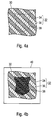
- the security element 30 of FIG. 4 has an open first motif 32 formed by regions 34 and 36 having different color-shift effects, as shown in FIG. 4 (a).
- the security element 30 includes a hidden second motif 38 that when viewed is practically not visible to the naked eye and only clearly appears when viewed with a polarizer 40, as shown in Fig. 4 (b).
- a third layer 42 of a nematic liquid crystalline material in the form of the desired hidden motif, here the coat of arms motif of FIG. 4 (b), is first printed on a carrier foil 20 and exposed to UV light. Radiation at a high temperature T 2 completely crosslinked.
- This third layer 42 which serves to create the hidden motif, is applied in a varying layer thickness, which ensures good contrast in the polarizer motif.
- thickness variation between a layer thickness d and the layer thickness zero shown in FIG. 5 (a) thickness variation between a first and a second layer thickness d 1 or d 2 , or between more than two different layer thicknesses, can of course also be used for the third layer 42 Use come.
- a first layer 22 of nematic liquid crystal material in the form of the desired open motif is printed on the third layer 42.
- the first layer 22 is crosslinked only incompletely by exposure to UV radiation at a low temperature T 1 .
- the first layer 22 is made thinner than the third layer 42, so that it exerts less effect on the polarization of the transmitted light in the finished security element.
- a second layer 24 of a cholesteric liquid-crystalline material is then printed over the whole area.
- the interaction of the cholesteric layer 24 with the underlying, incompletely crosslinked Nematen layer 22 results in two layer regions 26, 28 with a different color shift effect, the layer regions 26 and 28 together forming the open motif.
- This resulting situation is shown schematically in Fig. 5 (c).
- a corresponding interaction of the cholesteric layer 24 with the third layer 42 can not take place, since the third layer 42 is already completely cured during the application of the second layer 24 and therefore, unlike the first layer 22, is not dissolved during printing.
- first and second layers 22, 24 are fully crosslinked by UV exposure at a higher temperature T 2 , as shown in Fig. 5 (d), to permanently fix the different color shift effects of the first subject 26, 28. Further known process steps for the completion of the security element may follow.
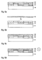
- FIG. 6 illustrates a further possibility according to the invention for subsequently selectively influencing the color-shift effect of cholesteric liquid-crystal layers:
- the laminating adhesive as shown in FIG. 6 (b)
- a shift of the color shift effects of the layer regions 26, 28 into the short wavelength is observed, which is shown in FIG Fig. 6 (c) is indicated by the narrower hatching.
- This short-wave shift of the color shift effects is subsequently fixed by crosslinking at the higher temperature T 2 , as shown in FIG. 6 (d).
- the security element of FIG. 6 (d) thus shows the first motif with color shift effects shifted together into short-wavelength in the regions 26, 28.
- the short-wave shift of the color shift effects can also be achieved by the application of another solvent-containing coating material, for example a solvent-containing paint.
- the solvent-containing coating material can in particular also be applied in the form of a further motif in order to achieve a locally different change in the color-shift effects.
- This short-wave displacement can also be combined with the above-described long-wave displacement by an incompletely crosslinked Nematen slaughter, so that a plurality of different color shift effects can be realized in a single security element by simple measures, as illustrated below with reference to the illustration of FIG. 7.
- FIG. 7 shows an exemplary construction of a security thread 60 in which the layer sequence of the liquid crystal layers is already transferred to a thread base structure 62 and the carrier film used for the production was replaced.
- the sequence of the liquid crystal layers shown is therefore inverted compared to the representations of FIGS. 3, 5 and 6.
- the security thread 60 has a third layer 42 of a nematic liquid crystalline material in the form of a desired second (hidden) motif, a first layer 22 of nematic liquid crystalline material in the form of a desired first (open) motif, a full surface applied second layer 24 of a cholesteric liquid-crystalline material, a solvent-containing lacquer layer 52 applied in the form of a desired third (open) motif, a lacquer layer 54 applied over the entire area, a laminating adhesive layer 56 and a yarn base structure 62.
- the thread base structure 62 follows per se known designs and may, for example, contain a negative-type metallization, a raster metallization, a black coating with negative writing and / or magnetic layer regions.
- This third layer 42 was fully crosslinked in the manufacture of the security thread 62. after application at a higher temperature, as described in connection with FIG. 5.
- the first layer 22 was only incompletely crosslinked after application at a low temperature.
- the second layer 24 was printed over the entire area and also the second layer 24 was only partially crosslinked at a low temperature. Then, the solvent-containing paint layer 52 was applied to the incompletely crosslinked second layer 24.
- the cholesteric second layer 24 is therefore doubly influenced in the embodiment of FIG. 7: on the one hand by the interaction with the incompletely crosslinked Nematen layer 22, which leads to a local shift of the Farbkipp bins in the long-wave, on the other hand by the interaction with the solvent-containing paint layer, which results in a local shift of the color shift effect of the incompletely crosslinked cholesteric layer 24 into the short wavelength.
- the color-shift effect of the cholesteric layer 24 is shifted into short-wavelength by the interaction with the solvent-containing lacquer layer 52, as explained in FIG. 6.
- the short-wave and the long-wave shift overlap to an effective Total color shift, which depends on the relative sizes of the two components.
- the extent of the shift to the long-wave region B 2 and B 4 , and the extent of the shift to the short-wave region B 3 and B 4 can be adjusted in each case by the layer thickness of the first layer 22 or the solvent-containing paint layer 52 ,
- the layers 22 and 52 can also have different thicknesses in subregions, so that different degrees of displacement can be realized in a single security element.
- the areas B 5 to B 8 differ from the areas B 1 to B 4 only in that they are applied to the third layer 42. They therefore show the same appearance as the areas B 1 to B 4 when viewed without aids, but when viewed in the polarizer clearly stand out from them, as already explained in the description of FIG. 4.
- the invention provides the designer with a variety of ways to combine sharply defined open and hidden motifs with different color shift effects in a single security element.
Abstract
Description
Die Erfindung betrifft ein Verfahren zum Herstellen eines Sicherheitselements mit farbkippender Motivschicht für Sicherheitspapiere, Wertdokumente und dergleichen.The invention relates to a method for producing a security element with farbkippender motif layer for security papers, documents of value and the like.
Wertgegenstände, wie etwa Markenartikel oder Wertdokumente, werden zur Absicherung oft mit Sicherheitselementen ausgestattet, die eine Überprüfung der Echtheit des Wertgegenstands gestatten und die zugleich als Schutz vor unerlaubter Reproduktion dienen. Vielfach werden für diesen Zweck die besonderen Eigenschaften von flüssigkristallinen Materialien ausgenutzt, und dabei vor allem der betrachtungswinkelabhängige Farbeindruck und die lichtpolarisierende Wirkung der Flüssigkristalle.Valuables, such as branded goods or documents of value, are often provided with security elements for the purpose of protection, which allow verification of the authenticity of the object of value and at the same time serve as protection against unauthorized reproduction. In many cases, the special properties of liquid-crystalline materials are exploited for this purpose, and above all the viewing angle-dependent color impression and the light-polarizing effect of the liquid crystals.
Besonders die Erzeugung von mehrfarbigen farbkippenden Motiven, also von Motiven, deren Motivbereiche unterschiedliche Farbkippeffekte aufweisen, ist derzeit allerdings noch mit praktischen Schwierigkeiten verbunden. Beispielsweise beschreibt die Druckschrift
Bei einem anderen Ansatz werden cholesterische Flüssigkristallschichten mit unterschiedlichen nebeneinanderliegenden Farbkippeffekten durch eine gezielte Temperatureinwirkung und die daraus resultierende lokale Änderung der Ganghöhe der helikalen Struktur hergestellt. Die gleiche Wirkung kann durch eine nachträgliche lokale Veränderung der Verdrillerkonzentration des cholesterischen Materials durch gezielte Photoisomerisierung eines photoisomerisierbaren Verdrillers erzielt werden.In another approach, cholesteric liquid crystal layers with different adjacent color shift effects are produced by a targeted temperature action and the resulting local change in the pitch of the helical structure. The same effect can by a subsequent local change in the Verdrillerkonzentration of the cholesteric material by targeted photoisomerization of a photoisomerizable Verdrillers be achieved.
Die Druckschrift
Durch eine lokale Temperatureinwirkung können allerdings derzeit nur vergleichsweise unscharfe Motivbilder erzeugt werden. Die lokale Veränderung der Verdrillerkonzentration durch Photoisomerisierung erfordert eine gezielte lokale Belichtung mit UV-Strahlung, was insbesondere in einem Rolle-zu-Rolle-Prozess nur schwer zu realisieren ist.By a local temperature effect, however, only comparatively blurred motif images can currently be generated. The local variation of the twisting concentration by photoisomerization requires a targeted local exposure to UV radiation, which is difficult to realize, especially in a roll-to-roll process.
Ausgehend davon liegt der Erfindung die Aufgabe zugrunde, ein Verfahren der eingangs genannten Art anzugeben, das die Nachteile des Stands der Technik vermeidet oder zumindest reduziert. Insbesondere soll ein einfaches Verfahren zur Herstellung eines Sicherheitseiements mit farbkippender Motivschicht angegeben werden, das mehrere nebeneinanderliegende unterschiedliche Farbkippeffekte ermöglicht.Based on this, the present invention seeks to provide a method of the type mentioned above, which avoids the disadvantages of the prior art, or at least reduced. In particular, a simple method for producing a Sicherheitseiements be given with farbkippender motif layer that allows several adjacent different color shift effects.
Diese Aufgabe wird durch das Verfahren mit den Merkmalen des Hauptanspruchs gelöst. Ein entsprechendes Sicherheitselement, ein Sicherheitspapier sowie ein Wertdokument sind in den nebengeordneten Ansprüchen angegeben. Weiterbildungen der Erfindung sind Gegenstand der Unteransprüche.This object is achieved by the method having the features of the main claim. A corresponding security element, a security paper and a value document are specified in the independent claims. Further developments of the invention are the subject of the dependent claims.
Gemäß der Erfindung wird bei einem gattungsgemäßen Verfahren
- a) auf einen Träger eine erste Schicht aus einem nicht-chiralen flüssigkristallinen Material aufgebracht,
- b) die erste Schicht nur unvollständig vernetzt,
- c) eine zweite Schicht aus einem chiralen flüssigkristallinen Material mit einem Farbkippeffekt auf die erste Schicht aufgebracht, und
- d) die zweite Schicht unvollständig oder vollständig vernetzt.
- a) applied to a carrier a first layer of a non-chiral liquid-crystalline material,
- b) the first layer is only incompletely crosslinked,
- c) a second layer of a chiral liquid crystalline material with a color shift effect applied to the first layer, and
- d) the second layer is incomplete or fully crosslinked.
Bei der unvollständigen Vernetzung weist die jeweilige Schicht einen ersten niedrigen Vernetzungsgrad auf. Bei der vollständigen Vernetzung weist die jeweilige Schicht einen zweiten hohen Vernetzungsgrad auf. Die absoluten Werte hängen dabei stark vom verwendeten Material ab.In incomplete crosslinking, the respective layer has a first low degree of crosslinking. In complete crosslinking, the respective layer has a second high degree of crosslinking. The absolute values depend strongly on the material used.
Wie nachfolgend genauer erläutert, erlaubt die unvollständige Vernetzung der ersten nicht-chiralen Flüssigkristallschicht eine unerwartete Wechselwirkung mit der anschließend aufgebrachten chiralen Flüssigkristallschicht, die scharf begrenzte, lokale Änderungen deren farbkippender Eigenschaften ermöglicht.As explained in more detail below, the incomplete crosslinking of the first non-chiral liquid crystal layer allows an unexpected interaction with the subsequently applied chiral liquid crystal layer, which allows sharply limited, local changes in their color-shifting properties.
Vorzugsweise wird in Schritt a) eine Schicht aus einem nematischen flüssigkristallinen Material aufgebracht. Bevorzugt wird die erste Schicht dabei in Form eines ersten Motivs aufgebracht, wobei das erste Motiv insbesondere durch Bereiche unterschiedlicher Schichtdicke des nicht-chiralen flüssigkristallinen Materials gebildet wird.Preferably, in step a) a layer of a nematic liquid-crystalline material is applied. In this case, the first layer is preferably applied in the form of a first motif, the first motif being formed in particular by regions of different layer thickness of the non-chiral liquid-crystalline material.
In Schritt c) wird mit Vorteil eine Schicht aus einem cholesterischen flüssigkristallinen Material aufgebracht. Das cholesterische flüssigkristalline Material wird dabei zweckmäßig durch Kombination eines nematischen Flüssigkristallsystems mit einem Verdriller gebildet. Da ein Motiv bereits durch die Wechselwirkung einer strukturiert aufgebrachten ersten Schicht mit der zweiten Schicht entsteht, wird die zweite Schicht in Schritt c) zweckmäßig vollflächig aufgebracht.In step c), a layer of a cholesteric liquid-crystalline material is advantageously applied. The cholesteric liquid-crystalline material is expediently formed by combining a nematic liquid-crystal system with a twisting agent. Since a motif is already formed by the interaction of a structured applied first layer with the second layer, the second layer is suitably applied over the entire surface in step c).
Die Vernetzung in Schritt b) wird mit Vorteil so stark ausgeführt, dass die erste Schicht danach tackfrei und wickelbar ist, die erste Schicht aber noch nicht vollständig polymerisiert ist. Auch die zweite Schicht kann in Schritt d) nur so unvollständig vernetzt werden, dass sie tackfrei und wickelbar ist. Ihre farbkippenden Eigenschaften können dann durch Aufbringen eines lösungsmittelhaltigen Beschichtungsmittels noch modifiziert werden, wie weiter unten erläutert.The crosslinking in step b) is advantageously carried out so strongly that the first layer is tack-free and windable thereafter, but the first layer has not yet completely polymerized. The second layer can also be incompletely crosslinked in step d) so that it is tack-free and windable. Their color-shifting properties can then be further modified by applying a solvent-containing coating agent, as explained below.
Die unvollständige Vernetzung der ersten und/oder zweiten Schicht wird insbesondere durch Vernetzung bei einer niedrigen Temperatur, insbesondere bei einer Temperatur von 30 °C oder weniger, beispielsweise bei einer Temperatur von etwa 20 °C erreicht.The incomplete crosslinking of the first and / or second layer is achieved in particular by crosslinking at a low temperature, in particular at a temperature of 30 ° C. or less, for example at a temperature of about 20 ° C.
Mit Vorteil werden die erste und/ oder zweite Schicht in einem späteren Verfahrensschritt e) vollständig vernetzt. Die vollständige Vernetzung der ersten und/ oder zweiten Schicht wird dabei durch Vernetzung bei einer erhöhten Temperatur, bevorzugt bei einer Temperatur oberhalb von 30 °C, besonders bevorzugt oberhalb von 50 °C erreicht.Advantageously, the first and / or second layer are completely crosslinked in a later process step e). Complete crosslinking of the first and / or second layer is achieved by crosslinking at an elevated temperature, preferably at a temperature above 30 ° C., more preferably above 50 ° C.
Gemäß einer Weiterbildung des Verfahrens wird in Schritt a) zunächst zumindest eine weitere Schicht aus einem flüssigkristallinen Material auf den Träger aufgebracht, die zumindest eine weitere Schicht vollständig vernetzt und dann die erste Schicht auf die vollständig vernetzte, zumindest eine weitere Schicht aufgebracht. Als zumindest eine weitere Schicht wird dabei vorzugsweise eine Schicht eines nematischen flüssigkristallinen Materials aufgebracht, besonders bevorzugt in Form eines zweiten Motivs. Das zweite Motiv der zumindest einen weiteren Schicht kann insbesondere ein verstecktes Motiv sein, das bei Betrachtung mit bloßem Auge praktisch nicht erkennbar ist und erst bei Betrachtung mit einem Polarisator in Erscheinung tritt.According to a development of the method, in step a), at least one further layer of a liquid-crystalline material is initially applied to the Carrier applied, the at least one further layer fully crosslinked and then applied the first layer on the fully crosslinked, at least one further layer. A layer of a nematic liquid-crystalline material is preferably applied as at least one further layer, particularly preferably in the form of a second motif. In particular, the second motif of the at least one further layer can be a hidden motif which, when viewed with the naked eye, is practically invisible and only appears when viewed with a polarizer.
Nach einer weiteren Ausgestaltung des erfindungsgemäßen Verfahrens wird die zweite Schicht in Schritt d) nur unvollständig vernetzt, auf die zweite Schicht zumindest bereichsweise ein Extraktionsmittel, insbesondere ein lösungsmittelhaltiger Lack aufgebracht, und die zweite Schicht nach dem Aufbringen des Extraktionsmittels vollständig vernetzt. Das Extraktionsmittel kann dabei vollflächig oder in Form eines dritten Motivs auf die zweite Schicht aufgebracht werden. Auch das Extraktionsmittel kann in der weiter unten genauer beschriebenen Weise den Farbkippeffekt der unvollständig vernetzten zweiten Schicht lokal verändern und dadurch weitere Variationsmöglichkeiten für die visuelle Gestaltung des Sicherheitselements bereitstellen.According to a further embodiment of the method according to the invention, the second layer is only incompletely crosslinked in step d), an extraction agent, in particular a solvent-containing lacquer, is applied to the second layer at least in some areas, and the second layer is completely crosslinked after application of the extraction agent. The extractant can be applied over the entire surface or in the form of a third motif on the second layer. Also, the extractant can locally change the color shift effect of the incompletely crosslinked second layer in the manner described in more detail below, thereby providing further possibilities for varying the visual design of the security element.
Die unvollständige Vernetzung der Schichten erfolgt vorzugsweise durch Beaufschlagung mit UV-Strahlung bei niedriger Temperatur, insbesondere bei einer Temperatur unterhalb von 30 °C. Die vollständige Vernetzung der Schichten wird mit Vorteil durch Beaufschlagung mit UV-Strahlung bei erhöhter Temperatur, insbesondere bei einer Temperatur oberhalb von 30 °C durchgeführt. Die UV-Beaufschlagung zur Vernetzung erfolgt dabei zweckmäßig in einer Inertgas-Atmosphäre, insbesondere einer Argon-, Stickstoff-oder Kohlendioxid-Atmosphäre.The incomplete crosslinking of the layers is preferably carried out by exposure to UV radiation at low temperature, in particular at a temperature below 30 ° C. The complete crosslinking of the layers is advantageously carried out by exposure to UV radiation at elevated temperature, in particular at a temperature above 30 ° C. The UV exposure to crosslinking is expediently carried out in an inert gas atmosphere, in particular an argon, nitrogen or carbon dioxide atmosphere.
Die flüssigkristallinen Schichten werden vorteilhaft mittels Tiefdruck, Siebdruck, Flexodruck, Knifecoating oder Curtaincoating aufgedruckt, wobei insbesondere die erste und zweite Schicht auch mit verschiedenen Drucktechniken aufgebracht werden können.The liquid-crystalline layers are advantageously printed by gravure printing, screen printing, flexographic printing, Knifecoating or curtain coating, wherein in particular the first and second layer can also be applied with different printing techniques.
Auf die zweite Schicht werden vorteilhaft eine oder mehrere weitere Schichten aufgebracht, die dem Schutz des Sicherheitselements oder einer seiner Teilschichten, einer verbesserten Haftung einzelner Schichten oder einer weiteren Erhöhung der Fälschungssicherheit dienen.One or more further layers are advantageously applied to the second layer, which serve to protect the security element or one of its partial layers, to improve the adhesion of individual layers or to further increase the security against counterfeiting.
Nach vollständiger Vernetzung wird die Schichtenfolge mit Vorteil auf ein Zielsubstrat, beispielsweise einen Sicherheitsfadenaufbau übertragen. Das Zielsubstrat weist zweckmäßig eine dunkle, insbesondere eine schwarze Beschichtung auf, um die visuelle Auffälligkeit der Farbkippeffekte zu erhöhen.After complete crosslinking, the layer sequence is advantageously transferred to a target substrate, for example a security thread structure. The target substrate expediently has a dark, in particular a black coating, in order to increase the visual conspicuousness of the color-shift effects.
Das Sicherheitselement wird vorzugsweise weiter mit einer oder mehreren Funktionsschichten, insbesondere mit Schichten mit visuell und/ oder maschinell erfassbaren Sicherheitsmerkmalen ausgestattet. Die Funktionsschichten können durch vollflächige oder teilflächige reflektierende, hochbrechende, farbkippende, polarisierende, phasenschiebende Schichten, opake oder transparente leitfähige Schichten, weich- oder hartmagnetische Schichten und/oder fluoreszierende oder phosphoreszierende Schichten gebildet werden.The security element is preferably further equipped with one or more functional layers, in particular with layers with visually and / or machine-detectable security features. The functional layers can be formed by full-surface or partial reflective, high-refractive, color-shifting, polarizing, phase-shifting layers, opaque or transparent conductive layers, soft or hard magnetic layers and / or fluorescent or phosphorescent layers.
Die Erfindung enthält auch ein Sicherheitselement mit einer farbkippenden Motivschicht für Sicherheitspapiere, Wertdokumente und dergleichen, mit einer ersten Schicht aus einem nicht-chiralen flüssigkristallinen Material und einer auf der ersten Schicht aufgebrachten farbkippenden Motivschicht aus einem chiralen flüssigkristallinen Material, das in der oben beschriebenen Art und Weise hergestellt werden kann.The invention also includes a security element with a color-shifting motif layer for security papers, documents of value and the like, comprising a first layer of a non-chiral liquid-crystalline material and a color-shifting motif layer applied to the first layer a chiral liquid crystalline material which can be prepared in the manner described above.
Vorzugsweise weist die farbkippende Motivschicht zumindest zwei Motivbereiche mit unterschiedlichen Farbkippeffekten auf. Die erste Schicht ist bevorzugt in Form des gewünschten Motivs aufgebracht, während die farbkippende Motivschicht mit Vorteil vollflächig aufgebracht ist.The color-shifting motif layer preferably has at least two motif areas with different color-shift effects. The first layer is preferably applied in the form of the desired motif, while the color-shifting motif layer is advantageously applied over the entire surface.
Die Erfindung umfasst ferner ein Sicherheitspapier für die Herstellung von Wertdokumenten oder dergleichen sowie ein Wertdokument, wie eine Banknote, eine Ausweiskarte oder dergleichen, wobei Sicherheitspapier bzw. Wertdokument mit einem Sicherheitselement der oben beschriebenen Art ausgestattet sind.The invention further comprises a security paper for the production of documents of value or the like as well as a value document, such as a banknote, an identification card or the like, wherein security paper or security document are provided with a security element of the type described above.
Weitere Ausführungsbeispiele sowie Vorteile der Erfindung werden nachfolgend anhand der Figuren erläutert, bei deren Darstellung auf eine maßstabs- und proportionsgetreue Wiedergabe verzichtet wurde, um die Anschaulichkeit zu erhöhen.Further exemplary embodiments and advantages of the invention are explained below with reference to the figures, in the representation of which a representation true to scale and proportion has been dispensed with in order to increase the clarity.
Es zeigen:
- Fig.1
- eine schematische Darstellung einer Banknote mit einem erfindungsgemäßen Sicherheitselement,
- Fig. 2
- eine detailliertere Aufsicht auf das Sicherheitselement der Fig.1,
- Fig. 3
- in (a) bis (d) Zwischenschritte bei der Herstellung des Sicherheitselements der Fig. 2,
- Fig. 4
- ein Sicherheitselement nach einem weiteren Ausführungsbeispiel der Erfindung, wobei (a) das Erscheinungsbild mit bloßem Auge und (b) das Erscheinungsbild bei Betrachtung mit einem Polarisator zeigt,
- Fig. 5
- in (a) bis (d) Zwischenschritte bei der Herstellung des Sicherheitselements der Fig. 4,
- Fig. 6
- in (a) bis (d) eine weitere Möglichkeit, den Farbkippeffekt cholesterischer Flüssigkristallschichten nachträglich gezielt zu beeinflussen, und
- Fig. 7
- den schematischen Aufbau eines Sicherheitsfadens, bei dem eine kurzwellige Verschiebung mit einer langwelligen Verschiebung kombiniert ist.
- Fig.1
- a schematic representation of a banknote with a security element according to the invention,
- Fig. 2
- a more detailed view of the security element of FIG. 1,
- Fig. 3
- in (a) to (d) intermediate steps in the production of the security element of FIG. 2,
- Fig. 4
- a security element according to another embodiment of the invention, wherein (a) shows the appearance to the naked eye and (b) the appearance when viewed with a polarizer,
- Fig. 5
- in (a) to (d) intermediate steps in the production of the security element of FIG. 4,
- Fig. 6
- in (a) to (d) another way to subsequently influence the color shift effect of cholesteric liquid crystal layers, and
- Fig. 7
- the schematic structure of a security thread, in which a short-wave shift is combined with a long-wave shift.
Die Erfindung wird nun am Beispiel einer Banknote erläutert. Fig. 1 zeigt dazu eine schematische Darstellung einer Banknote 10, die mit einem erfindungsgemäßen Sicherheitselement 12 mit einer mehrfarbigen, farbkippenden Motivschicht versehen ist.The invention will now be explained using the example of a banknote. Fig. 1 shows a schematic representation of a
In der detaillierteren Aufsicht auf das Sicherheitselement 12 der Fig. 2 sind alternierende streifenförmige Motivbereiche 14 und 16 dargestellt, in denen das Sicherheitselement 12 jeweils einen unterschiedlichen Farbkippeffekt aufweist. Beispielsweise kann sich der Farbeindruck der Motivstreifen 14 beim Kippen des Sicherheitselements von Rot nach Grün und der Farbeindruck der Motivstreifen 16 von Grün nach Blau ändern. Anstelle des zur Illustration verwendeten Streifenmotivs können selbstverständlich auch andere Motive, insbesondere beliebige Muster, Zeichen oder Codierungen mit unterschiedlichen Farbeindrücken gestalten werden. Durch die mit der Erfindung erreichbare Kantenschärfe der Motive steht dem Designer eine Vielzahl möglicher Gestaltungen zur Verfügung.In the more detailed plan view of the
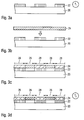
Die besonderen Verfahrensschritte bei der Herstellung des Sicherheitselements 12 der Fig. 2 werden nun anhand der Fig. 3 näher erläutert, wobei die Teilbilder jeweils Querschnitte durch das Sicherheitselement bei Zwischenschritten des Herstellungsverfahrens zeigen.The special process steps in the production of the
Mit Bezug auf Fig. 3(a) wird zunächst auf eine Trägerfolie 20, beispielsweise eine PET-Folie guter Oberflächenqualität, eine erste Schicht 22 aus nematischem flüssigkristallinem Material in Form des gewünschten Motivs aufgedruckt. Durch Beaufschlagen mit UV-Strahlung bei einer niedrigen Temperatur T1 wird die erste Schicht 22 nur unvollständig vernetzt. Die niedrige Temperatur T1 liegt dabei insbesondere unterhalb von 30 °C, im Ausführungsbeispiel bei 20 °C. Diese niedrige Temperatur kann beispielsweise dadurch erreicht werden, dass die Trägerfolie während der UV-Beaufschlagung über eine entsprechend eingestellte Kühlwalze geführt wird.With reference to FIG. 3 (a), a
Genauer gesagt wird die erste Schicht 22 in diesem Verfahrensschritt so stark vernetzt, dass sie tackfrei und wickelbar ist, die Vernetzung aber noch nicht vollständig erfolgt ist, um die im Folgenden beschriebene Wechselwirkung mit der anschließend aufgebrachten zweiten Schicht zu ermöglichen.More specifically, in this process step, the
In einem nächsten Schritt wird, wie in Fig. 3(b) illustriert, vollflächig eine zweite Schicht 24 aus einem cholesterischen flüssigkristallinen Material aufgedruckt. Entsprechend der Konzentration des eingesetzten Verdrillers zeigt die cholesterische zweite Schicht 24 im fertigen Sicherheitselement in den Schichtbereichen 26 ohne darunterliegende erste Schicht 22 einen Farbkippeffekt mit einer gewissen Auslegungswellenlänge des Reflexionsmaximums. Beispielsweise kann der Farbkippeffekt der unbeeinflussten zweiten Schicht 24 einen Farbeindruck zeigen, der sich beim Kippen des Sicherheitselements aus der Senkrechten heraus von Grün nach Blau ändert.In a next step, as illustrated in FIG. 3 (b), a
In den Schichtbereichen 28, in denen die Trägerfolie 20 bereits mit der teilweise vernetzten ersten Schicht 22 bedruckt ist, findet nun eine Wechselwirkung zwischen dem neu aufgebrachten cholesterischen Flüssigkristallmaterial und den darunterliegenden Nematen statt, die sich in einer Verschiebung des Reflexionsmaximums der zweiten Schicht 24 in den langwelligen Bereich zeigt. Beispielsweise weisen im fertigen Sicherheitselement die Schichtbereiche 28 nach erfolgter Wechselwirkung einen Farbkippeffekt auf, bei dem sich der Farbeindruck beim Kippen des Sicherheitselements aus der Senkrechten heraus von Rot nach Grün ändert. Diese unterschiedlichen Farbkippeffekte der zweiten Schicht 24 sind in Fig. 3(c) durch die unterschiedliche Schraffur der Schichtbereiche 26 und 28 angedeutet.In the
Ohne an eine bestimmte Erklärung gebunden zu sein, wird gegenwärtig vermutet, dass die langwellige Verschiebung des Reflexionsmaximums von einer Vermischung des aufgebrachten cholesterischen Flüssigkristallmaterials mit dem noch nicht vollständig vernetzten nematischen Flüssigkristallmaterial während des Druckvorgangs herrührt. Durch die niedrige Polymerisationstemperatur T1 bleibt der Vernetzungsgrad der Nematenschicht 22 zunächst so niedrig, dass beim Druck der zweiten cholesterischen Schicht 24 ein Anlösen der ersten Schicht 22 erfolgt.Without wishing to be bound by any particular explanation, it is presently believed that the long wavelength shift of the reflection maximum is due to a mixing of the applied cholesteric liquid crystal material with the not yet fully crosslinked nematic liquid crystal material during the printing process. Due to the low polymerization temperature T 1 , the degree of crosslinking of the
In den Schichtbereichen 28 sinkt durch die Mischung des aufgedruckten cholesterischen Flüssigkristallmaterials mit den nematischen Flüssigkristallen die Konzentration des Verdrillers in der zweiten Schicht 24. Die Pitchhöhe nimmt dadurch zu und das Reflexionsmaximum wird entsprechend ins Langwellige verschoben. In den Schichtbereichen 26 ohne darunterliegende erste Schicht 24 findet keine Wechselwirkung und damit auch keine Verschiebung des Reflexionsmaximums statt, dort wird vielmehr ein Farbkippeffekt entsprechend der Auslegung der cholesterischen Schicht 24 beobachtet.In the
Zurückkommend auf die Darstellung der Fig. 3 werden die erste und zweite Schicht 22, 24 nunmehr durch UV-Beaufschlagung bei einer höheren Temperatur T2 vollständig vernetzt, was in Fig. 3(d) durch die Kreuzschraffur angedeutet ist. Vorzugsweise erfolgt die Vernetzung bei einer Temperatur T2 oberhalb von 50 °C. Die beiden unterschiedlichen Farbkippeffekte in den Schichtbereichen 26 und 28 der zweiten Schicht 24 werden dadurch dauerhaft fixiert.Returning to the illustration of FIG. 3, the first and
Weitere Verfahrensschritte zur Herstellung des Sicherheitselements 12 schließen sich in herkömmlicher Weise an. Beispielsweise kann die Schichtenfolge der Fig. 3(d) noch mit einem Kaschierkleber beschichtet und auf ein gewünschtes Zielsubstrat übertragen werden. Je nach Anwendung kann die Trägerfolie 20 entfernt werden oder auch einen Teil des fertigen Sicherheitselements bilden.Further method steps for producing the
Die erreichbare Kantenschärfe der unterschiedlichen nebeneinanderliegenden Farbkippeffekte der Schichtbereiche 26 und 28 ist in der vorliegenden Erfindung im Wesentlichen nur durch die erreichbare hohe Kantenschärfe der aufgedruckten Nematenschicht 22 bestimmt. Die unterschiedlichen farbkippenden Motivbereiche 26, 28 können daher ebenfalls eine sehr hohe Kantenschärfe aufweisen.The achievable edge sharpness of the different adjacent color shift effects of the
Je nach der Menge der nur unvollständig vernetzten Nematen 22 kann die cholesterische Schicht 24 von diesen mehr oder weniger stark beeinflusst werden. Wird die cholesterische Schicht 24 beispielsweise für einen Farbkippeffekt von Blau nach Ultraviolett ausgelegt, können durch unterschiedliche Schichtdicken der Nematenschicht 22 verschieden starke Farbverschiebungen ins Langwellige erreicht werden, im Extremfall bis hin zu einem Farbkippeffekt von Infrarot nach Rot. Die verschiedenen Farbkippeffekte können dabei in einem Sicherheitselement mit einer einzigen cholesterischen Schicht 24 verwirklicht werden.Depending on the amount of only incompletely crosslinked
Die erfindungsgemäße Wechselwirkung der beiden Schichten ist unerwartet, da die erste Schicht nach der unvollständigen Vernetzung bereits tackfrei und daher wickelbar ist. Der Effekt kann beispielsweise auch in den Fällen vorteilhaft ausgenutzt werden, in denen keine Möglichkeit besteht, Nass-in-Nass zu drucken. Da die aufgedruckten Flüssigkristallschichten jeweils eine gewisse Alignmentstrecke benötigen, ist es schwierig, eine Druckmaschine mit mehreren aufeinanderfolgenden Druckwerken und ausreichend langen Alignmentstrecken zu finden.The interaction of the two layers according to the invention is unexpected since the first layer after the incomplete crosslinking is already tack-free and therefore windable. The effect can, for example, also be used to advantage in cases where there is no possibility of printing wet-on-wet. Since the printed liquid crystal layers each require a certain alignment distance, it is difficult to find a printing press with several successive printing units and sufficiently long alignment distances.
Darüber hinaus bietet das erfindungsgemäße Verfahren eine große Freiheit bei der Wahl der Druckverfahren, da die erste und zweite Schicht wegen der Wickelbarkeit der ersten Schicht mit unterschiedlichen Druckverfahren und sogar auf unterschiedlichen Druckmaschinen erzeugt werden können.In addition, the method according to the invention offers great freedom in the choice of the printing methods, since the first and second layers can be produced with different printing methods and even on different printing machines because of the windability of the first layer.
Ein weiteres Ausführungsbeispiel der Erfindung wird nun anhand der Figuren 4 und 5 erläutert. Das Sicherheitselement 30 der Fig. 4 weist ein offenes erstes Motiv 32 auf, das durch Bereiche 34 und 36 mit unterschiedlichem Farbkippeffekt gebildet ist, wie in Fig. 4(a) gezeigt. Darüber hinaus enthält das Sicherheitselement 30 ein verstecktes zweites Motiv 38, das bei Betrachtung mit bloßem Auge praktisch nicht erkennbar ist und erst bei Betrachtung mit einem Polarisator 40 deutlich in Erscheinung tritt, wie in Fig. 4(b) dargestellt.A further embodiment of the invention will now be explained with reference to Figures 4 and 5. The
Zwischenschritte bei der erfindungsgemäßen Herstellung des Sicherheitselements 30 sind in den Teilbildern der Fig. 5 veranschaulicht. Bezug nehmend auf die Fig. 5(a) wird zunächst eine dritte Schicht 42 aus einem nematischen flüssigkristallinen Material in Form des gewünschten versteckten Motivs, hier des Wappenmotivs der Fig. 4(b), auf eine Trägerfolie 20 aufgedruckt und durch Beaufschlagung mit UV-Strahlung bei einer hohen Temperatur T2 vollständig vernetzt.Intermediate steps in the production of the
Diese dritte Schicht 42, die der Erzeugung des versteckten Motivs dient, wird in einer variierenden Schichtdicke aufgebracht, die einen guten Motivkontrast im Polarisator sicherstellt. Anstelle der in Fig. 5(a) gezeigten Dickenvariation zwischen einer Schichtdicke d und der Schichtdicke Null können für die dritte Schicht 42 selbstverständlich auch Dickenvariation zwischen einer ersten und einer zweiten Schichtdicke d1 bzw. d2, oder zwischen mehr als zwei verschiedenen Schichtdicken zum Einsatz kommen.This
Wie in Fig. 5(b) dargestellt, wird auf die dritte Schicht 42 eine erste Schicht 22 aus nematischem flüssigkristallinem Material in Form des gewünschten offenen Motivs aufgedruckt. Die erste Schicht 22 wird wie beim Ausführungsbeispiel der Fig. 3 durch Beaufschlagung mit UV-Strahlung bei einer niedrigen Temperatur T1 nur unvollständig vernetzt. In der Regel wird die erste Schicht 22 dünner als die dritte Schicht 42 ausgebildet, so dass sie im fertigen Sicherheitselement eine geringere Wirkung auf die Polarisation des durchtretenden Lichts ausübt.As shown in Fig. 5 (b), a
Im nächsten Schritt wird dann vollflächig eine zweite Schicht 24 aus einem cholesterischen flüssigkristallinen Material aufgedruckt. Wie bereits bei Fig. 3(c) beschrieben, entstehen durch die Wechselwirkung der cholesterischen Schicht 24 mit der darunterliegenden, unvollständig vernetzten Nematenschicht 22 zwei Schichtbereiche 26, 28 mit unterschiedlichem Farbkippeffekt, wobei die Schichtbereiche 26 und 28 zusammen das offene Motiv bilden. Diese entstandene Situation ist in Fig. 5(c) schematisch dargestellt. Eine entsprechende Wechselwirkung der cholesterischen Schicht 24 mit der dritten Schicht 42 kann nicht stattfinden, da die dritte Schicht 42 beim Aufbringen der zweiten Schicht 24 bereits vollständig ausgehärtet ist und daher, anders als die erste Schicht 22, beim Druck nicht angelöst wird.In the next step, a
Nachfolgend werden die erste und zweite Schicht 22, 24 durch UV-Beaufschlagung bei einer höheren Temperatur T2 vollständig vernetzt, wie in Fig. 5(d) dargestellt, um die unterschiedlichen Farbkippeffekte des ersten Motivs 26, 28 dauerhaft zu fixieren. Weitere an sich bekannte Verfahrensschritte zur Fertigstellung des Sicherheitselements können sich anschließen.Subsequently, the first and
Fig. 6 illustriert eine weitere erfindungsgemäße Möglichkeit, den Farbkippeffekt cholesterischer Flüssigkristallschichten nachträglich gezielt zu beeinflussen:FIG. 6 illustrates a further possibility according to the invention for subsequently selectively influencing the color-shift effect of cholesteric liquid-crystal layers:
Wird auf die Schichtenfolge der Fig. 3(d) für die Weiterverarbeitung eine vollflächige Schicht eines Kaschierklebers 50 aufgebracht, wie in Fig. 6(a) dargestellt, so bleibt das Farbspiel der Schichtbereiche 26, 28 davon unbeeinflusst, da die vollständige Aushärtung der cholesterischen Schicht 24 deren Farbkippeffekte bereits fixiert hat.If a full-surface layer of a
Wird der Kaschierkleber andererseits, wie in Fig. 6(b) dargestellt, bereits vor der vollständigen Aushärtung der ersten und zweiten Schicht 22, 24 aufgebracht, so wird eine Verschiebung der Farbkippeffekte der Schichtbereiche 26, 28 ins Kurzwellige beobachtet, was in der Darstellung der Fig. 6(c) durch die engere Schraffur angedeutet ist. Diese kurzwellige Verschiebung der Farbkippeffekte wird nachfolgend durch Vernetzen bei der höheren Temperatur T2 fixiert, wie in Fig. 6(d) dargestellt. Gegenüber der Ausgestaltung der Fig. 6(a) zeigt das Sicherheitselement der Fig. 6(d) somit das erste Motiv mit gemeinsam ins Kurzwellige verschobenen Farbkippeffekten in den Bereichen 26, 28.On the other hand, if the laminating adhesive, as shown in FIG. 6 (b), is already applied before the complete curing of the first and
Die kurzwellige Verschiebung der Farbkippeffekte kann auch durch das Aufbringen eines anderen lösungsmittelhaltigen Beschichtungsstoffes, beispielsweise eines lösungsmittelhaltigen Lacks erreicht werden. Dabei kann der lösungsmittelhaltige Beschichtungsstoff insbesondere auch in Form eines weiteren Motivs aufgebracht werden, um eine lokal unterschiedliche Änderung der Farbkippeffekte zu erzielen.The short-wave shift of the color shift effects can also be achieved by the application of another solvent-containing coating material, for example a solvent-containing paint. In this case, the solvent-containing coating material can in particular also be applied in the form of a further motif in order to achieve a locally different change in the color-shift effects.
Diese kurzwellige Verschiebung kann auch mit der oben beschriebenen langwelligen Verschiebung durch eine unvollständig vernetzte Nematenschicht kombiniert werden, so dass durch einfache Maßnahmen eine Vielzahl unterschiedlicher Farbkippeffekte in einem einzigen Sicherheitselement verwirklicht werden kann, wie nachfolgend anhand der Darstellung der Fig. 7 illustriert.This short-wave displacement can also be combined with the above-described long-wave displacement by an incompletely crosslinked Nematenschicht, so that a plurality of different color shift effects can be realized in a single security element by simple measures, as illustrated below with reference to the illustration of FIG. 7.
Fig. 7 zeigt einen beispielhaften Aufbau eines Sicherheitsfadens 60, bei dem die Schichtenfolge der Flüssigkristallschichten bereits auf einen Fadengrundaufbau 62 übertragen und die für die Herstellung eingesetzte Trägerfolie abgelöst wurde. Die Reihenfolge der gezeigten Flüssigkristallschichten ist daher gegenüber den Darstellungen der Figuren 3, 5 und 6 invertiert.FIG. 7 shows an exemplary construction of a
Von oben nach unten gesehen weist der Sicherheitsfaden 60 eine dritte Schicht 42 aus einem nematischen flüssigkristallinen Material in Form eines gewünschten zweiten (versteckten) Motivs, eine erste Schicht 22 aus einem nematischen flüssigkristallinen Material in Form eines gewünschten ersten (offenen) Motivs, eine vollflächig aufgebrachte zweite Schicht 24 aus einem cholesterischen flüssigkristallinen Material, eine in Form eines gewünschten dritten (offenen) Motivs aufgebrachte lösungsmittelhaltige Lackschicht 52, eine vollflächig aufgebrachte Lackschicht 54, eine Kaschierkleberschicht 56 und einen Fadengrundaufbau 62 auf.Viewed from top to bottom, the
Der Fadengrundaufbau 62 folgt an sich bekannten Gestaltungen und kann beispielsweise eine Metallisierung mit Negativschrift, eine Rastermetallisierung, eine schwarze Beschichtung mit Negativschrift und/oder magnetische Schichtbereiche enthalten.The
Diese dritte Schicht 42 wurde bei der Herstellung des Sicherheitsfadens 62. nach dem Aufbringen bei einer höheren Temperatur vollständig vernetzt, wie im Zusammenhang mit Fig. 5 beschrieben. Die erste Schicht 22 wurde nach dem Aufbringen zunächst bei einer niedrigen Temperatur nur unvollständig vernetzt. Auf diese unvollständig vernetzte erste Schicht wurde vollflächig die zweite Schicht 24 aufgedruckt und auch die zweite Schicht 24 zunächst bei einer niedrigen Temperatur nur unvollständig vernetzt. Dann wurde die lösungsmittelhaltige Lackschicht 52 auf die unvollständig vernetzte zweite Schicht 24 aufgebracht.This
Die cholesterische zweite Schicht 24 wird bei dem Ausführungsbeispiel der Fig. 7 daher zweifach beeinflusst: Zum einen durch die Wechselwirkung mit der unvollständig vernetzten Nematenschicht 22, die zu einer lokalen Verschiebung des Farbkippeffekts ins Langwellige führt, zum anderen durch die Wechselwirkung mit der lösungsmittelhaltigen Lackschicht, die zu einer lokalen Verschiebung des Farbkippeffekts der unvollständig vernetzten cholesterischen Schicht 24 ins Kurzwellige führt.The cholesteric
Erst nach dem Aufbringen der lösungsmittelhaltigen Lackschicht 52 wurden die erste und zweite Schicht 22, 24 durch UV-Beaufschlagung bei höherer Temperatur vollständig vernetzt und die vorher induzierten lokalen Änderungen der farbkippenden Eigenschaften der cholesterischen Schicht fixiert. Das nachfolgende Aufbringen der weiteren Lackschicht 54, der Kaschierkleberschicht 56 und das Übertragen der Schichtenfolge auf den Fadengrundaufbau 62 haben dann keinen Einfluss mehr auf das Erscheinungsbild der Farbkippeffekte.Only after the application of the solvent-containing lacquer layer 52 were the first and
Insgesamt entstehen auf diese Weise in dem Sicherheitsfaden 60 acht Bereiche B1 bis B8 mit unterschiedlichem Erscheinungsbild, wie in Fig. 7 gezeigt. Im ersten Bereich B1 ist der unbeeinflusste Farbkippeffekt der cholesterischen Schicht 24 zu erkennen. Im zweiten Bereich B2 erscheint der Farbkippeffekt der cholesterischen Schicht 24 durch die Wechselwirkung mit der ersten Schicht 22 ins Langwellige verschoben, wie in Zusammenhang mit Fig. 3 erläutert.Overall, in this way in the
Im dritten Bereich B3 ist der Farbkippeffekt der cholesterischen Schicht 24 durch die Wechselwirkung mit der lösungsmittelhaltigen Lackschicht 52 ins Kurzwellige verschoben, wie bei Fig. 6 erläutert. Im Bereich B4 überlagern sich die kurzwellige und die langwellige Verschiebung zu einer effektiven Gesamt-Farbverschiebung, die von den relativen Größen der beiden Komponenten abhängt.In the third region B 3 , the color-shift effect of the
Es versteht sich, dass das Ausmaß der Verschiebung ins Langwellige der Bereich B2 und B4, und das Ausmaß der Verschiebung ins Kurzwellige der Bereich B3 und B4 jeweils durch die Schichtdicke der ersten Schicht 22 bzw. der lösungsmittelhaltigen Lackschicht 52 eingestellt werden kann. Die Schichten 22 und 52 können in Unterbereichen auch verschiedene Dicke aufweisen, so dass verschieden starke Verschiebungen in einem einzigen Sicherheitselement realisiert werden können.It is understood that the extent of the shift to the long-wave region B 2 and B 4 , and the extent of the shift to the short-wave region B 3 and B 4 can be adjusted in each case by the layer thickness of the
Die Bereiche B5 bis B8 unterscheiden sich von den Bereichen B1 bis B4 nur dadurch, dass sie auf der dritten Schicht 42 aufgebracht sind. Sie zeigen daher bei Betrachtung ohne Hilfsmittel dasselbe Erscheinungsbild wie die Bereiche B1 bis B4, heben sich aber bei Betrachtung im Polarisator von diesen deutlich ab, wie bereits bei der Beschreibung der Fig. 4 erläutert.The areas B 5 to B 8 differ from the areas B 1 to B 4 only in that they are applied to the
Insgesamt eröffnet die Erfindung dem Designer eine Vielzahl an Möglichkeiten, scharf begrenzte offene und versteckte Motive mit unterschiedlichen Farbkippeffekten in einem einzigen Sicherheitselement zu kombinieren.Overall, the invention provides the designer with a variety of ways to combine sharply defined open and hidden motifs with different color shift effects in a single security element.
Claims (34)
Applications Claiming Priority (1)
| Application Number | Priority Date | Filing Date | Title |
|---|---|---|---|
| DE102006040227A DE102006040227A1 (en) | 2006-08-28 | 2006-08-28 | Security element with color-shifting motif layer |
Publications (3)
| Publication Number | Publication Date |
|---|---|
| EP1894736A2 true EP1894736A2 (en) | 2008-03-05 |
| EP1894736A3 EP1894736A3 (en) | 2014-05-21 |
| EP1894736B1 EP1894736B1 (en) | 2017-06-21 |
Family
ID=38566159
Family Applications (1)
| Application Number | Title | Priority Date | Filing Date |
|---|---|---|---|
| EP07016548.5A Active EP1894736B1 (en) | 2006-08-28 | 2007-08-23 | Security element with a color-shift effect and method for producing said security element |
Country Status (2)
| Country | Link |
|---|---|
| EP (1) | EP1894736B1 (en) |
| DE (1) | DE102006040227A1 (en) |
Cited By (12)
| Publication number | Priority date | Publication date | Assignee | Title |
|---|---|---|---|---|
| EP2073986A1 (en) * | 2006-10-10 | 2009-07-01 | De La Rue International Limited | Improvements in security devices |
| WO2009121605A2 (en) * | 2008-04-02 | 2009-10-08 | Sicpa Holding S.A. | Identification and authentication using liquid crystal material markings |
| EP2144731A1 (en) * | 2007-05-09 | 2010-01-20 | LEONHARD KURZ Stiftung & Co. KG | Film element having a polymer layer |
| DE102008061608A1 (en) | 2008-12-11 | 2010-06-17 | Giesecke & Devrient Gmbh | security element |
| WO2011098626A1 (en) | 2009-12-01 | 2011-08-18 | Universidad Politécnica de Madrid | Document security method and device involving the generation of multiple images |
| WO2011120620A1 (en) | 2010-03-30 | 2011-10-06 | Merck Patent Gmbh | Method for producing multicoloured coatings |
| US8734678B2 (en) | 2009-04-02 | 2014-05-27 | Sicpa Holding Sa | Identification and authentication using polymeric liquid crystal material markings |
| AT516128A1 (en) * | 2014-07-17 | 2016-02-15 | Hueck Folien Gmbh | Security element with color shift effect and tamper evidence |
| EP3392054A1 (en) | 2017-04-19 | 2018-10-24 | Giesecke+Devrient Currency Technology GmbH | Polymeric valuable document substrate, security element, valuable document and method of manufacturing |
| EP3466711A1 (en) | 2017-10-05 | 2019-04-10 | Giesecke+Devrient Currency Technology GmbH | Two-sided transparent window feature with dichroic dyes |
| CN110853112A (en) * | 2019-11-11 | 2020-02-28 | 燕山大学 | Three-dimensional chiral nano anti-counterfeiting device and pattern manufacturing method |
| CN115210083A (en) * | 2019-12-20 | 2022-10-18 | 奥贝蒂尔信托简易股份公司 | Optical structure with relief effect |
Families Citing this family (1)
| Publication number | Priority date | Publication date | Assignee | Title |
|---|---|---|---|---|
| WO2008044291A1 (en) * | 2006-10-11 | 2008-04-17 | Mikio Takeji | Tape cutter |
Citations (2)
| Publication number | Priority date | Publication date | Assignee | Title |
|---|---|---|---|---|
| DE102004021246A1 (en) * | 2004-04-30 | 2005-11-24 | Giesecke & Devrient Gmbh | Security element and method for its production |
| DE102004053008A1 (en) * | 2004-10-29 | 2006-05-04 | Giesecke & Devrient Gmbh | Production of a film material for security elements comprises preparing a plastic carrier film suitable for aligning liquid crystalline material and partially applying a first layer of liquid crystalline material on the carrier film |
-
2006
- 2006-08-28 DE DE102006040227A patent/DE102006040227A1/en not_active Withdrawn
-
2007
- 2007-08-23 EP EP07016548.5A patent/EP1894736B1/en active Active
Patent Citations (2)
| Publication number | Priority date | Publication date | Assignee | Title |
|---|---|---|---|---|
| DE102004021246A1 (en) * | 2004-04-30 | 2005-11-24 | Giesecke & Devrient Gmbh | Security element and method for its production |
| DE102004053008A1 (en) * | 2004-10-29 | 2006-05-04 | Giesecke & Devrient Gmbh | Production of a film material for security elements comprises preparing a plastic carrier film suitable for aligning liquid crystalline material and partially applying a first layer of liquid crystalline material on the carrier film |
Cited By (25)
| Publication number | Priority date | Publication date | Assignee | Title |
|---|---|---|---|---|
| EP2073986A1 (en) * | 2006-10-10 | 2009-07-01 | De La Rue International Limited | Improvements in security devices |
| EP2073986B1 (en) * | 2006-10-10 | 2012-08-29 | De La Rue International Limited | Improvements in security devices |
| GB2442711B (en) * | 2006-10-10 | 2011-04-13 | Rue De Int Ltd | Improvements in security devices |
| EP2144731A1 (en) * | 2007-05-09 | 2010-01-20 | LEONHARD KURZ Stiftung & Co. KG | Film element having a polymer layer |
| EP2144731B1 (en) * | 2007-05-09 | 2012-03-21 | Leonhard Kurz Stiftung & Co. KG | Film element having a polymer layer |
| US8734679B2 (en) | 2008-04-02 | 2014-05-27 | Sicpa Holding Sa | Identification and authentication using liquid crystal material markings |
| WO2009121605A2 (en) * | 2008-04-02 | 2009-10-08 | Sicpa Holding S.A. | Identification and authentication using liquid crystal material markings |
| US8740088B2 (en) | 2008-04-02 | 2014-06-03 | Sicpa Holding Sa | Identification and authentication using liquid crystal material markings |
| EA022590B1 (en) * | 2008-04-02 | 2016-01-29 | Сикпа Холдинг Са | Identification and authentication using liquid crystal material markings |
| DE102008061608A1 (en) | 2008-12-11 | 2010-06-17 | Giesecke & Devrient Gmbh | security element |
| EP2196322B1 (en) | 2008-12-11 | 2017-10-25 | Giesecke+Devrient Currency Technology GmbH | Security element |
| US8734678B2 (en) | 2009-04-02 | 2014-05-27 | Sicpa Holding Sa | Identification and authentication using polymeric liquid crystal material markings |
| US9200204B2 (en) | 2009-04-02 | 2015-12-01 | Sicpa Holding Sa | Identification and authentication using polymeric liquid crystal material markings |
| WO2011098626A1 (en) | 2009-12-01 | 2011-08-18 | Universidad Politécnica de Madrid | Document security method and device involving the generation of multiple images |
| US8885121B2 (en) | 2009-12-01 | 2014-11-11 | Universidad Politecnica De Madrid | Procedure and device of documental security based on generation of multiple images |
| WO2011120620A1 (en) | 2010-03-30 | 2011-10-06 | Merck Patent Gmbh | Method for producing multicoloured coatings |
| AT516128A1 (en) * | 2014-07-17 | 2016-02-15 | Hueck Folien Gmbh | Security element with color shift effect and tamper evidence |
| AT516128B1 (en) * | 2014-07-17 | 2018-05-15 | Hueck Folien Gmbh | Security element with color shift effect and tamper evidence |
| EP3392054A1 (en) | 2017-04-19 | 2018-10-24 | Giesecke+Devrient Currency Technology GmbH | Polymeric valuable document substrate, security element, valuable document and method of manufacturing |
| DE102017003795A1 (en) | 2017-04-19 | 2018-10-25 | Giesecke+Devrient Currency Technology Gmbh | Polymeric value document substrate, security element, value document and manufacturing method |
| EP3466711A1 (en) | 2017-10-05 | 2019-04-10 | Giesecke+Devrient Currency Technology GmbH | Two-sided transparent window feature with dichroic dyes |
| WO2019068655A1 (en) | 2017-10-05 | 2019-04-11 | Giesecke+Devrient Currency Technology Gmbh | Two-sided transparent window feature with dichroic dyes |
| CN110853112A (en) * | 2019-11-11 | 2020-02-28 | 燕山大学 | Three-dimensional chiral nano anti-counterfeiting device and pattern manufacturing method |
| CN115210083A (en) * | 2019-12-20 | 2022-10-18 | 奥贝蒂尔信托简易股份公司 | Optical structure with relief effect |
| US20230356541A1 (en) * | 2019-12-20 | 2023-11-09 | Oberthur Fiduciaire Sas | Optical Structure Having a Relief Effect |
Also Published As
| Publication number | Publication date |
|---|---|
| EP1894736B1 (en) | 2017-06-21 |
| DE102006040227A1 (en) | 2008-03-06 |
| EP1894736A3 (en) | 2014-05-21 |
Similar Documents
| Publication | Publication Date | Title |
|---|---|---|
| EP1894736B1 (en) | Security element with a color-shift effect and method for producing said security element | |
| EP1744903B2 (en) | Security element and method for producing same | |
| EP1744902B1 (en) | Security element and process for producing the same | |
| EP1724619B1 (en) | Film and optical fuse element | |
| EP2465701B1 (en) | Security element with identification marks | |
| DE102004046695A1 (en) | Optically variable security element | |
| EP2225107B1 (en) | Security element, and method for the production thereof | |
| EP1744901A1 (en) | Security element and method for producing said element | |
| WO2008138539A1 (en) | Film element having a polymer layer | |
| EP2033026A2 (en) | Security element | |
| EP2196322B1 (en) | Security element | |
| EP3284612A1 (en) | Optically variable security element with a thin film element | |
| EP2261053B1 (en) | Security element having a motif producing liquid crystal layer | |
| EP2094502B1 (en) | Security feature comprising liquid crystal layers | |
| EP4037913B1 (en) | Method for producing a security paper and security paper obtainable by said method | |
| EP4217205A1 (en) | Optically variable security element having a reflective surface region | |
| EP3403844B1 (en) | Method for producing a security element having a metallized relief area | |
| EP1491357A2 (en) | Printing substrate having an optically anisotropic layer |
Legal Events
| Date | Code | Title | Description |
|---|---|---|---|
| PUAI | Public reference made under article 153(3) epc to a published international application that has entered the european phase |
Free format text: ORIGINAL CODE: 0009012 |
|
| AK | Designated contracting states |
Kind code of ref document: A2 Designated state(s): AT BE BG CH CY CZ DE DK EE ES FI FR GB GR HU IE IS IT LI LT LU LV MC MT NL PL PT RO SE SI SK TR |
|
| AX | Request for extension of the european patent |
Extension state: AL BA HR MK YU |
|
| PUAL | Search report despatched |
Free format text: ORIGINAL CODE: 0009013 |
|
| AK | Designated contracting states |
Kind code of ref document: A3 Designated state(s): AT BE BG CH CY CZ DE DK EE ES FI FR GB GR HU IE IS IT LI LT LU LV MC MT NL PL PT RO SE SI SK TR |
|
| AX | Request for extension of the european patent |
Extension state: AL BA HR MK RS |
|
| RIC1 | Information provided on ipc code assigned before grant |
Ipc: B41M 3/14 20060101AFI20140423BHEP Ipc: B42D 25/29 20140101ALI20140423BHEP Ipc: B42D 15/00 20060101ALI20140423BHEP Ipc: C09K 19/02 20060101ALI20140423BHEP Ipc: B42D 25/00 20140101ALI20140423BHEP |
|
| 17P | Request for examination filed |
Effective date: 20141023 |
|
| RBV | Designated contracting states (corrected) |
Designated state(s): AT BE BG CH CY CZ DE DK EE ES FI FR GB GR HU IE IS IT LI LT LU LV MC MT NL PL PT RO SE SI SK TR |
|
| AKX | Designation fees paid |
Designated state(s): AT BE BG CH CY CZ DE DK EE ES FI FR GB GR HU IE IS IT LI LT LU LV MC MT NL PL PT RO SE SI SK TR |
|
| AXX | Extension fees paid |
Extension state: RS Extension state: AL Extension state: MK Extension state: HR Extension state: BA |
|
| 17Q | First examination report despatched |
Effective date: 20160210 |
|
| RIC1 | Information provided on ipc code assigned before grant |
Ipc: B42D 25/00 20140101ALI20161031BHEP Ipc: B41M 3/14 20060101AFI20161031BHEP Ipc: C09K 19/02 20060101ALI20161031BHEP |
|
| GRAP | Despatch of communication of intention to grant a patent |
Free format text: ORIGINAL CODE: EPIDOSNIGR1 |
|
| INTG | Intention to grant announced |
Effective date: 20161215 |
|
| GRAS | Grant fee paid |
Free format text: ORIGINAL CODE: EPIDOSNIGR3 |
|
| GRAJ | Information related to disapproval of communication of intention to grant by the applicant or resumption of examination proceedings by the epo deleted |
Free format text: ORIGINAL CODE: EPIDOSDIGR1 |
|
| GRAL | Information related to payment of fee for publishing/printing deleted |
Free format text: ORIGINAL CODE: EPIDOSDIGR3 |
|
| INTC | Intention to grant announced (deleted) | ||
| GRAR | Information related to intention to grant a patent recorded |
Free format text: ORIGINAL CODE: EPIDOSNIGR71 |
|
| GRAA | (expected) grant |
Free format text: ORIGINAL CODE: 0009210 |
|
| AK | Designated contracting states |
Kind code of ref document: B1 Designated state(s): AT BE BG CH CY CZ DE DK EE ES FI FR GB GR HU IE IS IT LI LT LU LV MC MT NL PL PT RO SE SI SK TR |
|
| INTG | Intention to grant announced |
Effective date: 20170512 |
|
| REG | Reference to a national code |
Ref country code: GB Ref legal event code: FG4D Free format text: NOT ENGLISH |
|
| REG | Reference to a national code |
Ref country code: CH Ref legal event code: EP |
|
| REG | Reference to a national code |
Ref country code: IE Ref legal event code: FG4D Free format text: LANGUAGE OF EP DOCUMENT: GERMAN |
|
| REG | Reference to a national code |
Ref country code: AT Ref legal event code: REF Ref document number: 902578 Country of ref document: AT Kind code of ref document: T Effective date: 20170715 |
|
| REG | Reference to a national code |
Ref country code: CH Ref legal event code: NV Representative=s name: RENTSCH PARTNER AG, CH |
|
| REG | Reference to a national code |
Ref country code: DE Ref legal event code: R096 Ref document number: 502007015711 Country of ref document: DE |
|
| REG | Reference to a national code |
Ref country code: DE Ref legal event code: R081 Ref document number: 502007015711 Country of ref document: DE Owner name: GIESECKE+DEVRIENT CURRENCY TECHNOLOGY GMBH, DE Free format text: FORMER OWNER: GIESECKE DEVRIENT GMBH, 81677 MUENCHEN, DE Ref country code: DE Ref legal event code: R081 Ref document number: 502007015711 Country of ref document: DE Owner name: GIESECKE+DEVRIENT CURRENCY TECHNOLOGY GMBH, DE Free format text: FORMER OWNER: GIESECKE & DEVRIENT GMBH, 81677 MUENCHEN, DE |
|
| REG | Reference to a national code |
Ref country code: FR Ref legal event code: PLFP Year of fee payment: 11 |
|
| REG | Reference to a national code |
Ref country code: CH Ref legal event code: PCAR Free format text: NEW ADDRESS: BELLERIVESTRASSE 203 POSTFACH, 8034 ZUERICH (CH) |
|
| REG | Reference to a national code |
Ref country code: NL Ref legal event code: MP Effective date: 20170621 |
|
| PG25 | Lapsed in a contracting state [announced via postgrant information from national office to epo] |
Ref country code: GR Free format text: LAPSE BECAUSE OF FAILURE TO SUBMIT A TRANSLATION OF THE DESCRIPTION OR TO PAY THE FEE WITHIN THE PRESCRIBED TIME-LIMIT Effective date: 20170922 Ref country code: LT Free format text: LAPSE BECAUSE OF FAILURE TO SUBMIT A TRANSLATION OF THE DESCRIPTION OR TO PAY THE FEE WITHIN THE PRESCRIBED TIME-LIMIT Effective date: 20170621 Ref country code: FI Free format text: LAPSE BECAUSE OF FAILURE TO SUBMIT A TRANSLATION OF THE DESCRIPTION OR TO PAY THE FEE WITHIN THE PRESCRIBED TIME-LIMIT Effective date: 20170621 |
|
| REG | Reference to a national code |
Ref country code: LT Ref legal event code: MG4D |
|
| PG25 | Lapsed in a contracting state [announced via postgrant information from national office to epo] |
Ref country code: SE Free format text: LAPSE BECAUSE OF FAILURE TO SUBMIT A TRANSLATION OF THE DESCRIPTION OR TO PAY THE FEE WITHIN THE PRESCRIBED TIME-LIMIT Effective date: 20170621 Ref country code: LV Free format text: LAPSE BECAUSE OF FAILURE TO SUBMIT A TRANSLATION OF THE DESCRIPTION OR TO PAY THE FEE WITHIN THE PRESCRIBED TIME-LIMIT Effective date: 20170621 Ref country code: BG Free format text: LAPSE BECAUSE OF FAILURE TO SUBMIT A TRANSLATION OF THE DESCRIPTION OR TO PAY THE FEE WITHIN THE PRESCRIBED TIME-LIMIT Effective date: 20170921 Ref country code: NL Free format text: LAPSE BECAUSE OF FAILURE TO SUBMIT A TRANSLATION OF THE DESCRIPTION OR TO PAY THE FEE WITHIN THE PRESCRIBED TIME-LIMIT Effective date: 20170621 |
|
| REG | Reference to a national code |
Ref country code: CH Ref legal event code: PUE Owner name: GIESECKE+DEVRIENT CURRENCY TECHNOLOGY GMBH, DE Free format text: FORMER OWNER: GIESECKE AND DEVRIENT GMBH, DE |
|
| PG25 | Lapsed in a contracting state [announced via postgrant information from national office to epo] |
Ref country code: RO Free format text: LAPSE BECAUSE OF FAILURE TO SUBMIT A TRANSLATION OF THE DESCRIPTION OR TO PAY THE FEE WITHIN THE PRESCRIBED TIME-LIMIT Effective date: 20170621 Ref country code: EE Free format text: LAPSE BECAUSE OF FAILURE TO SUBMIT A TRANSLATION OF THE DESCRIPTION OR TO PAY THE FEE WITHIN THE PRESCRIBED TIME-LIMIT Effective date: 20170621 Ref country code: CZ Free format text: LAPSE BECAUSE OF FAILURE TO SUBMIT A TRANSLATION OF THE DESCRIPTION OR TO PAY THE FEE WITHIN THE PRESCRIBED TIME-LIMIT Effective date: 20170621 Ref country code: SK Free format text: LAPSE BECAUSE OF FAILURE TO SUBMIT A TRANSLATION OF THE DESCRIPTION OR TO PAY THE FEE WITHIN THE PRESCRIBED TIME-LIMIT Effective date: 20170621 |
|
| REG | Reference to a national code |
Ref country code: GB Ref legal event code: 732E Free format text: REGISTERED BETWEEN 20180118 AND 20180124 |
|
| PG25 | Lapsed in a contracting state [announced via postgrant information from national office to epo] |
Ref country code: ES Free format text: LAPSE BECAUSE OF FAILURE TO SUBMIT A TRANSLATION OF THE DESCRIPTION OR TO PAY THE FEE WITHIN THE PRESCRIBED TIME-LIMIT Effective date: 20170621 Ref country code: IS Free format text: LAPSE BECAUSE OF FAILURE TO SUBMIT A TRANSLATION OF THE DESCRIPTION OR TO PAY THE FEE WITHIN THE PRESCRIBED TIME-LIMIT Effective date: 20171021 Ref country code: PL Free format text: LAPSE BECAUSE OF FAILURE TO SUBMIT A TRANSLATION OF THE DESCRIPTION OR TO PAY THE FEE WITHIN THE PRESCRIBED TIME-LIMIT Effective date: 20170621 |
|
| RAP2 | Party data changed (patent owner data changed or rights of a patent transferred) |
Owner name: GIESECKE+DEVRIENT CURRENCY TECHNOLOGY GMBH |
|
| REG | Reference to a national code |
Ref country code: DE Ref legal event code: R097 Ref document number: 502007015711 Country of ref document: DE |
|
| PG25 | Lapsed in a contracting state [announced via postgrant information from national office to epo] |
Ref country code: MC Free format text: LAPSE BECAUSE OF FAILURE TO SUBMIT A TRANSLATION OF THE DESCRIPTION OR TO PAY THE FEE WITHIN THE PRESCRIBED TIME-LIMIT Effective date: 20170621 |
|
| PLBE | No opposition filed within time limit |
Free format text: ORIGINAL CODE: 0009261 |
|
| STAA | Information on the status of an ep patent application or granted ep patent |
Free format text: STATUS: NO OPPOSITION FILED WITHIN TIME LIMIT |
|
| PG25 | Lapsed in a contracting state [announced via postgrant information from national office to epo] |
Ref country code: DK Free format text: LAPSE BECAUSE OF FAILURE TO SUBMIT A TRANSLATION OF THE DESCRIPTION OR TO PAY THE FEE WITHIN THE PRESCRIBED TIME-LIMIT Effective date: 20170621 |
|
| 26N | No opposition filed |
Effective date: 20180322 |
|
| REG | Reference to a national code |
Ref country code: IE Ref legal event code: MM4A |
|
| REG | Reference to a national code |
Ref country code: BE Ref legal event code: MM Effective date: 20170831 |
|
| REG | Reference to a national code |
Ref country code: AT Ref legal event code: PC Ref document number: 902578 Country of ref document: AT Kind code of ref document: T Owner name: GIESECKE+DEVRIENT CURRENCY TECHNOLOGY GMBH, DE Effective date: 20180425 |
|
| PG25 | Lapsed in a contracting state [announced via postgrant information from national office to epo] |
Ref country code: LU Free format text: LAPSE BECAUSE OF NON-PAYMENT OF DUE FEES Effective date: 20170823 |
|
| REG | Reference to a national code |
Ref country code: FR Ref legal event code: TP Owner name: GIESECKE+DEVRIENT CURRENCY TECHNOLOGY GMBH, DE Effective date: 20180530 |
|
| PG25 | Lapsed in a contracting state [announced via postgrant information from national office to epo] |
Ref country code: IE Free format text: LAPSE BECAUSE OF NON-PAYMENT OF DUE FEES Effective date: 20170823 |
|
| REG | Reference to a national code |
Ref country code: FR Ref legal event code: PLFP Year of fee payment: 12 |
|
| PG25 | Lapsed in a contracting state [announced via postgrant information from national office to epo] |
Ref country code: BE Free format text: LAPSE BECAUSE OF NON-PAYMENT OF DUE FEES Effective date: 20170831 Ref country code: SI Free format text: LAPSE BECAUSE OF FAILURE TO SUBMIT A TRANSLATION OF THE DESCRIPTION OR TO PAY THE FEE WITHIN THE PRESCRIBED TIME-LIMIT Effective date: 20170621 |
|
| PG25 | Lapsed in a contracting state [announced via postgrant information from national office to epo] |
Ref country code: MT Free format text: LAPSE BECAUSE OF FAILURE TO SUBMIT A TRANSLATION OF THE DESCRIPTION OR TO PAY THE FEE WITHIN THE PRESCRIBED TIME-LIMIT Effective date: 20170621 |
|
| PG25 | Lapsed in a contracting state [announced via postgrant information from national office to epo] |
Ref country code: HU Free format text: LAPSE BECAUSE OF FAILURE TO SUBMIT A TRANSLATION OF THE DESCRIPTION OR TO PAY THE FEE WITHIN THE PRESCRIBED TIME-LIMIT; INVALID AB INITIO Effective date: 20070823 |
|
| PG25 | Lapsed in a contracting state [announced via postgrant information from national office to epo] |
Ref country code: CY Free format text: LAPSE BECAUSE OF NON-PAYMENT OF DUE FEES Effective date: 20170621 |
|
| PGFP | Annual fee paid to national office [announced via postgrant information from national office to epo] |
Ref country code: IT Payment date: 20190821 Year of fee payment: 13 |
|
| PGFP | Annual fee paid to national office [announced via postgrant information from national office to epo] |
Ref country code: CH Payment date: 20190826 Year of fee payment: 13 |
|
| PG25 | Lapsed in a contracting state [announced via postgrant information from national office to epo] |
Ref country code: TR Free format text: LAPSE BECAUSE OF FAILURE TO SUBMIT A TRANSLATION OF THE DESCRIPTION OR TO PAY THE FEE WITHIN THE PRESCRIBED TIME-LIMIT Effective date: 20170621 |
|
| PG25 | Lapsed in a contracting state [announced via postgrant information from national office to epo] |
Ref country code: PT Free format text: LAPSE BECAUSE OF FAILURE TO SUBMIT A TRANSLATION OF THE DESCRIPTION OR TO PAY THE FEE WITHIN THE PRESCRIBED TIME-LIMIT Effective date: 20170621 |
|
| REG | Reference to a national code |
Ref country code: CH Ref legal event code: PL |
|
| PG25 | Lapsed in a contracting state [announced via postgrant information from national office to epo] |
Ref country code: CH Free format text: LAPSE BECAUSE OF NON-PAYMENT OF DUE FEES Effective date: 20200831 Ref country code: LI Free format text: LAPSE BECAUSE OF NON-PAYMENT OF DUE FEES Effective date: 20200831 |
|
| PG25 | Lapsed in a contracting state [announced via postgrant information from national office to epo] |
Ref country code: IT Free format text: LAPSE BECAUSE OF NON-PAYMENT OF DUE FEES Effective date: 20200823 |
|
| P01 | Opt-out of the competence of the unified patent court (upc) registered |
Effective date: 20230520 |
|
| PGFP | Annual fee paid to national office [announced via postgrant information from national office to epo] |
Ref country code: GB Payment date: 20230824 Year of fee payment: 17 Ref country code: AT Payment date: 20230818 Year of fee payment: 17 |
|
| PGFP | Annual fee paid to national office [announced via postgrant information from national office to epo] |
Ref country code: FR Payment date: 20230822 Year of fee payment: 17 Ref country code: DE Payment date: 20230831 Year of fee payment: 17 |