EP1744903B2 - Security element and method for producing same - Google Patents
Security element and method for producing same Download PDFInfo
- Publication number
- EP1744903B2 EP1744903B2 EP05743575.2A EP05743575A EP1744903B2 EP 1744903 B2 EP1744903 B2 EP 1744903B2 EP 05743575 A EP05743575 A EP 05743575A EP 1744903 B2 EP1744903 B2 EP 1744903B2
- Authority
- EP
- European Patent Office
- Prior art keywords
- optically active
- security element
- layer
- active layer
- liquid crystal
- Prior art date
- Legal status (The legal status is an assumption and is not a legal conclusion. Google has not performed a legal analysis and makes no representation as to the accuracy of the status listed.)
- Active
Links
- 238000004519 manufacturing process Methods 0.000 title claims abstract description 6
- 239000010410 layer Substances 0.000 claims abstract description 372
- 230000000694 effects Effects 0.000 claims abstract description 41
- 239000000758 substrate Substances 0.000 claims abstract description 22
- 238000012546 transfer Methods 0.000 claims abstract description 9
- 239000004033 plastic Substances 0.000 claims abstract description 4
- 239000004973 liquid crystal related substance Substances 0.000 claims description 100
- 230000010287 polarization Effects 0.000 claims description 43
- 239000004986 Cholesteric liquid crystals (ChLC) Substances 0.000 claims description 37
- 238000000034 method Methods 0.000 claims description 21
- 239000000463 material Substances 0.000 claims description 18
- 239000004988 Nematic liquid crystal Substances 0.000 claims description 14
- 238000001228 spectrum Methods 0.000 claims description 14
- 230000005855 radiation Effects 0.000 claims description 12
- 239000012939 laminating adhesive Substances 0.000 claims description 11
- 239000011888 foil Substances 0.000 claims description 8
- 239000000049 pigment Substances 0.000 claims description 5
- 238000000926 separation method Methods 0.000 claims description 4
- 241001589086 Bellapiscis medius Species 0.000 claims description 3
- 238000004040 coloring Methods 0.000 claims description 3
- 239000004922 lacquer Substances 0.000 claims description 3
- 238000004806 packaging method and process Methods 0.000 claims description 3
- 230000009471 action Effects 0.000 claims description 2
- 238000005452 bending Methods 0.000 claims description 2
- 239000011230 binding agent Substances 0.000 claims description 2
- 239000011159 matrix material Substances 0.000 claims description 2
- 239000012790 adhesive layer Substances 0.000 abstract description 4
- 150000001875 compounds Chemical class 0.000 abstract 1
- 239000002178 crystalline material Substances 0.000 description 24
- 230000003098 cholesteric effect Effects 0.000 description 13
- 230000001154 acute effect Effects 0.000 description 12
- 229920002799 BoPET Polymers 0.000 description 6
- 239000007788 liquid Substances 0.000 description 6
- 230000002745 absorbent Effects 0.000 description 4
- 239000002250 absorbent Substances 0.000 description 4
- 239000000654 additive Substances 0.000 description 4
- 238000005286 illumination Methods 0.000 description 4
- 239000002904 solvent Substances 0.000 description 4
- 230000003595 spectral effect Effects 0.000 description 4
- 229920000106 Liquid crystal polymer Polymers 0.000 description 3
- 239000004977 Liquid-crystal polymers (LCPs) Substances 0.000 description 3
- 230000000996 additive effect Effects 0.000 description 3
- 239000000853 adhesive Substances 0.000 description 3
- 230000001070 adhesive effect Effects 0.000 description 3
- 238000000576 coating method Methods 0.000 description 3
- 239000003086 colorant Substances 0.000 description 3
- 230000000295 complement effect Effects 0.000 description 3
- 238000001035 drying Methods 0.000 description 3
- 238000002156 mixing Methods 0.000 description 3
- 230000008901 benefit Effects 0.000 description 2
- 238000010276 construction Methods 0.000 description 2
- 238000003384 imaging method Methods 0.000 description 2
- 239000000976 ink Substances 0.000 description 2
- 230000003993 interaction Effects 0.000 description 2
- 239000000155 melt Substances 0.000 description 2
- 230000003287 optical effect Effects 0.000 description 2
- 230000007704 transition Effects 0.000 description 2
- 239000013598 vector Substances 0.000 description 2
- 239000001993 wax Substances 0.000 description 2
- 238000010521 absorption reaction Methods 0.000 description 1
- 230000015572 biosynthetic process Effects 0.000 description 1
- 230000008859 change Effects 0.000 description 1
- 239000003795 chemical substances by application Substances 0.000 description 1
- 239000011248 coating agent Substances 0.000 description 1
- 239000002131 composite material Substances 0.000 description 1
- 239000013078 crystal Substances 0.000 description 1
- 230000007423 decrease Effects 0.000 description 1
- 230000001934 delay Effects 0.000 description 1
- 230000001419 dependent effect Effects 0.000 description 1
- 238000013461 design Methods 0.000 description 1
- 238000001514 detection method Methods 0.000 description 1
- 238000011161 development Methods 0.000 description 1
- 230000018109 developmental process Effects 0.000 description 1
- 230000008034 disappearance Effects 0.000 description 1
- 239000000975 dye Substances 0.000 description 1
- 230000005684 electric field Effects 0.000 description 1
- 238000010894 electron beam technology Methods 0.000 description 1
- 230000007246 mechanism Effects 0.000 description 1
- 239000000203 mixture Substances 0.000 description 1
- 239000000178 monomer Substances 0.000 description 1
- 235000011837 pasties Nutrition 0.000 description 1
- 239000001042 pigment based ink Substances 0.000 description 1
- 239000002985 plastic film Substances 0.000 description 1
- 229920000642 polymer Polymers 0.000 description 1
- 239000002243 precursor Substances 0.000 description 1
- 230000008569 process Effects 0.000 description 1
- 239000007787 solid Substances 0.000 description 1
- 239000000126 substance Substances 0.000 description 1
- 239000002344 surface layer Substances 0.000 description 1
- 238000010345 tape casting Methods 0.000 description 1
- 238000012795 verification Methods 0.000 description 1
Images


Classifications
-
- B—PERFORMING OPERATIONS; TRANSPORTING
- B42—BOOKBINDING; ALBUMS; FILES; SPECIAL PRINTED MATTER
- B42D—BOOKS; BOOK COVERS; LOOSE LEAVES; PRINTED MATTER CHARACTERISED BY IDENTIFICATION OR SECURITY FEATURES; PRINTED MATTER OF SPECIAL FORMAT OR STYLE NOT OTHERWISE PROVIDED FOR; DEVICES FOR USE THEREWITH AND NOT OTHERWISE PROVIDED FOR; MOVABLE-STRIP WRITING OR READING APPARATUS
- B42D25/00—Information-bearing cards or sheet-like structures characterised by identification or security features; Manufacture thereof
- B42D25/30—Identification or security features, e.g. for preventing forgery
- B42D25/36—Identification or security features, e.g. for preventing forgery comprising special materials
- B42D25/364—Liquid crystals
-
- B—PERFORMING OPERATIONS; TRANSPORTING
- B42—BOOKBINDING; ALBUMS; FILES; SPECIAL PRINTED MATTER
- B42D—BOOKS; BOOK COVERS; LOOSE LEAVES; PRINTED MATTER CHARACTERISED BY IDENTIFICATION OR SECURITY FEATURES; PRINTED MATTER OF SPECIAL FORMAT OR STYLE NOT OTHERWISE PROVIDED FOR; DEVICES FOR USE THEREWITH AND NOT OTHERWISE PROVIDED FOR; MOVABLE-STRIP WRITING OR READING APPARATUS
- B42D25/00—Information-bearing cards or sheet-like structures characterised by identification or security features; Manufacture thereof
- B42D25/20—Information-bearing cards or sheet-like structures characterised by identification or security features; Manufacture thereof characterised by a particular use or purpose
- B42D25/29—Securities; Bank notes
-
- B—PERFORMING OPERATIONS; TRANSPORTING
- B42—BOOKBINDING; ALBUMS; FILES; SPECIAL PRINTED MATTER
- B42D—BOOKS; BOOK COVERS; LOOSE LEAVES; PRINTED MATTER CHARACTERISED BY IDENTIFICATION OR SECURITY FEATURES; PRINTED MATTER OF SPECIAL FORMAT OR STYLE NOT OTHERWISE PROVIDED FOR; DEVICES FOR USE THEREWITH AND NOT OTHERWISE PROVIDED FOR; MOVABLE-STRIP WRITING OR READING APPARATUS
- B42D25/00—Information-bearing cards or sheet-like structures characterised by identification or security features; Manufacture thereof
- B42D25/30—Identification or security features, e.g. for preventing forgery
- B42D25/36—Identification or security features, e.g. for preventing forgery comprising special materials
- B42D25/378—Special inks
- B42D25/391—Special inks absorbing or reflecting polarised light
-
- G—PHYSICS
- G07—CHECKING-DEVICES
- G07D—HANDLING OF COINS OR VALUABLE PAPERS, e.g. TESTING, SORTING BY DENOMINATIONS, COUNTING, DISPENSING, CHANGING OR DEPOSITING
- G07D7/00—Testing specially adapted to determine the identity or genuineness of valuable papers or for segregating those which are unacceptable, e.g. banknotes that are alien to a currency
- G07D7/06—Testing specially adapted to determine the identity or genuineness of valuable papers or for segregating those which are unacceptable, e.g. banknotes that are alien to a currency using wave or particle radiation
- G07D7/12—Visible light, infrared or ultraviolet radiation
- G07D7/1205—Testing spectral properties
-
- B42D2033/26—
-
- Y—GENERAL TAGGING OF NEW TECHNOLOGICAL DEVELOPMENTS; GENERAL TAGGING OF CROSS-SECTIONAL TECHNOLOGIES SPANNING OVER SEVERAL SECTIONS OF THE IPC; TECHNICAL SUBJECTS COVERED BY FORMER USPC CROSS-REFERENCE ART COLLECTIONS [XRACs] AND DIGESTS
- Y10—TECHNICAL SUBJECTS COVERED BY FORMER USPC
- Y10T—TECHNICAL SUBJECTS COVERED BY FORMER US CLASSIFICATION
- Y10T428/00—Stock material or miscellaneous articles
- Y10T428/29—Coated or structually defined flake, particle, cell, strand, strand portion, rod, filament, macroscopic fiber or mass thereof
- Y10T428/2913—Rod, strand, filament or fiber
- Y10T428/2933—Coated or with bond, impregnation or core
- Y10T428/2964—Artificial fiber or filament
- Y10T428/2967—Synthetic resin or polymer
- Y10T428/2969—Polyamide, polyimide or polyester
Definitions
- the invention relates to a security element for securing valuables with a first optically active layer of cholesteric liquid-crystalline material present at least in regions.
- the invention further relates to a method for producing such a security element, a security arrangement which, in addition to such a security element, comprises a separate display element, as well as a security paper and a valuable article, which are equipped with such a security element or security arrangement.
- Valuables such as branded goods or documents of value, are often provided with security elements for the purpose of protection, which allow verification of the authenticity of the object of value and at the same time serve as protection against unauthorized reproduction. .
- optically variable elements are used as security elements, which give the viewer a different image impression, for example a different color impression, at different viewing angles.
- EP 0 435 029 A2 is such a security element with a plastic-like layer of a liquid crystal polymer is known which shows at room temperature a pronounced color change game.
- the optically variable effects of the liquid crystal polymers can be combined by coloring any layers with conventional colors, which can produce patterns that become visible only when tilting the security elements.
- the dyes themselves may be incorporated in any layer or applied as a printed image.
- the color shift effect of the liquid crystal layers due to the physical conditions always leads to a shift of the reflected light wavelength from the longer wavelength range when viewed perpendicularly to the shorter wavelength range when viewing the layers at an acute angle.
- the possibilities for generating different color shift effects are therefore limited.
- a security element having a liquid crystal layer as an optically variable material is known.
- An embodiment is described with a passer Anlagenr arrangement of printing layers of dextrorotatory and levorotatory liquid crystal material, which show the same appearance under normal lighting, so that an information represented by the shape or the outline of the areas can not be detected. Only when the layers are viewed through a suitable polarization filter can the information be recognized by the brightness difference between the printed layers. In order to achieve this effect, however, a register-accurate application of the liquid-crystalline layers is required.
- the publication WO 98/52077 A describes an optical device with an optically anisotropic layer having at least two regions with different molecular orientations.
- the anisotropic layer is a retarder layer formed from crosslinked liquid crystal monomers.
- the publication GB-A-2 282145 refers to a colored material containing a plurality of substantially parallel platelets of a chiral liquid crystal polymer that are solid at room temperature. The material appears blue when viewed perpendicular to the surface of the leaflets and appears red when viewed at an acute angle.
- the leaflets may be in the form of a plurality of superimposed layers of two different types, wherein a first layer when viewed perpendicular to the surface visible, for example, blue light reflects and a second layer reflects infrared light. Further, when viewed at an acute angle, the first layer reflects ultraviolet light and the second layer reflects visible light, such as red light. All other wavelengths are substantially transmitted by the layers and absorbed by a black plastic sheet.
- the publication US-B1-6 570 648 relates to a security tag whose tamper resistance is increased compared to known security tags.
- the security marking comprises a liquid-crystalline material with a chiral phase, wherein within the security marking at least two liquid-crystalline materials with chiral phase are present, which differ in at least one property selected from the group of handedness, color and Farbflop and in the form of a structured or a non-structured or or at least one chiral phase liquid crystalline material whose reflection band has been broadened by special methods, or at least one chiral phase liquid crystal material having a defined one is present in a multilayered marking or in the form of liquid crystalline pigments having three-dimensional arrangement.
- the publication US 2003/0179363 A1 relates to an anti-counterfeiting method in which an authentication pattern in a retarder is concealed by a special treatment that creates different phase delays in the retarder.
- the publication WO 03/006261 describes a document in the form of a banknote containing a rectangular polymer sheet with two opposing surfaces for carrying respective information.
- a rectangular security window is arranged containing an optically variable element.
- This has a rectangular polarizing element with two opposing surfaces containing a predetermined first and a predetermined second birefringent pattern.
- the invention contains a security element according to claim 1.
- the additive color mixing of the reflection spectra of the two optically active layers allows the generation of wider and unusual color-shift effects.
- the intensity of the total reflected light can be increased by the use of the two counter-rotating circular polarization directions.
- information which can only be read out using circular polarizers can be coded in one or more of the liquid crystal layers.
- the second circular polarization direction of the light which reflects the second optically active layer itself or in cooperation with the first optically active layer, is opposite to the first circular polarization direction.
- the wavelength range reflected by the second optically active layer corresponds to the first wavelength range.
- the second optically active layer forms a phase-shifting layer according to a preferred embodiment.
- the second layer forms a ⁇ / 2 layer for light from the first wavelength range.
- the ⁇ / 2 layer is preferably formed from nematic liquid-crystalline material which, because of the optical anisotropy of the aligned rod-shaped liquid crystals, makes it possible to produce optically active layers.
- the ⁇ / 2 layer may also be formed from a plurality of partial layers arranged one above the other and partially rotated relative to one another in the layer plane.
- the partial layers are particularly advantageously formed by two ⁇ / 4 layers. By partially different rotation of the two ⁇ / 4-part layers, their influence on circularly polarized light can be selectively used to produce, for example, coded halftone images.
- ⁇ / 2-layer can advantageously be provided a third optically active layer of cholesteric liquid-crystalline material, which selectively reflects light in the first wavelength range with the first circular polarization direction as the first optically active layer.
- the ⁇ / 2-layer is arranged at least partially between the first and the third optically active layer.
- the second circular polarization direction of the light which reflects the second optically active layer itself or in cooperation with the first optically active layer corresponds to the first circular polarization direction.
- the wavelength range reflected by the second optically active layer differs in a likewise advantageous variant of the invention from the first wavelength range.
- the second optically active layer is expedient, like the first optically active layer, formed from a cholesteric liquid-crystalline material.
- different liquid crystals can be used for the first and second cholesteric liquid crystal layer.
- the two layers can differ only by the helicity of the liquid crystal structure, as can be generated for example by using mirror-image Verdriller.
- the first optically active layer only reflects light from the non-visible part of the spectrum in a first viewing direction.
- the first optically active layer preferably reflects visible light of a first color in a second viewing direction.
- the second optically active layer reflects in an advantageous embodiment in one or the second viewing direction only light from the invisible part of the spectrum. It also advantageously reflects visible light of a third color in one or the first viewing direction.
- one of the two optically active layers as light from the invisible part of the spectrum infrared radiation, and the other of the two optically active layers as light from the non-visible part of the spectrum ultraviolet radiation in the corresponding Viewing direction reflected.
- the second optically active layer may also be configured to be in the first viewing direction visible light of a third color and in the second viewing direction visible light of a fourth color other than the third color reflected.
- the first optically active layer reflects visible light of a first color in a first viewing direction and visible light of a second color different from the first color in a second viewing direction.
- the second optically active layer can then reflect in the second viewing direction only light from the non-visible part of the spectrum and optionally visible in the first viewing direction light of a third color.
- the second optically active layer reflects visible light of a third color other than the first color in the first viewing direction and light of a fourth color other than the third color in the second viewing direction.
- the third optically active layer may be in the form of characters and / or patterns. It is also possible to provide further optically active layers of nematic and / or cholesteric liquid-crystalline material. At least one of the optically active layers of cholesteric liquid-crystalline material and / or optionally at least one layer of nematic liquid-crystalline material is expediently present in the form of pigments which are embedded in a binder matrix. Such pigments are easier to print than liquid crystals from solution and do not place such high demands on the smoothness of the substrate. In addition, pigment-based inks do not require alignment-promoting measures.
- the optically active layers are at least partially, preferably over the entire surface, arranged on a dark, preferably black background.
- the dark background can be present even in the form of signs and / or patterns.
- it can be printed, produced by coloring a substrate or by the action of a laser beam on a substrate.
- optically active layers and, where appropriate, the dark background are in expedient embodiments on a substrate.
- the substrate is advantageously formed from paper or plastic.
- the security element forms a security thread, a label or a transfer element.
- the invention comprises according to a method according to claim 2.
- the liquid crystalline material may be applied from a solvent or from the melt.
- cholesteric liquid crystalline material can be applied in pasty form as a UV-curable cholesteric mixture, wherein such a system neither includes typical solvents nor is based on a melt or pigments, but instead contains further UV-curable lacquers.
- the liquid crystalline material is then physically dried, aligned and cured to remove the solvent.
- the alignment can be done directly over the carrier film or via so-called alignment layers, by applying shear forces, by electrostatic methods, etc.
- it can be crosslinked, for example by means of ultraviolet radiation or by means of electron beam (ESH).
- ESH electron beam
- the liquid-crystalline material can also be fixed by adding certain additives.
- the one or, if appropriate, both carrier films are removed. This is done in particular via separating layers or by using a laminating adhesive whose adhesion to the carrier film is lower than its adhesion with respect to the associated optically active layer.
- an all-over auxiliary layer can be applied to the optically active layer present on the carrier film whose adhesion to the carrier film is less than its adhesion with respect to the optically active layer in order to allow the separation.
- the laminating adhesive can be applied over the entire surface, while preventing uncontrolled sticking.
- the auxiliary layer is advantageously a UV lacquer layer.
- the formation of the cholesteric liquid crystal layers can be done with advantage by combination of a nematic liquid crystal system with a Verdriller.
- the two cholesteric liquid crystal layers can be formed by combination of a nematic liquid crystal system with matched first and second twisters, so that the liquid crystals of the first and second layers are arranged in mirror-image helical structures.
- the invention further includes a security arrangement for security papers, valuables and the like having a security element of the type described or a security element producible according to the method described and a separate display element which, in cooperation with the security element, has a color shift effect and / or a polarization effect and / or a brightness effect ., an intensity gain for the viewer makes recognizable.
- the security element is formed without a dark background layer, while the separate display element comprises a dark, preferably black background.
- the security element can also comprise a dark background layer.
- the separate display element in this embodiment comprises a linear or circular polarizer with which the color and / or polarization effects of the security element can be made visible.
- the security element has a layer of cholesteric liquid-crystalline material and a layer of nematic liquid-crystalline material, which are arranged one above the other in an overlapping region.
- the separate display element comprises a layer of cholesteric liquid-crystalline material which, in cooperation with the security element, makes a region-wise increase in intensity visible to the viewer.
- the invention comprises a security arrangement for security papers, valuables and the like having a security element comprising at least one layer of liquid-crystalline material, which is arranged at least partially on a transparent carrier film, and a separate display element, which in cooperation with the security element a color shift effect for the Viewer makes recognizable and includes a dark, preferably black background.
- the invention further comprises a valuable article, such as a branded article, a value document or the like, having a security element or a security arrangement of the type described.
- the valuable article may, in particular, be a security paper, a value document or a product packaging.
- the security element is advantageously arranged in a window region of the valuable article.
- Particularly preferred is a flexible object of value, in which the security element and the presentation element can be laid one on top of the other by bending or folding the valuables for self-authentication.
- Valuables within the meaning of the present invention are in particular banknotes, shares, identity cards, credit cards, bonds, certificates, vouchers, checks, high-quality admission tickets, but also other papers that are subject to counterfeiting, such as passports and other identity documents, as well as product security elements such as labels, seals, packaging and the like .
- object of value in the following includes all such objects, documents and product protection means.
- security paper is understood to mean the precursor that can not yet be processed to a value document which, in addition to the security element, has further authenticity features, such as e.g. in volume provided luminescent substances may have. Security paper is usually in quasi-endless form and will be further processed at a later date.
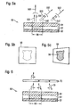
- Fig. 1 shows a schematic representation of a banknote 10, the two security elements 12 and 16, respectively, which are each formed according to an embodiment of the invention.
- the first security element represents a security thread 12 that emerges at certain window areas 14 on the surface of the banknote 10, while it is embedded in the intervening areas inside the banknote 10.
- the second security element is formed by a glued transfer element 16 of any shape
- Fig. 2 shows the basic layer structure of the security elements 12 and 16 in cross section.
- a smooth film 20 for example a PET film of good surface quality, is provided with an absorbent, dark background layer 22.
- Two or more, in the general case, n optically active layers 24-1, 24-2,... 24-n of liquid-crystalline material are applied to this background layer 22.
- the liquid crystal layers 24-1, 24-2,... 24-n may each have different but also partially the same light-polarizing or phase-shifting properties.
- Alignment layers and / or adhesive layers 26 may be provided between the liquid crystal layers, which serve to align the liquid crystals in the liquid crystal layers or the connection of the individual liquid crystal layers and to compensate for unevenness in the background.
- At least one of the liquid-crystalline layers 24-1, 24-2, ... 24-n consists of a cholesteric liquid-crystalline material and selectively reflects light in a first wavelength range with a first circular polarization direction.
- the dark background layer 22 is not part of the security element.
- the liquid crystal layers 24-1, 24-2,... 24-n and possible alignment and adhesive layers 26 are then applied directly to the film 20.
- FIG. 2 shows a security element 30 in which a first cholesteric liquid crystal layer 32 and on this a second cholesteric liquid crystal layer 34 are arranged on an absorbing, preferably black background layer 22. Due to the interplay of the two liquid crystal layers 32 and 34, the security element 30 has a novel color-shift effect, which conveys to the viewer a color impression that changes with the viewing direction. When viewed vertically, the security element 30 appears to the viewer in the exemplary embodiment blue / violet (reflected radiation 301), while viewed from an acute angle, it offers a red color impression (reflected radiation 302).
- This novel color interplay in which the color impression of the security element changes from short-wave to longer-wave light when tilted, is due to the fact that the first liquid crystal layer 32 blue light (arrow 321) in the vertical viewing direction and shorter-wave UV radiation (arrow 322) in the acute Viewing direction reflected.
- the second liquid crystal layer 34 is formed to reflect infrared radiation (arrow 341) in the perpendicular viewing direction and shorter wavelength red light (arrow 342) in the acute viewing direction.
- the two reflection components 321 and 342 lying outside the visible spectral range do not contribute to the color impression of the security element, so that a blue color impression 301 results for the viewer when viewed vertically and a long-wave red color impression 302 when viewed at an acute angle.
- the first and second liquid crystal layers 32 and 34 can each be printed on a smooth PET film of good surface quality.
- Suitable printing methods are all suitable printing processes for liquid-crystalline layers, such as intaglio, flexographic printing, knifecoating, curtain or blade techniques.
- the quality and the color spectrum of the individual layers can already be tested at this stage of production and, if appropriate, rejects rejects.
- the liquid crystal layers 32 and 34 are then laminated to the background layer 22 and the first liquid crystal layer 32, respectively, using commercially available laminating adhesives.
- the smoothness of the surface influences the degree of gloss of the security element.
- the laminating adhesive can compensate for unevenness in the surface, as can occur during the construction of a typical security thread 12, so that good gloss can also be achieved for such security elements.
- the carrier foils can be removed. This can be done for example via so-called separation or release layers. These are in particular UV coatings or waxes, which can be activated mechanically or thermally. When separating layers are used, they can be structured on the surface in order to locally promote or prevent orientation of the liquid crystals during application. By a partially different orientation of the liquid crystals so motifs such as characters or patterns can be introduced into the liquid crystal layers even when applied over the entire area.
- the adhesion of the liquid crystals to the support film must be less than the adhesion of the adhesive to the liquid crystals to permit separation.
- the adhesion of the adhesive to the layer to which the system is to be transferred must be better than the adhesion of the liquid crystals to the carrier film. It must also be better than the adhesion of the adhesive to the carrier film. The above requirements of the laminating adhesive are particularly important if the liquid crystal layer to be transferred is not formed over the entire surface.
- the second liquid-crystal layer 34 is laminated in an analogous manner to the first liquid-crystal layer 32, which is now located above the composite.
- the liquid crystal layers can each be laminated on top of each other, printed on top of each other or applied in a different way, wherein optionally not shown alignment layers or adhesive layers between the layers can be provided.
- a first cholesteric liquid crystal layer 42 and on this a second cholesteric liquid crystal layer 44 are applied to an absorbing, preferably black background layer 22.
- the first liquid crystal layer 42 is applied only in regions to the substrate 22 and forms a motif by the shape or the outline of the applied areas, in the exemplary embodiment a blazon 46.
- the second liquid crystal layer 44 is over the entire area on the first liquid crystal layer 42 or in the released areas on the substrate layer 22 applied.
- the two liquid crystal layers are matched to one another such that the coat of arms motif 46 when viewing the security element (FIG. Fig. 4 (b) ) is clearly visible to the viewer and disappears when tilting the security element 40, ie the transition from vertical to acute angle viewing, as in Fig. 4 (c) indicated by the dashed outline.
- the disappearance of the coat of arms motif 46 is achieved in that the partially applied liquid crystal layer 42 when tilting a color shift effect of blue (arrow 421) to ultraviolet (arrow 422) shows, while the second liquid crystal layer 44 has a changing between two colors of the visible spectral range color shift effect, and for example, varies between red (arrow 441) and green (arrow 442).
- a color impression 401 which results from the additive color mixing of the blue light 421 of the first liquid crystal layer 42 and the red light 441 of the second liquid crystal layer 44 thus results in the overlap region 48 of the two layers outside the overlap region, only the red color impression of the second liquid crystal layer 44 can be recognized. Due to the color contrast in the reflected light 401, the crest motif 46 clearly emerges for the viewer.
- the first liquid crystal layer 42 in the overlap region 48 only reflects ultraviolet light lying outside the visible spectral range to the observer.
- the liquid crystal layer 42 thus contributes neither to the color impression 402 of the security element 40 in the overlapping area 48 nor outside the overlapping area. Under acute viewing angle, the motif is therefore not visible, and the viewer has the impression that the crest motif 46 disappears when tilting the security element 40 from the vertical.
- a security element 50 with a motif appearing on tilting can be produced, as in FIG Fig. 5 illustrated.
- the areally applied liquid crystal layer 52 is formed so that it shows a color shift effect of infrared (arrow 521) to red (arrow 522) when tilting.
- the second liquid crystal layer 54 again shows a color shift effect between two colors of the visible spectral range, and varies, for example, between cyan (arrow 541) and violet (arrow 542).
- the subject 56 is not visible when viewed perpendicularly in the reflected light 501, since at most invisible infrared radiation from the first liquid crystal layer 52 is reflected in the vertical viewing direction. Only when the security element 50 is tilted does the subject become recognizable to the observer, since the first liquid crystal layer 52 then reflects red light to the viewer in the overlapping area 58, and the subject 56 in the reflected light 502 thus stands out from the violet color impression outside the overlapping area 58.
- FIGS. 6 to 11 show further embodiments to illustrate the invention, in which in addition to the color shift effect, especially the special lichtpolar environment of the liquid crystal layers are exploited.
- the polarization direction of the light is indicated in these figures by additional arrow symbols on the propagation vectors of the light.
- a circular polarization in which the circular motion of the electric field strength vector is clockwise from an observer's point of view is referred to as right circular polarization, counter polarization as left circular polarization.
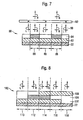
- the security element 60 of Fig. 6 includes two cholesteric liquid crystal layers 62 and 64 deposited on a dark background layer 22.
- the two liquid crystal layers 62 and 64 have the same color reflection spectrum, but differ in the orientation of the reflected circular polarization. While the first liquid crystal layer 62 in the embodiment reflects left circularly polarized light, the second liquid crystal layer 64 reflects right circularly polarized light. In contrast, left circularly polarized light is transmitted by the second liquid crystal layer 64 without substantial absorption. It is understood that the polarization directions given are for illustration only and, of course, can be chosen differently within the scope of the invention.
- Such opposing selective reflection can be achieved, for example, by forming the two cholesteric liquid crystal layers 62 and 64 from the same nematic liquid crystal system using mirror image twisting agents.
- a mirror-image helical arrangement of the rod-shaped liquid crystal molecules in the two liquid crystal layers can be achieved, so that one layer reflects right-handed, the other layer left circularly polarized light.
- the color of the light reflected from the liquid crystal layers depends on the viewing direction as in the above-described embodiments, and changes from red to green, for example, in the transition from vertical to acute viewing.
- the first liquid crystal layer 62 is in the embodiment of the Fig. 6 only partially in the form of a motif, such as a lettering, or a pattern ago. If the security element 60 is viewed without auxiliary means, then the color-shift effect of the second liquid-crystal layer 64 appears in the first place. In the overlapping region 68 of the two layers, the motif is recognizable with the same color impression, but with respect to its surroundings increased brightness, since in the overlap region 68 light of both circular polarization directions is reflected, while outside only neurosciencezirkular polarized light is reflected, as by the arrows 70 of the reflected light displayed.
- a circular polarizer 72 that transmits only left circularly polarized light
- the high brightness contrast pattern formed by the first liquid crystal layer 62 emerges because the circular polarizer 72 completely blankes out the right circularly polarized light reflected from the second liquid crystal layer 64.
- a circular polarizer 72 can be formed for example by a linear polarizer and a downstream ⁇ / 4 plate.
- the second liquid crystal layer 64 or both liquid crystal layers 62, 64 may be present in the form of motifs in an analogous manner.
- a motif in the second liquid crystal layer 64 can be made clearly visible by using a circular polarizer which transmits right circularly polarized light. With a viewing device containing both types of polarizers, the motifs can be easily displayed in one or both layers.
- Fig. 7 shows a security element 80 with a first cholesteric liquid crystal layer 82 and on the liquid crystal layer 82 partially applied ⁇ / 2 layer 84 containing nematic liquid crystals.
- nematic liquid crystals it is possible to produce optically active layers along the main crystal axes due to the different refractive indices of the rod-shaped liquid crystals.
- a ⁇ / 2 layer is obtained for the wavelength range in which the first liquid crystal layer 82 selectively reflects.
- the first liquid crystal layer 82 reflects light with a preselected circular polarization direction, for example, left circularly polarized light.
- the security element 80 reflects light with the opposite polarization direction, in the exemplary embodiment therefore right-circularly polarized light, since the incident unpolarized light is not affected by the ⁇ / 2 layer 84, the polarization direction of the reflected from the first liquid crystal layer 82, left circularly polarized light from the ⁇ / 2 layer 84, however, is just reversed by the path difference between the ordinary and extraordinary beams in its polarization orientation.
- the motif formed by the ⁇ / 2 layer 84 is barely discernible since the security element in the covered and uncovered areas reflects substantially the same amount of light and the unaided eye can not distinguish the circular polarization direction of the light.
- the security element 80 is viewed through a circular polarizer 92 which transmits only right-circularly polarized light, the motif formed in the ⁇ / 2 layer 84 emerges with a clear contrast.
- the image parts 88 covered by the ⁇ / 2 layer 84 appear bright, while the uncovered image parts 86 appear dark.
- a reverse (negative) image impression results when using a circular polarizer which transmits only left circularly polarized light.
- the circular polarizer 92 may be formed by, for example, a linear polarizer followed by a ⁇ / 4 plate.
- a nematic liquid crystal layer in the form of a motif may first be printed on a smooth PET film of good surface quality in a layer thickness selected such that a ⁇ / 2-layer receives. After physical drying to remove the solvent, the liquid crystal layer is crosslinked by means of ultraviolet radiation. Subsequently, a layer of cholesteric liquid-crystalline material is printed over the entire area of the PET film partially coated with nematic liquid-crystalline material. This layer is also crosslinked after physical drying by means of ultraviolet radiation. The two-layered liquid crystal structure thus produced is then laminated to the background layer 22 by means of commercially available laminating adhesives via the cholesteric liquid crystal layer now lying on top, which forms an absorbent substrate. Such an absorbent substrate can be provided, for example, by a security thread, which may have further security elements.
- the carrier film can be removed. This can be done for example via separating layers. These are in particular UV coatings or waxes, which can be activated mechanically or thermally. If no separating layer is provided, then the cholesteric liquid crystal layer printed over the entire surface can also serve as an auxiliary layer between the laminating adhesive and the PET film and thus prevent the film tear otherwise possible when the PET film is pulled off, which can occur, in particular, during the transfer of non-full-surface layers.
- the same auxiliary function can also take over a full-surface applied auxiliary layer of a UV coating or other suitable material that can be easily removed from the carrier film. Since uncontrolled sticking through the laminating adhesive is prevented by the full-surface application, the laminating adhesive can be printed over the entire surface.
- the security element has a three-layered liquid crystal structure in which a ⁇ / 2 layer is arranged between two cholesteric liquid crystal layers having the same light-polarizing properties.
- the security element 100 has a layer sequence applied to a dark, preferably black background layer 22, which comprises a first cholesteric liquid crystal layer 102, a ⁇ / 2 layer 104 and a second cholesteric liquid crystal layer 106.
- the light-polarizing properties of the first and second liquid crystal layers 102 and 106 are identical, such that the two layers in themselves reflect light in the same preselected wavelength range and in the same preselected circular polarization direction. All layers can be applied over the entire area or only in certain areas in order to form different or complementary motifs such as characters or patterns.
- the reflection properties of the different possible layer sequences are in the Fig. 8 illustrated. It is assumed that the two cholesteric liquid crystal layers 102 and 106 reflect left-circularly polarized light and the illumination of the security element takes place with unpolarized light.
- first area 110 in which only the the first liquid crystal layer 102 is present, left circularly polarized light is reflected.
- the security element In a second region 112, in which the first liquid crystal layer 102 is covered by the ⁇ / 2 layer 104, the security element reflects, as already described in connection with FIG Fig. 7 explains, right circularly polarized light.
- the upper liquid crystal layer 106 In a third region 114 in which all three layers are present, the upper liquid crystal layer 106 reflects left circularly polarized light and transmits right circularly polarized light. The transmitted light is converted by the ⁇ / 2 layer 104 into left circularly polarized light, which is then reflected by the first liquid crystal layer 102.
- the reflected light is converted by the ⁇ / 2 layer 104 again into right-circularly polarized light, which is transmitted from the second liquid crystal layer 106.
- the layer sequence 102, 104, 106 also reflects right-circularly polarized light in addition to left circularly polarized light, as in FIG Fig. 8 shown.
- the upper liquid crystal layer 106 reflects left circularly polarized light.
- the transmitted right circularly polarized light is also transmitted by the lower liquid crystal layer 102 and absorbed in the background layer 22.
- the security element thus reflects only left circularly polarized light in this area.
- the security element 120 of Fig. 9 includes, as the above-described security element 100 of Fig. 8 a layer sequence applied to a black background layer 22 comprising a first cholesteric liquid crystal layer 102, a ⁇ / 2 layer 104 and a second cholesteric liquid crystal layer 106.
- a layer sequence applied to a black background layer 22 comprising a first cholesteric liquid crystal layer 102, a ⁇ / 2 layer 104 and a second cholesteric liquid crystal layer 106.
- only the ⁇ / 2 layer 104 is in the form of a motif, while the first and second liquid crystal layers 102 and 106 are applied over the entire surface.
- the motif of the ⁇ / 2 layer 104 appears with the same color impression as its surroundings, but is already in the regions 126 due to the reflection of both the left circular and the right circularly polarized light by the substantially double amount of reflected light recognizable without aids.
- the security element 120 is illuminated by a circular polarizer 122 with right circularly polarized light, the subject appears to the viewer 124 without further aids having strong contrast since the right circularly polarized light reflects in the areas 126 in which all three layers overlap while being transmitted in regions 128 without ⁇ / 2 layer 104 from the upper and lower liquid crystal layers 106 and 102, respectively, and absorbed in the black background layer 22.
- Fig. 10 shows a security element 130 according to a further embodiment of the invention, with respect to its layer sequence substantially as the security element 120 of Fig. 9 is constructed.
- the intermediate layer 132 of the security element 130 is constructed from two ⁇ / 4 partial layers 134 and 136, which can be locally rotated relative to one another in their orientation in the layer plane.
- right-circularly polarized light is therefore - analogous to the partial area 128 of FIG Fig. 9 - Transmitted from the layer sequence and finally absorbed by the background layer 22.
- the intermediate layer 132 causes a certain proportion of right-circularly polarized light to be reflected by the layer sequence ,
- the size of the reflected portion decreases continuously with increasing rotation angle.
- angle of rotation ⁇ in different surface areas of the intermediate layer 132, for example, halftone motifs can be encoded in the security element, which barely appear when illuminated with unpolarized light, but appear in the case of illumination with circularly polarized light as greyscale images for the viewer without further aids ,
- the ⁇ / 2 layer can of course also be replaced by two ⁇ / 4-part layers. These ⁇ / 4-part layers may also be locally rotated in their orientation in the layer plane against each other.
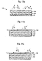
- Fig. 11 shows an embodiment in which both the color effects and the polarization effects of the liquid crystal layers are utilized.
- Fig. 11 (a)
- Fig. 12 shows the construction of a security element 150 having an absorbent underlying layer 22, a first cholesteric liquid crystal layer 152 and a second cholesteric liquid crystal layer deposited thereon 154th
- the first liquid crystal layer 152 has a first color-shift effect, for example from green to blue, and in addition only reflects light of a preselected circular polarization direction, for example right-circularly polarized light.
- the second liquid crystal layer 154 has a second color shift effect, for example from magenta to green, and also reflects only light of the circular polarization direction opposite the first liquid crystal layer, in the exemplary embodiment left circularly polarized light. If the security element 150 is viewed when illuminated with unpolarized light and without auxiliary means, then the two color shift effects are superimposed by additive color mixing of the reflected light.
- each of the liquid crystal layers 152, 154 may also be replaced by a combination of a ⁇ / 2 layer with a cholesteric layer mirroring the original layer.
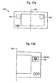
- a banknote 160 equipped with a two-part security arrangement comprising a security element 162 and a presentation element 164 is shown.
- the security element 162 and the presentation element 164 are arranged on the banknote 160 such that, when the banknote is folded along the center line 166, they come to lie on one another, as in FIG Fig. 12 (b) shown. It is understood that such an arrangement of the security element 162 and the display element 164 is not mandatory and that the elements 162,164 can of course also be arranged at other locations on the banknote 160, as long as it is ensured that they come to rest when folding the banknote ,
- the security element 162 consists of a layer sequence of cholesteric and / or nematic liquid crystal layers applied to a transparent film, as in FIG Fig. 2 shown, but without the dark background layer 22.
- the layers may be applied over the entire surface or even in regions, to form different or complementary motifs.
- the layer sequence as such can also be present on the transparent film in the form of a motif.
- the security element 162 is present in a papermaking-made or punched-out window of the banknote 160 and appears in the unfolded position of the banknote in reflected light or transmitted light substantially transparent and inconspicuous.
- the dark background layer which is essential to the visibility of the described color or polarization effects, is provided by the separate display element 164 in this embodiment and may be formed, for example, by a commercial ink printed on one side of the bill. Only when the banknote, as in Fig. 12 (b) , is folded so that the security element 162 comes to lie on the display element 164, the intended color and / or polarization effects can be detected. In the embodiment occurs after folding the banknote 160, a previously unrecognizable crest motif 168 in appearance. It is understood that a motif may also be present in the presentation element 164, in particular in addition to the motif in the security element 162, wherein the two motifs may complement one another and thereby form an encoding.
- the security element 162 is present as one of the security elements described above, including the dark background layer 22, and the presentation element 164 includes a circular polarizer formed by, for example, a linear polarizer and a downstream ⁇ / 4 plate.
- the detection mechanisms described above for the motifs introduced into the security element 162 when viewed through a circular polarizer can then be realized by folding the banknote 160, so that the user can carry out self-authentication of the security element and thus of the banknote 160 without additional aids.
- the security element 162 consists of a layer sequence applied to a dark background layer, as in FIG Fig. 7 which comprises a first cholesteric liquid crystal layer and a ⁇ / 2 layer applied to these in regions, which contains nematic liquid crystals.
- the security element 162 may be formed here for example by a glued transfer element or a security thread. In the unfolded position of the banknote, the security element 162 essentially only shows a color shift effect in incident light. The motif formed by the ⁇ / 2 layer, however, is hardly recognizable.
- the display element 164 is present in a papermaking or punched-out window of the banknote 160 and consists of a cholesteric liquid crystal layer applied to a transparent film whose light-polarizing properties are identical to those of the first cholesteric liquid crystal layer of the security element 162.
- the two layers individually reflect light in the same preselected wavelength range and with the same preselected circular polarization direction.
- the presentation element 164 appears in the unfolded position of the banknote in incident or transmitted light substantially transparent and inconspicuous.
- the security element consists of a liquid crystal layer applied to a transparent film.
- the security element as well as the security element lies in the Fig. 12 illustrated self-authenticating security arrangement in a papermaking or punched window, for example, a banknote ago.
- the partially applied in the form of a motif liquid crystal layer appears transparent and unobtrusive both in reflected light and transmitted light and is essentially indistinguishable from the surrounding transparent film.
- a separate display element which is arranged at another point of the banknote so that the security element comes to rest when folding the banknote on this, the typical liquid crystal color shift effects can be made visible by providing a dark, preferably black background layer.
- a background layer can be provided, for example, by printing one side of the banknote with a commercially available printing ink.
- the embodiments for self-authenticating security arrangement can also be provided on a plastic document, such as a Kunststoffbanknote.
- the transparent window is preferably formed by a non-printed area of the document.
Landscapes
- Health & Medical Sciences (AREA)
- Toxicology (AREA)
- General Health & Medical Sciences (AREA)
- Physics & Mathematics (AREA)
- General Physics & Mathematics (AREA)
- Spectroscopy & Molecular Physics (AREA)
- Finance (AREA)
- Accounting & Taxation (AREA)
- Business, Economics & Management (AREA)
- Chemical & Material Sciences (AREA)
- Crystallography & Structural Chemistry (AREA)
- Polarising Elements (AREA)
- Credit Cards Or The Like (AREA)
- Decoration By Transfer Pictures (AREA)
- Liquid Crystal (AREA)
- Laminated Bodies (AREA)
- Acyclic And Carbocyclic Compounds In Medicinal Compositions (AREA)
Abstract
Description
Die Erfindung betrifft ein Sicherheitselement zur Absicherung von Wertgegenständen mit einer zumindest bereichsweise vorliegenden ersten optisch aktiven Schicht aus cholesterischem flüssigkristallinem Material. Die Erfindung betrifft ferner ein Verfahren zum Herstellen eines derartigen Sicherheitselements, eine Sicherheitsanordnung, die neben einem solchen Sicherheitselement ein separates Darstellungselement umfasst, sowie ein Sicherheitspapier und einen Wertgegenstand, die mit einem solchen Sicherheitselement oder einer solchen Sicherheitsanordnung ausgestattet sind.The invention relates to a security element for securing valuables with a first optically active layer of cholesteric liquid-crystalline material present at least in regions. The invention further relates to a method for producing such a security element, a security arrangement which, in addition to such a security element, comprises a separate display element, as well as a security paper and a valuable article, which are equipped with such a security element or security arrangement.
Wertgegenstände, wie etwa Markenartikel oder Wertdokumente, werden zur Absicherung oft mit Sicherheitselementen ausgestattet, die eine Überprüfung der Echtheit des Wertgegenstands gestatten und die zugleich als Schutz vor unerlaubter Reproduktion dienen. ,Valuables, such as branded goods or documents of value, are often provided with security elements for the purpose of protection, which allow verification of the authenticity of the object of value and at the same time serve as protection against unauthorized reproduction. .
Vielfach werden als Sicherheitselemente optisch variable Elemente eingesetzt, die dem Betrachter unter unterschiedlichen Betrachtungswinkeln einen unterschiedlichen Bildeindruck, beispielsweise einen unterschiedlichen Farbeindruck vermitteln. Aus der Druckschrift
Bei den beschriebenen Sicherheitselementen führt der Farbkippeffekt der Flüssigkristallschichten aufgrund der physikalischen Gegebenheiten stets zu einer Verschiebung der reflektierten Lichtwellenlänge vom längerwelligen Bereich bei senkrechter Betrachtung zum kürzerwelligen Bereich bei Betrachtung der Schichten unter einem spitzen Winkel. Die Möglichkeiten zur Erzeugung unterschiedlicher Farbkippeffekte sind daher begrenzt.In the described security elements, the color shift effect of the liquid crystal layers due to the physical conditions always leads to a shift of the reflected light wavelength from the longer wavelength range when viewed perpendicularly to the shorter wavelength range when viewing the layers at an acute angle. The possibilities for generating different color shift effects are therefore limited.
Aus der Druckschrift
Die Druckschrift
In der Druckschrift
Die Druckschrift
Die Druckschrift
Die Druckschrift
Die Druckschrift
Ausgehend davon liegt der Erfindung die Aufgabe zugrunde, ein Sicherheitselement der eingangs genannten Art mit hoher Fälschungssicherheit anzugeben, das die Nachteile des Standes der Technik vermeidet.The publication
Based on this, the present invention seeks to provide a security element of the type mentioned above with high security against counterfeiting, which avoids the disadvantages of the prior art.
Diese Aufgabe wird durch das Sicherheitselement mit den Merkmalen des Hauptanspruchs gelöst. Ein Verfahren zu seiner Herstellung, eine Sicherheitsanordnung und ein Wertgegenstand mit einem solchen Sicherheitselement sind in den nebengeordneten Ansprüchen angegeben. Weiterbildungen der Erfindung sind Gegenstand der Unteransprüche.This object is achieved by the security element having the features of the main claim. A method for its production, a security arrangement and a valuable article with such a security element are given in the independent claims. Further developments of the invention are the subject of the dependent claims.
Die Erfindung enthält ein Sicherheitselement nach Anspruch 1.The invention contains a security element according to claim 1.
Dadurch lassen sich neuartige, die lichtpolarisierenden oder phasenschiebenden Eigenschaften der Flüssigkristallschichten ausnutzende Effekte erzielen, die die vorteilhafte Fälschungssicherheit bekannter Sicherheitselemente beibehalten oder sogar erhöhen. Wie nachfolgend im Detail erläutert, erlaubt die additive Farbmischung der Reflexionsspektren der beiden optisch aktiven Schichten die Erzeugung breiterer und ungewöhnlicher Farbkippeffekte. Auch lässt sich die Intensität des insgesamt reflektierten Lichts durch die Nutzung der beiden gegenläufigen zirkularen Polarisationsrichtungen erhöhen. In eine oder mehrere der Flüssigkristallschichten können darüber hinaus Informationen codiert werden, die sich nur unter Verwendung von Zirkularpolarisatoren auslesen lassen. In einer vorteilhaften Erfindungsvariante ist die zweite zirkulare Polarisationsrichtung des Lichts, das die zweite optisch aktive Schicht selbst oder in Zusammenwirkung mit der ersten optisch aktiven Schicht reflektiert, gegenläufig zur ersten zirkularen Polarisationsrichtung. In einer ebenfalls vorteilhaften Variante der Erfindung entspricht der von der zweiten optisch aktiven Schicht reflektierte Wellenlängenbereich dem ersten Wellenlängenbereich.As a result, it is possible to achieve novel effects which exploit the light-polarizing or phase-shifting properties of the liquid crystal layers, which retain or even increase the advantageous security against forgery of known security elements. As explained in detail below, the additive color mixing of the reflection spectra of the two optically active layers allows the generation of wider and unusual color-shift effects. Also, the intensity of the total reflected light can be increased by the use of the two counter-rotating circular polarization directions. In addition, information which can only be read out using circular polarizers can be coded in one or more of the liquid crystal layers. In an advantageous variant of the invention, the second circular polarization direction of the light, which reflects the second optically active layer itself or in cooperation with the first optically active layer, is opposite to the first circular polarization direction. In a likewise advantageous variant of the invention, the wavelength range reflected by the second optically active layer corresponds to the first wavelength range.
Die zweite optisch aktive Schicht bildet gemäß einer bevorzugten Ausgestaltung eine phasenschiebende Schicht. Mit Vorteil bildet die zweite Schicht eine λ/2-Schicht für Licht aus dem ersten Wellenlängenbereich. Dabei ist die λ/2-Schicht vorzugsweise aus nematischem flüssigkristallinem Material gebildet, das aufgrund der optischen Anisotropie der ausgerichteten stäbchenförmigen Flüssigkristalle die Herstellung optisch aktiver Schichten ermöglicht.The second optically active layer forms a phase-shifting layer according to a preferred embodiment. Advantageously, the second layer forms a λ / 2 layer for light from the first wavelength range. In this case, the λ / 2 layer is preferably formed from nematic liquid-crystalline material which, because of the optical anisotropy of the aligned rod-shaped liquid crystals, makes it possible to produce optically active layers.
Um den Effekt der λ/2-Schicht gebietsweise abzuschwächen und/oder neue Effekte zu erzeugen, kann die λ/2-Schicht auch aus mehreren übereinander angeordneten und bereichsweise gegeneinander in der Schichtebene verdrehten Teilschichten gebildet sein. Besonders vorteilhaft sind die Teilschichten dabei durch zwei λ/4-Schichten gebildet. Durch eine bereichsweise unterschiedliche Verdrehung der beiden λ/4-Teilschichten lässt sich ihr Einfluss auf zirkular polarisiertes Licht gezielt einsetzen, um beispielsweise codierte Halbtonbilder zu erzeugen.In order to attenuate the effect of the λ / 2 layer in regions and / or to produce new effects, the λ / 2 layer may also be formed from a plurality of partial layers arranged one above the other and partially rotated relative to one another in the layer plane. The partial layers are particularly advantageously formed by two λ / 4 layers. By partially different rotation of the two λ / 4-part layers, their influence on circularly polarized light can be selectively used to produce, for example, coded halftone images.
In den Ausgestaltungen mit λ/2-Schicht kann mit Vorteil eine dritte optisch aktive Schicht aus cholesterischem flüssigkristallinem Material vorgesehen sein, die wie die erste optisch aktive Schicht Licht in dem ersten Wellenlängenbereich mit der ersten zirkularen Polarisationsrichtung selektiv reflektiert. Die λ/2-Schicht ist dabei zumindest bereichsweise zwischen der ersten und der dritten optisch aktiven Schicht angeordnet.In the embodiments with λ / 2-layer can advantageously be provided a third optically active layer of cholesteric liquid-crystalline material, which selectively reflects light in the first wavelength range with the first circular polarization direction as the first optically active layer. The λ / 2-layer is arranged at least partially between the first and the third optically active layer.
Nach einer weiteren bevorzugten Erfindungsvariante entspricht die zweite zirkulare Polarisationsrichtung des Lichts, das die zweite optisch aktive Schicht selbst oder in Zusammenwirkung mit der ersten optisch aktiven Schicht reflektiert, der ersten zirkularen Polarisationsrichtung. Der von der zweiten optisch aktiven Schicht reflektierte Wellenlängenbereich unterscheidet sich in einer ebenfalls vorteilhaften Variante der Erfindung von dem ersten Wellenlängenbereich.According to a further preferred variant of the invention, the second circular polarization direction of the light which reflects the second optically active layer itself or in cooperation with the first optically active layer corresponds to the first circular polarization direction. The wavelength range reflected by the second optically active layer differs in a likewise advantageous variant of the invention from the first wavelength range.
Insbesondere in Verbindung mit den beiden letztgenannten Erfindungsvarianten ist die zweite optisch aktive Schicht zweckmäßig, wie die erste optisch aktive Schicht, aus einem cholesterischen flüssigkristallinen Material gebildet. Dabei können für die erste und zweite cholesterische Flüssigkristallschicht verschiedene Flüssigkristalle zum Einsatz kommen. Die beiden Schichten können sich aber auch nur durch die Helizität der Flüssigkristallstruktur unterscheiden, wie sie beispielsweise durch Verwendung spiegelbildlicher Verdriller erzeugt werden kann.In particular, in conjunction with the two last-mentioned variants of the invention, the second optically active layer is expedient, like the first optically active layer, formed from a cholesteric liquid-crystalline material. In this case, different liquid crystals can be used for the first and second cholesteric liquid crystal layer. However, the two layers can differ only by the helicity of the liquid crystal structure, as can be generated for example by using mirror-image Verdriller.
In allen beschriebenen Ausgestaltungen kann vorgesehen sein, dass die erste optisch aktive Schicht in eine erste Betrachtungsrichtung nur Licht aus dem nicht sichtbaren Teil des Spektrums reflektiert. Dagegen reflektiert die erste optisch aktive Schicht in eine zweite Betrachtungsrichtung vorzugsweise sichtbares Licht einer ersten Farbe. Auch die zweite optisch aktive Schicht reflektiert in einer vorteilhaften Ausgestaltung in eine oder die zweite Betrachtungsrichtung nur Licht aus dem nicht sichtbaren Teil des Spektrums. Auch sie reflektiert mit Vorteil in eine oder die erste Betrachtungsrichtung sichtbares Licht einer dritten Farbe.In all described embodiments it can be provided that the first optically active layer only reflects light from the non-visible part of the spectrum in a first viewing direction. In contrast, the first optically active layer preferably reflects visible light of a first color in a second viewing direction. Also, the second optically active layer reflects in an advantageous embodiment in one or the second viewing direction only light from the invisible part of the spectrum. It also advantageously reflects visible light of a third color in one or the first viewing direction.
Insgesamt kann dann in einer besonders bevorzugten Ausgestaltung vorgesehen sein, dass eine der beiden optisch aktiven Schichten als Licht aus dem nicht sichtbaren Teil des Spektrums Infrarotstrahlung, und die andere der beiden optisch aktiven Schichten als Licht aus dem nicht sichtbaren Teil des Spektrums Ultraviolettstrahlung in die entsprechende Betrachtungsrichtung reflektiert.Overall, it can then be provided in a particularly preferred embodiment that one of the two optically active layers as light from the invisible part of the spectrum infrared radiation, and the other of the two optically active layers as light from the non-visible part of the spectrum ultraviolet radiation in the corresponding Viewing direction reflected.
Wenn die erste optisch aktive Schicht in eine erste Betrachtungsrichtung nur Licht aus dem nicht sichtbaren Teil des Spektrums und gegebenenfalls in eine zweite Betrachtungsrichtung sichtbares Licht einer ersten Farbe reflektiert, so kann die zweite optisch aktive Schicht auch so ausgebildet sein, dass sie in die erste Betrachtungsrichtung sichtbares Licht einer dritten Farbe und in die zweite Betrachtungsrichtung sichtbares Licht einer von der dritten Farbe verschiedenen vierten Farbe reflektiert.If the first optically active layer only reflects light from the non-visible part of the spectrum and possibly visible light in a second viewing direction of a first color in a first viewing direction, then the second optically active layer may also be configured to be in the first viewing direction visible light of a third color and in the second viewing direction visible light of a fourth color other than the third color reflected.
In anderen Ausgestaltungen reflektiert die erste optisch aktive Schicht in eine erste Betrachtungsrichtung sichtbares Licht einer ersten Farbe und in eine zweite Betrachtungsrichtung sichtbares Licht einer von der ersten Farbe unterschiedlichen zweiten Farbe. Die zweite optisch aktive Schicht kann dann in die zweite Betrachtungsrichtung nur Licht aus dem nicht sichtbaren Teil des Spektrums und gegebenenfalls in die erste Betrachtungsrichtung sichtbares Licht einer dritten Farbe reflektieren. Alternativ reflektiert die zweite optisch aktive Schicht in die erste Betrachtungsrichtung sichtbares Licht einer von der ersten Farbe verschiedenen dritten Farbe und in die zweite Betrachtungsrichtung Licht einer von der dritten Farbe verschiedenen vierten Farbe.In other embodiments, the first optically active layer reflects visible light of a first color in a first viewing direction and visible light of a second color different from the first color in a second viewing direction. The second optically active layer can then reflect in the second viewing direction only light from the non-visible part of the spectrum and optionally visible in the first viewing direction light of a third color. Alternatively, the second optically active layer reflects visible light of a third color other than the first color in the first viewing direction and light of a fourth color other than the third color in the second viewing direction.
In allen Ausgestaltungen kann die dritte optisch aktive Schicht in Form von Zeichen und/oder Mustern vorliegen. Auch können weitere optisch aktive Schichten aus nematischem und/oder cholesterischem flüssigkristallinem Material vorgesehen sein. Zumindest eine der optisch aktiven Schichten aus cholesterischem flüssigkristallinem Material und/oder gegebenenfalls zumindest eine Schicht aus nematischem flüssigkristallinem Material liegt zweckmäßig in Form von Pigmenten vor, welche in eine Bindemittelmatrix eingebettet sind. Solche Pigmente sind einfacher zu drucken als Flüssigkristalle aus Lösung und stellen keine so hohen Anforderungen an die Glätte des Untergrunds. Darüber hinaus benötigen die pigmentbasierten Druckfarben keine die Ausrichtung fördernden Maßnahmen.In all embodiments, the third optically active layer may be in the form of characters and / or patterns. It is also possible to provide further optically active layers of nematic and / or cholesteric liquid-crystalline material. At least one of the optically active layers of cholesteric liquid-crystalline material and / or optionally at least one layer of nematic liquid-crystalline material is expediently present in the form of pigments which are embedded in a binder matrix. Such pigments are easier to print than liquid crystals from solution and do not place such high demands on the smoothness of the substrate. In addition, pigment-based inks do not require alignment-promoting measures.
In einer bevorzugten Ausgestaltung sind die optisch aktiven Schichten zumindest teilweise, vorzugsweise vollflächig, auf einem dunklen, vorzugsweise schwarzen Untergrund angeordnet. Der dunkle Untergrund kann dabei selbst in Form von Zeichen und/oder Mustern vorliegen. Er kann insbesondere gedruckt, durch Einfärben eines Substrats oder durch Einwirkung eines Laserstrahls auf ein Substrat erzeugt sein.In a preferred embodiment, the optically active layers are at least partially, preferably over the entire surface, arranged on a dark, preferably black background. The dark background can be present even in the form of signs and / or patterns. In particular, it can be printed, produced by coloring a substrate or by the action of a laser beam on a substrate.
Die optisch aktiven Schichten und gegebenenfalls der dunkle Untergrund liegen in zweckmäßigen Ausgestaltungen auf einem Substrat vor. Das Substrat ist dabei mit Vorteil aus Papier oder Kunststoff gebildet.The optically active layers and, where appropriate, the dark background are in expedient embodiments on a substrate. The substrate is advantageously formed from paper or plastic.
In vorteilhaften Ausgestaltungen bildet das Sicherheitselement einen Sicherheitsfaden, ein Etikett oder ein Transferelement.In advantageous embodiments, the security element forms a security thread, a label or a transfer element.
Die Erfindung umfasst nach ein Verfahren nach Anprusch 2.The invention comprises according to a method according to claim 2.
Das flüssigkristalline Material kann aus einem Lösungsmittel oder aus der Schmelze aufgebracht werden. Ferner kann insbesondere cholesterisches flüssigkristallines Material in pastöser Form als UV-härtbare cholesterische Mischung aufgebracht werden, wobei ein solches System weder typische Lösungsmittel einschließt noch auf einer Schmelze oder Pigmenten basiert, sondern stattdessen weitere UV-härtbare Lacke enthält. Je nach angewandtem Verfahren wird das flüssigkristalline Material anschließend zur Entfernung des Lösungsmittels physikalisch getrocknet, ausgerichtet und gehärtet. Die Ausrichtung kann direkt über die Trägerfolie oder über so genannte Ausrichtungs- bzw. Alignmentschichten, durch Ausübung von Scherkräften, mithilfe elektrostatischer Methoden usw. erfolgen. Zur Härtung des flüssigkristallinen Materials kann dieses vernetzt werden, beispielsweise mittels ultravioletter Strahlung oder mittels Elektronenstrahl (ESH). Das flüssigkristalline Material kann aber auch durch Zugabe bestimmter Additive fixiert werden.The liquid crystalline material may be applied from a solvent or from the melt. Furthermore, in particular, cholesteric liquid crystalline material can be applied in pasty form as a UV-curable cholesteric mixture, wherein such a system neither includes typical solvents nor is based on a melt or pigments, but instead contains further UV-curable lacquers. Depending on the method used, the liquid crystalline material is then physically dried, aligned and cured to remove the solvent. The alignment can be done directly over the carrier film or via so-called alignment layers, by applying shear forces, by electrostatic methods, etc. For hardening the liquid-crystalline material, it can be crosslinked, for example by means of ultraviolet radiation or by means of electron beam (ESH). However, the liquid-crystalline material can also be fixed by adding certain additives.
Mit Vorteil werden nach dem Aufbringen aller optisch aktiven Schichten die eine oder gegebenenfalls beide Trägerfolien entfernt. Dies geschieht insbesondere über Trennschichten oder durch Verwendung eines Laminierklebstoffes, dessen Haftung zur Trägerfolie geringer ist, als seine Haftung in Bezug auf die zugehörige optisch aktive Schicht.Advantageously, after the application of all the optically active layers, the one or, if appropriate, both carrier films are removed. This is done in particular via separating layers or by using a laminating adhesive whose adhesion to the carrier film is lower than its adhesion with respect to the associated optically active layer.
Alternativ kann auf die auf der Trägerfolie vorliegende optisch aktive Schicht eine vollflächige Hilfsschicht aufgebracht werden, deren Haftung zur Trägerfolie geringer ist als ihre Haftung in Bezug auf die optisch aktive Schicht, um die Trennung zu ermöglichen. Dadurch lässt sich der Laminierklebstoff vollflächig aufbringen, wobei gleichzeitig unkontrolliertes Verkleben verhindert wird. Die Hilfsschicht ist dabei mit Vorteil eine UV-Lackschicht.Alternatively, an all-over auxiliary layer can be applied to the optically active layer present on the carrier film whose adhesion to the carrier film is less than its adhesion with respect to the optically active layer in order to allow the separation. As a result, the laminating adhesive can be applied over the entire surface, while preventing uncontrolled sticking. The auxiliary layer is advantageously a UV lacquer layer.
Die Ausbildung der cholesterischen Flüssigkristallschichten kann mit Vorteil durch Kombination eines nematischen Flüssigkristallsystems mit einem Verdriller geschehen. Dabei können die beiden cholesterischen Flüssigkristallschichten durch Kombination eines nematischen Flüssigkristallsystems mit aufeinander abgestimmten ersten und zweiten Verdrillern gebildet werden, so dass sich die Flüssigkristalle der ersten und zweiten Schicht in zueinander spiegelbildlichen Helixstrukturen anordnen.The formation of the cholesteric liquid crystal layers can be done with advantage by combination of a nematic liquid crystal system with a Verdriller. In this case, the two cholesteric liquid crystal layers can be formed by combination of a nematic liquid crystal system with matched first and second twisters, so that the liquid crystals of the first and second layers are arranged in mirror-image helical structures.
Die Erfindung enthält ferner eine Sicherheitsanordnung für Sicherheitspapiere, Wertgegenstände und dergleichen mit einem Sicherheitselement der beschriebenen Art oder einem nach dem beschriebenen Verfahren herstellbaren Sicherheitselement sowie einem separaten Darstellungselement, das in Zusammenwirkung mit dem Sicherheitselement einen Farbkippeffekt und/oder einen Polarisationseffekt und/oder einen Helligkeitseffekt bzw. eine Intensitätsverstärkung für den Betrachter erkennbar macht.The invention further includes a security arrangement for security papers, valuables and the like having a security element of the type described or a security element producible according to the method described and a separate display element which, in cooperation with the security element, has a color shift effect and / or a polarization effect and / or a brightness effect ., an intensity gain for the viewer makes recognizable.
In einer bevorzugten Ausgestaltung ist das Sicherheitselement dabei ohne dunkle Untergrundschicht ausgebildet, während das separate Darstellungselement einen dunklen, vorzugsweise schwarzen Untergrund umfasst.In a preferred embodiment, the security element is formed without a dark background layer, while the separate display element comprises a dark, preferably black background.
In einer anderen, ebenfalls bevorzugten Ausgestaltung kann das Sicherheitselement auch eine dunkle Untergrundschicht umfassen. Das separate Darstellungselement umfasst in dieser Ausgestaltung einen Linear- oder Zirkularpolarisator, mit dem die Farb- und/oder Polarisationseffekte des Sicherheitselements sichtbar gemacht werden können.In another, likewise preferred embodiment, the security element can also comprise a dark background layer. The separate display element in this embodiment comprises a linear or circular polarizer with which the color and / or polarization effects of the security element can be made visible.
In einer weiteren bevorzugten Ausgestaltung weist das Sicherheitselement eine Schicht aus cholesterischem flüssigkristallinem Material sowie eine Schicht aus nematischem flüssigkristallinem Material auf, die in einem Überlappungsbereich übereinander angeordnet sind. Das separate Darstellungselement umfasst in dieser Ausgestaltung eine Schicht aus cholesterischem flüssigkristallinem Material, das in Zusammenwirkung mit dem Sicherheitselement eine bereichsweise Intensitätsverstärkung für den Betrachter erkennbar macht.In a further preferred embodiment, the security element has a layer of cholesteric liquid-crystalline material and a layer of nematic liquid-crystalline material, which are arranged one above the other in an overlapping region. In this embodiment, the separate display element comprises a layer of cholesteric liquid-crystalline material which, in cooperation with the security element, makes a region-wise increase in intensity visible to the viewer.
Ferner umfasst die Erfindung eine Sicherheitsanordnung für Sicherheitspapiere, Wertgegenstände und dergleichen mit einem Sicherheitselement, das zumindest eine Schicht aus flüssigkristallinem Material aufweist, die zumindest bereichsweise auf einer transparenten Trägerfolie angeordnet ist, und einem separaten Darstellungselement, das in Zusammenwirkung mit dem Sicherheitselement einen Farbkippeffekt für den Betrachter erkennbar macht und einen dunklen, vorzugsweise schwarzen Untergrund umfasst.Furthermore, the invention comprises a security arrangement for security papers, valuables and the like having a security element comprising at least one layer of liquid-crystalline material, which is arranged at least partially on a transparent carrier film, and a separate display element, which in cooperation with the security element a color shift effect for the Viewer makes recognizable and includes a dark, preferably black background.
Die Erfindung umfasst weiter einen Wertgegenstand, wie einen Markenartikel, ein Wertdokument oder dergleichen, mit einem Sicherheitselement oder einer Sicherheitsanordnung der beschriebenen Art. Der Wertgegenstand kann insbesondere ein Sicherheitspapier, ein Wertdokument oder eine Produktverpackung sein. Das Sicherheitselement ist dabei mit Vorteil in einem Fensterbereich des Wertgegenstands angeordnet.The invention further comprises a valuable article, such as a branded article, a value document or the like, having a security element or a security arrangement of the type described. The valuable article may, in particular, be a security paper, a value document or a product packaging. The security element is advantageously arranged in a window region of the valuable article.
Besonders bevorzugt ist ein flexibler Wertgegenstand, bei dem das Sicherheitselement und das Darstellungselement durch Biegen oder Falten des Wertgegenstands zur Selbstauthentifizierung übereinander legbar sind.Particularly preferred is a flexible object of value, in which the security element and the presentation element can be laid one on top of the other by bending or folding the valuables for self-authentication.
Wertgegenstände im Sinne der vorliegenden Erfindung sind insbesondere Banknoten, Aktien, Ausweise, Kreditkarten, Anleihen, Urkunden, Gutscheine, Schecks, hochwertige Eintrittskarten, aber auch andere fälschungsgefährdete Papiere, wie Pässe und sonstige Ausweisdokumente, sowie Produktsicherungselemente, wie Etiketten, Siegel, Verpackungen und dergleichen. Der Begriff "Wertgegenstand" schließt im Folgenden alle derartigen Gegenstände, Dokumente und Produktsicherungsmittel ein. Unter dem Begriff "Sicherheitspapier" wird die noch nicht umlauffähige Vorstufe zu einem Wertdokument verstanden, die neben dem Sicherheitselement weitere Echtheitsmerkmale, wie z.B. im Volumen vorgesehene Lumineszenzstoffe, aufweisen kann. Sicherheitspapier liegt üblicherweise in quasi endloser Form vor und wird zu einem späteren Zeitpunkt weiterverarbeitet.Valuables within the meaning of the present invention are in particular banknotes, shares, identity cards, credit cards, bonds, certificates, vouchers, checks, high-quality admission tickets, but also other papers that are subject to counterfeiting, such as passports and other identity documents, as well as product security elements such as labels, seals, packaging and the like , The term "object of value" in the following includes all such objects, documents and product protection means. The term "security paper" is understood to mean the precursor that can not yet be processed to a value document which, in addition to the security element, has further authenticity features, such as e.g. in volume provided luminescent substances may have. Security paper is usually in quasi-endless form and will be further processed at a later date.
Weitere Ausführungsbeispiele sowie Vorteile der Erfindung werden nachfolgend anhand der Figuren erläutert, bei deren Darstellung auf eine maßstabs- und proportionsgetreue Wiedergabe verzichtet wurde, um die Anschaulichkeit zu erhöhen.Further exemplary embodiments and advantages of the invention are explained below with reference to the figures, in the representation of which a representation true to scale and proportion has been dispensed with in order to increase the clarity.
Es zeigen:
- Fig.1
- eine schematische Darstellung einer Banknote mit einem eingebetteten Sicherheitsfaden und einem aufgeklebten Transferelement, jeweils nach einem Ausführungsbeispiel der Erfindung,
- Fig. 2
- den allgemeinen Schichtaufbau eines erfindungsgemäßen Sicherheitselements im Querschnitt,
- Fig. 3
- ein Sicherheitselement im Querschnitt,
- Fig. 4
- in (a) den Querschnitt eines Sicherheitselements nach einem anderen Ausführungsbeispiel der Erfindung, in (b) eine Ansicht dieses Sicherheitselements bei senkrechter Betrachtung und in (c) eine Ansicht bei spitzwinkliger Betrachtung,
- Fig. 5
- eine Darstellung wie in
Fig. 4 eines Sicherheitselements nach einem weiteren Ausführungsbeispiel der Erfindung, - Fig. 6
- ein Sicherheitselement nach einer Gestaltung zur Illustration der Erfindung mit einem Zirkularpolarisator zum Lesen der codierten Information,
- Fig. 7
- eine Darstellung wie in
Fig. 6 eines Sicherheitselements nach einer weiteren Gestaltung zur Illustration der Erfindung, - Fig. 8
- das Prinzip von Sicherheitselementen mit einem dreischichtigen Flüssigkristallaufbau, bei dem eine λ/2-Schicht zwischen zwei cholesterischen Flüssigkristallschichten angeordnet ist,
- Fig. 9
- ein Sicherheitselement nach dem Prinzip der
Fig. 8 bei Beleuchtung mit rechtszirkular polarisiertem Licht, - Fig.10
- ein weiteres Sicherheitselement nach dem Prinzip der
Fig. 8 mit einer in zwei λ/4-Schichten unterteilten λ/2-Schicht, - Fig. 11
- ein Sicherheitselement nach einer weiteren Gestaltung zur Illustration der Erfindung, bei dem sowohl die Farbeffekte als auch die Polarisationseffekte der Flüssigkristallschichten ausgenutzt werden, wobei (a) den Schichtaufbau des Sicherheitselements und (b) und (c) die Situation bei Betrachtung durch verschiedene Zirkularpolarisatoren zeigt, und
- Fig. 12
- in (a) eine schematische Darstellung einer Banknote mit einer erfindungsgemäßen Sicherheitsanordnung aus einem Sicherheitselement und einem Darstellungselement, und in (b) eine Aufsicht auf die gefaltete Banknote von (a) mit einer durch das Aufeinanderlegen der beiden Elemente sichtbar gemachten Bildinformation.
- Fig.1
- 1 is a schematic representation of a banknote with an embedded security thread and a glued transfer element, each according to an embodiment of the invention,
- Fig. 2
- the general layer structure of a security element according to the invention in cross-section,
- Fig. 3
- a security element in cross section,
- Fig. 4
- in (a) the cross-section of a security element according to another embodiment of the invention, in (b) a view of this security element when viewed vertically and in (c) a view at acute angle,
- Fig. 5
- a representation like in
Fig. 4 a security element according to a further embodiment of the invention, - Fig. 6
- a security element according to a design for illustrating the invention with a circular polarizer for reading the coded information,
- Fig. 7
- a representation like in
Fig. 6 a security element according to a further embodiment for illustrating the invention, - Fig. 8
- the principle of security elements with a three-layer liquid crystal structure in which a λ / 2 layer is arranged between two cholesteric liquid crystal layers,
- Fig. 9
- a security element according to the principle of
Fig. 8 when illuminated with right circular polarized light, - Figure 10
- another security element according to the principle of
Fig. 8 with a λ / 2 layer divided into two λ / 4 layers, - Fig. 11
- a security element according to a further embodiment for illustrating the invention, in which both the color effects and the polarization effects of the liquid crystal layers are exploited, wherein (a) the layer structure of the security element and (b) and (c) shows the situation when viewed through different circular polarizers, and
- Fig. 12
- in (a) is a schematic representation of a banknote with a security arrangement according to the invention of a security element and a display element, and in (b) a plan view of the folded banknote of (a) with an image information made visible by the juxtaposition of the two elements.
Die Erfindung wird nun am Beispiel einer Banknote näher erläutert.
Zwischen den Flüssigkristallschichten können Alignmentschichten und/oder Klebeschichten 26 vorgesehen sein, die der Ausrichtung der Flüssigkristalle in den Flüssigkristallschichten bzw. der Verbindung der einzelnen flüssigkristallinen Schichten und dem Ausgleich von Unebenheiten des Untergrunds dienen.Alignment layers and / or
Nach der Erfindung besteht zumindest eine der flüssigkristallinen Schichten 24-1, 24-2, ... 24-n aus einem cholesterischen flüssigkristallinen Material und reflektiert selektiv Licht in einem ersten Wellenlängenbereich mit einer ersten zirkularen Polarisationsrichtung. Eine zweite Schicht, die in einem Überlappungsbereich mit der ersten Schicht übereinander liegend angeordnet ist, reflektiert selektiv Licht in einem zweiten Wellenlängenbereich mit einer zweiten zirkularen Polarisationsrichtung, entweder selbst oder in Zusammenwirkung mit der ersten Schicht.According to the invention, at least one of the liquid-crystalline layers 24-1, 24-2, ... 24-n consists of a cholesteric liquid-crystalline material and selectively reflects light in a first wavelength range with a first circular polarization direction. A second layer, superimposed in an overlap region with the first layer, selectively reflects light in a second wavelength range with a second circular polarization direction, either by itself or in cooperation with the first layer.
In manchen Ausführungsformen der Erfindung ist die dunkle Untergrundschicht 22 nicht Teil des Sicherheitselements. Die Flüssigkristallschichten 24-1, 24-2, ... 24-n und eventuelle Alignment- und Klebeschichten 26 sind dann direkt auf der Folie 20 aufgebracht. Ebenso ist es in manchen Ausführungsformen vorteilhaft, die Folie 20 nach dem Aufbringen des fertigen Sicherheitselements auf einen Wertgegenstand zu entfernen, wie weiter unten genauer erläutert.In some embodiments of the invention, the
Dieses neuartige Farbwechselspiel, bei dem der Farbeindruck des Sicherheitselements beim Kippen von kurzwelligem zu längerwelligem Licht wechselt, kommt dadurch zustande, dass die erste Flüssigkristallschicht 32 blaues Licht (Pfeil 321) in die senkrechte Betrachtungsrichtung und kürzerwellige UV-Strahlung (Pfeil 322) in die spitzwinklige Betrachtungsrichtung reflektiert. Die zweite Flüssigkristallschicht 34 ist so ausgebildet, dass sie Infrarot-Strahlung (Pfeil 341) in die senkrechte Betrachtungsrichtung und kürzerwelliges rotes Licht (Pfeil 342) in die spitzwinklige Betrachtungsrichtung reflektiert. Die beiden außerhalb des sichtbaren Spektralbereichs liegenden Reflexionsanteile 321 und 342 tragen zum Farbeindruck des Sicherheitselements nichts bei, so dass sich für den Betrachter bei senkrechter Betrachtung ein blauer Farbeindruck 301 und bei spitzwinkliger Betrachtung ein langwelliger roter Farbeindruck 302 ergibt.This novel color interplay, in which the color impression of the security element changes from short-wave to longer-wave light when tilted, is due to the fact that the first
Zur Herstellung des Sicherheitselements 30 können die erste und die zweite Flüssigkristallschicht 32 bzw. 34 jeweils auf eine glatte PET-Folie guter Oberflächenqualität aufgedruckt werden. Als Druckverfahren kommen dabei alle für flüssigkristalline Schichten geeignete Druckverfahren, wie beispielsweise Tiefdruck, Flexodruck, Knifecoating, Curtain- oder Blade-Techniken, in Betracht.To produce the
Nach dem Trocknen der Flüssigkristallschichten 32, 34 kann die Qualität und das Farbspektrum der einzelnen Schichten bereits auf dieser Fertigungsstufe geprüft und gegebenenfalls Ausschuss aussortiert werden. Die Flüssigkristallschichten 32 und 34 werden dann mithilfe handelsüblicher Laminierklebstoffe auf die Untergrundschicht 22 bzw. die erste Flüssigkristallschicht 32 auflaminiert. Die Glätte der Oberfläche beeinflusst dabei den Glanzgrad des Sicherheitselements. Durch den Laminierklebstoff können Unebenheiten des Untergrunds, wie sie beim Aufbau eines typischen Sicherheitsfadens 12 auftreten können, ausgeglichen werden, so dass auch für solche Sicherheitselemente ein guter Glanz erzielt werden kann.After drying the liquid crystal layers 32, 34, the quality and the color spectrum of the individual layers can already be tested at this stage of production and, if appropriate, rejects rejects. The liquid crystal layers 32 and 34 are then laminated to the
Nach der Verklebung der Flüssigkristallschichten 32 und 34 können die Trägerfolien entfernt werden. Dies kann beispielsweise über so genannte Trenn- bzw. Releaseschichten erfolgen. Dabei handelt es sich insbesondere um UV-Lacke oder Wachse, die mechanisch oder thermisch aktiviert werden können. Beim Einsatz von Trennschichten können diese an der Oberfläche strukturiert sein, um eine Ausrichtung der Flüssigkristalle beim Aufbringen lokal zu fördern bzw. zu verhindern. Durch eine bereichsweise unterschiedliche Ausrichtung der Flüssigkristalle können so auch bei vollflächigem Aufbringen Motive wie Zeichen oder Muster in die Flüssigkristallschichten eingebracht werden.After bonding the liquid crystal layers 32 and 34, the carrier foils can be removed. This can be done for example via so-called separation or release layers. These are in particular UV coatings or waxes, which can be activated mechanically or thermally. When separating layers are used, they can be structured on the surface in order to locally promote or prevent orientation of the liquid crystals during application. By a partially different orientation of the liquid crystals so motifs such as characters or patterns can be introduced into the liquid crystal layers even when applied over the entire area.
Ist keine Trennschicht vorgesehen, so wird zweckmäßig ein Laminierklebstoff gewählt, dessen Haftung zur Trägerfolie geringer ist als seine Haftung zu der Flüssigkristallschicht, um einen Folienriss zu verhindern. Auch muss die Haftung der Flüssigkristalle zur Trägerfolie geringer sein als die Haftung des Klebstoffs zu den Flüssigkristallen, um die Trennung zu ermöglichen. Weiter muss die Haftung des Klebstoffs zu der Schicht, auf die das System transferiert werden soll, besser sein als die Haftung der Flüssigkristalle auf der Trägerfolie. Sie muss darüber hinaus auch besser sein als die Haftung des Klebstoffs zur Trägerfolie. Die vorstehenden Anforderungen an den Laminierklebstoff sind insbesondere dann von Bedeutung, wenn die zu übertragende Flüssigkristallschicht nicht vollflächig ausgebildet ist.If no release layer is provided, it is expedient to choose a laminating adhesive whose adhesion to the carrier film is less than its adhesion to the liquid-crystal layer, in order to prevent a film tear. Also, the adhesion of the liquid crystals to the support film must be less than the adhesion of the adhesive to the liquid crystals to permit separation. Furthermore, the adhesion of the adhesive to the layer to which the system is to be transferred must be better than the adhesion of the liquid crystals to the carrier film. It must also be better than the adhesion of the adhesive to the carrier film. The above requirements of the laminating adhesive are particularly important if the liquid crystal layer to be transferred is not formed over the entire surface.
Nach dem Auflaminieren der ersten Flüssigkristallschicht 32 auf den Untergrund 22 wird die zweite Flüssigkristallschicht 34 in analoger Weise auf die im Verbund nunmehr oben liegende erste Flüssigkristallschicht 32 auflaminiert.After the first liquid-
In der
Ein weiteres Ausführungsbeispiel der Erfindung ist in
Die beiden Flüssigkristallschichten sind so aufeinander abgestimmt, dass das Wappenmotiv 46 bei senkrechter Betrachtung des Sicherheitselements (
Bei senkrechter Betrachtung des Sicherheitselements 40 ergibt sich somit im Überlappungsbereich 48 der beiden Schichten ein Farbeindruck 401, der durch die additive Farbmischung des blauen Lichts 421 der ersten Flüssigkristallschicht 42 und des roten Lichts 441 der zweiten Flüssigkristallschicht 44 gegeben ist, während außerhalb des Überlappungsbereichs nur der rote Farbeindruck der zweiten Flüssigkristallschicht 44 erkennbar ist. Durch den Farbköntrast im reflektierten Licht 401 tritt das Wappenmotiv 46 für den Betrachter deutlich hervor.When the
Kippt der Betrachter nun das Sicherheitselement 40, so dass er es unter einem spitzen Winkel sieht, so reflektiert die erste Flüssigkristallschicht 42 im Überlappungsbereich 48 nur außerhalb des sichtbaren Spektralbereichs liegendes ultraviolettes Licht zum Betrachter. Die Flüssigkristallschicht 42 trägt somit weder im Überlappungsbereich 48 noch außerhalb des Überlappungsbereichs zum Farbeindruck 402 des Sicherheitselements 40 bei. Unter spitzem Betrachtungswinkel ist das Motiv daher nicht zu erkennen, und der Betrachter hat den Eindruck, dass das Wappenmotiv 46 beim Kippen des Sicherheitselements 40 aus der Senkrechten verschwindet.If the observer now tilts the
In analoger Weise kann ein Sicherheitselement 50 mit einem beim Kippen erscheinenden Motiv erzeugt werden, wie in
Bei dieser Konstellation ist das Motiv 56 bei senkrechter Betrachtung im reflektierten Licht 501 nicht erkennbar, da von der ersten Flüssigkristallschicht 52 allenfalls unsichtbare infrarote Strahlung in die senkrechte Betrachtungsrichtung reflektiert wird. Erst beim Kippen des Sicherheitselements 50 wird das Motiv für den Betrachter erkennbar, da die erste Flüssigkristallschicht 52 im Überlappungsbereich 58 dann rotes Licht zum Betrachter reflektiert, und sich das Motiv 56 im reflektierten Licht 502 somit von dem violetten Farbeindruck außerhalb des Überlappungsbereichs 58 abhebt.In this constellation, the subject 56 is not visible when viewed perpendicularly in the reflected
Die
Das Sicherheitselement 60 der
Eine solche gegenläufige selektive Reflexion kann beispielsweise dadurch erreicht werden, dass die beiden cholesterischen Flüssigkristallschichten 62 und 64 aus demselben nematischen Flüssigkristallsystem unter Verwendung von zueinanderspiegelbildlichen Verdrillern erzeugt werden. Damit kann eine spiegelbildliche helixartige Anordnung der stäbchenförmigen Flüssigkristallmoleküle in den beiden Flüssigkristallschichten erzielt werden, so dass eine Schicht rechts-, die andere Schicht linkszirkular polarisiertes Licht reflektiert. Die Farbe des von den Flüssigkristallschichten reflektierten Lichts hängt, wie bei den oben beschriebenen Ausführungsbeispielen, von der Betrachtungsrichtung ab, und ändert sich beim Übergang von senkrechter zu spitzwinkliger Betrachtung beispielsweise von Rot nach Grün.Such opposing selective reflection can be achieved, for example, by forming the two cholesteric liquid crystal layers 62 and 64 from the same nematic liquid crystal system using mirror image twisting agents. Thus, a mirror-image helical arrangement of the rod-shaped liquid crystal molecules in the two liquid crystal layers can be achieved, so that one layer reflects right-handed, the other layer left circularly polarized light. The color of the light reflected from the liquid crystal layers depends on the viewing direction as in the above-described embodiments, and changes from red to green, for example, in the transition from vertical to acute viewing.
Die erste Flüssigkristallschicht 62 liegt im Ausführungsbeispiel der
Betrachtet man nun das Sicherheitselement 60 durch einen Zirkularpolarisator 72, der nur linkszirkular polarisiertes Licht durchlässt, so tritt das durch die erste Flüssigkristallschicht 62 gebildete Motiv mit starkem Helligkeitskontrast hervor, da der Zirkularpolarisator 72 das von der zweiten Flüssigkristallschicht 64 reflektierte rechtszirkular polarisierte Licht vollständig ausblendet. Ein solcher Zirkularpolarisator 72 kann beispielsweise durch einen Linearpolarisator und ein nachgeschaltetes λ/4-Plättchen gebildet sein.Considering the
Es versteht sich, dass in analoger Weise die zweite Flüssigkristallschicht 64 oder auch beide Flüssigkristallschichten 62, 64 in Form von Motiven vorliegen können. Ein Motiv in der zweiten Flüssigkristallschicht 64 kann entsprechend mithilfe eines Zirkularpolarisators, der rechtszirkular polarisiertes Licht transmittiert, deutlich sichtbar gemacht werden. Mit einer Betrachtungsvorrichtung, die beide Polarisatortypen enthält, können die Motive in einer oder beiden Schichten einfach angezeigt werden.It is understood that the second
Das Ausführungsbeispiel der
In den von der λ/2-Schicht 84 unbedeckten Bereichen 86 reflektiert die erste Flüssigkristallschicht 82 Licht mit einer vorgewählten zirkularen Polarisations richtung, beispielsweise linkszirkular polarisiertes Licht. Im Überlappungsbereich 88 der beiden Schichten reflektiert das Sicherheitselement 80 Licht mit der gegenläufigen Polarisationsrichtung, im Ausführungsbeispiel also rechtszirkular polarisiertes Licht, da das einfallende unpolarisierte Licht von der λ/2-Schicht 84 nicht beeinflusst wird, die Polarisationsrichtung des von der ersten Flüssigkristallschicht 82 reflektierten, linkszirkular polarisierten Lichts von der λ/2-Schicht 84 jedoch durch den Gangunterschied zwischen dem ordentlichen und dem außerordentlichen Strahl in seiner Polarisationsorientierung gerade umgekehrt wird.In the uncovered by the λ / 2
Ohne Hilfsmittel ist das von der λ/2-Schicht 84 gebildete Motiv kaum zu erkennen, da das Sicherheitselement in den bedeckten wie den unbedeckten Bereichen im Wesentlichen die gleiche Lichtmenge reflektiert und das unbewaffnete Auge die zirkulare Polarisationsrichtung des Lichts nicht unterscheiden kann.Without aids, the motif formed by the λ / 2
Betrachtet man das Sicherheitselement 80 dagegen durch einen Zirkularpolarisator 92, der nur rechtszirkular polarisiertes Licht transmittiert, so tritt das in der λ/2-Schicht 84 gebildete Motiv mit deutlichem Kontrast hervor. Die von der λ/2-Schicht 84 bedeckten Bildteile 88 erscheinen dabei hell, die unbedeckten Bildteile 86 dunkel. Ein umgekehrter (negativer) Bildeindruck ergibt sich bei der Verwendung eines Zirkularpolarisator, der nur linkszirkular polarisiertes Licht transmittiert. Wie oben beschrieben, kann der Zirkularpolarisator 92 beispielsweise durch einen Linearpolarisator mit nachgeschaltetem λ/4-Plättchen gebildet sein.On the other hand, if the
Zur Herstellung des Sicherheitselements 80 kann zunächst eine nematische Flüssigkristallschicht in Form eines Motivs auf eine glatte PET-Folie guter Oberflächenqualität in einer Schichtdicke aufgedruckt werden, die so gewählt ist, dass man für den Wellenlängenbereich, in dem die erste Flüssigkristallschicht 82 selektiv reflektiert, eine λ/2-Schicht erhält. Nach physikalischem Trocknen zur Entfernung des Lösungsmittels wird die Flüssigkristallschicht mittels ultravioletter Strahlung vernetzt. Auf die mit nematischem flüssigkristallinem Material bereichsweise beschichtete PET-Folie wird anschließend eine Schicht aus cholesterischem flüssigkristallinem Material vollflächig aufgedruckt. Auch diese Schicht wird nach physikalischer Trocknung mittels ultravioletter Strahlung vernetzt. Der so erzeugte zweischichtige Flüssigkristallaufbau wird dann mithilfe handelsüblicher Laminierklebstoffe über die nun oben liegende cholesterische Flüssigkristallschicht auf die Untergrundschicht 22 auflaminiert, die einen absorbierenden Untergrund bildet. Ein solcher absorbierender Untergrund kann beispielsweise von einem Sicherheitsfaden bereitgestellt werden, der noch weitere Sicherheitselemente aufweisen kann.To produce the
Nach der Verklebung kann schließlich die Trägerfolie entfernt werden. Dies kann beispielsweise über Trennschichten erfolgen. Dabei handelt es sich insbesondere um UV-Lacke oder Wachse, die mechanisch oder thermisch aktiviert werden können. Ist keine Trennschicht vorgesehen, so kann auch die vollflächig aufgedruckte cholesterische Flüssigkristallschicht als Hilfsschicht zwischen dem Laminierklebstoff und der PET-Folie dienen und so den ansonsten beim Abziehen der PET-Folie möglichen Folienriss, der insbesondere beim Übertragen nicht vollflächiger Schichten auftreten kann, verhindern. Die gleiche Hilfsfunktion kann auch eine vollflächig aufgebrachte Hilfsschicht aus einem UV-Lack oder einem anderen geeigneten Material übernehmen, das sich von der Trägerfolie leicht entfernen lässt. Da durch die vollflächige Aufbringung unter anderem unkontrolliertes Verkleben durch den Laminierklebstoff verhindert wird, kann der Laminierklebstoff vollflächig aufgedruckt werden.After bonding, finally, the carrier film can be removed. This can be done for example via separating layers. These are in particular UV coatings or waxes, which can be activated mechanically or thermally. If no separating layer is provided, then the cholesteric liquid crystal layer printed over the entire surface can also serve as an auxiliary layer between the laminating adhesive and the PET film and thus prevent the film tear otherwise possible when the PET film is pulled off, which can occur, in particular, during the transfer of non-full-surface layers. The same auxiliary function can also take over a full-surface applied auxiliary layer of a UV coating or other suitable material that can be easily removed from the carrier film. Since uncontrolled sticking through the laminating adhesive is prevented by the full-surface application, the laminating adhesive can be printed over the entire surface.
Bei weiteren Ausführungsbeispielen der Erfindung weist das Sicherheitselement einen dreischichtigen Flüssigkristallaufbau auf, bei dem eine λ/2-Schicht zwischen zwei cholesterischen Flüssigkristallschichten mit denselben lichtpolarisierenden Eigenschaften angeordnet ist. Das Prinzip dieser Ausführungsbeispiele wird nun mit Bezug auf
Das Sicherheitselement 100 weist eine auf einer dunklen, vorzugsweise schwarzen Untergrundschicht 22 aufgebrachte Schichtenfolge auf, die aus einer ersten cholesterischen Flüssigkristallschicht 102, einer λ/2-Schicht 104 und einer zweiten cholesterischen Flüssigkristallschicht 106 besteht. Die lichtpolarisierenden Eigenschaften der ersten und zweiten Flüssigkristallschicht 102 und 106 sind identisch, so dass die beiden Schichten für sich genommen Licht in demselben vorgewählten Wellenlängenbereich und mit derselben vorgewählten zirkularen Polarisationsrichtung reflektieren. Alle Schichten können vollflächig oder auch nur bereichsweise aufgebracht sein, um unterschiedliche oder sich ergänzende Motive wie Zeichen oder Muster zu bilden.The
Die Reflexionseigenschaften der verschiedenen möglichen Schichtenabfolgen sind in der
In einem ersten Bereich 110, in dem nur die erste Flüssigkristallschicht 102 vorliegt, wird linkszirkular polarisiertes Licht reflektiert. In einem zweiten Bereich 112, in dem die erste Flüssigkristallschicht 102 von der λ/2-Schicht 104 bedeckt ist, reflektiert das Sicherheitselement, wie bereits in Zusammenhang mit
Im vierten Bereich 116, in dem nur die beiden cholesterischen Flüssigkristallschichten 102 und 106 vorliegen, reflektiert die obere Flüssigkristallschicht 106 linkszirkular polarisiertes Licht. Das durchgelassene rechtszirkular polarisierte Licht wird von der unteren Flüssigkristallschicht 102 ebenfalls durchgelassen und in der Untergrundschicht 22 absorbiert. Das Sicherheitselement reflektiert in diesem Bereich somit nur linkszirkular polarisiertes Licht. Das gleiche gilt für den fünften Bereich 118, in dem die zweite Flüssigkristallschicht 106 allein vorliegt.In the
Die zahlreichen Variationsmöglichkeiten durch die verschiedenen Schichtenfolgen erlauben eine Vielzahl an Anwendungsmöglichkeiten für Sicherheitselemente, von denen nur einige beispielhaft genauer erläutert werden.
Das Sicherheitselement 120 der
The
Bei normaler Beleuchtung mit unpolarisiertem Licht erscheint das Motiv der λ/2-Schicht 104 zwar mit demselben Farbeindruck wie seine Umgebung, ist jedoch aufgrund der Reflexion sowohl des linkszirkular als auch des rechtszirkular polarisierten Lichts in den Bereichen 126 durch die im Wesentlichen doppelte reflektierte Lichtmenge bereits ohne Hilfsmittel erkennbar. Wird das Sicherheitselement 120 ferner über einen Zirkularpolarisator 122 mit rechtszirkular polarisiertem Licht beleuchtet, so tritt das Motiv für den Betrachter 124 ohne weitere Hilfsmittel mit starkem Kontrast in Erscheinung, da das rechtszirkular polarisierte Licht in den Bereichen 126, in denen alle drei Schichten überlappen, reflektiert wird, während es in Bereichen 128 ohne λ/2-Schicht 104 von der oberen und unteren Flüssigkristallschicht 106 bzw. 102 transmittiert und in der schwarzen Untergrundschicht 22 absorbiert wird.In normal illumination with unpolarized light, the motif of the λ / 2
Sind die Teilschichten 134 und 136 in einem Teilbereich 138 unverdreht, also mit einem Drehwinkel θ = 0° übereinander angeordnet, so bilden sie zusammen eine λ/2-Schicht, die wie die λ/2-Schicht 104 des Ausführungsbeispiels der
Sind die beiden λ/4-Schichten 134 und 136 in einem Teilbereich 142 um einen Drehwinkel θ zwischen 0° und 90° in ihrer Orientierung gegeneinander verdreht, so bewirkt die Zwischenschicht 132, dass ein bestimmter Anteil an rechtszirkular polarisiertem Licht von der Schichtenfolge reflektiert wird. Die Größe des reflektierten Anteils nimmt mit zunehmenden Drehwinkel kontinuierlich ab. Durch einen unterschiedlichen Drehwinkel θ in verschiedenen Flächenbereichen der Zwischenschicht 132 lassen sich so beispielsweise Halbtonmotive in dem Sicherheitselement codieren, die bei Beleuchtung mit unpolarisiertem Licht kaum in Erscheinung treten, bei Beleuchtung mit zirkular polarisiertem Licht aber für den Betrachter ohne weitere Hilfsmittel als Graustufenbilder in Erscheinung treten.If the two λ / 4
Es versteht sich, dass in analoger Weise auch in Schichtfolgen, die keine zweite cholesterische Flüssigkristallschicht aufweisen, wie dies beispielsweise in dem Ausführungsbeispiel der
Die erste Flüssigkristallschicht 152 weist einen ersten Farbkippeffekt, beispielsweise von Grün nach Blau, auf und reflektiert zudem nur Licht einer vorgewählten zirkularen Polarisationsrichtung, beispielsweise rechtszirkular polarisiertes Licht. Die zweite Flüssigkristallschicht 154 weist einen zweiten Farbkippeffekt, beispielsweise von Magenta nach Grün, auf und reflektiert zudem nur Licht der zur ersten Flüssigkristallschicht gegenläufigen zirkularen Polarisationsrichtung, im Ausführungsbeispiel linkszirkular polarisiertes Licht. Wird das Sicherheitselement 150 bei Beleuchtung mit unpolarisiertem Licht und ohne Hilfsmittel betrachtet, so überlagern sich die beiden Farbkippeffekte durch additive Farbmischung des reflektierten Lichts.The first
Betrachtet man das Sicherheitselement 150 durch einen Zirkularpolarisator 156, der nur rechtszirkular polarisiertes Licht transmittiert, so lässt sich beim Kippen des Sicherheitselements der Farbkippeffekt der ersten Flüssigkristallschicht 152 alleine beobachten, wie in
Die Prinzipien der beschriebenen Ausführungsbeispiele können auch für selbstauthentifizierende Sicherheitsänordnungen auf beliebigen Datenträgern eingesetzt werden.
In einem Ausführungsbeispiel besteht das Sicherheitselement 162 aus einer auf eine transparente Folie aufgebrachten Schichtenfolge aus cholesterischen und/oder nematischen Flüssigkristallschichten, wie in
Die dunkle Untergrundschicht, die für die Erkennbarkeit der beschriebenen Farb-oder Polarisationseffekte wesentlich ist, wird in diesem Ausführungsbeispiel durch das separate Darstellungselement 164 bereitgestellt und kann beispielsweise durch eine auf eine Seite der Banknote aufgedruckte handelsübliche Druckfarbe gebildet werden. Erst wenn die Banknote, wie in
In anderen erfindungsgemäßen Ausgestaltungen liegt das Sicherheitselement 162 als eines der oben beschriebenen Sicherheitselemente einschließlich der dunklen Untergrundschicht 22 vor, und das Darstellungselement 164 enthält einen Zirkularpolarisator, der beispielsweise durch einen Linearpolarisator und ein nachgeschaltetes λ/4-Plättchen gebildet ist. Die oben beschriebenen Erkennungsmechanismen für die in das Sicherheitselement 162 eingebrachten Motive bei Betrachtung durch einen Zirkularpolarisator lassen sich dann durch Falten der Banknote 160 realisieren, so dass der Benutzer ohne zusätzliche Hilfsmittel eine Selbstauthentifizierung des Sicherheitselements und damit der Banknote 160 vornehmen kann.In other embodiments of the invention, the
In einem weiteren erfindungsgemäßen Ausführungsbeispiel besteht das Sicherheitselement 162 aus einer auf eine dunkle Untergrundschicht aufgebrachten Schichtenfolge, wie in
Das Darstellungselement 164 liegt in einem papiermacherisch oder ausgestanztem Fenster der Banknote 160 vor und besteht aus einer auf eine transparente Folie aufgebrachten cholesterischen Flüssigkristallschicht, deren lichtpolarisierende Eigenschaften mit denen der ersten cholesterischen Flüssigkristallschicht des Sicherheitselement 162 identisch sind. Insbesondere reflektieren die beiden Schichten für sich genommen Licht in demselben vorgewählten Wellenlängenbereich und mit derselben vorgewählten zirkularen Polarisationsrichtung. Das Darstellungselement 164 erscheint in aufgefalteter Lage der Banknote im Auflicht oder Durchlicht im Wesentlichen transparent und unauffällig.The
Wenn die Banknote gefaltet wird, so dass das Darstellungselement 164 auf dem Sicherheitselement 162 derart zu liegen kommt, dass die cholesterische Flüssigkristallschicht des Darstellungselements 164 direkt an das Sicherheitselement 162 angrenzt, können die im Zusammenhang mit den
In einem weiteren, nicht dargestelltem Ausführungsbeispiel besteht das Sicherheitselement aus einer auf eine transparente Folie aufgebrachten Flüssigkristallschicht. Das Sicherheitselement liegt ebenso wie das Sicherheitselement der in
Selbstverständlich können die Ausführungsbeispiele zur selbstauthentifizierenden Sicherheitsanordnung auch auf einem Dokument aus Kunststoff, wie einer Kunststoffbanknote, vorgesehen werden. Hier wird das transparente Fenster vorzugsweise durch einen nicht bedruckten Bereich des Dokuments gebildet.Of course, the embodiments for self-authenticating security arrangement can also be provided on a plastic document, such as a Kunststoffbanknote. Here, the transparent window is preferably formed by a non-printed area of the document.
Claims (44)
- A security element (40) for securing valuable articles, having a first optically active layer (42) that is present in at least some areas and comprises cholesteric liquid crystal material, and a second optically active layer (44) that is present in at least some areas, the first and the second layer (42, 44) being stacked in an overlap area (48), characterized in that the first optically active layer (42) selectively reflects light in a first wavelength range having a first direction of circular polarization, the second optically active layer (44), either itself or, in the overlap area (48), in coaction with the first optically active layer (42), selectively reflects light in a second wavelength range having a second direction of circular polarization, in that the first optically active layer (42) reflects in a first viewing direction only light from the non-visible part of the spectrum and in a second viewing direction visible light of a first color, and in that only one of the first and second optically active layers is present in the form of characters and/or patterns.
- The security element (40) according to claim 1, characterized in that the second wavelength range in which the second optically active layer (44) reflects, itself or in coaction with the first optically active layer (42), corresponds to the first wavelength range.
- The security element (40) according to at least one of claims 1 or 2, characterized in that the second optically active layer (44) forms a phase-shifting layer.
- The security element (40) according to at least one of claims 1 to 3, characterized in that the second optically active layer (44) forms a λ/2 layer for light from the first wavelength range.
- The security element (40) according to claim 3 or 4, characterized in that the second optically active layer (44) is formed from nematic liquid crystal material.
- The security element (40) according to claim 4 or 5, characterized in that the λ/2 layer is formed from multiple sub-layers that are stacked and, in some areas, twisted toward one another in the layer plane.
- The security element (40) according to claim 6, characterized in that the multiple sub-layers are formed by two λ/4 layers.
- The security element (40) according to at least one of claims 3 to 7, characterized in that a third optically active layer comprising cholesteric liquid crystal material is provided that selectively reflects light in the first wavelength range having the first direction of circular polarization, and in that the phase-shifting layer is disposed, at least in some areas, between the first (42) and the third optically active layer.
- The security element (40) according to claim 1, characterized in that the second direction of circular polarization of the light that the second optically active layer (44) reflects, itself or in coaction with the first optically active layer (42), corresponds to the first direction of circular polarization.
- The security element (40) according to claim 1 or 9, characterized in that the second wavelength range in which the second optically active layer (44) selectively reflects light differs from the first wavelength range.
- The security element (40) according to claim 9 or 10, characterized in that the second optically active layer (44) is formed from cholesteric liquid crystal material.
- The security element (40) according to at least one of claims 1 to 11, characterized in that the second optically active layer (44) reflects only light from the non-visible part of the spectrum in a or the second viewing direction.
- The security element (40) according to claim 12, characterized in that the second optically active layer reflects visible light of a third color in a or the first viewing direction.
- The security element (40) according to claim 12 and 13, characterized in that one of the two optically active layers reflects infrared radiation as light from the non-visible part of the spectrum and the other of the two optically active layers reflects ultraviolet radiation as light from the non-visible part of the spectrum in the appropriate viewing direction.
- The security element (40) according to at least one of claims 1 to 14, characterized in that the second optically active layer (44) reflects, in the first viewing direction, visible light of a third color and, in the second viewing direction, visible light of a fourth color that differs from the third color.
- The security element (40) according to at least one of claims 1 to 15, characterized in that the second direction of circular polarization of the light that the second optically active layer (44) reflects, itself or in coaction with the first optically active layer (42), is opposite to the first direction of circular polarization.
- The security element (40) according to at least one of claims 1 to 16, characterized in that further optically active layers comprising nematic or cholesteric liquid crystal material are provided.
- The security element (40) according to at least one of claims 1 to 17, characterized in that at least one of the optically active layers (42, 44) comprising cholesteric liquid crystal material and/ or, if applicable, at least one layer comprising nematic liquid crystal material is present in the form of pigments that are embedded in a binder matrix.
- The security element (40) according to at least one of claims 1 to 18, characterized in that the optically active layers (42, 44) are disposed at least in part on a dark, preferably black background (22).
- The security element (40) according to claim 19, characterized in that the optically active layers (42, 44) are disposed contiguously on the dark background (22).
- The security element (40) according to claim 19 or 20, characterized in that the dark background (22) is present in the form of characters and/ or patterns.
- The security element (40) according to at least one of claims 19 to 21, characterized in that the dark background (22) is printed or produced by coloring a substrate or by the action of a laser beam on a substrate.
- The security element (40) according to at least one of claims 1 to 22, characterized in that the optically active layers (42, 44) and, if applicable, the dark background (22) are present on a substrate.
- The security element (40) according to claim 23, characterized in that the substrate is formed from paper or plastic.
- The security element (40) according to at least one of claims 1 to 24, characterized in that the security element (40) forms a security thread, a label or a transfer element.
- A method for manufacturing a security element (40) according to at least one of claims 1 to 25, in which a first (42) and a second (44) optically active layer are applied to a substrate foil such that they are stacked in an overlap area (48), a cholesteric liquid crystal material being applied to form the first optically active layer (42), wherein a first optically active layer is applied that selectively reflects light in a first wavelength range having a first direction of circular polarization, a second optically active layer is applied, that either itself or, in the overlap area, in coaction with the first optically active layer, selectively reflects light in a second wavelength range having a second direction of circular polarization,
the first optically active layer reflects in a first viewing direction only light from the non-visible part of the spectrum and in a second viewing direction visible light of a first color, and in that only one of the first and second optically active layers is produced in the form of characters and/or patterns. - The method according to claim 26, characterized in that the first and second optically active layer (42, 44) are each applied on a separate substrate foil, especially imprinted and then laminated on top of one another.
- The method according to claim 27, characterized in that, following the application to the substrate foil, the optically active layers (42, 44) are checked for suitability for further processing.
- The method according to claim 26, characterized in that the first and second optically active layer (42, 44) are successively applied on the same substrate foil.
- The method according to at least one of claims 26 to 29, characterized in that, following the application of all optically active layers, one or, if applicable, both substrate foils are removed, especially via separation layers or by using a laminating adhesive whose adhesion to the substrate foil is less than its adhesion to the optically active layer, or via an auxiliary layer that is applied contiguously to the optically active layer and whose adhesion to the substrate foil is less than its adhesion to the optically active layer.
- The method according to claim 30, characterized in that the auxiliary layer is formed by a UV lacquer layer.
- The method according to at least one of claims 26 to 31, characterized in that the first optically active layer (42) reflects light in a first wavelength range and the second optically active layer (44) is formed as a phase-shifting layer, especially as a λ/2 layer for light from the first wavelength range.
- The method according to claim 32, characterized in that the second optically active layer (44) is formed from nematic liquid crystal material.
- The method according to at least one of claims 26 to 33, characterized in that the second optically active layer (44) is formed from cholesteric liquid crystal material.
- The method according to at least one of claims 26 to 34, characterized in that the first and/or second cholesteric liquid crystal layer (42, 44) is formed by combining a nematic liquid crystal system with a twister.
- The method according to at least one of claims 26 to 35, characterized in that the two cholesteric liquid crystal layers (42, 44) are formed by combining a nematic liquid crystal system with coordinated first and second twisters such that the liquid crystals of the first and second layer arrange themselves into mirror-image helix structures.
- A security arrangement for security papers, valuable articles and the like, having- a security element (162) according to at least one of claims 1 to 25 or a security element (162) manufacturable according to at least one of claims 26 to 36, and- a separate display element (164) that, in coaction with the security element (162), makes a color shift effect and/or a polarization effect and/or a brightness effect perceptible for the viewer.
- The security arrangement according to claim 37, characterized in that the security element (162) is formed according to at least one of claims 1 to 18 and the display element (164) comprises a dark, preferably black background.
- The security arrangement according to claim 37, characterized in that the security element (162) is formed according to at least one of claims 1 to 25 and the display element (164) comprises a linear or circular polarizer.
- A valuable article, such as a branded article, value document or the like, having a security element (40) according to at least one of claims 1 to 25 or a security element (40) manufacturable according to at least one of claims 26 to 36.
- A valuable article, such as a branded article, value document or the like, having a security arrangement according to at least one of claims 37 to 39.
- The valuable article according to claim 40 or 41, characterized in that the security element (40,162) is disposed in a window area of the valuable article.
- The valuable article according to claim 41 or 42, characterized in that the valuable article is flexible such that the security element (162) and the display element (164) are layable on top of one another by bending or folding the valuable article for self-authentication.
- The valuable article according to at least one of claims 40 to 43, characterized in that the valuable article is a security paper, a value document or a product packaging.
Priority Applications (2)
| Application Number | Priority Date | Filing Date | Title |
|---|---|---|---|
| EP09002798A EP2065214B1 (en) | 2004-04-30 | 2005-04-29 | Safety element and method for its production |
| EP09002799A EP2065215B1 (en) | 2004-04-30 | 2005-04-29 | Security element und process to manufacture it |
Applications Claiming Priority (2)
| Application Number | Priority Date | Filing Date | Title |
|---|---|---|---|
| DE102004021246A DE102004021246A1 (en) | 2004-04-30 | 2004-04-30 | Security element and method for its production |
| PCT/EP2005/004683 WO2005105474A2 (en) | 2004-04-30 | 2005-04-29 | Security element and method for producing same |
Related Child Applications (4)
| Application Number | Title | Priority Date | Filing Date |
|---|---|---|---|
| EP09002799A Division EP2065215B1 (en) | 2004-04-30 | 2005-04-29 | Security element und process to manufacture it |
| EP09002799A Division-Into EP2065215B1 (en) | 2004-04-30 | 2005-04-29 | Security element und process to manufacture it |
| EP09002798A Division EP2065214B1 (en) | 2004-04-30 | 2005-04-29 | Safety element and method for its production |
| EP09002798A Division-Into EP2065214B1 (en) | 2004-04-30 | 2005-04-29 | Safety element and method for its production |
Publications (4)
| Publication Number | Publication Date |
|---|---|
| EP1744903A2 EP1744903A2 (en) | 2007-01-24 |
| EP1744903B1 EP1744903B1 (en) | 2009-03-04 |
| EP1744903B2 true EP1744903B2 (en) | 2016-11-02 |
| EP1744903B9 EP1744903B9 (en) | 2017-03-15 |
Family
ID=34968067
Family Applications (3)
| Application Number | Title | Priority Date | Filing Date |
|---|---|---|---|
| EP09002798A Active EP2065214B1 (en) | 2004-04-30 | 2005-04-29 | Safety element and method for its production |
| EP05743575.2A Active EP1744903B9 (en) | 2004-04-30 | 2005-04-29 | Security element and method for producing same |
| EP09002799A Active EP2065215B1 (en) | 2004-04-30 | 2005-04-29 | Security element und process to manufacture it |
Family Applications Before (1)
| Application Number | Title | Priority Date | Filing Date |
|---|---|---|---|
| EP09002798A Active EP2065214B1 (en) | 2004-04-30 | 2005-04-29 | Safety element and method for its production |
Family Applications After (1)
| Application Number | Title | Priority Date | Filing Date |
|---|---|---|---|
| EP09002799A Active EP2065215B1 (en) | 2004-04-30 | 2005-04-29 | Security element und process to manufacture it |
Country Status (7)
| Country | Link |
|---|---|
| US (1) | US7728931B2 (en) |
| EP (3) | EP2065214B1 (en) |
| CN (2) | CN1950217B (en) |
| AT (3) | ATE424311T1 (en) |
| DE (2) | DE102004021246A1 (en) |
| RU (1) | RU2377132C2 (en) |
| WO (1) | WO2005105474A2 (en) |
Families Citing this family (97)
| Publication number | Priority date | Publication date | Assignee | Title |
|---|---|---|---|---|
| DE102004021247A1 (en) * | 2004-04-30 | 2005-11-24 | Giesecke & Devrient Gmbh | Security element and method for its production |
| US7808605B2 (en) * | 2004-04-30 | 2010-10-05 | Giesecke & Devrient Gmbh | Sheeting and methods for the production thereof |
| DE102004021246A1 (en) | 2004-04-30 | 2005-11-24 | Giesecke & Devrient Gmbh | Security element and method for its production |
| DE102004039355A1 (en) | 2004-08-12 | 2006-02-23 | Giesecke & Devrient Gmbh | Security element and method for its production |
| DE102004022080A1 (en) * | 2004-05-05 | 2005-11-24 | Giesecke & Devrient Gmbh | Value document with visually recognizable markings |
| DE102004022079A1 (en) * | 2004-05-05 | 2005-11-24 | Giesecke & Devrient Gmbh | Value document with serial number |
| DE102004035979A1 (en) | 2004-07-14 | 2006-02-02 | Giesecke & Devrient Gmbh | Security element and method for its production |
| DE102004038542A1 (en) | 2004-08-06 | 2006-02-23 | Giesecke & Devrient Gmbh | Data carrier with security element and method for its production |
| JP4834968B2 (en) * | 2004-08-11 | 2011-12-14 | 富士ゼロックス株式会社 | Authenticity determination system, authenticity determination device and program |
| PL1778501T5 (en) * | 2004-08-12 | 2019-02-28 | Giesecke+Devrient Currency Technology Gmbh | Security element comprising a support |
| DE102004049118A1 (en) * | 2004-10-07 | 2006-04-13 | Giesecke & Devrient Gmbh | Security element and method for its production |
| DE102004056553B4 (en) * | 2004-11-23 | 2013-03-14 | Giesecke & Devrient Gmbh | Security arrangement for security documents and method for producing the security documents |
| DE102004063217A1 (en) * | 2004-12-29 | 2006-07-13 | Giesecke & Devrient Gmbh | Security feature for value documents |
| DE102005028162A1 (en) * | 2005-02-18 | 2006-12-28 | Giesecke & Devrient Gmbh | Security element for protecting valuable objects, e.g. documents, includes focusing components for enlarging views of microscopic structures as one of two authenication features |
| DE102005045566A1 (en) * | 2005-03-23 | 2006-09-28 | Giesecke & Devrient Gmbh | Multi-layer security paper |
| DE102005022018A1 (en) * | 2005-05-12 | 2006-11-16 | Giesecke & Devrient Gmbh | Security paper and process for its production |
| DE102005025095A1 (en) * | 2005-06-01 | 2006-12-07 | Giesecke & Devrient Gmbh | Data carrier and method for its production |
| DE102005032815A1 (en) | 2005-07-12 | 2007-01-18 | Giesecke & Devrient Gmbh | Method for producing a security paper, paper screen and forming element for paper screen |
| DE102005032997A1 (en) * | 2005-07-14 | 2007-01-18 | Giesecke & Devrient Gmbh | Lattice image and method for its production |
| DE102005061749A1 (en) | 2005-12-21 | 2007-07-05 | Giesecke & Devrient Gmbh | Optically variable security element for making valuable objects safe has an achromatic reflecting micro-structure taking the form of a mosaic made from achromatic reflecting mosaic elements |
| DE102005062132A1 (en) | 2005-12-23 | 2007-07-05 | Giesecke & Devrient Gmbh | Security unit e.g. seal, for e.g. valuable document, has motive image with planar periodic arrangement of micro motive units, and periodic arrangement of lens for moire magnified observation of motive units |
| DE102006015023A1 (en) | 2006-03-31 | 2007-10-04 | Giesecke & Devrient Gmbh | Security element for security papers, value documents, has relief structure, which is formed on basis of cholesteric, liquid crystalline polymer material and top layer contains reflecting or high-refracting layer |
| JP4866129B2 (en) * | 2006-04-03 | 2012-02-01 | 日本発條株式会社 | Identification medium, identification method, and identification apparatus |
| GB2438383B (en) * | 2006-05-26 | 2008-10-08 | Rue De Int Ltd | Improvements in substrates |
| DE102006029850A1 (en) | 2006-06-27 | 2008-01-03 | Giesecke & Devrient Gmbh | security element |
| DE102006029852A1 (en) | 2006-06-27 | 2008-01-03 | Giesecke & Devrient Gmbh | Method of applying a microstructure, mold and microstructured article |
| DE102006039305A1 (en) | 2006-07-21 | 2008-01-24 | Giesecke & Devrient Gmbh | Security thread with optically variable security feature |
| DE102006040227A1 (en) * | 2006-08-28 | 2008-03-06 | Giesecke & Devrient Gmbh | Security element with color-shifting motif layer |
| GB2442711B (en) | 2006-10-10 | 2011-04-13 | Rue De Int Ltd | Improvements in security devices |
| DE102006049951A1 (en) * | 2006-10-19 | 2008-04-24 | Giesecke & Devrient Gmbh | Security element for liquid crystal layers |
| DE102006050047A1 (en) | 2006-10-24 | 2008-04-30 | Giesecke & Devrient Gmbh | Transparent security element for security papers, data carrier, particularly valuable documents such as bank note, identification card and for falsification of goods, has transparent substrate and marking layer applied on substrate |
| DE102006055680A1 (en) * | 2006-11-23 | 2008-05-29 | Giesecke & Devrient Gmbh | Security element with metallization |
| DE102006058513A1 (en) * | 2006-12-12 | 2008-06-19 | Giesecke & Devrient Gmbh | Drainage screen and process for its production |
| DE102007022264A1 (en) * | 2007-05-09 | 2008-11-13 | Leonhard Kurz Gmbh & Co. Kg | Foil element with polymer layer |
| EP2006116B1 (en) * | 2007-06-21 | 2012-08-08 | Hueck Folien Ges.m.b.H. | Safety element with colour-switching effect and visually imperceptible safety characteristics |
| DE102007029204A1 (en) | 2007-06-25 | 2009-01-08 | Giesecke & Devrient Gmbh | security element |
| DE102007029203A1 (en) | 2007-06-25 | 2009-01-08 | Giesecke & Devrient Gmbh | security element |
| DE102007034716A1 (en) | 2007-07-23 | 2009-01-29 | Giesecke & Devrient Gmbh | security element |
| DE102007039591A1 (en) | 2007-08-22 | 2009-02-26 | Giesecke & Devrient Gmbh | grid image |
| DK2203903T3 (en) | 2007-10-09 | 2015-09-14 | Sicpa Holding Sa | Autentifikationsanordning with safety marking |
| GB2454752B (en) * | 2007-11-19 | 2012-05-23 | Rue De Int Ltd | Improvements in security devices |
| DE102007061827A1 (en) | 2007-12-20 | 2009-06-25 | Giesecke & Devrient Gmbh | Security element and method for its production |
| DE102007061828A1 (en) | 2007-12-20 | 2009-06-25 | Giesecke & Devrient Gmbh | Security element and method for its production |
| DE102007061979A1 (en) | 2007-12-21 | 2009-06-25 | Giesecke & Devrient Gmbh | security element |
| DE102007062089A1 (en) | 2007-12-21 | 2009-07-02 | Giesecke & Devrient Gmbh | Method for creating a microstructure |
| DE102008008685A1 (en) | 2008-02-12 | 2009-08-13 | Giesecke & Devrient Gmbh | Security element and method for its production |
| DE102008009296A1 (en) | 2008-02-15 | 2009-08-20 | Giesecke & Devrient Gmbh | Security element and method for its production |
| GB2457911B (en) | 2008-02-27 | 2010-05-12 | Rue De Int Ltd | Improved method for producing an optically varible security device |
| DE102008013167A1 (en) | 2008-03-07 | 2009-09-10 | Giesecke & Devrient Gmbh | Security element and method for its production |
| DE102008016795A1 (en) | 2008-04-02 | 2009-10-08 | Giesecke & Devrient Gmbh | Method for producing a micro-optical moiré magnification arrangement |
| DE102008028187A1 (en) * | 2008-06-12 | 2009-12-17 | Giesecke & Devrient Gmbh | Security element with optically variable element. |
| DE102008027952A1 (en) | 2008-06-12 | 2009-12-17 | Giesecke & Devrient Gmbh | Security element with screened layer of raster elements |
| DE102008029638A1 (en) * | 2008-06-23 | 2009-12-24 | Giesecke & Devrient Gmbh | security element |
| DE102008031325A1 (en) | 2008-07-02 | 2010-01-07 | Giesecke & Devrient Gmbh | Security element and method for its production |
| DE102008032224A1 (en) | 2008-07-09 | 2010-01-14 | Giesecke & Devrient Gmbh | security element |
| DE102008046511A1 (en) | 2008-09-10 | 2010-03-11 | Giesecke & Devrient Gmbh | representation arrangement |
| US8865293B2 (en) | 2008-12-15 | 2014-10-21 | 3M Innovative Properties Company | Optically active materials and articles and systems in which they may be used |
| IT1392436B1 (en) * | 2008-12-23 | 2012-03-09 | Luxottica Srl | MULTILAYER FILM DEPICTING A BIDIMENSIONAL COLORED IMAGE ONLY VISIBLE THROUGH A POLARIZED FILTER AND PROCEDURE TO REALIZE IT. |
| IT1392435B1 (en) * | 2008-12-23 | 2012-03-09 | Luxottica Srl | MULTILAYER FILM DEPICTING A BIDIMENSIONAL COLORED IMAGE ONLY VISIBLE THROUGH A POLARIZED FILTER AND PROCEDURE TO REALIZE IT. |
| AT507975B1 (en) * | 2009-03-09 | 2011-12-15 | Hueck Folien Gmbh | SAFETY FOIL OR SAFETY LABEL WITH MANIPULATION CERTIFICATE |
| SI2267686T1 (en) * | 2009-05-07 | 2014-02-28 | Hueck Folien Gesellschaft M.B.H. | Safety label with authenticity and manipulation evidence |
| DE102009035413A1 (en) | 2009-07-31 | 2011-02-03 | Giesecke & Devrient Gmbh | Identification document with a personalized visual identification and method for its production |
| DE102009041583A1 (en) | 2009-09-15 | 2011-03-17 | Giesecke & Devrient Gmbh | Thin-film element with interference layer structure |
| DE102009042022A1 (en) | 2009-09-21 | 2011-03-24 | Giesecke & Devrient Gmbh | Elongated security element with machine-readable magnetic areas |
| GB2474903B (en) | 2009-10-30 | 2012-02-01 | Rue De Int Ltd | Improvements in security devices |
| GB2476228B (en) | 2009-11-19 | 2012-02-01 | Rue De Int Ltd | Improvements in security devices |
| WO2011120620A1 (en) | 2010-03-30 | 2011-10-06 | Merck Patent Gmbh | Method for producing multicoloured coatings |
| DE102010019766A1 (en) * | 2010-05-07 | 2011-11-10 | Giesecke & Devrient Gmbh | Method for producing a microstructure on a support |
| FR2961621B1 (en) * | 2010-06-22 | 2014-09-05 | Arjowiggins Security | METHOD OF AUTHENTICATING AND / OR IDENTIFYING A SECURITY ARTICLE |
| FR2961622B1 (en) * | 2010-06-22 | 2013-02-08 | Arjowiggins Security | METHOD FOR AUTHENTICATION AND / OR IDENTIFICATION OF A SECURITY ARTICLE |
| JP5647047B2 (en) * | 2011-03-18 | 2014-12-24 | 日本発條株式会社 | Identification medium |
| FR2976954B1 (en) * | 2011-06-23 | 2013-07-12 | Arjowiggins Security | SECURITY WIRE |
| EP2644376B1 (en) | 2012-03-26 | 2015-03-04 | Nagravision S.A. | Card including a visible object of value and method for the production thereof |
| KR102055004B1 (en) * | 2012-12-21 | 2019-12-12 | 엘지디스플레이 주식회사 | Display device and method for manufacturing of the same |
| EP2778212B1 (en) | 2013-03-15 | 2016-01-20 | OpSec Security Group, Inc. | Security device using liquid crystals |
| MX2015016056A (en) | 2013-05-21 | 2016-08-03 | Basf Se | Security elements and method for their manufacture. |
| RU2528252C1 (en) * | 2013-07-08 | 2014-09-10 | Федеральное Государственное Унитарное Предприятие "Гознак" (Фгуп "Гознак") | Multilayer document on paper or polymer substrate and method of determining its authenticity |
| CN103400439A (en) * | 2013-08-19 | 2013-11-20 | 章伟 | Currency label and anti-counterfeit method thereof |
| DE102014223858B4 (en) * | 2013-11-25 | 2021-09-23 | Canon Kabushiki Kaisha | Image pickup device and image signal control method |
| DE102014001688A1 (en) * | 2014-02-07 | 2015-08-13 | Giesecke & Devrient Gmbh | Production of a security element with color change properties |
| JP6363012B2 (en) * | 2014-12-11 | 2018-07-25 | 富士フイルム株式会社 | OPTICAL MEMBER AND IMAGE DISPLAY DEVICE HAVING OPTICAL MEMBER |
| FR3031697B1 (en) * | 2015-01-16 | 2020-12-18 | Hologram Ind | OPTICAL SECURITY COMPONENT. |
| USD868888S1 (en) * | 2016-03-03 | 2019-12-03 | Fine Swiss Metals Ag | Transaction card |
| EP3500392B1 (en) | 2016-08-19 | 2022-07-06 | Levi Strauss & Co. | Laser finishing of apparel |
| FR3057205B1 (en) * | 2016-10-10 | 2020-10-16 | Arjowiggins Security | MANUFACTURING PROCESS OF A SAFETY ELEMENT |
| EP3703898A4 (en) | 2017-10-31 | 2021-05-19 | Levi Strauss & Co. | Laser finishing design tool |
| WO2019089859A1 (en) | 2017-10-31 | 2019-05-09 | Levi Strauss & Co. | Using neural networks in creating apparel designs |
| CN112262363A (en) | 2018-02-27 | 2021-01-22 | 利惠商业有限公司 | Laser arrangement design tool |
| US11313072B2 (en) | 2018-02-27 | 2022-04-26 | Levi Strauss & Co. | On-demand manufacturing of laser-finished apparel |
| CN113168280A (en) | 2018-08-07 | 2021-07-23 | 利惠商业有限公司 | Laser trimming design tool |
| CN113302354B (en) | 2018-11-30 | 2023-11-14 | 利惠商业有限公司 | Shadow neutral 3-D garment rendering |
| DE102018009912A1 (en) * | 2018-12-17 | 2020-06-18 | Giesecke+Devrient Currency Technology Gmbh | Method for producing an optically variable security element |
| WO2020217254A1 (en) * | 2019-04-20 | 2020-10-29 | Shilpan Patel | Robust colour shift security film with wide spectrum complex spectral values and security thread made therefrom |
| DE102019003945A1 (en) * | 2019-06-06 | 2020-12-10 | Giesecke+Devrient Currency Technology Gmbh | Optically variable security element with multicolored reflective surface area |
| EP4004270A4 (en) | 2019-07-23 | 2023-07-05 | Levi Strauss & Co. | Three-dimensional rendering preview of laser-finished garments |
| DE102019007417A1 (en) * | 2019-10-24 | 2021-04-29 | Giesecke+Devrient Currency Technology Gmbh | Security element with machine-readable IR code |
| KR200495231Y1 (en) * | 2020-06-18 | 2022-04-08 | 엔비에스티(주) | Viewer Integrated Means Preventing Forgery and Falsification Using Demagnetizer |
Citations (1)
| Publication number | Priority date | Publication date | Assignee | Title |
|---|---|---|---|---|
| EP0601483A1 (en) † | 1992-12-03 | 1994-06-15 | Consortium für elektrochemische Industrie GmbH | Pigments with colour dependant on viewing angle, it's production and use |
Family Cites Families (67)
| Publication number | Priority date | Publication date | Assignee | Title |
|---|---|---|---|---|
| US4637896A (en) * | 1982-12-15 | 1987-01-20 | Armstrong World Industries, Inc. | Polymeric liquid crystals |
| GB8700689D0 (en) | 1987-01-13 | 1987-02-18 | Liquid Crystal Devices Ltd | Security documents |
| GB2227451B (en) | 1989-01-20 | 1992-10-14 | Bank Of England The Governor A | Coding security threads for bank notes and security papers |
| DE3942663A1 (en) * | 1989-12-22 | 1991-06-27 | Gao Ges Automation Org | DATA CARRIER WITH A LIQUID CRYSTAL SECURITY ELEMENT |
| DE4041025C2 (en) | 1990-12-20 | 2003-04-17 | Gao Ges Automation Org | Magnetic, metallic security thread with negative writing |
| GB2268906A (en) * | 1992-07-24 | 1994-01-26 | Portals Ltd | Counterfeit protection for documents using optical effects of liquid crystal |
| GB2276883A (en) | 1993-04-05 | 1994-10-12 | Central Research Lab Ltd | Optical material containing a liquid crystal |
| GB2282145A (en) * | 1993-09-22 | 1995-03-29 | Central Research Lab Ltd | Coloured material comprising aligned liquid crystal laminae |
| AUPO289296A0 (en) | 1996-10-10 | 1996-10-31 | Securency Pty Ltd | Self-verifying security documents |
| DE19650759A1 (en) | 1996-12-06 | 1998-06-10 | Giesecke & Devrient Gmbh | Security element |
| CN1163765C (en) * | 1997-05-09 | 2004-08-25 | 罗利克有限公司 | Optical element |
| DE19758856B4 (en) | 1997-07-04 | 2010-08-05 | Securency International Pty Ltd., Craigieburn | Security and / or value document and method for verifying a security and / or value document |
| EP0911758B1 (en) | 1997-07-29 | 2005-11-30 | Nhk Spring Co.Ltd. | Optical identification system using cholesteric liquid crystals |
| GB2328180B (en) | 1997-08-14 | 2001-08-01 | Thomas De La Rue Ltd | Security device |
| DE19737618A1 (en) * | 1997-08-28 | 1999-03-04 | Consortium Elektrochem Ind | Machine-detectable security marking with increased protection against forgery, production of the security marking and security system comprising this security marking |
| DE19737612A1 (en) * | 1997-08-28 | 1999-03-04 | Consortium Elektrochem Ind | Machine-detectable security marking, production of the security marking and security system that cannot be recognized by the eye and encompass this security marking |
| KR100572530B1 (en) * | 1997-09-02 | 2006-04-24 | 바스프 악티엔게젤샤프트 | Multilayer cholesteric pigments |
| US20020117845A1 (en) * | 2000-01-03 | 2002-08-29 | Bundesdruckerei Gmbh | Security and/or valve document |
| KR100639396B1 (en) * | 1998-08-27 | 2006-10-27 | 니폰 미쓰비시 오일 코포레이션 | Genuineness detecting system and method for using genuineness detecting film |
| DE19907697A1 (en) | 1999-02-23 | 2000-08-24 | Giesecke & Devrient Gmbh | Security element with optically variable material for documents of value additionally comprises at least one machine readable distinguishing material which does not impair the effect of the optically variable material |
| JP4335352B2 (en) | 1999-03-05 | 2009-09-30 | 大日本印刷株式会社 | Anti-counterfeit body and forgery discrimination method |
| JP3705989B2 (en) * | 1999-04-20 | 2005-10-12 | 大日本印刷株式会社 | Circularly polarized light extraction optical element |
| KR100675996B1 (en) * | 1999-07-02 | 2007-01-29 | 메르크 파텐트 게엠베하 | Process of preparing a multilayer cholesteric film |
| KR100675997B1 (en) | 1999-07-02 | 2007-01-29 | 메르크 파텐트 게엠베하 | Process of preparing a multilayer cholesteric film |
| EP1120737A1 (en) * | 2000-01-27 | 2001-08-01 | Rolic AG | Optical security device |
| ATE279492T1 (en) * | 2000-03-02 | 2004-10-15 | Merck Patent Gmbh | MULTI-LAYER REFLECTIVE FILM OR PIGMENT HAVING VIEWING ANGLE DEPENDENT REFLECTIVE PROPERTIES |
| DE10022996A1 (en) * | 2000-05-11 | 2001-11-22 | Wacker Chemie Gmbh | Device for detection of security marks on bank notes, passports, etc., uses fluid crystal material with chiral phase and a linear polarizer arranged in the same medium so that the two can be overlapped |
| DE10044465A1 (en) | 2000-09-08 | 2002-03-21 | Giesecke & Devrient Gmbh | Data carrier with an optically variable element |
| JP4598950B2 (en) * | 2000-12-27 | 2010-12-15 | 大日本印刷株式会社 | Liquid crystalline transfer body and method for producing the same |
| EP1227347A1 (en) | 2001-01-29 | 2002-07-31 | Rolic AG | Optical device and method for manufacturing same |
| US7081282B2 (en) | 2001-07-02 | 2006-07-25 | Merck Patent Gmbh | Optically variable marking |
| AUPR627201A0 (en) * | 2001-07-09 | 2001-08-02 | Commonwealth Scientific And Industrial Research Organisation | An optically variable device and a method of producing an optically variable device |
| JP2003145912A (en) | 2001-11-15 | 2003-05-21 | Toppan Printing Co Ltd | Antiforgery printed matter |
| GB0201767D0 (en) | 2002-01-25 | 2002-03-13 | Rue De Int Ltd | Improvements in methods of manufacturing substrates |
| ATE470166T1 (en) * | 2002-02-13 | 2010-06-15 | Merck Patent Gmbh | METHOD FOR PRODUCING AN ANISOTROPIC POLYMER FILM ON A SUBSTRATE HAVING A STRUCTURED SURFACE |
| TWI229747B (en) * | 2002-03-19 | 2005-03-21 | Ind Tech Res Inst | Phase-contrast fraud protection method |
| AUPS301902A0 (en) | 2002-06-18 | 2002-07-11 | Securency Pty Ltd | Polarising liquid crystal device for security documents |
| EP1381022A3 (en) * | 2002-07-09 | 2005-12-07 | MERCK PATENT GmbH | Method of generating a 3-dimensional effect |
| DE10233928A1 (en) * | 2002-07-25 | 2004-02-12 | Giesecke & Devrient Gmbh | Method and device for checking the authenticity of a security element |
| DE10243650A1 (en) | 2002-09-19 | 2004-04-01 | Giesecke & Devrient Gmbh | security element |
| JP4033864B2 (en) * | 2002-09-30 | 2008-01-16 | 大阪シーリング印刷株式会社 | Liquid crystal label having re-sticking prevention function, liquid crystal label continuous body, and production method thereof |
| JP4392826B2 (en) * | 2003-05-16 | 2010-01-06 | 日本発條株式会社 | Object identification medium and identification method |
| DE102004018702B4 (en) * | 2004-04-17 | 2006-05-24 | Leonhard Kurz Gmbh & Co. Kg | Film with polymer layer |
| DE102004021247A1 (en) | 2004-04-30 | 2005-11-24 | Giesecke & Devrient Gmbh | Security element and method for its production |
| DE102004039355A1 (en) | 2004-08-12 | 2006-02-23 | Giesecke & Devrient Gmbh | Security element and method for its production |
| DE102004021246A1 (en) | 2004-04-30 | 2005-11-24 | Giesecke & Devrient Gmbh | Security element and method for its production |
| US7808605B2 (en) * | 2004-04-30 | 2010-10-05 | Giesecke & Devrient Gmbh | Sheeting and methods for the production thereof |
| EP2287011B1 (en) | 2004-04-30 | 2017-06-28 | Giesecke & Devrient GmbH | Security element and process for manufacturing it |
| DE102004022080A1 (en) | 2004-05-05 | 2005-11-24 | Giesecke & Devrient Gmbh | Value document with visually recognizable markings |
| DE102004022079A1 (en) * | 2004-05-05 | 2005-11-24 | Giesecke & Devrient Gmbh | Value document with serial number |
| DE102004035979A1 (en) | 2004-07-14 | 2006-02-02 | Giesecke & Devrient Gmbh | Security element and method for its production |
| DE102004038542A1 (en) | 2004-08-06 | 2006-02-23 | Giesecke & Devrient Gmbh | Data carrier with security element and method for its production |
| PL1778501T5 (en) * | 2004-08-12 | 2019-02-28 | Giesecke+Devrient Currency Technology Gmbh | Security element comprising a support |
| DE102004049118A1 (en) | 2004-10-07 | 2006-04-13 | Giesecke & Devrient Gmbh | Security element and method for its production |
| DE102004056553B4 (en) | 2004-11-23 | 2013-03-14 | Giesecke & Devrient Gmbh | Security arrangement for security documents and method for producing the security documents |
| DE102004063217A1 (en) | 2004-12-29 | 2006-07-13 | Giesecke & Devrient Gmbh | Security feature for value documents |
| DE102005028162A1 (en) | 2005-02-18 | 2006-12-28 | Giesecke & Devrient Gmbh | Security element for protecting valuable objects, e.g. documents, includes focusing components for enlarging views of microscopic structures as one of two authenication features |
| DE102005045566A1 (en) * | 2005-03-23 | 2006-09-28 | Giesecke & Devrient Gmbh | Multi-layer security paper |
| DE102005022018A1 (en) | 2005-05-12 | 2006-11-16 | Giesecke & Devrient Gmbh | Security paper and process for its production |
| DE102005025095A1 (en) | 2005-06-01 | 2006-12-07 | Giesecke & Devrient Gmbh | Data carrier and method for its production |
| DE102005032815A1 (en) | 2005-07-12 | 2007-01-18 | Giesecke & Devrient Gmbh | Method for producing a security paper, paper screen and forming element for paper screen |
| DE102005032997A1 (en) | 2005-07-14 | 2007-01-18 | Giesecke & Devrient Gmbh | Lattice image and method for its production |
| DE102005061749A1 (en) | 2005-12-21 | 2007-07-05 | Giesecke & Devrient Gmbh | Optically variable security element for making valuable objects safe has an achromatic reflecting micro-structure taking the form of a mosaic made from achromatic reflecting mosaic elements |
| DE102005062132A1 (en) | 2005-12-23 | 2007-07-05 | Giesecke & Devrient Gmbh | Security unit e.g. seal, for e.g. valuable document, has motive image with planar periodic arrangement of micro motive units, and periodic arrangement of lens for moire magnified observation of motive units |
| DE102006015023A1 (en) | 2006-03-31 | 2007-10-04 | Giesecke & Devrient Gmbh | Security element for security papers, value documents, has relief structure, which is formed on basis of cholesteric, liquid crystalline polymer material and top layer contains reflecting or high-refracting layer |
| US20070241551A1 (en) * | 2006-04-18 | 2007-10-18 | Graff Jacob C | Automatic Bookmark |
| DE102006039305A1 (en) * | 2006-07-21 | 2008-01-24 | Giesecke & Devrient Gmbh | Security thread with optically variable security feature |
-
2004
- 2004-04-30 DE DE102004021246A patent/DE102004021246A1/en not_active Withdrawn
-
2005
- 2005-04-29 CN CN2005800136814A patent/CN1950217B/en not_active Expired - Fee Related
- 2005-04-29 EP EP09002798A patent/EP2065214B1/en active Active
- 2005-04-29 WO PCT/EP2005/004683 patent/WO2005105474A2/en active Application Filing
- 2005-04-29 RU RU2006141701/12A patent/RU2377132C2/en not_active IP Right Cessation
- 2005-04-29 US US11/568,302 patent/US7728931B2/en not_active Expired - Fee Related
- 2005-04-29 EP EP05743575.2A patent/EP1744903B9/en active Active
- 2005-04-29 EP EP09002799A patent/EP2065215B1/en active Active
- 2005-04-29 AT AT05743575T patent/ATE424311T1/en active
- 2005-04-29 DE DE502005006752T patent/DE502005006752D1/en active Active
- 2005-04-29 AT AT09002798T patent/ATE516154T1/en active
- 2005-04-29 AT AT09002799T patent/ATE554944T1/en active
- 2005-04-29 CN CNB2005800136833A patent/CN100522647C/en active Active
Patent Citations (1)
| Publication number | Priority date | Publication date | Assignee | Title |
|---|---|---|---|---|
| EP0601483A1 (en) † | 1992-12-03 | 1994-06-15 | Consortium für elektrochemische Industrie GmbH | Pigments with colour dependant on viewing angle, it's production and use |
Also Published As
| Publication number | Publication date |
|---|---|
| CN100522647C (en) | 2009-08-05 |
| US20070216518A1 (en) | 2007-09-20 |
| EP2065214A1 (en) | 2009-06-03 |
| EP1744903B1 (en) | 2009-03-04 |
| US7728931B2 (en) | 2010-06-01 |
| CN1950217A (en) | 2007-04-18 |
| CN1956852A (en) | 2007-05-02 |
| ATE516154T1 (en) | 2011-07-15 |
| EP2065215A1 (en) | 2009-06-03 |
| EP2065215B1 (en) | 2012-04-25 |
| DE102004021246A1 (en) | 2005-11-24 |
| WO2005105474A3 (en) | 2006-04-06 |
| EP2065214B1 (en) | 2011-07-13 |
| DE502005006752D1 (en) | 2009-04-16 |
| ATE554944T1 (en) | 2012-05-15 |
| ATE424311T1 (en) | 2009-03-15 |
| RU2006141701A (en) | 2008-06-10 |
| EP1744903A2 (en) | 2007-01-24 |
| WO2005105474A2 (en) | 2005-11-10 |
| CN1950217B (en) | 2010-05-12 |
| EP1744903B9 (en) | 2017-03-15 |
| RU2377132C2 (en) | 2009-12-27 |
Similar Documents
| Publication | Publication Date | Title |
|---|---|---|
| EP1744903B9 (en) | Security element and method for producing same | |
| EP1744902B1 (en) | Security element and process for producing the same | |
| EP1836057B1 (en) | Security element and method for producing the same | |
| EP2318181B1 (en) | Security element | |
| EP2254757B1 (en) | Security element and method for producing the same | |
| EP2225109B1 (en) | Safety element and method for the production thereof | |
| EP1744900B1 (en) | Security element and methods for the production thereof | |
| EP1945465B1 (en) | Transparent security element and method for its production | |
| DE102008013167A1 (en) | Security element and method for its production | |
| EP1744901B1 (en) | Security element and method for producing said element | |
| WO2009080264A1 (en) | Security element, and method for the production thereof | |
| EP2257841A2 (en) | Security element with polarization feature | |
| EP2196322B1 (en) | Security element | |
| EP2261053B1 (en) | Security element having a motif producing liquid crystal layer | |
| DE102006049951A1 (en) | Security element for liquid crystal layers |
Legal Events
| Date | Code | Title | Description |
|---|---|---|---|
| PUAI | Public reference made under article 153(3) epc to a published international application that has entered the european phase |
Free format text: ORIGINAL CODE: 0009012 |
|
| 17P | Request for examination filed |
Effective date: 20061130 |
|
| AK | Designated contracting states |
Kind code of ref document: A2 Designated state(s): AT BE BG CH CY CZ DE DK EE ES FI FR GB GR HU IE IS IT LI LT LU MC NL PL PT RO SE SI SK TR |
|
| DAX | Request for extension of the european patent (deleted) | ||
| 17Q | First examination report despatched |
Effective date: 20071221 |
|
| GRAP | Despatch of communication of intention to grant a patent |
Free format text: ORIGINAL CODE: EPIDOSNIGR1 |
|
| GRAS | Grant fee paid |
Free format text: ORIGINAL CODE: EPIDOSNIGR3 |
|
| GRAA | (expected) grant |
Free format text: ORIGINAL CODE: 0009210 |
|
| AK | Designated contracting states |
Kind code of ref document: B1 Designated state(s): AT BE BG CH CY CZ DE DK EE ES FI FR GB GR HU IE IS IT LI LT LU MC NL PL PT RO SE SI SK TR |
|
| REG | Reference to a national code |
Ref country code: GB Ref legal event code: FG4D Free format text: NOT ENGLISH |
|
| REG | Reference to a national code |
Ref country code: CH Ref legal event code: EP |
|
| REG | Reference to a national code |
Ref country code: IE Ref legal event code: FG4D Free format text: LANGUAGE OF EP DOCUMENT: GERMAN |
|
| REF | Corresponds to: |
Ref document number: 502005006752 Country of ref document: DE Date of ref document: 20090416 Kind code of ref document: P |
|
| REG | Reference to a national code |
Ref country code: CH Ref legal event code: NV Representative=s name: RENTSCH & PARTNER |
|
| REG | Reference to a national code |
Ref country code: SE Ref legal event code: TRGR |
|
| PG25 | Lapsed in a contracting state [announced via postgrant information from national office to epo] |
Ref country code: SI Free format text: LAPSE BECAUSE OF FAILURE TO SUBMIT A TRANSLATION OF THE DESCRIPTION OR TO PAY THE FEE WITHIN THE PRESCRIBED TIME-LIMIT Effective date: 20090304 Ref country code: LT Free format text: LAPSE BECAUSE OF FAILURE TO SUBMIT A TRANSLATION OF THE DESCRIPTION OR TO PAY THE FEE WITHIN THE PRESCRIBED TIME-LIMIT Effective date: 20090304 Ref country code: NL Free format text: LAPSE BECAUSE OF FAILURE TO SUBMIT A TRANSLATION OF THE DESCRIPTION OR TO PAY THE FEE WITHIN THE PRESCRIBED TIME-LIMIT Effective date: 20090304 Ref country code: FI Free format text: LAPSE BECAUSE OF FAILURE TO SUBMIT A TRANSLATION OF THE DESCRIPTION OR TO PAY THE FEE WITHIN THE PRESCRIBED TIME-LIMIT Effective date: 20090304 |
|
| NLV1 | Nl: lapsed or annulled due to failure to fulfill the requirements of art. 29p and 29m of the patents act | ||
| PG25 | Lapsed in a contracting state [announced via postgrant information from national office to epo] |
Ref country code: PL Free format text: LAPSE BECAUSE OF FAILURE TO SUBMIT A TRANSLATION OF THE DESCRIPTION OR TO PAY THE FEE WITHIN THE PRESCRIBED TIME-LIMIT Effective date: 20090304 |
|
| REG | Reference to a national code |
Ref country code: IE Ref legal event code: FD4D |
|
| PG25 | Lapsed in a contracting state [announced via postgrant information from national office to epo] |
Ref country code: PT Free format text: LAPSE BECAUSE OF FAILURE TO SUBMIT A TRANSLATION OF THE DESCRIPTION OR TO PAY THE FEE WITHIN THE PRESCRIBED TIME-LIMIT Effective date: 20090818 Ref country code: CZ Free format text: LAPSE BECAUSE OF FAILURE TO SUBMIT A TRANSLATION OF THE DESCRIPTION OR TO PAY THE FEE WITHIN THE PRESCRIBED TIME-LIMIT Effective date: 20090304 Ref country code: IE Free format text: LAPSE BECAUSE OF FAILURE TO SUBMIT A TRANSLATION OF THE DESCRIPTION OR TO PAY THE FEE WITHIN THE PRESCRIBED TIME-LIMIT Effective date: 20090304 Ref country code: ES Free format text: LAPSE BECAUSE OF FAILURE TO SUBMIT A TRANSLATION OF THE DESCRIPTION OR TO PAY THE FEE WITHIN THE PRESCRIBED TIME-LIMIT Effective date: 20090615 Ref country code: EE Free format text: LAPSE BECAUSE OF FAILURE TO SUBMIT A TRANSLATION OF THE DESCRIPTION OR TO PAY THE FEE WITHIN THE PRESCRIBED TIME-LIMIT Effective date: 20090304 |
|
| BERE | Be: lapsed |
Owner name: GIESECKE & DEVRIENT G.M.B.H. Effective date: 20090430 |
|
| PG25 | Lapsed in a contracting state [announced via postgrant information from national office to epo] |
Ref country code: SK Free format text: LAPSE BECAUSE OF FAILURE TO SUBMIT A TRANSLATION OF THE DESCRIPTION OR TO PAY THE FEE WITHIN THE PRESCRIBED TIME-LIMIT Effective date: 20090304 Ref country code: RO Free format text: LAPSE BECAUSE OF FAILURE TO SUBMIT A TRANSLATION OF THE DESCRIPTION OR TO PAY THE FEE WITHIN THE PRESCRIBED TIME-LIMIT Effective date: 20090304 Ref country code: IS Free format text: LAPSE BECAUSE OF FAILURE TO SUBMIT A TRANSLATION OF THE DESCRIPTION OR TO PAY THE FEE WITHIN THE PRESCRIBED TIME-LIMIT Effective date: 20090704 |
|
| PLBI | Opposition filed |
Free format text: ORIGINAL CODE: 0009260 |
|
| PLAX | Notice of opposition and request to file observation + time limit sent |
Free format text: ORIGINAL CODE: EPIDOSNOBS2 |
|
| 26 | Opposition filed |
Opponent name: SECURENCY INTERNATIONAL PTY LTD. Effective date: 20091204 Opponent name: DE LA RUE INTERNATIONAL LIMITED Effective date: 20091130 |
|
| PG25 | Lapsed in a contracting state [announced via postgrant information from national office to epo] |
Ref country code: BG Free format text: LAPSE BECAUSE OF FAILURE TO SUBMIT A TRANSLATION OF THE DESCRIPTION OR TO PAY THE FEE WITHIN THE PRESCRIBED TIME-LIMIT Effective date: 20090604 Ref country code: DK Free format text: LAPSE BECAUSE OF FAILURE TO SUBMIT A TRANSLATION OF THE DESCRIPTION OR TO PAY THE FEE WITHIN THE PRESCRIBED TIME-LIMIT Effective date: 20090304 |
|
| PG25 | Lapsed in a contracting state [announced via postgrant information from national office to epo] |
Ref country code: MC Free format text: LAPSE BECAUSE OF NON-PAYMENT OF DUE FEES Effective date: 20090430 |
|
| PLAF | Information modified related to communication of a notice of opposition and request to file observations + time limit |
Free format text: ORIGINAL CODE: EPIDOSCOBS2 |
|
| PG25 | Lapsed in a contracting state [announced via postgrant information from national office to epo] |
Ref country code: BE Free format text: LAPSE BECAUSE OF NON-PAYMENT OF DUE FEES Effective date: 20090430 |
|
| PLBB | Reply of patent proprietor to notice(s) of opposition received |
Free format text: ORIGINAL CODE: EPIDOSNOBS3 |
|
| PG25 | Lapsed in a contracting state [announced via postgrant information from national office to epo] |
Ref country code: GR Free format text: LAPSE BECAUSE OF FAILURE TO SUBMIT A TRANSLATION OF THE DESCRIPTION OR TO PAY THE FEE WITHIN THE PRESCRIBED TIME-LIMIT Effective date: 20090605 |
|
| PG25 | Lapsed in a contracting state [announced via postgrant information from national office to epo] |
Ref country code: LU Free format text: LAPSE BECAUSE OF NON-PAYMENT OF DUE FEES Effective date: 20090429 |
|
| PG25 | Lapsed in a contracting state [announced via postgrant information from national office to epo] |
Ref country code: HU Free format text: LAPSE BECAUSE OF FAILURE TO SUBMIT A TRANSLATION OF THE DESCRIPTION OR TO PAY THE FEE WITHIN THE PRESCRIBED TIME-LIMIT Effective date: 20090905 |
|
| REG | Reference to a national code |
Ref country code: CH Ref legal event code: PFA Owner name: GIESECKE & DEVRIENT GMBH Free format text: GIESECKE & DEVRIENT GMBH#PRINZREGENTENSTRASSE 159#81677 MUENCHEN (DE) -TRANSFER TO- GIESECKE & DEVRIENT GMBH#PRINZREGENTENSTRASSE 159#81677 MUENCHEN (DE) |
|
| PG25 | Lapsed in a contracting state [announced via postgrant information from national office to epo] |
Ref country code: TR Free format text: LAPSE BECAUSE OF FAILURE TO SUBMIT A TRANSLATION OF THE DESCRIPTION OR TO PAY THE FEE WITHIN THE PRESCRIBED TIME-LIMIT Effective date: 20090304 |
|
| PG25 | Lapsed in a contracting state [announced via postgrant information from national office to epo] |
Ref country code: CY Free format text: LAPSE BECAUSE OF FAILURE TO SUBMIT A TRANSLATION OF THE DESCRIPTION OR TO PAY THE FEE WITHIN THE PRESCRIBED TIME-LIMIT Effective date: 20090304 |
|
| RIC2 | Information provided on ipc code assigned after grant |
Ipc: B32B 27/36 20060101ALI20111220BHEP Ipc: G02F 1/1337 20060101ALI20111220BHEP Ipc: G07D 7/12 20060101ALI20111220BHEP Ipc: B42D 15/10 20060101AFI20111220BHEP Ipc: B42D 15/00 20060101ALI20111220BHEP Ipc: G06K 19/06 20060101ALI20111220BHEP |
|
| APBM | Appeal reference recorded |
Free format text: ORIGINAL CODE: EPIDOSNREFNO |
|
| APBP | Date of receipt of notice of appeal recorded |
Free format text: ORIGINAL CODE: EPIDOSNNOA2O |
|
| APAH | Appeal reference modified |
Free format text: ORIGINAL CODE: EPIDOSCREFNO |
|
| APAW | Appeal reference deleted |
Free format text: ORIGINAL CODE: EPIDOSDREFNO |
|
| APAY | Date of receipt of notice of appeal deleted |
Free format text: ORIGINAL CODE: EPIDOSDNOA2O |
|
| APBM | Appeal reference recorded |
Free format text: ORIGINAL CODE: EPIDOSNREFNO |
|
| APBP | Date of receipt of notice of appeal recorded |
Free format text: ORIGINAL CODE: EPIDOSNNOA2O |
|
| APBQ | Date of receipt of statement of grounds of appeal recorded |
Free format text: ORIGINAL CODE: EPIDOSNNOA3O |
|
| APBQ | Date of receipt of statement of grounds of appeal recorded |
Free format text: ORIGINAL CODE: EPIDOSNNOA3O |
|
| PLAB | Opposition data, opponent's data or that of the opponent's representative modified |
Free format text: ORIGINAL CODE: 0009299OPPO |
|
| R26 | Opposition filed (corrected) |
Opponent name: SECURENCY INTERNATIONAL PTY LTD. Effective date: 20091204 Opponent name: DE LA RUE INTERNATIONAL LIMITED Effective date: 20091130 |
|
| PLAB | Opposition data, opponent's data or that of the opponent's representative modified |
Free format text: ORIGINAL CODE: 0009299OPPO |
|
| R26 | Opposition filed (corrected) |
Opponent name: DE LA RUE INTERNATIONAL LIMITED Effective date: 20091130 |
|
| PGFP | Annual fee paid to national office [announced via postgrant information from national office to epo] |
Ref country code: SE Payment date: 20140423 Year of fee payment: 10 |
|
| APBU | Appeal procedure closed |
Free format text: ORIGINAL CODE: EPIDOSNNOA9O |
|
| REG | Reference to a national code |
Ref country code: SE Ref legal event code: EUG |
|
| PG25 | Lapsed in a contracting state [announced via postgrant information from national office to epo] |
Ref country code: SE Free format text: LAPSE BECAUSE OF NON-PAYMENT OF DUE FEES Effective date: 20150430 |
|
| REG | Reference to a national code |
Ref country code: FR Ref legal event code: PLFP Year of fee payment: 12 |
|
| RIC2 | Information provided on ipc code assigned after grant |
Ipc: G02F 1/1337 20060101ALI20160701BHEP Ipc: B32B 27/36 20060101ALI20160701BHEP Ipc: G06K 19/06 20060101ALI20160701BHEP Ipc: G07D 7/12 20160101ALI20160701BHEP Ipc: B42D 25/29 20140101AFI20160701BHEP Ipc: B42D 25/364 20140101ALI20160701BHEP |
|
| PUAH | Patent maintained in amended form |
Free format text: ORIGINAL CODE: 0009272 |
|
| STAA | Information on the status of an ep patent application or granted ep patent |
Free format text: STATUS: PATENT MAINTAINED AS AMENDED |
|
| 27A | Patent maintained in amended form |
Effective date: 20161102 |
|
| AK | Designated contracting states |
Kind code of ref document: B2 Designated state(s): AT BE BG CH CY CZ DE DK EE ES FI FR GB GR HU IE IS IT LI LT LU MC NL PL PT RO SE SI SK TR |
|
| REG | Reference to a national code |
Ref country code: DE Ref legal event code: R102 Ref document number: 502005006752 Country of ref document: DE |
|
| REG | Reference to a national code |
Ref country code: CH Ref legal event code: AELC |
|
| REG | Reference to a national code |
Ref country code: FR Ref legal event code: PLFP Year of fee payment: 13 |
|
| GRAT | Correction requested after decision to grant or after decision to maintain patent in amended form |
Free format text: ORIGINAL CODE: EPIDOSNCDEC |
|
| REG | Reference to a national code |
Ref country code: CH Ref legal event code: PCAR Free format text: NEW ADDRESS: BELLERIVESTRASSE 203 POSTFACH, 8034 ZUERICH (CH) |
|
| REG | Reference to a national code |
Ref country code: DE Ref legal event code: R082 Ref document number: 502005006752 Country of ref document: DE Representative=s name: ZEUNER SUMMERER STUETZ PATENT- UND RECHTSANWAL, DE Ref country code: DE Ref legal event code: R081 Ref document number: 502005006752 Country of ref document: DE Owner name: GIESECKE+DEVRIENT CURRENCY TECHNOLOGY GMBH, DE Free format text: FORMER OWNER: GIESECKE & DEVRIENT GMBH, 81677 MUENCHEN, DE |
|
| REG | Reference to a national code |
Ref country code: CH Ref legal event code: PUE Owner name: GIESECKE+DEVRIENT CURRENCY TECHNOLOGY GMBH, DE Free format text: FORMER OWNER: GIESECKE AND DEVRIENT GMBH, DE |
|
| REG | Reference to a national code |
Ref country code: GB Ref legal event code: 732E Free format text: REGISTERED BETWEEN 20180118 AND 20180124 |
|
| REG | Reference to a national code |
Ref country code: FR Ref legal event code: PLFP Year of fee payment: 14 |
|
| REG | Reference to a national code |
Ref country code: AT Ref legal event code: PC Ref document number: 424311 Country of ref document: AT Kind code of ref document: T Owner name: GIESECKE+DEVRIENT CURRENCY TECHNOLOGY GMBH, DE Effective date: 20180425 |
|
| REG | Reference to a national code |
Ref country code: FR Ref legal event code: TP Owner name: GIESECKE+DEVRIENT CURRENCY TECHNOLOGY GMBH, DE Effective date: 20180530 |
|
| PGFP | Annual fee paid to national office [announced via postgrant information from national office to epo] |
Ref country code: CH Payment date: 20200423 Year of fee payment: 16 |
|
| PG25 | Lapsed in a contracting state [announced via postgrant information from national office to epo] |
Ref country code: LI Free format text: LAPSE BECAUSE OF NON-PAYMENT OF DUE FEES Effective date: 20210430 Ref country code: CH Free format text: LAPSE BECAUSE OF NON-PAYMENT OF DUE FEES Effective date: 20210430 |
|
| PGFP | Annual fee paid to national office [announced via postgrant information from national office to epo] |
Ref country code: DE Payment date: 20220430 Year of fee payment: 18 |
|
| P01 | Opt-out of the competence of the unified patent court (upc) registered |
Effective date: 20230520 |
|
| PGFP | Annual fee paid to national office [announced via postgrant information from national office to epo] |
Ref country code: AT Payment date: 20230420 Year of fee payment: 19 |
|
| REG | Reference to a national code |
Ref country code: DE Ref legal event code: R119 Ref document number: 502005006752 Country of ref document: DE |
|
| PG25 | Lapsed in a contracting state [announced via postgrant information from national office to epo] |
Ref country code: DE Free format text: LAPSE BECAUSE OF NON-PAYMENT OF DUE FEES Effective date: 20231103 |
|
| PGFP | Annual fee paid to national office [announced via postgrant information from national office to epo] |
Ref country code: GB Payment date: 20240423 Year of fee payment: 20 |
|
| PGFP | Annual fee paid to national office [announced via postgrant information from national office to epo] |
Ref country code: IT Payment date: 20240430 Year of fee payment: 20 Ref country code: FR Payment date: 20240422 Year of fee payment: 20 |