EP1894636A2 - Glue dispensing apparatus - Google Patents
Glue dispensing apparatus Download PDFInfo
- Publication number
- EP1894636A2 EP1894636A2 EP20070112096 EP07112096A EP1894636A2 EP 1894636 A2 EP1894636 A2 EP 1894636A2 EP 20070112096 EP20070112096 EP 20070112096 EP 07112096 A EP07112096 A EP 07112096A EP 1894636 A2 EP1894636 A2 EP 1894636A2
- Authority
- EP
- European Patent Office
- Prior art keywords
- glue
- chamber
- tank
- supplying
- supplying chamber
- Prior art date
- Legal status (The legal status is an assumption and is not a legal conclusion. Google has not performed a legal analysis and makes no representation as to the accuracy of the status listed.)
- Ceased
Links
- 239000003292 glue Substances 0.000 title claims abstract description 147
- 238000002844 melting Methods 0.000 claims abstract description 67
- 230000008018 melting Effects 0.000 claims abstract description 67
- 238000005406 washing Methods 0.000 claims description 26
- 238000007599 discharging Methods 0.000 claims description 16
- 238000010438 heat treatment Methods 0.000 description 13
- 239000008187 granular material Substances 0.000 description 9
- 239000000463 material Substances 0.000 description 9
- 230000009969 flowable effect Effects 0.000 description 8
- 238000004026 adhesive bonding Methods 0.000 description 6
- 238000003754 machining Methods 0.000 description 6
- 238000004140 cleaning Methods 0.000 description 4
- 239000002023 wood Substances 0.000 description 3
- 238000011109 contamination Methods 0.000 description 2
- 238000001816 cooling Methods 0.000 description 2
- 230000000694 effects Effects 0.000 description 2
- 239000000853 adhesive Substances 0.000 description 1
- 230000001070 adhesive effect Effects 0.000 description 1
- 238000005266 casting Methods 0.000 description 1
- 230000008878 coupling Effects 0.000 description 1
- 238000010168 coupling process Methods 0.000 description 1
- 238000005859 coupling reaction Methods 0.000 description 1
- 230000005484 gravity Effects 0.000 description 1
- 239000000843 powder Substances 0.000 description 1
- 238000003825 pressing Methods 0.000 description 1
- 238000006467 substitution reaction Methods 0.000 description 1
- 210000003462 vein Anatomy 0.000 description 1
- 239000002699 waste material Substances 0.000 description 1
Images





Classifications
-
- B—PERFORMING OPERATIONS; TRANSPORTING
- B05—SPRAYING OR ATOMISING IN GENERAL; APPLYING FLUENT MATERIALS TO SURFACES, IN GENERAL
- B05C—APPARATUS FOR APPLYING FLUENT MATERIALS TO SURFACES, IN GENERAL
- B05C11/00—Component parts, details or accessories not specifically provided for in groups B05C1/00 - B05C9/00
- B05C11/10—Storage, supply or control of liquid or other fluent material; Recovery of excess liquid or other fluent material
- B05C11/1042—Storage, supply or control of liquid or other fluent material; Recovery of excess liquid or other fluent material provided with means for heating or cooling the liquid or other fluent material in the supplying means upstream of the applying apparatus
-
- B—PERFORMING OPERATIONS; TRANSPORTING
- B29—WORKING OF PLASTICS; WORKING OF SUBSTANCES IN A PLASTIC STATE IN GENERAL
- B29B—PREPARATION OR PRETREATMENT OF THE MATERIAL TO BE SHAPED; MAKING GRANULES OR PREFORMS; RECOVERY OF PLASTICS OR OTHER CONSTITUENTS OF WASTE MATERIAL CONTAINING PLASTICS
- B29B13/00—Conditioning or physical treatment of the material to be shaped
- B29B13/02—Conditioning or physical treatment of the material to be shaped by heating
- B29B13/022—Melting the material to be shaped
-
- B—PERFORMING OPERATIONS; TRANSPORTING
- B29—WORKING OF PLASTICS; WORKING OF SUBSTANCES IN A PLASTIC STATE IN GENERAL
- B29K—INDEXING SCHEME ASSOCIATED WITH SUBCLASSES B29B, B29C OR B29D, RELATING TO MOULDING MATERIALS OR TO MATERIALS FOR MOULDS, REINFORCEMENTS, FILLERS OR PREFORMED PARTS, e.g. INSERTS
- B29K2105/00—Condition, form or state of moulded material or of the material to be shaped
- B29K2105/0097—Glues or adhesives, e.g. hot melts or thermofusible adhesives
Definitions
- the invention relates to a glue dispensing apparatus arranged for dispensing a desired quantity of glue onto an element to be glued.
- the invention relates to a glue dispensing apparatus that is associable with a working machine for machining wood or similar materials, such as for example an edgebanding machine or a squaring edgebanding machine.
- These working machines perform edgebanding operations on panels, tables, flat wooden elements or similar material, and comprise glue dispensing apparatuses or gluing units that spread a layer of glue onto tapes, strips, lists or the like to be applied to edges of panels, or directly onto the edges of such panels.
- the glue used is in generally a glue in granular form that is thermally meltable, that has to be suitably heated before being applied "hot” onto the surfaces to be glued.
- Glue dispensing apparatuses comprising a pre-melting unit and a supplying tank.
- the pre-melting unit comprises hopper means arranged for receiving and containing the glue in granular form.
- the pre-melting unit further comprises a melting chamber coated in non-stick material, communicating with the hopper means and provided with a plurality of electric resistances arranged for melting the glue granules.
- the melting chamber is provided with a dispensing nozzle in a bottom portion thereof, the dispensing nozzle facing and being arranged for dispensing a desired quantity of melted glue to the supplying tank.
- the supplying tank which is operationally positioned below, and at a certain distance from, the pre-melting unit, is also coated in non-stick material and comprises a funnel inlet portion and a supplying chamber.
- the funnel inlet portion faces the dispensing nozzle and communicates with the supplying chamber, which is provided with respective electric resistances that are able to heat the glue evenly, and thus maintain the glue flowable.
- the supplying chamber is further provided near an end portion thereof, which is opposite the aforesaid inlet portion, with an opening through which the glue flows to supply a rotating gluing roller, extending parallel to the supplying chamber and having a knurled or rough external surface, suitable for retaining and conveying the glue.
- the gluing roller partially occludes the aforesaid opening and, by rotating, transfers and spreads the glue onto the surfaces of the elements to be glued.
- the dispensing apparatus is further provided with one or more doctor blades, interposed between the aforesaid opening and the gluing roller, arranged for adjusting the quantity of glue to be spread on the knurled surface of the gluing roller.
- a drawback of the dispensing apparatuses disclosed above are the excessive overall dimensions of the pre-melting unit and the supplying tank on the working machine with which the pre-melting unit and the supplying tank are associated.
- both the pre-melting unit and the supplying tank have to be provided with respective electric resistances with consequent increase both of the costs associated therewith and the structural complexity of the apparatus.
- a further drawback is the possibility that the glue may be contaminated by possible dirt present near the dispensing apparatus, that could reduce the adhesive capability of the glue, and consequently compromise the proper mutual adhesion of the elements to be glued.
- the glue dispensed by the dispensing nozzle may accidentally come into contact with powder, machining remnants, or similar, while is being transferred from the pre-melting unit to the supplying tank.
- An object of the invention is to improve the glue dispensing apparatuses arranged for dispensing a desired quantity of glue onto elements to be glued, in particular glue dispensing apparatuses that are associable with a working machine for machining wood or similar materials.
- a further object is to make dispensing apparatuses more compact and thermally efficient than the known apparatuses.
- Another object is to provide dispensing apparatuses that enable the possibility for the glue of being contaminated to be reduced, or eventually eliminated.
- a glue dispensing apparatus for dispensing a desired quantity of glue onto an element to be glued comprising a pre-melting unit for melting said glue and tank means for receiving said glue from said pre-melting unit, characterized in that said pre-melting unit is fixed to said tank means.
- a particularly compact glue dispensing apparatus can be made, as the pre-melting unit is integral with the tank means.
- the electric resistances of the pre-melting unit can be used even for melting the glue and for heating at least a portion of the tank means, so as to maintain the glue flowable within the tank means.
- the glue flows directly from the pre-melting unit to the tank means.
- a glue dispensing apparatus 1 is shown arranged for dispensing a desired quantity of glue onto an element 2 to be glued.
- the apparatus 1 is arranged for being associated with a working machine for machining wood or similar materials, which is not shown, such as, for example, an edgebanding machine or a squaring edgebanding machine.
- the apparatus 1 spreads a layer of glue onto belts, strips, lists or the like to be applied to edges of panels, or directly onto the edges of such panels.
- the glue used is generally a glue in granular form, which is thermally meltable, which has to be suitably heated before being applied "hot" to the elements 2 to be glued.
- the apparatus 1 comprises a pre-melting unit 3, tank means 4, roller means 5 and doctor blade means 6.
- the pre-melting unit 3 is arranged for melting the glue and making the glue flowable, and comprises, as shown in Figure 3, containing means 7 having substantially funnel shape and defining a containing chamber 13 arranged for receiving and containing the glue, or a cleanser, in granular form.
- the containing means 7 comprises a cover 8 arranged for being removed by means of a handle 9 for manually loading the glue or the cleanser in granules into the containing chamber 13.
- the containing means 7 further comprises a side surface 53 in which a loading opening 10 is made that is connectable to a pneumatic loading device arranged for automatically loading the glue or the cleanser in granules into the containing chamber 13.
- This pneumatic loading device which is not shown, conveys the glue or the cleanser in granules in an air vein by means of the so-called "Venturi effect".
- a discharging opening 11 is further made.
- the discharging opening 11 is positioned opposite the loading opening 10 and is arranged for enabling the glue or the cleanser in granules to pass from the containing chamber 13 to a melting chamber 14 of the pre-melting unit 3 in which the glue or the cleanser in granules are melted.
- the melting chamber 14, coated in non-stick material, is bounded by a box element 15 substantially having the shape of a parallelepipedon extending along a first axis X.
- the melting chamber 14 comprises a first end portion 17 provided with a piston 16, for example drivable by pneumatic driving means, which is not shown.
- the piston 16 which is slidable in the melting chamber 14 along the first axis X, is arranged for pressing the glue or the cleanser, during a melting step of the glue or the cleanser, as will be better disclosed below.
- the melting chamber 14 further comprises a second end portion 18, opposite the first end portion 17, provided with first heating means 19, for example comprising a plurality of electric resistances.
- the melting chamber 14 further comprises casting channel means 20 operationally positioned above the first heating means 19 and defining a plurality of interstices 21 arranged for preventing the passage of glue or cleanser in the granular form, and for enabling the passage of glue or cleanser in a flowable state from the melting chamber 14 to a collecting chamber 22.
- the pre-melting unit 3 is integral with the tank means 4.
- the tank means 4 comprises a supplying chamber 24 arranged for supplying the roller means 2 with the glue.
- connecting means which comprises pipe means, arranged for connecting the pre-melting unit 3 with the tank means 4.
- the aforesaid connecting means is separated from, and mounted on, the tank means 4.
- the tank means 4 comprises a feeding conduit 25 coated in non-stick material, extending along a second axis Y substantially parallel to the first axis X, and arranged for making the melted glue or the melted cleanser flow from the collecting chamber 22 to the supplying chamber 24.
- the tank means 4 further comprises a washing conduit 26, intersecting in an intersecting zone 28 the feeding conduit 25.
- the washing conduit 26 extends along a third axis Z, that is transverse with respect to the first axis X, and is arranged for making possibly glue in the supplying chamber 24 exit therefrom, as will be better disclosed below.
- the tank means 4 further comprises shutter means 27 provided with a longitudinal passage 29.
- the shutter means 27 is substantially positioned at the intersecting zone 28 and is rotatable, for example by pneumatic driving means, between a first working position A and a second working position B.
- the shutter means 27 enables the glue to flow along the feeding conduit 25 from the collecting chamber 22 to the supplying chamber 24.
- the shutter means 27 enables the glue in the supplying chamber 24 to flow from the latter to an outlet 100 of the washing conduit 26 and from the outlet 100 to the external environment, as will be better disclosed in below.
- the feeding conduit 25 and the washing conduit 26 are separated and respectively comprise first shutter means and second shutter means.
- the first shutter means comprises a first longitudinal passage and is movable between a first and a second operating position respectively to enable the glue to flow/prevent the glue from flowing from the collecting chamber 22 to the supplying chamber 24 whilst the second shutter means is provided with a second longitudinal passage and is also movable between a further first operating position and a further second operating position respectively to enable the glue to flow/prevent the glue from flowing from the supplying chamber 24 to the washing conduit 26.
- the supplying chamber 24, coated in non-stick material, is operationally positioned below the collecting chamber 22.
- the melted glue or the melted cleanser can flow by gravity from the collecting chamber 22 to the supplying chamber 24.
- the supplying chamber 24 has a substantially parallelepipedon shape and extends along a fourth axis W substantially parallel to the third axis Z.
- the supplying chamber 24 further comprises a bottom wall 32 extending substantially parallel to the fourth axis W and provided with a washing opening 33, for example threaded, closed by a closing plug 34.
- the supplying chamber 24 comprises a first side wall 30 and a second side wall 31, extending substantially perpendicularly with respect to the fourth axis W and facing each other.
- the first side wall 30 and the second side wall 31 are removable, in such a way as to enable easy access to the interior of the supplying chamber 24 to enable the latter to be washed, as will be better disclosed below.
- the supplying chamber 24 further comprises second heating means 35 for heating the glue evenly and thus maintaining the glue flowable, for example comprising a plurality of electric resistances.
- the supplying chamber 24 is further provided with a housing 36, extending substantially parallel to the second axis Y, arranged for receiving the doctor blade means 6.
- the doctor blade means 6 is rotatable around, and extends along, a respective rotation axis T extending substantially parallel to the first axis X, so as to make a plurality of operating positions.
- the doctor blade means 6 is arranged for adjusting a quantity of glue to be transferred to an external surface 45 of a roller 46 of the roller means 5, glue that is subsequently applied by the aforesaid external surface 45 to the element 2 to be glued advancing along an advance direction S.
- the doctor blade means 6 comprises an elongate tubular element 37, having a substantially internally hollow cylindrical shape, extending along the rotation axis T.
- the tubular element 37 comprises a groove 54 extending along the rotation axis T and defining two facing and opposed portions that act respectively as first doctor blade 41 and second doctor blade 42 ( Figure 6).
- the first doctor blade 41 and the second doctor blade 42 comprise respective abutment corners 43, 44, arranged for abutting on the external surface 45 of the roller 46.
- a gap 47 is further arranged for containing the glue and making the glue flow from the supplying chamber 24 to the roller means 5 during a gluing step, or for making the glue flow from the supplying chamber 24 to the washing conduit 26 during a washing step, as will be better disclosed below.
- the gap 47 communicates respectively with the washing conduit 26 and the supplying chamber 24 through a first opening 48 and a second opening 49 made respectively in a first end 50 and in a second end 51 of the tubular element 37 ( Figure 4) .
- the first opening 48 and the second opening 49 extend substantially parallel to the third axis Z and face respectively the washing conduit 26 and the supplying chamber 24.
- the doctor blade means 6 further comprises adjusting means 52 arranged for adjusting a corresponding position of the first doctor blade 41 and the second doctor blade 42 with respect to the roller 46.
- the doctor blade means 4 comprises a pair of doctor blades.
- the roller 46 of known type, is arranged for rotating around a respective second rotation axis V, substantially parallel to the first rotation axis T, and by means of the knurled or rough external surface 45 for applying a layer of glue onto the element 2 to be glued.
- the roller 46 is rotated by actuating means, not shown, both clockwise and anticlockwise in function of the type of elements 2 to be glued.
- the roller 46 rotates clockwise to glue strips or belts in the so-called “soft-forming” machining, whereas the roller 46 rotates anticlockwise to glue edges of panels or tables to be edgebanding in the so-called “straight” machining.
- the roller 46 further comprises a seat 57 extending along the second rotation axis V, arranged for receiving third heating means 56.
- the third heating means 56 for example comprising an electric resistance, is arranged for maintaining the external surface 45 of the roller 46 at a certain temperature to promote the "hot" application of the glue.
- the roller 46 further comprises a shank 59, for example toothed, arranged for coupling with a suitable drive means, which is not shown.
- the shank 59 acts as a rapid hooking/unhooking device for hooking/unhooking the dispensing apparatus 1 on the working machine.
- the dispensing apparatus 1 further comprises level sensors 60 inserted into and projecting inside the supplying chamber 24, arranged for detecting the level of glue inside the latter and temperature control sensors 61 ( Figure 1) arranged for detecting the temperature inside the melting chamber 14 and the supplying chamber 24.
- the dispensing apparatus 1 further comprises first handle means 62 and second handle means 63 associated with and positioned on opposite parts with respect to the supplying chamber 24, said first handle means 62 and said second handle means 63 being arranged for facilitating the lifting thereof.
- the dispensing apparatus 1 is shown in a first operating configuration W1, in which the dispensing apparatus 1 is arranged for dispensing a desired quantity of glue onto the element 2 to be glued.
- the melting chamber 14 is at least partially filled with the glue in granules coming from the containing chamber 13.
- the glue is heated to a melting temperature by the first heating means 19 and is simultaneously pressed by the piston 16.
- the glue in melted state, passes through the interstices 21 from the melting chamber 14 to the collecting chamber 22.
- the glue is conveyed from the bottom concave surface 70 to the feeding conduit 25.
- the shutter means 27 As in the first operating configuration W1 the shutter means 27 is positioned in the first working position A, the melted glue flows along the feeding conduit 25 from the collecting chamber 22 to the supplying chamber 24.
- the roller 46 is rotated, which by means of the external surface 45 dispenses a layer of glue onto the element 2 to be glued.
- the shutter means 27 is positioned in the second working position B.
- the dispensing apparatus 1 is shown in a third operating configuration W3, in which it is possible to perform thorough cleaning of the supplying chamber 24 can be carried out.
- the shutter means 27 is positioned in the second working position B and the first wall 30 and the second wall 31 have been removed from the supplying chamber 24.
- FIG. 5bis the dispensing apparatus 1 is shown in a fourth operating configuration W4, in which it is possible to perform the washing of the supplying chamber 24 by means of the cleanser in granules.
- the supplying chamber 24 is washed after the glue in the supplying chamber 24 and in the gap 47 has been suitably removed in the manner disclosed above.
- the cleanser in granules is introduced into the melting chamber 14 through the containing chamber 13 to perform washing of the supplying chamber 34.
- the cleanser is heated to a melting temperature by the first heating means 19 and is simultaneously pressed by the piston 16.
- the cleanser in melted state, passes through the interstices 21 from the melting chamber 14 to the collecting chamber 22.
- the cleanser is conveyed from the concave bottom surface 70 to the feeding conduit 25.
- the shutter means 27 is positioned in the first working position A, the melted cleanser flows along the feeding conduit 25 from the collecting chamber 22 to the supplying chamber 24 and from the latter exits through the washing opening 33.
- the supplying chamber 24 comprises an intermediate portion 200 which has a substantially parallelepipedon shape and extends along the second axis Y.
- the bottom wall 32 substantially positioned at the intermediate portion 200, is removable, so as to enable an easy access to the interior of the supplying chamber 24 to enable the supplying chamber 24 to be washed, as previously disclosed.
- the plug 34 is at first removed for causing a prevalent quantity of glue to flow out and subsequently the bottom wall 32 is removed for causing a remaining quantity of glue to flow out.
- the glue or the cleanser flow directly from the melting chamber 14 into the supplying chamber 24.
- the supplying chamber 24 comprises a main portion 300 having substantially shape of a parallelepipedon and extending substantially parallel to the first axis X.
- the main portion 300 comprises a feeding opening 301 for feeding the glue to the roller 46, the feeding opening 301 having almost equal height with respect to a portion of the external surface 45 arranged for receiving the glue.
- the bottom wall 32 positioned substantially at the main portion 300, is removable, so as to allow an easy access to the interior of the supplying chamber 24 to enable the supplying chamber 24 to be cleaned, as disclosed previously.
- the plug 34 is first of all removed to cause a prevalent quantity of glue to flow out and subsequently the bottom wall 32 is removed to cause a remaining quantity of glue to flow out.
- the melted glue or the melted cleanser flow directly from the melting chamber 14 into the supplying chamber 24.
- the supplying chamber 24, having substantially shape of upside-down truncated cone, comprises a wall 400, inclined with respect to the first axis X, arranged for directing the glue to the roller 46.
- the feeding opening 301 for feeding the glue to the roller 46 has an almost equal height with respect to the portion of the external surface 45 arranged for receiving the glue.
- the tank means 4 comprises a connecting conduit 260 arranged for connecting the supplying chamber 24 with a discharging chamber 251 arranged for causing the glue to flow out of the supplying chamber 24.
- the discharging chamber 251 positioned below the supplying chamber 24, extends along a fifth axis Q substantially perpendicular with respect to the first axis X and has substantially shape of a truncated cone.
- the discharging chamber 251 is defined by walls 401 diverging in the advancing direction of the glue.
- the discharging chamber 251 further comprises a further wall 280 removably associated with the unloading chamber 251, so as to allow an easy access to the interior of the discharging chamber 251 to enable the discharging chamber 251 to be washed.
- further shutter means 270 is further provided, associated with the connecting conduit 260, and movable between a further first working position C, and a further second working position, not shown, in which the further shutter means 270 respectively enables/prevents the glue, or the cleanser, from flowing along the connecting conduit 260 from the supplying chamber 24 to the discharging chamber 251.
- the pre-melting unit 3 is mounted directly on the tank means 4; in other words the pre-melting unit 3 is integral with the tank means 4.
- the first heating means 19 of the pre-melting unit 3 can be used both for melting the glue in the melting chamber 14 and for heating at least a portion of the tank means 4, so that the glue is maintained flowable at the interior of the tank means 4.
- the glue flows from the pre-melting unit 3 to the tank means 4 inside the latter.
- the tank means 4 can be washed quickly and efficiently, so as to enable a fast and efficient substitution of the type and/or the colour of the glue.
Landscapes
- Coating Apparatus (AREA)
- Physics & Mathematics (AREA)
- Thermal Sciences (AREA)
- Engineering & Computer Science (AREA)
- Mechanical Engineering (AREA)
- Blow-Moulding Or Thermoforming Of Plastics Or The Like (AREA)
Abstract
Description
- The invention relates to a glue dispensing apparatus arranged for dispensing a desired quantity of glue onto an element to be glued.
- In particular, the invention relates to a glue dispensing apparatus that is associable with a working machine for machining wood or similar materials, such as for example an edgebanding machine or a squaring edgebanding machine.
- These working machines perform edgebanding operations on panels, tables, flat wooden elements or similar material, and comprise glue dispensing apparatuses or gluing units that spread a layer of glue onto tapes, strips, lists or the like to be applied to edges of panels, or directly onto the edges of such panels.
- The glue used is in generally a glue in granular form that is thermally meltable, that has to be suitably heated before being applied "hot" onto the surfaces to be glued.
- Glue dispensing apparatuses are known comprising a pre-melting unit and a supplying tank.
- The pre-melting unit comprises hopper means arranged for receiving and containing the glue in granular form.
- The pre-melting unit further comprises a melting chamber coated in non-stick material, communicating with the hopper means and provided with a plurality of electric resistances arranged for melting the glue granules.
- The melting chamber is provided with a dispensing nozzle in a bottom portion thereof, the dispensing nozzle facing and being arranged for dispensing a desired quantity of melted glue to the supplying tank.
- The supplying tank, which is operationally positioned below, and at a certain distance from, the pre-melting unit, is also coated in non-stick material and comprises a funnel inlet portion and a supplying chamber.
- The funnel inlet portion faces the dispensing nozzle and communicates with the supplying chamber, which is provided with respective electric resistances that are able to heat the glue evenly, and thus maintain the glue flowable.
- The supplying chamber is further provided near an end portion thereof, which is opposite the aforesaid inlet portion, with an opening through which the glue flows to supply a rotating gluing roller, extending parallel to the supplying chamber and having a knurled or rough external surface, suitable for retaining and conveying the glue.
- The gluing roller partially occludes the aforesaid opening and, by rotating, transfers and spreads the glue onto the surfaces of the elements to be glued.
- The dispensing apparatus is further provided with one or more doctor blades, interposed between the aforesaid opening and the gluing roller, arranged for adjusting the quantity of glue to be spread on the knurled surface of the gluing roller.
- A drawback of the dispensing apparatuses disclosed above are the excessive overall dimensions of the pre-melting unit and the supplying tank on the working machine with which the pre-melting unit and the supplying tank are associated.
- A further drawback is that such apparatuses are not much thermally very efficient.
- That is due on the one hand to the remarkable number of electric resistances necessary for melting and maintaining flowable the glue.
- In fact, both the pre-melting unit and the supplying tank have to be provided with respective electric resistances with consequent increase both of the costs associated therewith and the structural complexity of the apparatus.
- On the other hand, when the glue is transferred from the pre-melting unit to the supplying tank, the glue cools and a remarkable waste of energy is consequently necessary by the electric resistances of the supplying tank for heating and maintaining flowable the glue.
- A further drawback is the possibility that the glue may be contaminated by possible dirt present near the dispensing apparatus, that could reduce the adhesive capability of the glue, and consequently compromise the proper mutual adhesion of the elements to be glued.
- In fact, the glue dispensed by the dispensing nozzle may accidentally come into contact with powder, machining remnants, or similar, while is being transferred from the pre-melting unit to the supplying tank.
- An object of the invention is to improve the glue dispensing apparatuses arranged for dispensing a desired quantity of glue onto elements to be glued, in particular glue dispensing apparatuses that are associable with a working machine for machining wood or similar materials.
- A further object is to make dispensing apparatuses more compact and thermally efficient than the known apparatuses.
- Another object is to provide dispensing apparatuses that enable the possibility for the glue of being contaminated to be reduced, or eventually eliminated.
- According to the invention, a glue dispensing apparatus is provided for dispensing a desired quantity of glue onto an element to be glued comprising a pre-melting unit for melting said glue and tank means for receiving said glue from said pre-melting unit, characterized in that said pre-melting unit is fixed to said tank means.
- Owing to the invention, a particularly compact glue dispensing apparatus can be made, as the pre-melting unit is integral with the tank means.
- This further enables the thermal efficiency of the dispensing apparatus to be improved.
- In fact, the electric resistances of the pre-melting unit can be used even for melting the glue and for heating at least a portion of the tank means, so as to maintain the glue flowable within the tank means.
- This enables the number of electric resistances of the tank means, and consequently of the dispensing apparatus, to be reduced, with consequent economic saving.
- Furthermore, owing to the invention, the glue flows directly from the pre-melting unit to the tank means.
- This enables both undesired cooling of the glue to be reduced and consequently the thermal efficiency of the apparatus to be improved and contamination of the glue with possible dirt present near the dispensing apparatus to be eliminated.
- The invention can be better understood and implemented with reference to the attached drawings in which some embodiments of the invention are shown by way of non-limiting embodiment examples, in which:
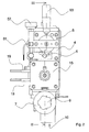
- Figure 1 is a perspective view of a glue dispensing apparatus;
- Figure 2 is a top view of the apparatus in Figure 1;
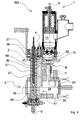
- Figure 3 is a schematic section taken along the plane III-III of the apparatus in Figure 1 in a first operating configuration;
- Figure 4 is a schematic section like the one in Figure 3 of the apparatus in Figure 1 in a second operating configuration;
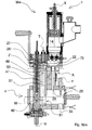
- Figure 5 is a schematic section like the one in Figure 3 of the apparatus in Figure 1 in a third operating configuration;
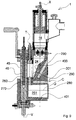
- Figure 5bis is a schematic section like the one in Figure 3 of the apparatus in Figure 1 in a fourth operating configuration;
- Figure 6 is a schematic section taken along the plane VI-VI of the apparatus in Figure 1;
- Figure 7 is a schematic longitudinal section of a second embodiment of the glue dispensing apparatus in Figure 1;
- Figure 8 is a schematic longitudinal section of a third embodiment of the glue dispensing apparatus in Figure 1;
- Figure 9 is a schematic longitudinal section of a fourth embodiment of the glue dispensing apparatus in Figure 1.
- With reference to Figures 1 to 6, a glue dispensing
apparatus 1 is shown arranged for dispensing a desired quantity of glue onto anelement 2 to be glued. - The
apparatus 1 is arranged for being associated with a working machine for machining wood or similar materials, which is not shown, such as, for example, an edgebanding machine or a squaring edgebanding machine. - In these working machines, the
apparatus 1 spreads a layer of glue onto belts, strips, lists or the like to be applied to edges of panels, or directly onto the edges of such panels. - The glue used is generally a glue in granular form, which is thermally meltable, which has to be suitably heated before being applied "hot" to the
elements 2 to be glued. - The
apparatus 1 comprises apre-melting unit 3, tank means 4, roller means 5 and doctor blade means 6. - The
pre-melting unit 3 is arranged for melting the glue and making the glue flowable, and comprises, as shown in Figure 3, containingmeans 7 having substantially funnel shape and defining a containingchamber 13 arranged for receiving and containing the glue, or a cleanser, in granular form. - The containing
means 7 comprises acover 8 arranged for being removed by means of ahandle 9 for manually loading the glue or the cleanser in granules into the containingchamber 13. - The containing
means 7 further comprises aside surface 53 in which aloading opening 10 is made that is connectable to a pneumatic loading device arranged for automatically loading the glue or the cleanser in granules into the containingchamber 13. - This pneumatic loading device, which is not shown, conveys the glue or the cleanser in granules in an air vein by means of the so-called "Venturi effect".
- In the
side surface 53, substantially at abottom portion 12 of the containingmeans 7, adischarging opening 11 is further made. - The
discharging opening 11 is positioned opposite theloading opening 10 and is arranged for enabling the glue or the cleanser in granules to pass from the containingchamber 13 to amelting chamber 14 of thepre-melting unit 3 in which the glue or the cleanser in granules are melted. - The
melting chamber 14, coated in non-stick material, is bounded by abox element 15 substantially having the shape of a parallelepipedon extending along a first axis X. - The
melting chamber 14 comprises afirst end portion 17 provided with apiston 16, for example drivable by pneumatic driving means, which is not shown. - The
piston 16, which is slidable in themelting chamber 14 along the first axis X, is arranged for pressing the glue or the cleanser, during a melting step of the glue or the cleanser, as will be better disclosed below. - The
melting chamber 14 further comprises a second end portion 18, opposite thefirst end portion 17, provided with first heating means 19, for example comprising a plurality of electric resistances. - The
melting chamber 14 further comprises casting channel means 20 operationally positioned above the first heating means 19 and defining a plurality ofinterstices 21 arranged for preventing the passage of glue or cleanser in the granular form, and for enabling the passage of glue or cleanser in a flowable state from themelting chamber 14 to acollecting chamber 22. - The
collecting chamber 22, which is provided with aconcave bottom surface 70 and arranged for receiving the glue or the cleanser that have been melted bypre-melting unit 3, is made in anend 71 of the tank means 4 on which thebox element 15 of thepre-melting unit 3 is fixed. - In this way, the
pre-melting unit 3 is integral with the tank means 4. - The tank means 4 comprises a supplying
chamber 24 arranged for supplying the roller means 2 with the glue. - In an embodiment of the invention, which is not shown, connecting means is provided, which comprises pipe means, arranged for connecting the
pre-melting unit 3 with the tank means 4. - In other words, in this embodiment the aforesaid connecting means is separated from, and mounted on, the tank means 4.
- The tank means 4 comprises a
feeding conduit 25 coated in non-stick material, extending along a second axis Y substantially parallel to the first axis X, and arranged for making the melted glue or the melted cleanser flow from thecollecting chamber 22 to the supplyingchamber 24. - The tank means 4 further comprises a
washing conduit 26, intersecting in an intersectingzone 28 thefeeding conduit 25. - The
washing conduit 26 extends along a third axis Z, that is transverse with respect to the first axis X, and is arranged for making possibly glue in the supplyingchamber 24 exit therefrom, as will be better disclosed below. - The tank means 4 further comprises shutter means 27 provided with a longitudinal passage 29.
- The shutter means 27 is substantially positioned at the
intersecting zone 28 and is rotatable, for example by pneumatic driving means, between a first working position A and a second working position B. - In the first working position A, shown in Figure 3, the shutter means 27 enables the glue to flow along the feeding
conduit 25 from the collectingchamber 22 to the supplyingchamber 24. - On the other hand, in the second working position B, shown in Figure 4, the shutter means 27 enables the glue in the supplying
chamber 24 to flow from the latter to anoutlet 100 of thewashing conduit 26 and from theoutlet 100 to the external environment, as will be better disclosed in below. - In an embodiment of the invention, which is not shown, the feeding
conduit 25 and thewashing conduit 26 are separated and respectively comprise first shutter means and second shutter means. - In this embodiment, the first shutter means comprises a first longitudinal passage and is movable between a first and a second operating position respectively to enable the glue to flow/prevent the glue from flowing from the collecting
chamber 22 to the supplyingchamber 24 whilst the second shutter means is provided with a second longitudinal passage and is also movable between a further first operating position and a further second operating position respectively to enable the glue to flow/prevent the glue from flowing from the supplyingchamber 24 to thewashing conduit 26. - The supplying
chamber 24, coated in non-stick material, is operationally positioned below the collectingchamber 22. - In this way, the melted glue or the melted cleanser can flow by gravity from the collecting
chamber 22 to the supplyingchamber 24. - The supplying
chamber 24 has a substantially parallelepipedon shape and extends along a fourth axis W substantially parallel to the third axis Z. - The supplying
chamber 24 further comprises abottom wall 32 extending substantially parallel to the fourth axis W and provided with awashing opening 33, for example threaded, closed by aclosing plug 34. The supplyingchamber 24 comprises afirst side wall 30 and asecond side wall 31, extending substantially perpendicularly with respect to the fourth axis W and facing each other. - The
first side wall 30 and thesecond side wall 31 are removable, in such a way as to enable easy access to the interior of the supplyingchamber 24 to enable the latter to be washed, as will be better disclosed below. - The supplying
chamber 24 further comprises second heating means 35 for heating the glue evenly and thus maintaining the glue flowable, for example comprising a plurality of electric resistances. - The supplying
chamber 24 is further provided with ahousing 36, extending substantially parallel to the second axis Y, arranged for receiving the doctor blade means 6. - The doctor blade means 6 is rotatable around, and extends along, a respective rotation axis T extending substantially parallel to the first axis X, so as to make a plurality of operating positions.
- The doctor blade means 6 is arranged for adjusting a quantity of glue to be transferred to an
external surface 45 of aroller 46 of the roller means 5, glue that is subsequently applied by the aforesaidexternal surface 45 to theelement 2 to be glued advancing along an advance direction S. - The doctor blade means 6 comprises an elongate
tubular element 37, having a substantially internally hollow cylindrical shape, extending along the rotation axis T. - The
tubular element 37 comprises agroove 54 extending along the rotation axis T and defining two facing and opposed portions that act respectively asfirst doctor blade 41 and second doctor blade 42 (Figure 6). - The
first doctor blade 41 and thesecond doctor blade 42 compriserespective abutment corners external surface 45 of theroller 46. - Inside the tubular element 37 a
gap 47 is further arranged for containing the glue and making the glue flow from the supplyingchamber 24 to the roller means 5 during a gluing step, or for making the glue flow from the supplyingchamber 24 to thewashing conduit 26 during a washing step, as will be better disclosed below. - The
gap 47 communicates respectively with thewashing conduit 26 and the supplyingchamber 24 through afirst opening 48 and asecond opening 49 made respectively in afirst end 50 and in asecond end 51 of the tubular element 37 (Figure 4) . - The
first opening 48 and thesecond opening 49 extend substantially parallel to the third axis Z and face respectively thewashing conduit 26 and the supplyingchamber 24. - The doctor blade means 6 further comprises adjusting means 52 arranged for adjusting a corresponding position of the
first doctor blade 41 and thesecond doctor blade 42 with respect to theroller 46. - In an embodiment of the invention, which is not shown, the doctor blade means 4 comprises a pair of doctor blades.
- The
roller 46, of known type, is arranged for rotating around a respective second rotation axis V, substantially parallel to the first rotation axis T, and by means of the knurled or roughexternal surface 45 for applying a layer of glue onto theelement 2 to be glued. - The
roller 46 is rotated by actuating means, not shown, both clockwise and anticlockwise in function of the type ofelements 2 to be glued. - For example, the
roller 46 rotates clockwise to glue strips or belts in the so-called "soft-forming" machining, whereas theroller 46 rotates anticlockwise to glue edges of panels or tables to be edgebanding in the so-called "straight" machining. - The
roller 46 further comprises aseat 57 extending along the second rotation axis V, arranged for receiving third heating means 56. - The third heating means 56, for example comprising an electric resistance, is arranged for maintaining the
external surface 45 of theroller 46 at a certain temperature to promote the "hot" application of the glue. - The
roller 46 further comprises ashank 59, for example toothed, arranged for coupling with a suitable drive means, which is not shown. - In this way, the
shank 59 acts as a rapid hooking/unhooking device for hooking/unhooking thedispensing apparatus 1 on the working machine. - The dispensing
apparatus 1 further compriseslevel sensors 60 inserted into and projecting inside the supplyingchamber 24, arranged for detecting the level of glue inside the latter and temperature control sensors 61 (Figure 1) arranged for detecting the temperature inside themelting chamber 14 and the supplyingchamber 24. - The dispensing
apparatus 1 further comprises first handle means 62 and second handle means 63 associated with and positioned on opposite parts with respect to the supplyingchamber 24, said first handle means 62 and said second handle means 63 being arranged for facilitating the lifting thereof. - With particular reference to Figures 3, 4 and 5, the operation of the
glue dispensing apparatus 1 is disclosed below. - In Figure 3 the
dispensing apparatus 1 is shown in a first operating configuration W1, in which thedispensing apparatus 1 is arranged for dispensing a desired quantity of glue onto theelement 2 to be glued. - In the first operating configuration W1, the
melting chamber 14 is at least partially filled with the glue in granules coming from the containingchamber 13. - Inside the
melting chamber 14 the glue is heated to a melting temperature by the first heating means 19 and is simultaneously pressed by thepiston 16. - In this way, the glue, in melted state, passes through the
interstices 21 from themelting chamber 14 to the collectingchamber 22. - In the collecting
chamber 22 the glue is conveyed from the bottomconcave surface 70 to thefeeding conduit 25. - As in the first operating configuration W1 the shutter means 27 is positioned in the first working position A, the melted glue flows along the feeding
conduit 25 from the collectingchamber 22 to the supplyingchamber 24. - Once the supplying
chamber 24 and thegap 47 have been completely filled with melted glue, and after the doctor blade means 6 has been positioned in a desired operating position, theroller 46 is rotated, which by means of theexternal surface 45 dispenses a layer of glue onto theelement 2 to be glued. - In Figure 4 the
dispensing apparatus 1 is shown in a second operating configuration W2, in which it is possible to remove the glue from the supplyingchamber 24. - In the second operating configuration W2 the shutter means 27 is positioned in the second working position B.
- In order to remove the glue from the supplying
chamber 24 it is sufficient to remove theclosing plug 34 from thewashing opening 33 and rotate theroller 46. - In this way, a prevalent quantity of glue exits from the
closing plug 34, whilst a residual quantity of glue in the supplyingchamber 24 flows from the latter to theoutlet 100 of thewashing conduit 26 along thegap 47 through the effect of the rotation of theroller 46 and of the particular conformation of the suitably knurled or roughexternal surface 45, suitable for retaining and conveying the glue. - In Figure 5 the
dispensing apparatus 1 is shown in a third operating configuration W3, in which it is possible to perform thorough cleaning of the supplyingchamber 24 can be carried out. - In the third operating configuration W3, the shutter means 27 is positioned in the second working position B and the
first wall 30 and thesecond wall 31 have been removed from the supplyingchamber 24. - In order to perform thorough cleaning of the supplying
chamber 24, i.e. in order to remove the solidified glue residues inside the supplying chamber, it is sufficient to unscrew theclosing plug 34 to evacuate the residual glue in the supplyingchamber 24, remove thefirst side wall 31 and thesecond side wall 31 and insert into the supplyingchamber 24 suitable cleaning means, which is not shown, for example comprising cleaning brush means. - In Figure 5bis the dispensing
apparatus 1 is shown in a fourth operating configuration W4, in which it is possible to perform the washing of the supplyingchamber 24 by means of the cleanser in granules. - In the fourth operating configuration W4 the shutter means 27 is positioned in the first working position A and the
closing plug 34 has been removed from thewashing opening 33. - The supplying
chamber 24 is washed after the glue in the supplyingchamber 24 and in thegap 47 has been suitably removed in the manner disclosed above. - The cleanser in granules is introduced into the
melting chamber 14 through the containingchamber 13 to perform washing of the supplyingchamber 34. - Inside the
melting chamber 14 the cleanser is heated to a melting temperature by the first heating means 19 and is simultaneously pressed by thepiston 16. - In this way, the cleanser, in melted state, passes through the
interstices 21 from themelting chamber 14 to the collectingchamber 22. - In the collecting
chamber 22 the cleanser is conveyed from theconcave bottom surface 70 to thefeeding conduit 25. - As in the fourth operating configuration W4 the shutter means 27 is positioned in the first working position A, the melted cleanser flows along the feeding
conduit 25 from the collectingchamber 22 to the supplyingchamber 24 and from the latter exits through thewashing opening 33. - With reference to Figure 7 a second embodiment of the
glue dispensing apparatus 1 is shown. - In this embodiment, operatively substantially similar to the embodiment disclosed in the Figures 1 to 6, the supplying
chamber 24 comprises anintermediate portion 200 which has a substantially parallelepipedon shape and extends along the second axis Y. - In this embodiment, furthermore, the
bottom wall 32, substantially positioned at theintermediate portion 200, is removable, so as to enable an easy access to the interior of the supplyingchamber 24 to enable the supplyingchamber 24 to be washed, as previously disclosed. - In particular, in a washing step, the
plug 34 is at first removed for causing a prevalent quantity of glue to flow out and subsequently thebottom wall 32 is removed for causing a remaining quantity of glue to flow out. - With reference to Figure 8 a third embodiment of the
glue dispensing apparatus 1 is shown. - In this embodiment, the glue or the cleanser flow directly from the
melting chamber 14 into the supplyingchamber 24. - In this embodiment, furthermore, the supplying
chamber 24 comprises amain portion 300 having substantially shape of a parallelepipedon and extending substantially parallel to the first axis X. - The
main portion 300 comprises afeeding opening 301 for feeding the glue to theroller 46, thefeeding opening 301 having almost equal height with respect to a portion of theexternal surface 45 arranged for receiving the glue. - In this embodiment, furthermore, the
bottom wall 32, positioned substantially at themain portion 300, is removable, so as to allow an easy access to the interior of the supplyingchamber 24 to enable the supplyingchamber 24 to be cleaned, as disclosed previously. - In particular, in a washing step the
plug 34 is first of all removed to cause a prevalent quantity of glue to flow out and subsequently thebottom wall 32 is removed to cause a remaining quantity of glue to flow out. - With reference to Figure 9 a fourth embodiment of the
glue dispensing apparatus 1 is shown. - In this embodiment, the melted glue or the melted cleanser flow directly from the
melting chamber 14 into the supplyingchamber 24. - In this embodiment, the supplying
chamber 24, having substantially shape of upside-down truncated cone, comprises awall 400, inclined with respect to the first axis X, arranged for directing the glue to theroller 46. - Also in this embodiment, the
feeding opening 301 for feeding the glue to theroller 46 has an almost equal height with respect to the portion of theexternal surface 45 arranged for receiving the glue. - In this embodiment, the tank means 4 comprises a connecting
conduit 260 arranged for connecting the supplyingchamber 24 with a dischargingchamber 251 arranged for causing the glue to flow out of the supplyingchamber 24. - The discharging
chamber 251, positioned below the supplyingchamber 24, extends along a fifth axis Q substantially perpendicular with respect to the first axis X and has substantially shape of a truncated cone. - In other words, the discharging
chamber 251 is defined bywalls 401 diverging in the advancing direction of the glue. - The discharging
chamber 251 further comprises afurther wall 280 removably associated with the unloadingchamber 251, so as to allow an easy access to the interior of the dischargingchamber 251 to enable the dischargingchamber 251 to be washed. - In this embodiment, further shutter means 270 is further provided, associated with the connecting
conduit 260, and movable between a further first working position C, and a further second working position, not shown, in which the further shutter means 270 respectively enables/prevents the glue, or the cleanser, from flowing along the connectingconduit 260 from the supplyingchamber 24 to the dischargingchamber 251. - At last, in this embodiment,
further seats 290 are provided, positioned between the supplyingchamber 24 and the dischargingchamber 251, arranged for receiving the second heating means 35, not represented. - It is to be noticed that, owing to the invention, a particularly compact
glue dispensing apparatus 1 can be obtained. - In fact, the
pre-melting unit 3 is mounted directly on the tank means 4; in other words thepre-melting unit 3 is integral with the tank means 4. - This further enables the thermal efficiency of the
dispensing apparatus 1 to be improved. - In fact, the first heating means 19 of the
pre-melting unit 3 can be used both for melting the glue in themelting chamber 14 and for heating at least a portion of the tank means 4, so that the glue is maintained flowable at the interior of the tank means 4. - This enables the number of electric resistances of the tank means 4, and consequently of the
dispensing apparatus 1, to be reduced with consequent economic savings. - It is still to be noticed that, as in the
apparatus 1 disclosed above, the glue flows from thepre-melting unit 3 to the tank means 4 inside the latter. - This enables, on the one hand, undesired cooling of the glue to be limited and consequently the thermal efficiency of the
apparatus 1 to be improved, and, on the other hand, contamination of the glue with possible dirt present near the dispensingapparatus 1 to be eliminated. - It is further to be noticed, as owing to the
washing opening 33, thefirst side wall 30, thesecond side wall 31 and/or theremovable bottom wall 32 and/or the dischargingchamber 251 provided with thefurther wall 280, the tank means 4 can be washed quickly and efficiently, so as to enable a fast and efficient substitution of the type and/or the colour of the glue.
Claims (30)
- Glue dispensing apparatus for dispensing a desired quantity of glue onto an element (2) to be glued, comprising a pre-melting unit (3) for melting said glue and tank means (4) for receiving said glue from said pre-melting unit (3), characterized in that said pre-melting unit (3) is fixed to said tank means (4).
- Apparatus according to claim 1, wherein said tank means (4) comprises a supplying chamber (24) arranged for supplying glue dispensing means (5) with said glue.
- Apparatus according to claim 2, wherein said supplying chamber (24) comprises a wall (400) inclined with respect to a substantially vertical axis (X).
- Apparatus according to any preceding claim, wherein said tank means comprises a collecting chamber (12) arranged for receiving said glue from said pre-melting unit (3).
- Apparatus according to claim 4, wherein said collecting chamber (22) faces a melting chamber (14) of said pre-melting unit (3) arranged for melting said glue.
- Apparatus according to claim 4, or 5, wherein said collecting chamber (22) comprises a substantially concave bottom surface (70).
- Apparatus according to any of claims 4 to 6, as claim 4 is appended to claim 2, or 3, wherein said tank means (4) comprises feeding conduit means (25) arranged for exiting said glue from said collecting chamber (22) to said supplying chamber (24).
- Apparatus according to claim 7, wherein said tank means (4) comprises first shutter means associated with said feeding conduit means (25) and movable between a first operating position and a second operating position respectively for enabling/preventing said glue from flowing from said collecting chamber (22) to said supplying chamber (24).
- Apparatus according to any one of claims 2 to 8, as claim 4 is appended to claim 2, or 3, wherein said tank means (4) comprises washing conduit means (26) arranged for exiting said glue from said supplying chamber (24).
- Apparatus according to claim 9, wherein said tank means (4) comprises second shutter means associated with said washing conduit means (26) and movable between a further first operating position and a further second operating position respectively for enabling/preventing said glue exiting said supplying chamber (24).
- Apparatus according to claim 9, or 10, wherein said feeding conduit means (25) intersects said washing conduit means (26) in an intersecting zone (28) of said tank means (4).
- Apparatus according to claim 11, wherein said tank means (4) comprises shutter means (27), positioned substantially at said intersecting zone (28), and movable between a first working position (A), in which said shutter means (27) enables said glue to flow along said feeding conduit means (25) from said collecting chamber (22) to said supplying chamber (24), and a second working position (B), in which said shutter means (27) enables said glue to flow from said supplying chamber (24) to an outlet (100) of said washing conduit means (26).
- Apparatus according to any preceding claim, and comprising opening means (30, 31, 32, 33, 251, 280), associated with said tank means (4), and arranged for enabling said tank means (4) to be washed.
- Apparatus according to claim 13, wherein said opening means (30, 31, 33, 251, 280) comprises wall means (30, 31, 32) removably associated with said supplying chamber (24).
- Apparatus according to claim 14, wherein said wall means (30, 31, 32) comprises a first wall (30) and a second wall (31) of said supplying chamber (24).
- Apparatus according to claim 15, wherein said first wall (30) and said second wall (31) face each other.
- Apparatus according to any one of claims 14 to 16, wherein said wall means (30, 31, 32) comprises a bottom wall (32) of said supplying chamber (24).
- Apparatus according to any one of claims 13 to 17, wherein said opening means (30, 31, 33, 251, 280) comprises a washing opening (33) arranged for exiting said glue from said tank means (4).
- Apparatus according to claim 18, wherein said washing opening (33) is made in said bottom wall (32).
- Apparatus according to claim 18, or 19, and comprising plug means (34) removably associated with said washing opening (33).
- Apparatus according to claim 13, as claim 13 is appended to claim 2, or 3, wherein said opening means (30, 31, 33, 251, 280) comprises a discharging chamber (251) arranged for receiving said glue and exiting said glue from said supplying chamber (24).
- Apparatus according to claim 21, wherein said discharging chamber (251) is defined by diverging walls (401).
- Apparatus according to claim 21, or 22, wherein said tank means (4) comprises a connecting conduit (260) arranged for connecting said discharging chamber (251) with said supplying chamber (24).
- Apparatus according to claim 23, wherein said tank means (4) comprises further shutter means (270), associated with said connecting conduit (260), and movable between a further first working position (C), and a further second working position, wherein said further shutter means (270) respectively enables/prevents said glue from flowing along said connecting conduit (260) from said supplying chamber (24) to said discharging chamber (251).
- Apparatus according to any one of claims 21 to 24, wherein said opening means (30, 31, 33, 251, 280) comprises further wall means (280) removably associated with said discharging chamber (251).
- Apparatus according to any preceding claim, and comprising rapid hooking/unhooking means (59) for enabling said apparatus (1) to be rapidly hooked/unhooked to/from a working machine.
- Apparatus according to claim 26, wherein said rapid hooking/unhooking means comprises shank means (59).
- Apparatus according to any preceding claim, and comprising pneumatic loading means arranged for loading said glue in granular form into said pre-melting unit (3).
- Apparatus according to any preceding claim, and comprising lifting means (62, 63) arranged for facilitating said apparatus (1) to be lifted.
- Apparatus according to claim 29, wherein said lifting means comprises handle means (62, 63).
Applications Claiming Priority (1)
| Application Number | Priority Date | Filing Date | Title |
|---|---|---|---|
| ITMO20060262 ITMO20060262A1 (en) | 2006-08-28 | 2006-08-28 | DISTRIBUTOR DEVICE OF GLUE |
Publications (2)
| Publication Number | Publication Date |
|---|---|
| EP1894636A2 true EP1894636A2 (en) | 2008-03-05 |
| EP1894636A3 EP1894636A3 (en) | 2011-01-12 |
Family
ID=38610509
Family Applications (1)
| Application Number | Title | Priority Date | Filing Date |
|---|---|---|---|
| EP20070112096 Ceased EP1894636A3 (en) | 2006-08-28 | 2007-07-09 | Glue dispensing apparatus |
Country Status (2)
| Country | Link |
|---|---|
| EP (1) | EP1894636A3 (en) |
| IT (1) | ITMO20060262A1 (en) |
Cited By (3)
| Publication number | Priority date | Publication date | Assignee | Title |
|---|---|---|---|---|
| CN103316814A (en) * | 2013-06-06 | 2013-09-25 | 苏州阿斯兰自动化科技有限公司 | Automatic glue printing mechanism |
| CN108246559A (en) * | 2018-04-03 | 2018-07-06 | 佛山市豪伟德机械有限公司 | A kind of glue spreading apparatus of sealing |
| CN112497839A (en) * | 2020-11-17 | 2021-03-16 | 萍乡市时代工艺包装有限公司 | Automatic gluing machine for packaging box production and control method |
Citations (3)
| Publication number | Priority date | Publication date | Assignee | Title |
|---|---|---|---|---|
| US2809772A (en) | 1955-05-02 | 1957-10-15 | Kamborian Jacob S | Apparatus for melting and dispensing thermoplastic adhesive |
| US3773069A (en) | 1971-02-03 | 1973-11-20 | Usm Corp | Apparatus for dispensing heat softenable adhesive initially in granule form |
| EP1243345A2 (en) * | 2001-03-19 | 2002-09-25 | PAUL OTT GmbH | Edge-gluing machine |
Family Cites Families (2)
| Publication number | Priority date | Publication date | Assignee | Title |
|---|---|---|---|---|
| US2868420A (en) * | 1957-10-30 | 1959-01-13 | Kamborian Jacob S | Apparatus for melting and dispensing thermoplastic adhesive |
| US4850425A (en) * | 1987-04-06 | 1989-07-25 | Anderson Steven R | Apparatus for preparing adhesives for application |
-
2006
- 2006-08-28 IT ITMO20060262 patent/ITMO20060262A1/en unknown
-
2007
- 2007-07-09 EP EP20070112096 patent/EP1894636A3/en not_active Ceased
Patent Citations (3)
| Publication number | Priority date | Publication date | Assignee | Title |
|---|---|---|---|---|
| US2809772A (en) | 1955-05-02 | 1957-10-15 | Kamborian Jacob S | Apparatus for melting and dispensing thermoplastic adhesive |
| US3773069A (en) | 1971-02-03 | 1973-11-20 | Usm Corp | Apparatus for dispensing heat softenable adhesive initially in granule form |
| EP1243345A2 (en) * | 2001-03-19 | 2002-09-25 | PAUL OTT GmbH | Edge-gluing machine |
Cited By (4)
| Publication number | Priority date | Publication date | Assignee | Title |
|---|---|---|---|---|
| CN103316814A (en) * | 2013-06-06 | 2013-09-25 | 苏州阿斯兰自动化科技有限公司 | Automatic glue printing mechanism |
| CN108246559A (en) * | 2018-04-03 | 2018-07-06 | 佛山市豪伟德机械有限公司 | A kind of glue spreading apparatus of sealing |
| CN108246559B (en) * | 2018-04-03 | 2023-12-15 | 广东豪德数控装备股份有限公司 | Sealed rubber coating device |
| CN112497839A (en) * | 2020-11-17 | 2021-03-16 | 萍乡市时代工艺包装有限公司 | Automatic gluing machine for packaging box production and control method |
Also Published As
| Publication number | Publication date |
|---|---|
| ITMO20060262A1 (en) | 2008-02-29 |
| EP1894636A3 (en) | 2011-01-12 |
Similar Documents
| Publication | Publication Date | Title |
|---|---|---|
| EP1894689B1 (en) | Glue dispensing apparatus | |
| CN104890906B (en) | Full-automatic quantitative carbon package packaging machine | |
| TW201341062A (en) | Melting system | |
| KR101764620B1 (en) | coated device of brazing ring fused-flux | |
| TW201341296A (en) | Reversible flow inducer | |
| SE441765B (en) | DEVICE FOR REMOVAL CONTAINER OF ADHESIVE AND HIGH-viscous masses of adhesive nature | |
| JP4634726B2 (en) | Method, apparatus and system for controlling and dispensing prepared flowable materials | |
| CN213673664U (en) | Feeding device for grinding wheel production | |
| CN118317838A (en) | Edge banding machine with pneumatic adhesive granulate delivery | |
| KR20110073554A (en) | Case sealer with integral hot melt dispensing system | |
| EP2332708B1 (en) | Apparatus for dispensing meltable material | |
| CN109757536B (en) | Automatic spring pancake processing machine | |
| EP3653308B1 (en) | Fusing device and method for using said fusing device | |
| EP2162236B1 (en) | Glue spreading apparatus | |
| CN120840083A (en) | 3D printing post-processing device and 3D printing system | |
| ITMO20060262A1 (en) | DISTRIBUTOR DEVICE OF GLUE | |
| CN108788013A (en) | A kind of sand casting system with dispensing and sand mold finished product clearing function | |
| CN113490550A (en) | Apparatus for providing adhesive | |
| GB1599856A (en) | Mixing apparatus | |
| JPH06178957A (en) | Roll coater | |
| CN221413711U (en) | Glue spreader | |
| SE463720B (en) | DEVICE FOR THE PREPARATION OF A MIXTURE OF PRECIOUS STONE MATERIAL AND ASPHALT BINDING MATERIALS FOR THE PREPARATION OF DAMAGE TO ASPALT COATINGS | |
| JP5634915B2 (en) | Paste applicator for glue bag | |
| CN223111481U (en) | A powder spreader | |
| CN217497641U (en) | Belt conveyor tail self-moving cleaning device |
Legal Events
| Date | Code | Title | Description |
|---|---|---|---|
| PUAI | Public reference made under article 153(3) epc to a published international application that has entered the european phase |
Free format text: ORIGINAL CODE: 0009012 |
|
| AK | Designated contracting states |
Kind code of ref document: A2 Designated state(s): AT BE BG CH CY CZ DE DK EE ES FI FR GB GR HU IE IS IT LI LT LU LV MC MT NL PL PT RO SE SI SK TR |
|
| AX | Request for extension of the european patent |
Extension state: AL BA HR MK YU |
|
| RIC1 | Information provided on ipc code assigned before grant |
Ipc: B29B 13/02 20060101ALI20100806BHEP Ipc: B05C 11/10 20060101AFI20071026BHEP |
|
| PUAL | Search report despatched |
Free format text: ORIGINAL CODE: 0009013 |
|
| AK | Designated contracting states |
Kind code of ref document: A3 Designated state(s): AT BE BG CH CY CZ DE DK EE ES FI FR GB GR HU IE IS IT LI LT LU LV MC MT NL PL PT RO SE SI SK TR |
|
| AX | Request for extension of the european patent |
Extension state: AL BA HR MK RS |
|
| 17P | Request for examination filed |
Effective date: 20110712 |
|
| AKX | Designation fees paid |
Designated state(s): AT DE ES |
|
| 17Q | First examination report despatched |
Effective date: 20121129 |
|
| STAA | Information on the status of an ep patent application or granted ep patent |
Free format text: STATUS: THE APPLICATION HAS BEEN REFUSED |
|
| 18R | Application refused |
Effective date: 20150608 |