EP1894635A1 - Verfahren zur herstellung eines zweiphasigen gas-tropfen-strahls und vorrichtung zur durchführung des verfahrens - Google Patents
Verfahren zur herstellung eines zweiphasigen gas-tropfen-strahls und vorrichtung zur durchführung des verfahrens Download PDFInfo
- Publication number
- EP1894635A1 EP1894635A1 EP06757963A EP06757963A EP1894635A1 EP 1894635 A1 EP1894635 A1 EP 1894635A1 EP 06757963 A EP06757963 A EP 06757963A EP 06757963 A EP06757963 A EP 06757963A EP 1894635 A1 EP1894635 A1 EP 1894635A1
- Authority
- EP
- European Patent Office
- Prior art keywords
- gas
- drop
- jet
- creating
- nozzle
- Prior art date
- Legal status (The legal status is an assumption and is not a legal conclusion. Google has not performed a legal analysis and makes no representation as to the accuracy of the status listed.)
- Withdrawn
Links
Images

Classifications
-
- B—PERFORMING OPERATIONS; TRANSPORTING
- B05—SPRAYING OR ATOMISING IN GENERAL; APPLYING FLUENT MATERIALS TO SURFACES, IN GENERAL
- B05B—SPRAYING APPARATUS; ATOMISING APPARATUS; NOZZLES
- B05B7/00—Spraying apparatus for discharge of liquids or other fluent materials from two or more sources, e.g. of liquid and air, of powder and gas
- B05B7/02—Spray pistols; Apparatus for discharge
- B05B7/04—Spray pistols; Apparatus for discharge with arrangements for mixing liquids or other fluent materials before discharge
- B05B7/0416—Spray pistols; Apparatus for discharge with arrangements for mixing liquids or other fluent materials before discharge with arrangements for mixing one gas and one liquid
-
- B—PERFORMING OPERATIONS; TRANSPORTING
- B05—SPRAYING OR ATOMISING IN GENERAL; APPLYING FLUENT MATERIALS TO SURFACES, IN GENERAL
- B05B—SPRAYING APPARATUS; ATOMISING APPARATUS; NOZZLES
- B05B1/00—Nozzles, spray heads or other outlets, with or without auxiliary devices such as valves, heating means
- B05B1/34—Nozzles, spray heads or other outlets, with or without auxiliary devices such as valves, heating means designed to influence the nature of flow of the liquid or other fluent material, e.g. to produce swirl
-
- A—HUMAN NECESSITIES
- A62—LIFE-SAVING; FIRE-FIGHTING
- A62C—FIRE-FIGHTING
- A62C31/00—Delivery of fire-extinguishing material
- A62C31/02—Nozzles specially adapted for fire-extinguishing
- A62C31/05—Nozzles specially adapted for fire-extinguishing with two or more outlets
-
- A—HUMAN NECESSITIES
- A62—LIFE-SAVING; FIRE-FIGHTING
- A62C—FIRE-FIGHTING
- A62C31/00—Delivery of fire-extinguishing material
- A62C31/02—Nozzles specially adapted for fire-extinguishing
- A62C31/12—Nozzles specially adapted for fire-extinguishing for delivering foam or atomised foam
-
- B—PERFORMING OPERATIONS; TRANSPORTING
- B05—SPRAYING OR ATOMISING IN GENERAL; APPLYING FLUENT MATERIALS TO SURFACES, IN GENERAL
- B05B—SPRAYING APPARATUS; ATOMISING APPARATUS; NOZZLES
- B05B7/00—Spraying apparatus for discharge of liquids or other fluent materials from two or more sources, e.g. of liquid and air, of powder and gas
- B05B7/02—Spray pistols; Apparatus for discharge
- B05B7/06—Spray pistols; Apparatus for discharge with at least one outlet orifice surrounding another approximately in the same plane
Definitions
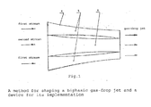
- a method for shaping a biphasic gas-drop jet and a device for its implementation is a method for shaping a biphasic gas-drop jet and a device for its implementation.
- the proposed group of inventions relates to technique for obtaining highly concentrated jets, featuring a long range and finely dispersed structure of drops.
- Such jets may be used in fire extinguishing equipment, in agriculture for watering and in other fields where finely dispersed and long-range gas-drop jets are required.
- the method most close from the point of view of technical essence to the offered engineering solution is the method for creating a gas-drop jet, including supply of liquid and gas stream, dispersion of liquid, mixing the dispersed liquid with the gas stream and acceleration of the obtained biphasic gas-drop stream (RF Patent N° 2243036 , Cl. B05B 7/10, 2002).
- the known method has the following drawbacks:
- the closest engineering solution to the proposed one is the device for realization of a method of creation of the gas-drop jet, including a chamber for shaping a biphasic gas-drop stream with inlets for supplying liquid and gas and a gas-dynamic nozzle connected to it (RF Patent N° 2243036 , Cl. B05B 7/10, 2002) .
- the known design has a drawback of decrease in gas-drop jet range because of a dilative shape of the nozzle channel in its outlet portion since the emanating jet has radial components that improves mixing the jet with the environment and its promotes its faster braking.
- the aims of the proposed group of inventions are as follows: extending the jet range due to more rational use of the energy of the liquid and its utmost transformation in kinetic energy of ordered motion due to design features of the device.
- the technical result in the proposed invention is reached by creating a method for shaping a gas-drop jet including delivery of liquid and gas stream, dispersion of liquid, mixing the dispersed liquid with the gas stream and acceleration of the resulting biphasic gas-drop stream where, according to the invention, a biphasic gas-drop stream after mixing is divided, at least, to two streams and is accelerated separately in one direction till obtaining identical values of output speed and pressure at the nozzle outlet.
- a device for the creating a gas-drop jet including a chamber for shaping a biphasic gas-drop stream with inlets for supplying liquid and gas and a gas-dynamic nozzle connected to it where, according to the invention, the nozzle is made as at least, double-ring, coaxial device, and each ring has a profiled channel designed for creating identical values of output speed and pressure at the nozzle outlet, and the channels are unidirectional.
- Fig. 1 the installation diagram of the device for implementing the method for creating gas-drop jet with coaxial, e.g., a double-ring nozzle is shown.
- the device for creating a gas-drop jet includes the chamber 1 for shaping a biphasic gas-drop stream with inlets for supplying liquid 2 and gas 3, a multi-ring coaxial gas-dynamic nozzle 4 connected to the said device.
- the multi-ring coaxial gas dynamic nozzle 4 consists of two (or more) unidirectional channels: the external channel 5 and 6 of the internal channel 6 and is designed for accelerating the gas-drop stream having a disperse structure and obtaining a gas-drop jet.
- the multi-ring coaxial gas-dynamic nozzle 4 may be double-ring or multi-ring for compacting the jet.
- the inlets for supplying liquid 2 and gas 3 are connected to devices for supplying liquid 7 and gas 8.
- the proposed method for creating a gas-drop jet is implemented as follows:
- the working media gas (e.g. air) and water are supplied to the chamber for shaping the biphasic gas-drop stream 1 where the liquid is dispersed and a biphasic stream of the gas-drop structure is created.
- gas e.g. air
- water are supplied to the chamber for shaping the biphasic gas-drop stream 1 where the liquid is dispersed and a biphasic stream of the gas-drop structure is created.
- the biphasic gas-drop stream shaped in the chamber for shaping the biphasic gas-drop stream is divided, for example, to two (or more) streams, each of those streams is supplied to the corresponding channel of the nozzle 4 where they are accelerated in one direction for getting identical speed and pressure at the nozzle outlet.
- the first stream is supplied to the external ring 5, the second stream is supplied to the internal ring or circle 6.
- the gas-drop jet having minimal radial components is shaped. This allows to reduce the radial expansion of the jet, or to compact it. In both cases, the jet range extends.
- a turboblower station may be used as a gas source.
- the turboblower station may be equipped with a pump for maintaining the required parameters of the liquid.
- the proposed device may be mobile if necessary.
- a vehicle for example, a car, a helicopter, an aircraft, water transport. (not shown in the figure).
- the parameters of the device for implementing the proposed method such as pressure P CH in the chamber for shaping the biphasic gas-drop stream 1, throughput weight of liquid G L and gas G G ; initial pressure of fluid P L and distribution of throughput between the streams are to be chosen according to the condition of obtaining the set extent of jet reach.
- the proposed device is set to a starting position.
- the multi-ring coaxial gas-dynamic nozzle 4 with the stream of gas-drop structure is directed towards the target object where the gas-drop jet is to be supplied.
- the flow of biphasic stream was distributed between the rings or circles as one to five relationship (internal circle to the external ring).
- the jet range as compared to that of the single-circle nozzle design extends under the given conditions by 15%.
- the jet range extended by 15% as compared to the prototype under equal boundary conditions.
- test results confirm the possibility of implementation of the proposed method for creating a gas-drop jet and the device for its implementation, and the possibility of achievement of the technical result consisting in raising the efficiency of the gas-drop jet.
- Use of the group of inventions in fire fighting equipment is the most effective for suppressing fires in the sites where the use of minimum quantity of fluid with maximum efficiency (for minimizing the damage from the process of extinguishing), in climate systems for agriculture, medicine, environment protection, etc.
Landscapes
- Health & Medical Sciences (AREA)
- Public Health (AREA)
- Business, Economics & Management (AREA)
- Emergency Management (AREA)
- Nozzles (AREA)
- Fire-Extinguishing By Fire Departments, And Fire-Extinguishing Equipment And Control Thereof (AREA)
Applications Claiming Priority (2)
| Application Number | Priority Date | Filing Date | Title |
|---|---|---|---|
| RU2005115508 | 2005-05-23 | ||
| PCT/RU2006/000258 WO2006137755A1 (fr) | 2005-05-23 | 2006-05-23 | Procede permettant de produire un jet de gaz-gouttelettes diphasique et dispositif destine a sa mise en oeuvre |
Publications (2)
| Publication Number | Publication Date |
|---|---|
| EP1894635A1 true EP1894635A1 (de) | 2008-03-05 |
| EP1894635A4 EP1894635A4 (de) | 2009-06-10 |
Family
ID=37570700
Family Applications (1)
| Application Number | Title | Priority Date | Filing Date |
|---|---|---|---|
| EP06757963A Withdrawn EP1894635A4 (de) | 2005-05-23 | 2006-05-23 | Verfahren zur herstellung eines zweiphasigen gas-tropfen-strahls und vorrichtung zur durchführung des verfahrens |
Country Status (2)
| Country | Link |
|---|---|
| EP (1) | EP1894635A4 (de) |
| WO (1) | WO2006137755A1 (de) |
Cited By (2)
| Publication number | Priority date | Publication date | Assignee | Title |
|---|---|---|---|---|
| CN103028217A (zh) * | 2011-09-29 | 2013-04-10 | 上海磊诺工业气体有限公司 | 嵌装式气体喷嘴 |
| JP2013081924A (ja) * | 2011-10-12 | 2013-05-09 | Jfe Engineering Corp | 噴霧ノズル、該噴霧ノズルを用いた流体微粒化装置 |
Families Citing this family (1)
| Publication number | Priority date | Publication date | Assignee | Title |
|---|---|---|---|---|
| CN101357255B (zh) * | 2008-09-11 | 2011-09-14 | 中国科学技术大学 | 渐开线弧形喷口消防灭火喷洒头 |
Family Cites Families (6)
| Publication number | Priority date | Publication date | Assignee | Title |
|---|---|---|---|---|
| DD233490A1 (de) * | 1985-01-02 | 1986-03-05 | Tech Hochschule Magdeburg Otto | Verfahren und vorrichtung zum aufbringen eines loeschmittels |
| GB8724973D0 (en) * | 1987-10-24 | 1987-11-25 | Bp Oil Ltd | Fire fighting |
| RU2107554C1 (ru) * | 1996-07-08 | 1998-03-27 | Научно-исследовательский институт низких температур при Московском государственном авиационном институте (техническом университете) | Способ создания газокапельной струи, установка для его осуществления и сопло для создания газокапельной струи |
| RU2121390C1 (ru) * | 1997-05-14 | 1998-11-10 | Научно-исследовательский институт низких температур при МАИ (Московском государственном авиационном институте - техническом университете) | Установка для пожаротушения |
| FR2766108B1 (fr) * | 1997-07-17 | 1999-10-15 | France Etat | Dispositif de generation d'un fluide diphasique |
| RU2243036C1 (ru) * | 2003-04-17 | 2004-12-27 | Закрытое акционерное общество "СИЛЭН" | Способ создания газокапельной струи и устройство для его выполнения |
-
2006
- 2006-05-23 EP EP06757963A patent/EP1894635A4/de not_active Withdrawn
- 2006-05-23 WO PCT/RU2006/000258 patent/WO2006137755A1/ru not_active Ceased
Cited By (2)
| Publication number | Priority date | Publication date | Assignee | Title |
|---|---|---|---|---|
| CN103028217A (zh) * | 2011-09-29 | 2013-04-10 | 上海磊诺工业气体有限公司 | 嵌装式气体喷嘴 |
| JP2013081924A (ja) * | 2011-10-12 | 2013-05-09 | Jfe Engineering Corp | 噴霧ノズル、該噴霧ノズルを用いた流体微粒化装置 |
Also Published As
| Publication number | Publication date |
|---|---|
| EP1894635A4 (de) | 2009-06-10 |
| WO2006137755A1 (fr) | 2006-12-28 |
Similar Documents
| Publication | Publication Date | Title |
|---|---|---|
| RU2107554C1 (ru) | Способ создания газокапельной струи, установка для его осуществления и сопло для создания газокапельной струи | |
| CN1236858C (zh) | 液体喷雾器 | |
| AU2021212034B2 (en) | Method and system for reducing drag in a vehicle | |
| JP5662655B2 (ja) | ノズル | |
| US4915300A (en) | High pressure mixing and spray nozzle apparatus and method | |
| CN101936310A (zh) | 无扇叶风扇 | |
| US20230192203A1 (en) | Active drag-reduction system and a method of reducing drag experienced by a vehicle | |
| JP2010247133A (ja) | 二流体ノズル | |
| CN101985949A (zh) | 无叶风扇装置 | |
| RU2243036C1 (ru) | Способ создания газокапельной струи и устройство для его выполнения | |
| US4473186A (en) | Method and apparatus for spraying | |
| US4809911A (en) | High pressure mixing and spray nozzle apparatus and method | |
| EP1894635A1 (de) | Verfahren zur herstellung eines zweiphasigen gas-tropfen-strahls und vorrichtung zur durchführung des verfahrens | |
| RU2252080C1 (ru) | Способ создания газокапельной двухфазной струи и устройство для его осуществления | |
| RU2258567C1 (ru) | Распылитель жидкости | |
| RU2432212C1 (ru) | Устройство создания дальнобойной газокапельной струи | |
| RU2556672C1 (ru) | Способ создания газокапельной струи и устройство для его выполнения | |
| RU57151U1 (ru) | Устройство для формирования двухфазной газокапельной струи | |
| RU2482926C1 (ru) | Устройство создания дальнобойной газокапельной струи | |
| CN102384104A (zh) | 轴流叶轮 | |
| CN214515563U (zh) | 超音速气雾化装置及超音速气雾化器 | |
| EP2599970A2 (de) | Reduktion von Aufheizungseffekten eines aufprallenden Abgasstrahls | |
| RU2487763C1 (ru) | Устройство создания газокапельной струи | |
| RU2492936C1 (ru) | Способ формирования газокапельной струи | |
| RU124891U1 (ru) | Насадок для пожаротушения |
Legal Events
| Date | Code | Title | Description |
|---|---|---|---|
| PUAI | Public reference made under article 153(3) epc to a published international application that has entered the european phase |
Free format text: ORIGINAL CODE: 0009012 |
|
| 17P | Request for examination filed |
Effective date: 20071221 |
|
| AK | Designated contracting states |
Kind code of ref document: A1 Designated state(s): AT BE BG CH CY CZ DE DK EE ES FI FR GB GR HU IE IS IT LI LT LU LV MC NL PL PT RO SE SI SK TR |
|
| DAX | Request for extension of the european patent (deleted) | ||
| A4 | Supplementary search report drawn up and despatched |
Effective date: 20090512 |
|
| RIC1 | Information provided on ipc code assigned before grant |
Ipc: A62C 31/12 20060101ALI20090506BHEP Ipc: B05B 7/00 20060101AFI20070214BHEP Ipc: A62C 31/05 20060101ALI20090506BHEP |
|
| 17Q | First examination report despatched |
Effective date: 20090826 |
|
| STAA | Information on the status of an ep patent application or granted ep patent |
Free format text: STATUS: THE APPLICATION HAS BEEN WITHDRAWN |
|
| 18W | Application withdrawn |
Effective date: 20091109 |