EP1894537B1 - HF-Chirurgiegerät und Adapter für dieses Gerät - Google Patents
HF-Chirurgiegerät und Adapter für dieses Gerät Download PDFInfo
- Publication number
- EP1894537B1 EP1894537B1 EP07115220A EP07115220A EP1894537B1 EP 1894537 B1 EP1894537 B1 EP 1894537B1 EP 07115220 A EP07115220 A EP 07115220A EP 07115220 A EP07115220 A EP 07115220A EP 1894537 B1 EP1894537 B1 EP 1894537B1
- Authority
- EP
- European Patent Office
- Prior art keywords
- switching
- generator
- connection
- adaptor
- outlet
- Prior art date
- Legal status (The legal status is an assumption and is not a legal conclusion. Google has not performed a legal analysis and makes no representation as to the accuracy of the status listed.)
- Not-in-force
Links
- 238000001356 surgical procedure Methods 0.000 title claims description 9
- 238000000034 method Methods 0.000 description 4
- 230000008569 process Effects 0.000 description 4
- 230000004913 activation Effects 0.000 description 3
- 230000008859 change Effects 0.000 description 2
- 238000001514 detection method Methods 0.000 description 2
- 230000005540 biological transmission Effects 0.000 description 1
- 238000006243 chemical reaction Methods 0.000 description 1
- 230000009849 deactivation Effects 0.000 description 1
Images

Classifications
-
- A—HUMAN NECESSITIES
- A61—MEDICAL OR VETERINARY SCIENCE; HYGIENE
- A61B—DIAGNOSIS; SURGERY; IDENTIFICATION
- A61B18/00—Surgical instruments, devices or methods for transferring non-mechanical forms of energy to or from the body
- A61B18/04—Surgical instruments, devices or methods for transferring non-mechanical forms of energy to or from the body by heating
- A61B18/12—Surgical instruments, devices or methods for transferring non-mechanical forms of energy to or from the body by heating by passing a current through the tissue to be heated, e.g. high-frequency current
- A61B18/14—Probes or electrodes therefor
-
- A—HUMAN NECESSITIES
- A61—MEDICAL OR VETERINARY SCIENCE; HYGIENE
- A61B—DIAGNOSIS; SURGERY; IDENTIFICATION
- A61B18/00—Surgical instruments, devices or methods for transferring non-mechanical forms of energy to or from the body
- A61B18/04—Surgical instruments, devices or methods for transferring non-mechanical forms of energy to or from the body by heating
- A61B18/12—Surgical instruments, devices or methods for transferring non-mechanical forms of energy to or from the body by heating by passing a current through the tissue to be heated, e.g. high-frequency current
- A61B18/14—Probes or electrodes therefor
- A61B18/1442—Probes having pivoting end effectors, e.g. forceps
-
- A—HUMAN NECESSITIES
- A61—MEDICAL OR VETERINARY SCIENCE; HYGIENE
- A61B—DIAGNOSIS; SURGERY; IDENTIFICATION
- A61B18/00—Surgical instruments, devices or methods for transferring non-mechanical forms of energy to or from the body
- A61B2018/00053—Mechanical features of the instrument of device
- A61B2018/00172—Connectors and adapters therefor
- A61B2018/00178—Electrical connectors
-
- A—HUMAN NECESSITIES
- A61—MEDICAL OR VETERINARY SCIENCE; HYGIENE
- A61B—DIAGNOSIS; SURGERY; IDENTIFICATION
- A61B18/00—Surgical instruments, devices or methods for transferring non-mechanical forms of energy to or from the body
- A61B2018/00636—Sensing and controlling the application of energy
- A61B2018/00773—Sensed parameters
-
- A—HUMAN NECESSITIES
- A61—MEDICAL OR VETERINARY SCIENCE; HYGIENE
- A61B—DIAGNOSIS; SURGERY; IDENTIFICATION
- A61B18/00—Surgical instruments, devices or methods for transferring non-mechanical forms of energy to or from the body
- A61B2018/00988—Means for storing information, e.g. calibration constants, or for preventing excessive use, e.g. usage, service life counter
Definitions
- the invention relates to an electrosurgical unit with an HF generator, which has an RF output and a switching connection for an external switching element, and with at least one bipolar RF instrument, which from the RF output of the RF generator electrical RF energy is supplied and having a manual switch.
- RF generators For bipolar RF instruments, RF generators are known that have an RF output to which the RF instruments are connected. Radio frequency energy is transferred from the RF generator to the RF instrument via the RF output.
- these RF generators are usually connected by a foot switch, which is connected as an external switching element with a switching terminal of the RF generator.
- Bipolar instruments which carry manual switches on the instruments, via which the activation and deactivation of the HF generator can take place.
- the RF generators must be designed accordingly, i.
- the RF outputs must have additional connections for the signals of the manual switch, and this is not the case with many HF generators, so that the manual switches can not be used.
- HF generators they are activated exclusively via external foot switches.
- An adapter for switching between several instruments is off WO 01/37745 known, wherein the switching signal is not forwarded to the RF generator, but the switching takes place in the adapter.
- An adapter with forwarding of a switching signal from a hand switching of an instrument is off US 2001/0029315 known, wherein a direct forwarding without conversion of the switching signal takes place.
- an electrosurgical unit of the type described above with an adapter with at least one connection for the HF instrument, an RF input, which is connected to the RF output of the RF generator, with a switching output, which is connected to the switching terminal on the RF generator, and electrical switching elements which connect the connection for the RF instrument on the one hand to the RF input and on the other hand to the switching output, wherein the Switching elements convert the signals of the manual switch into switching signals for the switching connection of the HF generator.
- impedance converters or other electrical switching elements which process the signals of the manual switch so that signals are generated at the switching output of the adapter which are effective for the switching connection of the HF generator.
- the RF instruments carry identification elements, via the connection for an RF instrument to a detection circuit in the adapter are connected.
- identification elements may be resistors of different sizes, for example, or transponders with corresponding data that can be read out by the adapter.
- the data transmission takes place in any case via the connection for the HF instrument on the adapter.
- the detection circuit compares electrical setpoint values for the connected HF instrument and actual electrical values which correspond to the respective setting of the HF generator, and a warning and / or switch-off signal in the case of a deviation which exceeds a predetermined value generated.
- the adapter may include a switching terminal for an external switching element that is in communication with the switching output of the adapter.
- a footswitch can be connected, via which also takes place the activation of the RF generator.
- This foot switch can be used alternatively or in addition to the manual switches, the signal of the external switching element is processed in the adapter so that it is present at the switching output of the adapter in a form that is compatible with the switching connection of the RF generator.
- the adapter is arranged in a separate housing.
- the adapter can be connected by means of connecting cable cable to the RF output and the switching connection of the RF generator.
- the invention relates not only to an electrosurgical unit that relates to the RF generator, the adapter and connected RF instruments, but also to the appropriately designed adapter itself.
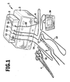
- the illustrated in the drawing RF surgical device 1 comprises a plurality of components, namely arranged in a separate housing RF generator 2, also arranged in a separate housing adapter 3 and two bipolar RF instruments 4 and 5, in the illustrated embodiment as a terminal or tweezers are formed.
- the HF surgical device has an HF output 6, via which RF energy is emitted, and a switching connection 7, via which signals can be supplied to the HF generator 2 for switching on and off.
- This switching connection 7 can be designed such that it normally, ie without operation of the adapter 3, is connected to a foot switch which is actuated by the surgeon.
- the switching connection 7 is connected via a switching cable 8 to a switching output 9 on the adapter 3.
- the HF output 6 is connected via an HF cable 10 to an HF input 11 on the adapter 3.
- the two HF instruments 4, 5 additionally each have a handset 16 or 17, these hand switches 16, 17 are also connected via the connection cable 14 and 15 to the terminals 12 and 13 respectively.
- FIG. 2 In the embodiment of FIG. 2 a similar arrangement is chosen, but only one terminal 12 is shown with an HF instrument 4 connected thereto.
- the adapter 3 can be supplied with electrical energy via a mains cable 18, and in addition, the adapter 3 in the embodiment of FIG. 1 nor a switching connection 19, to which a foot switch 20 can be connected.
- the adapter 3 is designed so that it connects the terminals 12, 13 with the RF input 11 and also with an electrical circuit 21 which processes the signals of the manual switches 16, 17 and connects them to the switching output 9.
- This electrical circuit 21 processes the signals coming from the manual switches 16 or 17 so that they can be effective at the switching terminal 7 of the RF generator 2, so that the manual switch work functionally the foot switches that are used in an operation of the RF generator 2 without adapter.
- the electrical circuit 21 can fulfill further functions, for example it can identify the connected HF instruments 4, 5. This identification can be carried out in a manner known per se, for example by detecting different resistances associated with the HF instruments or by reading out data from transponders on the HF instruments. In any case, the corresponding identification signals via the connecting cables 14, 15 are transmitted to the terminals 12, 13 and supplied from there to the electrical circuit 21.
- the electrical circuit 21 can also compare electrical nominal values corresponding to the respective HF instruments with the actual values of the electrical HF energy which are supplied by the HF generator 2, ie with the setting of the HF signal. generator. If there is a deviation exceeding a certain value, the adapter can generate a warning signal or switch off the power supply.
- the foot switch 20 can parallel to the manual switches 16, 17 or alternatively also the electrical circuit 21 are supplied with switching signals, which then lead to the activation of the RF generator 2.
- the manual switch 16, 17 so such a foot switch 20 is not essential, but it can be provided if the surgeon prefers to operate a foot switch in a conventional manner. It is also possible to trigger 20 additional switching operations with this foot switch to change the setting of the RF generator 2.
- the use of the adapter 3 makes it possible to use HF generators 2 of the conventional design with a single RF output and a separate switching connection and still work with instruments that have manual switches, possibly with multiple instruments that are used alternatively and be detected by the corresponding manual switch as switched-instruments, so that the RF energy is supplied only to these instruments, ie the adapter 3 can cause due to the operation of the handset 16, 17 that the RF energy is supplied only to the respective port of the adapter on which an operation of the manual switch has been determined.
Landscapes
- Health & Medical Sciences (AREA)
- Surgery (AREA)
- Engineering & Computer Science (AREA)
- Life Sciences & Earth Sciences (AREA)
- Biomedical Technology (AREA)
- Otolaryngology (AREA)
- Nuclear Medicine, Radiotherapy & Molecular Imaging (AREA)
- Plasma & Fusion (AREA)
- Physics & Mathematics (AREA)
- Heart & Thoracic Surgery (AREA)
- Medical Informatics (AREA)
- Molecular Biology (AREA)
- Animal Behavior & Ethology (AREA)
- General Health & Medical Sciences (AREA)
- Public Health (AREA)
- Veterinary Medicine (AREA)
- Surgical Instruments (AREA)
Description
- Die Erfindung betrifft ein HF-Chirurgiegerät mit einem HF-Generator, der einen HF-Ausgang und einen Schaltanschluss für ein externes Schaltelement aufweist, und mit mindestens einem bipolaren HF-Instrument, dem von dem HF-Ausgang des HF-Generators elektrische HF-Energie zugeführt wird und das einen Handschalter aufweist.
- Für bipolare HF-Instrumente sind HF-Generatoren bekannt, die einen HF-Ausgang aufweisen, an den die HF-Instrumente angeschlossen werden. Über den HF-Ausgang wird Hochfrequenzenergie von dem HF-Generator auf das HF-Instrument übertragen.
- Aktiviert, d.h. ein- und ausgeschaltet, werden diese HF-Generatoren üblicherweise durch einen Fußschalter, der als externes Schaltelement mit einem Schaltanschluss des HF-Generators verbunden ist.
- Mit derartigen HF-Generatoren kann also ein einziges HF-Instrument versorgt werden, das Ein- und Ausschalten erfolgt über den externen Fußschalter. Wenn ein weiteres HF-Instrument eingesetzt werden soll, muss das zuerst benutzte HF-Instrument von dem HF-Ausgang des HF-Generators gelöst werden und dann muss das weitere HF-Instrument angeschlossen werden, dies bedeutet im Operationssaal, das ein nicht steriler Helfer benötigt wird, um diesen Anschlusswechsel vorzunehmen.
- Es sind bipolare Instrumente bekannt, die an den Instrumenten Handschalter tragen, über die die Aktivierung und Deaktivierung des HF-Generators erfolgen kann. Zur Verarbeitung der Signale dieser Handschalter müssen jedoch die HF-Generatoren entsprechend ausgebildet sein, d.h. die HF-Ausgänge müssen zusätzliche Verbindungen für die Signale des Handschalters aufweisen, und dies ist bei vielen HF-Generatoren nicht der Fall, so dass die Handschalter nicht eingesetzt werden können, bei den meisten HF-Generatoren erfolgt die Aktivierung ausschließlich über externe Fußschalter.
- Ein Adapter zur Umschaltung zwischen mehreren Instrumenten ist aus
WO 01/37745 US 2001/0029315 bekannt, wobei eine direkte Weiterleitung ohne Umwandlung des Schaltsignals erfolgt. - Es ist Aufgabe der Erfindung, ein gattungsgemäßes HF-Chirurgiegerät so auszubilden, dass auch mit HF-Generatoren, die nur einen HF-Ausgang und einen Schaltanschluss für ein externes Schaltelement aufweisen, der Betrieb von HF-Instrumenten möglich wird, die Handschalter tragen, wobei die Handschalter funktionsgleich den Fußschaltern einsetzbar sein sollen, welche bei einem Betrieb des HF-Generators z ohne Adapter Verwendung finden.
- Diese Aufgabe wird erfindungsgemäß durch ein HF-Chirurgiegerät der eingangs beschriebenen Art gelöst, mit einem Adapter mit mindestens einem Anschluss für das HF-Instrument, einem HF-Eingang, der mit dem HF-Ausgang des HF-Generators verbunden ist, mit einem Schaltausgang, der mit dem Schaltanschluss am HF-Generator verbunden ist, und mit elektrischen Schaltelementen, die den Anschluss für das HF-Instrument einerseits mit dem HF-Eingang und andererseits mit dem Schaltausgang verbinden, wobei die Schaltelemente die Signale des Handschalters umwandeln in Schaltsignale für den Schaltanschluss des HF-Generators. So können beispielsweise Impedanzwandler eingesetzt werden oder andere elektrische Schaltelemente, die die Signale des Handschalters so verarbeiten, dass am Schaltausgang des Adapters Signale erzeugt werden, die für den Schaltanschluss des HF-Generators wirksam sind.
- Gemäß einer weiteren vorteilhaften Ausgestaltung der Erfindung kann vorgesehen sein, dass die HF-Instrumente Identifikationselemente tragen, die über den Anschluss für ein HF-Instrument an eine Erkennungsschaltung im Adapter angeschlossen sind. Derartige Identifikationselemente können beispielsweise Widerstände unterschiedlicher Größe sein oder aber Transponder mit entsprechenden Daten, die von dem Adapter ausgelesen werden können. Die Datenübertragung erfolgt dabei in jedem Falle über den Anschluss für das HF-Instrument am Adapter.
- Vorteilhaft ist es, wenn die Erkennungsschaltung elektrische Sollwerte für das angeschlossene HF-Instrument und elektrische Ist-Werte, die der jeweiligen Einstellung des HF-Generators entsprechen, vergleicht und bei einer Abweichung, die einen vorgegebenen Wert übersteigt, ein Warn- und/oder Abschaltsignal erzeugt.
- Der Adapter kann einen Schaltanschluss für ein externes Schaltelement aufweisen, der mit dem Schaltausgang des Adapters in Verbindung steht. An diesem Schaltanschluss kann beispielsweise ein Fußschalter angeschlossen werden, über den ebenfalls die Aktivierung des HF-Generators erfolgt. Dieser Fußschalter kann alternativ oder zusätzlich zu den Handschaltern Verwendung finden, das Signal des externen Schaltelementes wird im Adapter so bearbeitet, dass es am Schaltausgang des Adapters in einer Form vorliegt, die für den Schaltanschluss des HF-Generators verträglich ist.
- Vorzugsweise ist der Adapter in einem eigenen Gehäuse angeordnet.
- Der Adapter kann mittels Anschlusskabelkabel mit dem HF-Ausgang und dem Schaltanschluss des HF-Generators verbunden sein.
- Die Erfindung bezieht sich nicht nur auf ein HF-Chirurgiegerät, welches den HF-Generator, den Adapter und angeschlossene HF-Instrumente betrifft, sondern auch auf den entsprechend ausgebildeten Adapter an sich.
- Die nachfolgende Beschreibung bevorzugter Ausführungsformen der Erfindung dient im Zusammenhang mit der Zeichnung der näheren Erläuterung. Es zeigen:
- Figur 1:
- ein HF-Chirurgiegerät mit einem HF-Generator, einem Adapter und zwei daran angeschlossenen HF-Instrumenten und
- Figur 2:
- eine schematische Draufsicht auf ein HF- Chirurgiegerät gemäß
Figur 1 mit nur einem angeschlossenen HF-Instrument. - Das in der Zeichnung dargestellte HF-Chirurgiegerät 1 umfasst mehrere Komponenten, nämlich einen in einem eigenen Gehäuse angeordneten HF-Generator 2, einen ebenfalls in einem eigenen Gehäuse angeordneten Adapter 3 sowie zwei bipolare HF-Instrumente 4 und 5, die im dargestellten Ausführungsbeispiel als Klemme bzw. Pinzette ausgebildet sind.
- Das HF-Chirurgiegerät weist einen HF-Ausgang 6 auf, über den HF-Energie abgegeben wird, und einen Schaltanschluss 7, über den dem HF-Generator 2 Signale zum Ein- und Ausschalten zugeführt werden können. Dieser Schaltanschluss 7 kann so ausgebildet sein, dass er normalerweise, d.h. ohne Betrieb des Adapters 3, mit einem Fußschalter in Verbindung steht, der vom Operateur betätigt wird.
- Bei Verwendung des Adapters 3 jedoch ist der Schaltanschluss 7 über ein Schaltkabel 8 verbunden mit einem Schaltausgang 9 am Adapter 3. Der HF-Ausgang 6 ist über ein HF-Kabel 10 verbunden mit einem HF-Eingang 11 am Adapter 3.
- Dieser trägt bei dem Ausführungsbeispiel der
Figur 1 zwei Anschlüsse 12, 13, an jeden dieser Anschlüsse 12, 13 ist über ein Anschlusskabel 14 bzw. 15 jeweils eines der beiden HF-Instrumente 4, 5 angeschlossen. - Die beiden HF-Instrumente 4, 5 weisen zusätzlich jeweils einen Handschalter 16 bzw. 17 auf, diese Handschalter 16, 17 sind ebenfalls über die Anschlusskabel 14 und 15 mit den Anschlüssen 12 bzw. 13 verbunden.
- Beim Ausführungsbeispiel der
Figur 2 ist eine ähnliche Anordnung gewählt, jedoch ist nur ein Anschluss 12 mit einem daran angeschlossenen HF-Instrument 4 dargestellt. - Der Adapter 3 kann über ein Netzkabel 18 mit elektrischer Energie versorgt werden, und außerdem weist der Adapter 3 beim Ausführungsbeispiel der
Figur 1 noch einen Schaltanschluss 19 auf, an den ein Fußschalter 20 angeschlossen werden kann. - Der Adapter 3 ist so ausgebildet, dass er die Anschlüsse 12, 13 mit dem HF-Eingang 11 verbindet und außerdem mit einer elektrischen Schaltung 21, die die Signale der Handschalter 16, 17 verarbeitet und diese mit dem Schaltausgang 9 verbindet. Diese elektrische Schaltung 21 verarbeitet die Signale, die von den Handschaltern 16 oder 17 stammen, so, dass sie am Schaltanschluss 7 des HF-Generators 2 wirksam werden können, so dass die Handschalter funktionsgleich den Fußschaltern arbeiten, die bei einem Betrieb des HF-Generators 2 ohne Adapter Verwendung finden.
- Die elektrische Schaltung 21 kann weitere Funktionen erfüllen, beispielsweise kann sie die angeschlossenen HF-Instrumente 4, 5 identifizieren. Diese Identifikation kann in an sich bekannter Weise erfolgen, beispielsweise durch die Erkennung unterschiedlicher Widerstände, die den HF-Instrumenten zugeordnet sind, oder durch Auslesen von Daten aus Transpondern auf den HF-Instrumenten. In jedem Falle werden die entsprechenden Identifikationssignale über die Anschlusskabel 14, 15 auf die Anschlüsse 12, 13 übertragen und von dort der elektrischen Schaltung 21 zugeführt.
- Mit der Identifikation der angeschlossenen Instrumente kann die elektrische Schaltung 21 außerdem den jeweiligen HF-Instrumenten entsprechende elektrische Soll-Werte mit den Ist-Werten der elektrischen HF-Energie vergleichen, die vom HF-Generator 2 zugeführt werden, also mit der Einstellung des HF-Generators. Wenn eine einen bestimmten Wert übersteigende Abweichung vorliegt, kann der Adapter ein Warnsignal erzeugen oder die Stromzufuhr abschalten.
- Über den Fußschalter 20 kann parallel zu den Handschaltern 16, 17 oder alternativ ebenfalls die elektrische Schaltung 21 mit Schaltsignalen versorgt werden, die dann zur Aktivierung des HF-Generators 2 führen. Bei Verwendung der Handschalter 16, 17 ist also ein solcher Fußschalter 20 nicht unbedingt notwendig, er kann aber vorgesehen werden, falls der Operateur es vorzieht, in herkömmlicher Weise einen Fußschalter zu betätigen. Es ist auch möglich, mit diesem Fußschalter 20 zusätzliche Schaltvorgänge auszulösen, um die Einstellung des HF-Generators 2 zu verändern.
- Die Verwendung des Adapters 3 ermöglicht es, HF-Generatoren 2 der konventionellen Bauweise mit einem einzigen HF-Ausgang und einem davon getrennten Schaltanschluss zu verwenden und trotzdem mit Instrumenten zu arbeiten, die Handschalter aufweisen, gegebenenfalls auch mit mehreren Instrumenten, die alternativ eingesetzt werden und durch Betätigung der entsprechenden Handschalter auch als eingeschaltete Instrumente erkannt werden, so dass die HF-Energie nur diesen Instrumenten zugeführt wird, d.h. der Adapter 3 kann aufgrund der Betätigung der Handschalter 16, 17 veranlassen, dass die HF-Energie nur dem jeweiligen Anschluss des Adapters zugeführt wird, an dem eine Betätigung des Handschalters festgestellt worden ist.
- Auf diese Weise können konventionelle HF-Generatoren sehr viel vielseitiger eingesetzt werden, ohne dass bauliche Veränderungen notwendig sind, insbesondere können Wechsel beim Anschluss der Instrumente vermieden werden, d.h. alle Instrumente können während einer Operation dauerhaft über den Adapter 3 mit dem HF-Generator verbunden bleiben.
Claims (8)
- HF-Chirurgiegerät (1), umfassend
einen HF-Generator (2), der einen HF-Ausgang (6) und einen Schaltanschluss (7) für ein externes Schaltelement aufweist
über den dem HF-Generator (2) Signale zum Ein- und Ausschalten zugeführt werden können,
und mindestens ein bipolares HF-Instrument (4, 5), dem von dem HF-Ausgang (6) des HF-Generators (2) elektrische HF-Energie zugeführt wird und das einen Handschalter (16, 17) aufweist,
sowie einen Adapter (3) mit mindestens einem Anschluss (12, 13) für das HF-Instrument (4, 5), einem HF-Eingang (11), der mit dem HF-Ausgang des HF-Generators (2) verbunden ist, mit einem Schaltausgang (9) und mit elektrischen Schaltelementen (21), die den Anschluss (12, 13) für das HF-Instrument mit dem HF-Eingang (11) verbinden, dadurch gekennzeichnet, dass der Adapter (3) einen mit dem Schaltanschluss (7) am HF-Generator (2) verbundenen Schaltausgang (9) aufweist sowie elektrische Schaltelemente (21), die den Anschluss (12, 13) für das HF-Instrument (4, 5) mit dem Schaltausgang (9) verbinden und die Signale des Handschalters (16, 17) umwandeln in Schaltsignale für den Schaltanschluss (7) des HF-Generators (2), so dass die Handschalter (16, 17) funktionsgleich den externen Schaltelementen arbeiten, die bei einem Betrieb des HF-Generators (2) ohne Adapter Verwendung finden. - HF-Chirurgiegerät nach Anspruch 1, dadurch gekennzeichnet, dass mehrere Anschlüsse (12, 13) für HF-Instrumente (4, 5) am Adapter (3) vorgesehen sind, die einerseits mit dem HF-Eingang (11) und andererseits mit dem Schaltausgang (9) verbunden sind.
- HF-Chirurgiegerät nach einem der voranstehenden Ansprüche, dadurch gekennzeichnet, dass die HF-Instrumente (4, 5) Identifikationselemente tragen, die über den Anschluss (12, 13) für ein HF-Instrument an eine Erkennungsschaltung (21) im Adapter (3) angeschlossen sind.
- HF-Chirurgiegerät nach Anspruch 3, dadurch gekennzeichnet, dass die Erkennungsschaltung (21) elektrische Sollwerte für das angeschlossene HF-Instrument (4, 5) und elektrische Ist-Werte, die der jeweiligen Einstellung des HF-Generators (2) entsprechen, vergleicht und bei einer Abweichung, die einen vorgegebenen Wert übersteigt, ein Warn- und/oder Abschaltsignal erzeugt.
- HF-Chirurgiegerät nach einem der voranstehenden Ansprüche, dadurch gekennzeichnet, dass der Adapter (3) einen Schaltanschluss (19) für ein externes Schaltelement (20) aufweist, der mit dem Schaltausgang (9) des Adapters (3) in Verbindung steht.
- HF-Chirurgiegerät nach einem der voranstehenden Ansprüche, dadurch gekennzeichnet, dass der Adapter (3) in einem eigenen Gehäuse angeordnet ist.
- HF-Chirurgiegerät nach Anspruch 6, dadurch gekennzeichnet, dass der Adapter (3) über Anschlusskabel (8, 10) mit dem HF-Ausgang (6) und dem Schaltanschluss (7) des HF-Generators (2) verbunden ist.
- Adapter (3) mit den Merkmalen eines der voranstehenden Ansprüche.
Applications Claiming Priority (1)
| Application Number | Priority Date | Filing Date | Title |
|---|---|---|---|
| DE102006040502A DE102006040502A1 (de) | 2006-08-30 | 2006-08-30 | HF-Chirurgiegerät und Adapter für dieses Gerät |
Publications (2)
| Publication Number | Publication Date |
|---|---|
| EP1894537A1 EP1894537A1 (de) | 2008-03-05 |
| EP1894537B1 true EP1894537B1 (de) | 2010-07-28 |
Family
ID=38885292
Family Applications (1)
| Application Number | Title | Priority Date | Filing Date |
|---|---|---|---|
| EP07115220A Not-in-force EP1894537B1 (de) | 2006-08-30 | 2007-08-29 | HF-Chirurgiegerät und Adapter für dieses Gerät |
Country Status (4)
| Country | Link |
|---|---|
| EP (1) | EP1894537B1 (de) |
| AT (1) | ATE475371T1 (de) |
| DE (2) | DE102006040502A1 (de) |
| ES (1) | ES2347599T3 (de) |
Family Cites Families (8)
| Publication number | Priority date | Publication date | Assignee | Title |
|---|---|---|---|---|
| US3952748A (en) * | 1974-07-18 | 1976-04-27 | Minnesota Mining And Manufacturing Company | Electrosurgical system providing a fulguration current |
| US4071028A (en) * | 1976-02-17 | 1978-01-31 | Perkins George C | Radio frequency cautery instrument and control unit therefor |
| US5391144A (en) * | 1990-02-02 | 1995-02-21 | Olympus Optical Co., Ltd. | Ultrasonic treatment apparatus |
| DE4339049C2 (de) * | 1993-11-16 | 2001-06-28 | Erbe Elektromedizin | Einrichtung zur Konfiguration chirurgischer Systeme |
| DE19957919A1 (de) * | 1999-11-25 | 2001-06-21 | Ethicon Gmbh | Schaltvorrichtung für elektrochirurgische Geräte |
| US6623423B2 (en) * | 2000-02-29 | 2003-09-23 | Olympus Optical Co., Ltd. | Surgical operation system |
| DE10253819A1 (de) * | 2002-11-18 | 2004-07-01 | Storz Endoskop Produktions Gmbh | Elektrochirurgische Vorrichtung sowie Verfahren zum Betreiben derselben |
| US7217269B2 (en) * | 2003-10-28 | 2007-05-15 | Uab Research Foundation | Electrosurgical control system |
-
2006
- 2006-08-30 DE DE102006040502A patent/DE102006040502A1/de not_active Withdrawn
-
2007
- 2007-08-29 EP EP07115220A patent/EP1894537B1/de not_active Not-in-force
- 2007-08-29 AT AT07115220T patent/ATE475371T1/de active
- 2007-08-29 DE DE502007004538T patent/DE502007004538D1/de active Active
- 2007-08-29 ES ES07115220T patent/ES2347599T3/es active Active
Also Published As
| Publication number | Publication date |
|---|---|
| EP1894537A1 (de) | 2008-03-05 |
| DE102006040502A1 (de) | 2008-03-13 |
| DE502007004538D1 (de) | 2010-09-09 |
| ES2347599T3 (es) | 2010-11-02 |
| ATE475371T1 (de) | 2010-08-15 |
Similar Documents
| Publication | Publication Date | Title |
|---|---|---|
| DE4339049C2 (de) | Einrichtung zur Konfiguration chirurgischer Systeme | |
| EP1337194B1 (de) | Verfahren zum betreiben eines instruments für die hf-chirurgie und elektrochirurgische vorrichtung | |
| EP2224871B1 (de) | Chirurgiegerätesteckersystem | |
| EP0285962B1 (de) | Überwachungsschaltung für ein HF-Chirurgiegerät | |
| EP2004080B1 (de) | Verbindungskabel | |
| EP1649820A1 (de) | Elektrochirurgische Vorrichtung | |
| DE10262088B4 (de) | Chirurgisches Motorensystem | |
| EP1685577A1 (de) | Steuereinrichtung zur steuerung elektromedizinischer geräte | |
| WO2003090790A2 (de) | Vorrichtung zur überwachung medizinischer geräte | |
| EP2497427A1 (de) | Chirurgisches Instrument mit digitaler Datenschnittstelle | |
| DE3427517C2 (de) | ||
| EP2498270B1 (de) | Sicherheitsrelais und sicherheitsgerichtetes Kommunikationssystem | |
| DE102018129796A1 (de) | Sichere Spannungsüberwachung | |
| EP3179893B1 (de) | Elektrisches küchengerät | |
| EP1796566B1 (de) | Apc-gerät | |
| DE10109864A1 (de) | Sicherheitsschaltvorrichtung | |
| EP3334359B1 (de) | Verfahren und vorrichtung zur steuerung der energiezufuhr zu einem medizinischen instrument | |
| EP3496638A1 (de) | Elektrochirurgiesystem mit messeinheit | |
| EP1894537A1 (de) | HF-Chirurgiegerät und Adapter für dieses Gerät | |
| DE202006013309U1 (de) | HF-Chirurgiegerät und Adapter für dieses Gerät | |
| EP2245981A2 (de) | Fernbedienung für ein Operations-Assistenz-System | |
| DE102005040487B4 (de) | HF-Chirurgiegerät | |
| DE3739009C2 (de) | Zahnärztliche Einrichtung mit Mitteln zur Zufuhr von HF- und NF-Energie an ein zahnärztliches Handstück | |
| EP2196670B1 (de) | Mit einer vakuumkomponente verbindbares gerät | |
| DE19957919A1 (de) | Schaltvorrichtung für elektrochirurgische Geräte |
Legal Events
| Date | Code | Title | Description |
|---|---|---|---|
| PUAI | Public reference made under article 153(3) epc to a published international application that has entered the european phase |
Free format text: ORIGINAL CODE: 0009012 |
|
| AK | Designated contracting states |
Kind code of ref document: A1 Designated state(s): AT BE BG CH CY CZ DE DK EE ES FI FR GB GR HU IE IS IT LI LT LU LV MC MT NL PL PT RO SE SI SK TR |
|
| AX | Request for extension of the european patent |
Extension state: AL BA HR MK YU |
|
| RAP1 | Party data changed (applicant data changed or rights of an application transferred) |
Owner name: AESCULAP AG |
|
| 17P | Request for examination filed |
Effective date: 20080827 |
|
| 17Q | First examination report despatched |
Effective date: 20081006 |
|
| AKX | Designation fees paid |
Designated state(s): AT BE BG CH CY CZ DE DK EE ES FI FR GB GR HU IE IS IT LI LT LU LV MC MT NL PL PT RO SE SI SK TR |
|
| GRAJ | Information related to disapproval of communication of intention to grant by the applicant or resumption of examination proceedings by the epo deleted |
Free format text: ORIGINAL CODE: EPIDOSDIGR1 |
|
| GRAP | Despatch of communication of intention to grant a patent |
Free format text: ORIGINAL CODE: EPIDOSNIGR1 |
|
| GRAP | Despatch of communication of intention to grant a patent |
Free format text: ORIGINAL CODE: EPIDOSNIGR1 |
|
| GRAS | Grant fee paid |
Free format text: ORIGINAL CODE: EPIDOSNIGR3 |
|
| GRAA | (expected) grant |
Free format text: ORIGINAL CODE: 0009210 |
|
| AK | Designated contracting states |
Kind code of ref document: B1 Designated state(s): AT BE BG CH CY CZ DE DK EE ES FI FR GB GR HU IE IS IT LI LT LU LV MC MT NL PL PT RO SE SI SK TR |
|
| REG | Reference to a national code |
Ref country code: GB Ref legal event code: FG4D Free format text: NOT ENGLISH |
|
| REG | Reference to a national code |
Ref country code: CH Ref legal event code: EP |
|
| REG | Reference to a national code |
Ref country code: IE Ref legal event code: FG4D Free format text: LANGUAGE OF EP DOCUMENT: GERMAN |
|
| REF | Corresponds to: |
Ref document number: 502007004538 Country of ref document: DE Date of ref document: 20100909 Kind code of ref document: P |
|
| REG | Reference to a national code |
Ref country code: ES Ref legal event code: FG2A Ref document number: 2347599 Country of ref document: ES Kind code of ref document: T3 |
|
| REG | Reference to a national code |
Ref country code: NL Ref legal event code: VDEP Effective date: 20100728 |
|
| LTIE | Lt: invalidation of european patent or patent extension |
Effective date: 20100728 |
|
| PG25 | Lapsed in a contracting state [announced via postgrant information from national office to epo] |
Ref country code: LT Free format text: LAPSE BECAUSE OF FAILURE TO SUBMIT A TRANSLATION OF THE DESCRIPTION OR TO PAY THE FEE WITHIN THE PRESCRIBED TIME-LIMIT Effective date: 20100728 Ref country code: FI Free format text: LAPSE BECAUSE OF FAILURE TO SUBMIT A TRANSLATION OF THE DESCRIPTION OR TO PAY THE FEE WITHIN THE PRESCRIBED TIME-LIMIT Effective date: 20100728 Ref country code: NL Free format text: LAPSE BECAUSE OF FAILURE TO SUBMIT A TRANSLATION OF THE DESCRIPTION OR TO PAY THE FEE WITHIN THE PRESCRIBED TIME-LIMIT Effective date: 20100728 |
|
| BERE | Be: lapsed |
Owner name: AESCULAP A.G. Effective date: 20100831 |
|
| PG25 | Lapsed in a contracting state [announced via postgrant information from national office to epo] |
Ref country code: BG Free format text: LAPSE BECAUSE OF FAILURE TO SUBMIT A TRANSLATION OF THE DESCRIPTION OR TO PAY THE FEE WITHIN THE PRESCRIBED TIME-LIMIT Effective date: 20101028 Ref country code: IS Free format text: LAPSE BECAUSE OF FAILURE TO SUBMIT A TRANSLATION OF THE DESCRIPTION OR TO PAY THE FEE WITHIN THE PRESCRIBED TIME-LIMIT Effective date: 20101128 Ref country code: PL Free format text: LAPSE BECAUSE OF FAILURE TO SUBMIT A TRANSLATION OF THE DESCRIPTION OR TO PAY THE FEE WITHIN THE PRESCRIBED TIME-LIMIT Effective date: 20100728 Ref country code: CY Free format text: LAPSE BECAUSE OF FAILURE TO SUBMIT A TRANSLATION OF THE DESCRIPTION OR TO PAY THE FEE WITHIN THE PRESCRIBED TIME-LIMIT Effective date: 20100728 Ref country code: PT Free format text: LAPSE BECAUSE OF FAILURE TO SUBMIT A TRANSLATION OF THE DESCRIPTION OR TO PAY THE FEE WITHIN THE PRESCRIBED TIME-LIMIT Effective date: 20101129 Ref country code: SI Free format text: LAPSE BECAUSE OF FAILURE TO SUBMIT A TRANSLATION OF THE DESCRIPTION OR TO PAY THE FEE WITHIN THE PRESCRIBED TIME-LIMIT Effective date: 20100728 |
|
| REG | Reference to a national code |
Ref country code: IE Ref legal event code: FD4D |
|
| PG25 | Lapsed in a contracting state [announced via postgrant information from national office to epo] |
Ref country code: LV Free format text: LAPSE BECAUSE OF FAILURE TO SUBMIT A TRANSLATION OF THE DESCRIPTION OR TO PAY THE FEE WITHIN THE PRESCRIBED TIME-LIMIT Effective date: 20100728 Ref country code: SE Free format text: LAPSE BECAUSE OF FAILURE TO SUBMIT A TRANSLATION OF THE DESCRIPTION OR TO PAY THE FEE WITHIN THE PRESCRIBED TIME-LIMIT Effective date: 20100728 Ref country code: GR Free format text: LAPSE BECAUSE OF FAILURE TO SUBMIT A TRANSLATION OF THE DESCRIPTION OR TO PAY THE FEE WITHIN THE PRESCRIBED TIME-LIMIT Effective date: 20101029 Ref country code: MC Free format text: LAPSE BECAUSE OF NON-PAYMENT OF DUE FEES Effective date: 20100831 |
|
| PG25 | Lapsed in a contracting state [announced via postgrant information from national office to epo] |
Ref country code: DK Free format text: LAPSE BECAUSE OF FAILURE TO SUBMIT A TRANSLATION OF THE DESCRIPTION OR TO PAY THE FEE WITHIN THE PRESCRIBED TIME-LIMIT Effective date: 20100728 Ref country code: IE Free format text: LAPSE BECAUSE OF FAILURE TO SUBMIT A TRANSLATION OF THE DESCRIPTION OR TO PAY THE FEE WITHIN THE PRESCRIBED TIME-LIMIT Effective date: 20100728 |
|
| PG25 | Lapsed in a contracting state [announced via postgrant information from national office to epo] |
Ref country code: RO Free format text: LAPSE BECAUSE OF FAILURE TO SUBMIT A TRANSLATION OF THE DESCRIPTION OR TO PAY THE FEE WITHIN THE PRESCRIBED TIME-LIMIT Effective date: 20100728 Ref country code: CZ Free format text: LAPSE BECAUSE OF FAILURE TO SUBMIT A TRANSLATION OF THE DESCRIPTION OR TO PAY THE FEE WITHIN THE PRESCRIBED TIME-LIMIT Effective date: 20100728 Ref country code: EE Free format text: LAPSE BECAUSE OF FAILURE TO SUBMIT A TRANSLATION OF THE DESCRIPTION OR TO PAY THE FEE WITHIN THE PRESCRIBED TIME-LIMIT Effective date: 20100728 Ref country code: SK Free format text: LAPSE BECAUSE OF FAILURE TO SUBMIT A TRANSLATION OF THE DESCRIPTION OR TO PAY THE FEE WITHIN THE PRESCRIBED TIME-LIMIT Effective date: 20100728 |
|
| PLBE | No opposition filed within time limit |
Free format text: ORIGINAL CODE: 0009261 |
|
| STAA | Information on the status of an ep patent application or granted ep patent |
Free format text: STATUS: NO OPPOSITION FILED WITHIN TIME LIMIT |
|
| 26N | No opposition filed |
Effective date: 20110429 |
|
| PG25 | Lapsed in a contracting state [announced via postgrant information from national office to epo] |
Ref country code: BE Free format text: LAPSE BECAUSE OF NON-PAYMENT OF DUE FEES Effective date: 20100831 |
|
| REG | Reference to a national code |
Ref country code: DE Ref legal event code: R097 Ref document number: 502007004538 Country of ref document: DE Effective date: 20110429 |
|
| PG25 | Lapsed in a contracting state [announced via postgrant information from national office to epo] |
Ref country code: MT Free format text: LAPSE BECAUSE OF FAILURE TO SUBMIT A TRANSLATION OF THE DESCRIPTION OR TO PAY THE FEE WITHIN THE PRESCRIBED TIME-LIMIT Effective date: 20100728 |
|
| REG | Reference to a national code |
Ref country code: CH Ref legal event code: PL |
|
| PG25 | Lapsed in a contracting state [announced via postgrant information from national office to epo] |
Ref country code: CH Free format text: LAPSE BECAUSE OF NON-PAYMENT OF DUE FEES Effective date: 20110831 Ref country code: LI Free format text: LAPSE BECAUSE OF NON-PAYMENT OF DUE FEES Effective date: 20110831 |
|
| PG25 | Lapsed in a contracting state [announced via postgrant information from national office to epo] |
Ref country code: HU Free format text: LAPSE BECAUSE OF FAILURE TO SUBMIT A TRANSLATION OF THE DESCRIPTION OR TO PAY THE FEE WITHIN THE PRESCRIBED TIME-LIMIT Effective date: 20110129 Ref country code: LU Free format text: LAPSE BECAUSE OF NON-PAYMENT OF DUE FEES Effective date: 20100829 |
|
| PG25 | Lapsed in a contracting state [announced via postgrant information from national office to epo] |
Ref country code: TR Free format text: LAPSE BECAUSE OF FAILURE TO SUBMIT A TRANSLATION OF THE DESCRIPTION OR TO PAY THE FEE WITHIN THE PRESCRIBED TIME-LIMIT Effective date: 20100728 |
|
| REG | Reference to a national code |
Ref country code: AT Ref legal event code: MM01 Ref document number: 475371 Country of ref document: AT Kind code of ref document: T Effective date: 20120831 |
|
| PG25 | Lapsed in a contracting state [announced via postgrant information from national office to epo] |
Ref country code: AT Free format text: LAPSE BECAUSE OF NON-PAYMENT OF DUE FEES Effective date: 20120831 |
|
| REG | Reference to a national code |
Ref country code: DE Ref legal event code: R082 Ref document number: 502007004538 Country of ref document: DE Representative=s name: HOEGER, STELLRECHT & PARTNER PATENTANWAELTE MB, DE |
|
| REG | Reference to a national code |
Ref country code: FR Ref legal event code: PLFP Year of fee payment: 10 |
|
| PGFP | Annual fee paid to national office [announced via postgrant information from national office to epo] |
Ref country code: GB Payment date: 20160824 Year of fee payment: 10 Ref country code: IT Payment date: 20160823 Year of fee payment: 10 |
|
| PGFP | Annual fee paid to national office [announced via postgrant information from national office to epo] |
Ref country code: FR Payment date: 20160825 Year of fee payment: 10 |
|
| PGFP | Annual fee paid to national office [announced via postgrant information from national office to epo] |
Ref country code: ES Payment date: 20160829 Year of fee payment: 10 |
|
| GBPC | Gb: european patent ceased through non-payment of renewal fee |
Effective date: 20170829 |
|
| REG | Reference to a national code |
Ref country code: FR Ref legal event code: ST Effective date: 20180430 |
|
| PG25 | Lapsed in a contracting state [announced via postgrant information from national office to epo] |
Ref country code: GB Free format text: LAPSE BECAUSE OF NON-PAYMENT OF DUE FEES Effective date: 20170829 |
|
| PG25 | Lapsed in a contracting state [announced via postgrant information from national office to epo] |
Ref country code: FR Free format text: LAPSE BECAUSE OF NON-PAYMENT OF DUE FEES Effective date: 20170831 Ref country code: IT Free format text: LAPSE BECAUSE OF NON-PAYMENT OF DUE FEES Effective date: 20170829 |
|
| REG | Reference to a national code |
Ref country code: ES Ref legal event code: FD2A Effective date: 20181025 |
|
| PG25 | Lapsed in a contracting state [announced via postgrant information from national office to epo] |
Ref country code: ES Free format text: LAPSE BECAUSE OF NON-PAYMENT OF DUE FEES Effective date: 20170830 |
|
| REG | Reference to a national code |
Ref country code: DE Ref legal event code: R082 Ref document number: 502007004538 Country of ref document: DE Representative=s name: HOEGER, STELLRECHT & PARTNER PATENTANWAELTE MB, DE |
|
| PGFP | Annual fee paid to national office [announced via postgrant information from national office to epo] |
Ref country code: DE Payment date: 20220822 Year of fee payment: 16 |
|
| REG | Reference to a national code |
Ref country code: DE Ref legal event code: R119 Ref document number: 502007004538 Country of ref document: DE |
|
| PG25 | Lapsed in a contracting state [announced via postgrant information from national office to epo] |
Ref country code: DE Free format text: LAPSE BECAUSE OF NON-PAYMENT OF DUE FEES Effective date: 20240301 |