EP1894489A2 - Method for manufacturing brushes - Google Patents
Method for manufacturing brushes Download PDFInfo
- Publication number
- EP1894489A2 EP1894489A2 EP07075670A EP07075670A EP1894489A2 EP 1894489 A2 EP1894489 A2 EP 1894489A2 EP 07075670 A EP07075670 A EP 07075670A EP 07075670 A EP07075670 A EP 07075670A EP 1894489 A2 EP1894489 A2 EP 1894489A2
- Authority
- EP
- European Patent Office
- Prior art keywords
- fiber
- fiber holder
- fibers
- fiber bundle
- support
- Prior art date
- Legal status (The legal status is an assumption and is not a legal conclusion. Google has not performed a legal analysis and makes no representation as to the accuracy of the status listed.)
- Withdrawn
Links
Images

Classifications
-
- A—HUMAN NECESSITIES
- A45—HAND OR TRAVELLING ARTICLES
- A45D—HAIRDRESSING OR SHAVING EQUIPMENT; EQUIPMENT FOR COSMETICS OR COSMETIC TREATMENTS, e.g. FOR MANICURING OR PEDICURING
- A45D34/00—Containers or accessories specially adapted for handling liquid toiletry or cosmetic substances, e.g. perfumes
- A45D34/04—Appliances specially adapted for applying liquid, e.g. using roller or ball
- A45D34/042—Appliances specially adapted for applying liquid, e.g. using roller or ball using a brush or the like
- A45D34/045—Appliances specially adapted for applying liquid, e.g. using roller or ball using a brush or the like connected to the cap of the container
-
- A—HUMAN NECESSITIES
- A46—BRUSHWARE
- A46B—BRUSHES
- A46B3/00—Brushes characterised by the way in which the bristles are fixed or joined in or on the brush body or carrier
- A46B3/06—Brushes characterised by the way in which the bristles are fixed or joined in or on the brush body or carrier by welding together bristles made of metal wires or plastic materials
-
- A—HUMAN NECESSITIES
- A46—BRUSHWARE
- A46D—MANUFACTURE OF BRUSHES
- A46D1/00—Bristles; Selection of materials for bristles
- A46D1/02—Bristles details
- A46D1/0284—Bristles having rounded ends
-
- A—HUMAN NECESSITIES
- A46—BRUSHWARE
- A46D—MANUFACTURE OF BRUSHES
- A46D9/00—Machines for finishing brushes
- A46D9/02—Cutting; Trimming
-
- A—HUMAN NECESSITIES
- A46—BRUSHWARE
- A46B—BRUSHES
- A46B2200/00—Brushes characterized by their functions, uses or applications
- A46B2200/10—For human or animal care
- A46B2200/1046—Brush used for applying cosmetics
-
- A—HUMAN NECESSITIES
- A46—BRUSHWARE
- A46B—BRUSHES
- A46B5/00—Brush bodies; Handles integral with brushware
Definitions
- the present invention concerns a method for manufacturing brushes, in particular of the type of a paint brush with a stick and hairs.
- Such brushes are applied for example in bottles of nail polish or corrector whereby the brush is for example fixed to the stopper of the bottle.
- such brushes are manufactured at present by taking a round bundle of fibers from a cartridge containing fibers that have been cut at length beforehand and by subsequently bending these fibers double and by fixing them with the double-bent ends in a blind hole in the stick by means of a clamp or a metal plate.
- a disadvantage of this known method lies in the use of clamps, which are disadvantageous to the production cost of such brushes and are detrimental to the environment when such brushes end up in the waste heap.
- Another disadvantage is that, each time the production has to switch to another shape of this type of brush, the production line or production machine must be reset to a considerable extent.
- Another additional disadvantage is that, in order to obtain a profiled far end for the fiber bundle, a profile knife is required whose purchase price is relatively high and which has to be replaced or sharpened regularly, to which end the required safety measures must be taken into account.
- the present invention aims to remedy one or several of the above-mentioned and other disadvantages.
- the invention concerns a method for manufacturing a brush of the above-mentioned type whereby the stick is made of at least two loose parts, namely a first part in the form of an actual stick and a second part in the form of a fiber holder to be provided on the latter with a passage in which the fibers can be held and whereby the method consists in picking up at least one fiber bundle from a supply of fibers, in providing the at least one picked-up fiber bundle in the axial direction through the above-mentioned passage of the fiber holder in such a manner that at least one fiber bundle protrudes with both far ends of the fibers over a length out of the passage, in melting or gluing together the far ends of the fibers on one far end of the bundle so as to prevent the fiber bundle from being withdrawn from the fiber holder, and in providing and fixing the fiber holder together with the fibers on the actual stick, either or not in another place and/or at another time.
- An advantage of this method is that it is no longer required to use a clamp, which implies a saving in material and which is more ecologically sound.
- the production department can respond in a more flexible manner to the needs of the market, since when a model is changed, the production line requires far less resets as the fiber holder can be easily combined with different sticks.
- the fiber holder can be advantageously made as a cap that is pushed over a far end of the actual stick, or in the shape of a stopper that is pushed in an axial recess of the actual stick and that is fixed by means of jointing techniques that are easy to apply such as snapping in, gluing, welding and the like.
- the fiber bundles that have been picked up they can be first provided in a support having at least one through hole; this support can be provided with the above-mentioned fiber bundle opposite the fiber holder of the brush with its through hole in the prolongation of the passage in the fiber holder, and the fiber bundle can be axially pushed from the support into the passage of the fiber holder by means of a punch that can be shifted in the through hole of the support.
- the fiber bundle can be provided in a relatively simple manner from the fiber pick-up device into the fiber holder of the brush.
- This support also makes it possible to more easily mechanize and automate the method.
- use can further be made of a punch with a pre-formed head to give the free end of the fiber bundle a required relief shape that may deviate from a fiber bundle with a straight cut.
- an intermediate plate can be applied that is provided between the support and the fiber holder and that is provided with at least one conducting channel which connects the through hole of the support to the passage in the fiber holder.
- This intermediate plate makes it possible, for example, to apply fiber bundles in the brush whose shape differs from a round bundle with a circular section as has been the case up to now.
- an intermediate plate is selected with a conducting channel whose crosscut shape is adjusted to the required shape of the ultimate fiber bundle of the brush.
- the brush 1 represented in figures 1 and 2 is a brush of the type as is used for example in a bottle of nail polish whereby the brush is fixed to the stopper 2 of the bottle concerned.
- the brush 1 is of the paint brush type with a stick 3 and fibers or hairs 4, whereby the stick 3 is in this case made of two parts, namely a first part in the shape of an actual stick 5 and a second part in the shape of a fiber holder 6 that is fixed to the actual stick 5 and that is provided with a passage 7 in which the fibers 4 are held in a bundle 8.
- the fiber holder 6 is made as a cap with a central cavity 9 with which the fiber holder 6 is pushed over a narrowed end 10 of the actual stick 5 and is fixed to it, for example by means of gluing or other jointing techniques.
- the diameter of the fiber holder 6 is equal to the diameter of the actual stick 5, although this is not necessary.
- the fibers 4 stick with a short end 10 in the above-mentioned cavity 8 and are connected there to said far ends 10 by means of welding or gluing, such that the fibers 4 cannot be withdrawn from the fiber holder 6 and the fibers 4 freely protrude from the fiber holder over a certain length with their other far end 12.
- steps A, B and C are carried out first so as to thus make a supply of fiber holders 6 in which a bundle 8 of fibers is fixed, and to carry out the steps D and E at another point in time and/or in a different location so as to obtain an entirely finished brush 1.
- Figure 4 illustrates how, for example, step B can be carried out in an alternative way in three steps B1, B2 and B3, whereby use is made of an intermediary support 16 with a through hole 17 and a punch 18 in the shape of a pen which is provided in a shifting manner in a guide 19 and which can be shifted in the through hole 17 of the support 16.
- step B1 the fiber bundle 8 that has been picked up in step A is first provided in the through hole 17 of the support 16.
- step B2 the support 16 with the picked-up fiber bundle 8 is provided opposite a fiber holder 6 with its through hole 17 in line with the passage 7 in the fiber holder 6 and in line with the punch 18 which is also in line with the passage 7 in the fiber holder 5. It is also possible that the support 16, when the fiber bundle 8 is being picked up, is already situated opposite the fiber holder 6, such that step B2 is redundant in that case.
- step B3 the fiber bundle 8 is axially pushed from the support 16 in the passage 7 of the fiber holder 6 into the position in which the fibers 4 stick in the cavity 9 with a short end 11, by means of the punch 18, such that these far ends 11 can be connected to one another as explained in step C.
- the punch 18 can be provided with a straight or with a pre-formed head 20 having another shape, so as to provide the free end 21 of the fiber bundle 8 with a desired relief shape.
- the punch 18 has a rounded head 20, such that the fibers 4 can be pushed in deeper in the center of the bundle 8 than the fibers 4 on the outside of the bundle 8, as a result of which the far end 21 of the fiber bundle 8 can be finished to a tub shape.
- the conducting channels in figure 5 can be replaced by a single common funnel for the picked-up bundles 8.
- the intermediate plate 22 is that, as a result of the design of the cross section of the conducting channels 23, the form of the picked-up fiber bundles 8 can be adjusted as desired. Naturally, in this application, an intermediate plate with only a single conducting channel 23 can be applied as well.
- Another possibility for adjusting the shape of the fiber bundles 8 is by directly providing the through hole (17) in the support (16) with an adapted shape.
- a fiber holder 6 which must be connected to the actual stick 5 by means of gluing or welding, also other jointing techniques can be applied, such as snapping on or in, whereby for example, as represented in figure 6, ribs 24 are provided in the narrowed end 10 of the actual stick 5 which can work in conjunction with corresponding grooves 25 in the walls of the cavity 9 of the fiber holder 6.
- Another possible jointing technique is the one whereby the fiber holder 6 is pressed on or in the actual stick 5, either or not making use of ribs or overcuts or undercuts on the contact surfaces.
- Figure 7 represents an example of a brush 1 whereby the fiber holder 6 is made in the shape of a stopper which is pushed in an axial recess 26 of the actual stick 5 and which is fixed in it by means of gluing, welding, pressing, shrinking, snapping or the like.
- brushes 1 must not necessarily be made one by one, but that certain steps can be carried out simultaneously for several brushes 1.
Landscapes
- Brushes (AREA)
- Coating Apparatus (AREA)
- Pens And Brushes (AREA)
Abstract
Description
- The present invention concerns a method for manufacturing brushes, in particular of the type of a paint brush with a stick and hairs.
- Such brushes are applied for example in bottles of nail polish or corrector whereby the brush is for example fixed to the stopper of the bottle.
- According to a known method, such brushes are manufactured at present by taking a round bundle of fibers from a cartridge containing fibers that have been cut at length beforehand and by subsequently bending these fibers double and by fixing them with the double-bent ends in a blind hole in the stick by means of a clamp or a metal plate.
- It is also known to further finish the thus obtained brush in a following step of the method by cutting the fibers at the desired length if required, possibly with a profile knife if the far end of the brush must have a profiled form, and/or to finish the fiber ends by rounding them off or by re-grinding them or by lightly stroking them or the like.
- A disadvantage of this known method lies in the use of clamps, which are disadvantageous to the production cost of such brushes and are detrimental to the environment when such brushes end up in the waste heap.
- Another disadvantage is that we are restricted to the use of round fiber bundles with this method, which limits the manufacturer's design possibilities.
- Another disadvantage is that, each time the production has to switch to another shape of this type of brush, the production line or production machine must be reset to a considerable extent.
- Another additional disadvantage is that, in order to obtain a profiled far end for the fiber bundle, a profile knife is required whose purchase price is relatively high and which has to be replaced or sharpened regularly, to which end the required safety measures must be taken into account.
- The present invention aims to remedy one or several of the above-mentioned and other disadvantages.
- To this end, the invention concerns a method for manufacturing a brush of the above-mentioned type whereby the stick is made of at least two loose parts, namely a first part in the form of an actual stick and a second part in the form of a fiber holder to be provided on the latter with a passage in which the fibers can be held and whereby the method consists in picking up at least one fiber bundle from a supply of fibers, in providing the at least one picked-up fiber bundle in the axial direction through the above-mentioned passage of the fiber holder in such a manner that at least one fiber bundle protrudes with both far ends of the fibers over a length out of the passage, in melting or gluing together the far ends of the fibers on one far end of the bundle so as to prevent the fiber bundle from being withdrawn from the fiber holder, and in providing and fixing the fiber holder together with the fibers on the actual stick, either or not in another place and/or at another time.
- An advantage of this method is that it is no longer required to use a clamp, which implies a saving in material and which is more ecologically sound.
- As the stick of the brush is made of several pieces, the production department can respond in a more flexible manner to the needs of the market, since when a model is changed, the production line requires far less resets as the fiber holder can be easily combined with different sticks.
- To that end, the fiber holder can be advantageously made as a cap that is pushed over a far end of the actual stick, or in the shape of a stopper that is pushed in an axial recess of the actual stick and that is fixed by means of jointing techniques that are easy to apply such as snapping in, gluing, welding and the like.
- In order to advantageously apply the fiber bundles that have been picked up, they can be first provided in a support having at least one through hole; this support can be provided with the above-mentioned fiber bundle opposite the fiber holder of the brush with its through hole in the prolongation of the passage in the fiber holder, and the fiber bundle can be axially pushed from the support into the passage of the fiber holder by means of a punch that can be shifted in the through hole of the support.
- In this way, the fiber bundle can be provided in a relatively simple manner from the fiber pick-up device into the fiber holder of the brush.
- This support also makes it possible to more easily mechanize and automate the method.
- According to a variant, use can further be made of a punch with a pre-formed head to give the free end of the fiber bundle a required relief shape that may deviate from a fiber bundle with a straight cut.
- Moreover, in order to obtain a profiled, cut far end of the fiber bundle, the use of a profile knife is no longer required.
- Additionally, an intermediate plate can be applied that is provided between the support and the fiber holder and that is provided with at least one conducting channel which connects the through hole of the support to the passage in the fiber holder.
- This intermediate plate makes it possible, for example, to apply fiber bundles in the brush whose shape differs from a round bundle with a circular section as has been the case up to now.
- To this end, an intermediate plate is selected with a conducting channel whose crosscut shape is adjusted to the required shape of the ultimate fiber bundle of the brush.
- According to an alternative method, several fiber bundles are picked up that are provided together in the fiber holder of the brush, via a support with several through holes and an intermediate plate with several conducting channels, so as to form a composed fiber bundle.
- In this way can be composed fiber bundles with fiber bundles of different colors, materials, shapes and the like, so as to produce brushes in a simple manner with strongly varying characteristics and qualities.
- In order to better explain the characteristics of the invention, the following preferred applications of the method according to the invention for manufacturing brushes are described hereafter as an example only without being limitative in any way, with reference to the accompanying drawings, in which:
- figure 1 schematically represents a brush in perspective, made according to the method of the invention;
- figure 2 represents a section according to line II-II in figure 1;
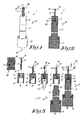
- figure 3 represents the successive steps of a possible method according to the invention;
- figures 4 to 7 represent possible variants of certain steps of the method according to the invention as represented in figure 3.
- The
brush 1 represented in figures 1 and 2 is a brush of the type as is used for example in a bottle of nail polish whereby the brush is fixed to thestopper 2 of the bottle concerned. - The
brush 1 is of the paint brush type with astick 3 and fibers orhairs 4, whereby thestick 3 is in this case made of two parts, namely a first part in the shape of anactual stick 5 and a second part in the shape of afiber holder 6 that is fixed to theactual stick 5 and that is provided with apassage 7 in which thefibers 4 are held in abundle 8. - In the given example, the
fiber holder 6 is made as a cap with acentral cavity 9 with which thefiber holder 6 is pushed over a narrowedend 10 of theactual stick 5 and is fixed to it, for example by means of gluing or other jointing techniques. - In the example, the diameter of the
fiber holder 6 is equal to the diameter of theactual stick 5, although this is not necessary. - The
fibers 4 stick with ashort end 10 in the above-mentionedcavity 8 and are connected there to said farends 10 by means of welding or gluing, such that thefibers 4 cannot be withdrawn from thefiber holder 6 and thefibers 4 freely protrude from the fiber holder over a certain length with their other farend 12. - The method according to the invention is simple and is illustrated by means of figure 3 in which the different steps of the method are shown, namely:
- step A : picking a
fiber bundle 8 from asupply 13 offibers 4, whereby the supply can be a spool from which thefibers 4 can be unwound, or it can be a cartridge of fibers that are pre-cut at length and whosefar ends 12 may be pre-treated so as to round off these farends 12 or the like; - step B : axially putting the picked-up
fiber bundle 8 through the above-mentionedpassage 7 of thefiber holder 6, in such a way that thefibers 4 stick in thecavity 9 of thefiber holder 6 with ashort end 11; - step C : melting the
far ends 11 of thefibers 4 together with amelting device 14 or gluing them together so as to prevent thefiber bundle 8 from being withdrawn from the fiber holder, in other words so as to prevent thefiber bundle 8 from being pushed out of thefiber holder 6 in at least one direction; - step D : providing and fixing the
fiber holder 6 on theactual stick 5 together with thefibers 4, for example by means of gluing, welding (friction welding, ultrasonic welding,...) or the like; - step E : optionally finishing the
free fiber ends 12 with afinishing device 15, for example by polishing or rounding off these farends 12. - Naturally, not necessarily all steps must be carried out in the same production site or at the same point in time. Thus, it is for example conceivable for the steps A, B and C to be carried out first so as to thus make a supply of
fiber holders 6 in which abundle 8 of fibers is fixed, and to carry out the steps D and E at another point in time and/or in a different location so as to obtain an entirely finishedbrush 1. - Figure 4 illustrates how, for example, step B can be carried out in an alternative way in three steps B1, B2 and B3, whereby use is made of an
intermediary support 16 with athrough hole 17 and apunch 18 in the shape of a pen which is provided in a shifting manner in aguide 19 and which can be shifted in the throughhole 17 of thesupport 16. - In step B1, the
fiber bundle 8 that has been picked up in step A is first provided in the throughhole 17 of thesupport 16. - In step B2, the
support 16 with the picked-upfiber bundle 8 is provided opposite afiber holder 6 with its throughhole 17 in line with thepassage 7 in thefiber holder 6 and in line with thepunch 18 which is also in line with thepassage 7 in thefiber holder 5. It is also possible that thesupport 16, when thefiber bundle 8 is being picked up, is already situated opposite thefiber holder 6, such that step B2 is redundant in that case. - In step B3, the
fiber bundle 8 is axially pushed from thesupport 16 in thepassage 7 of thefiber holder 6 into the position in which thefibers 4 stick in thecavity 9 with ashort end 11, by means of thepunch 18, such that these farends 11 can be connected to one another as explained in step C. - The
punch 18 can be provided with a straight or with apre-formed head 20 having another shape, so as to provide thefree end 21 of thefiber bundle 8 with a desired relief shape. - In the case of figure 4, the
punch 18 has arounded head 20, such that thefibers 4 can be pushed in deeper in the center of thebundle 8 than thefibers 4 on the outside of thebundle 8, as a result of which thefar end 21 of thefiber bundle 8 can be finished to a tub shape. - If necessary, use can be made of a counter-punch, not represented in the figures, which, as the
fiber bundle 8 is being pushed out of thesupport 16, is maintained behind thefiber holder 6 in the prolongation of thepunch 18. - According to yet another alternative method, as represented in figure 5,
several fiber bundles 8 are picked up, which are all provided in afiber holder 6 via asupport 16 with several throughholes 17 and anintermediate plate 22 with several conductingchannels 23 so as to form a composed fiber bundle, whereby the conductingchannels 23 to this end all open opposite the entry of thepassage 7 in thefiber holder 6. - If necessary, the conducting channels in figure 5 can be replaced by a single common funnel for the picked-up
bundles 8. - Another possibility for the
intermediate plate 22 is that, as a result of the design of the cross section of theconducting channels 23, the form of the picked-upfiber bundles 8 can be adjusted as desired. Naturally, in this application, an intermediate plate with only a single conductingchannel 23 can be applied as well. - Another possibility for adjusting the shape of the
fiber bundles 8 is by directly providing the through hole (17) in the support (16) with an adapted shape. - It is clear that the
support 16 and theintermediate plate 22 can be integrated as a whole. - Although, in the preceding figures, a
fiber holder 6 is represented which must be connected to theactual stick 5 by means of gluing or welding, also other jointing techniques can be applied, such as snapping on or in, whereby for example, as represented in figure 6,ribs 24 are provided in the narrowedend 10 of theactual stick 5 which can work in conjunction withcorresponding grooves 25 in the walls of thecavity 9 of thefiber holder 6. - Another possible jointing technique is the one whereby the
fiber holder 6 is pressed on or in theactual stick 5, either or not making use of ribs or overcuts or undercuts on the contact surfaces. - Figure 7 represents an example of a
brush 1 whereby thefiber holder 6 is made in the shape of a stopper which is pushed in anaxial recess 26 of theactual stick 5 and which is fixed in it by means of gluing, welding, pressing, shrinking, snapping or the like. - It is clear that certain steps of the method can also be carried out in another order.
- It is also clear that the
brushes 1 must not necessarily be made one by one, but that certain steps can be carried out simultaneously forseveral brushes 1. - The present invention is by no means limited to the method described as an example and represented in the accompanying drawings; on the contrary, such a method according to the invention for manufacturing brushes can be realized in all sorts of variants while still remaining within the scope of the invention.
Claims (15)
- Method for manufacturing a brush, in particular of the paint brush type with a stick (3) and fibers (4) or hairs, characterized in that the stick (3) is made of at least two loose parts, namely a first part in the shape of an actual stick (5) and a second part in the shape of a fiber holder (6) to be provided on the latter with a passage (7) in which the fibers (4) can be held, whereby the method consists in picking at least one fiber bundle (8) from a supply (13) of fibers (4), in axially providing the at least one fiber bundle (8) that has been picked up through the above-mentioned passage (7) of the fiber holder (6) in such a way that at least one fiber bundle (8) protrudes with both far ends (11-12) of the fibers (4) over a length from the passage (7), in melting or gluing together the far ends (11) of the fibers (4) on one far end (21) of the fiber bundle (8) so as to prevent the fiber bundle (8) from being withdrawn from the fiber holder (6), and in providing and fixing the fiber holder (6) together with the fibers (4) on the actual stick (5), either or not in another place and/or at another point in time.
- Method according to claim 1, characterized in that the fibers (4) that are picked up from the supply (13) have been pre-cut at length and/or have undergone a pretreatment such as rounding off or the like.
- Method according to claim 1 or 2, characterized in that the fiber holder (6) is made as a cap that is pushed over a far end (10) of the actual stick (5).
- Method according to any one of the preceding claims, characterized in that the fiber holder (6) is made as a cap with a cross section that is equal to the cross section of the actual stick (5) and which is pushed over a narrowed end (10) of the actual stick (5).
- Method according to any one of the preceding claims, characterized in that the fiber holder (6) is made as a stopper which is pushed in an axial recess (26) of the actual stick (5).
- Method according to any one of the preceding claims, characterized in that the fiber holder (6) is fixed on or in the actual stick (5) by means of a snap-in system.
- Method according to any one of the preceding claims, characterized in that the fiber holder (6) is fixed on or in the actual stick (5) by means of gluing or welding.
- Method according to any one of the preceding claims, characterized in that the fibers (4), after the fiber bundle (8) has been provided in the fiber holder (6), are subjected to a finishing operation such as rounding off the free fiber ends (12) or the like.
- Method according to any one of the preceding claims, characterized in that, before the picked-up fiber bundles (8) are applied, they are first provided in a support (16) with at least one through hole (17); in that this support (16) is provided with the picked-up fiber bundle (8) opposite the fiber holder (6) with its through hole (17) in the prolongation of the passage (7) in the fiber holder (6) and in that the fiber bundle (8) is axially pushed from the support (16) into the passage (7) of the fiber holder (6) by means of a punch (18) that can be shifted in the through hole (17) of the support (16).
- Method according to claim 9, characterized in that use is made of a punch (18) with a preformed head (20) so as to provide the free end (21) of the fiber bundle (8) with a desired relief shape.
- Method according to claim 9 or 10, characterized in that use is made of a counterpunch which, as the fiber bundle (8) is pushed out of the support (16), is maintained behind the fiber holder (6) in the prolongation of the punch (18).
- Method according to any one of claims 9 to 11, characterized in that an intermediate plate (22) is used which is put between the support (16) and the fiber holder (6) and which is provided with at least one conducting channel (23) which connects the through hole (17) of the support (16) to the passage (7) in the fiber holder (6).
- Method according to claim 12, characterized in that the shape of the cross section of the picked-up fiber bundle (8) is transformed, before being applied in the fiber holder (6), by providing a support (16) or intermediate plate (22) whereby the cross-sectional shape of its conducting channel (23) is adjusted to the desired shape of the final fiber bundle (8) of the brush (1).
- Method according to claim 12 or 13, characterized in that several fiber bundles (8) are picked up which are all provided in a fiber holder (6) of the brush (1), via a support (16) with several through holes (17) and an intermediate plate (22) with several conducting channels (23), so as to form a composed fiber bundle (8).
- Method according to any one of claims 12 to 14, characterized in that the support (16) and intermediate plate (22) are integrated as a whole.
Applications Claiming Priority (1)
| Application Number | Priority Date | Filing Date | Title |
|---|---|---|---|
| BE2006/0439A BE1017255A6 (en) | 2006-08-28 | 2006-08-28 | METHOD FOR MANUFACTURING BRUSHES |
Publications (2)
| Publication Number | Publication Date |
|---|---|
| EP1894489A2 true EP1894489A2 (en) | 2008-03-05 |
| EP1894489A3 EP1894489A3 (en) | 2010-03-17 |
Family
ID=38996436
Family Applications (1)
| Application Number | Title | Priority Date | Filing Date |
|---|---|---|---|
| EP07075670A Withdrawn EP1894489A3 (en) | 2006-08-28 | 2007-08-10 | Method for manufacturing brushes |
Country Status (3)
| Country | Link |
|---|---|
| US (1) | US20080048486A1 (en) |
| EP (1) | EP1894489A3 (en) |
| BE (1) | BE1017255A6 (en) |
Cited By (12)
| Publication number | Priority date | Publication date | Assignee | Title |
|---|---|---|---|---|
| WO2009127280A3 (en) * | 2008-04-16 | 2010-04-15 | G.B. Boucherie N.V. | Paintbrush |
| FR2955018A1 (en) * | 2010-01-11 | 2011-07-15 | Oreal | Device for application of e.g. cosmetic product such as mascara, on eyelashes and/or eyebrows, has applicator provided with series of hairs that are made of thermo fusible material, where end of applicator is connected to bundle of hairs |
| FR2955017A1 (en) * | 2010-01-11 | 2011-07-15 | Oreal | Applicator for use in conditioning and application device to apply i.e. cosmetic product, on eyelashes and/or eyebrows, has application unit provided with series of bristles, where additional application elements are different from bristles |
| EP2420157A1 (en) * | 2010-08-18 | 2012-02-22 | Trisa Holding AG | Toothbrush with brush topography structuring |
| US20120304407A1 (en) * | 2011-06-02 | 2012-12-06 | Hoipo Yu | Brush Head and Producing Device Thereof |
| USRE47468E1 (en) | 2001-12-28 | 2019-07-02 | Trisa Holding Ag | Toothbrush and process for producing such a toothbrush |
| US10405642B2 (en) | 2002-12-19 | 2019-09-10 | Trisa Holding Ag | Toothbrush and process for producing the same |
| WO2020068734A1 (en) * | 2018-09-24 | 2020-04-02 | Gunness Andrea | Makeup brush |
| EP3750442A1 (en) | 2019-06-13 | 2020-12-16 | Trisa Holding AG | Applicator device |
| US11219303B2 (en) | 2016-04-20 | 2022-01-11 | Trisa Holding Ag | Brush product and method for the production thereof |
| US11751676B2 (en) | 2018-09-24 | 2023-09-12 | Lumetique, Inc. | Makeup brush |
| US12075908B2 (en) | 2019-12-02 | 2024-09-03 | Lumetique, Inc. | Makeup brush |
Families Citing this family (1)
| Publication number | Priority date | Publication date | Assignee | Title |
|---|---|---|---|---|
| DE102019128360A1 (en) | 2018-10-22 | 2020-04-23 | Zahoransky Ag | Device and method for forming bristle bundles, brush manufacturing machine, use of a device for forming bristle bundles, brush, computer program and computer-readable medium |
Family Cites Families (7)
| Publication number | Priority date | Publication date | Assignee | Title |
|---|---|---|---|---|
| US2562716A (en) * | 1945-08-09 | 1951-07-31 | Rubberset Company | Brush and method of making same |
| US2652580A (en) * | 1947-02-24 | 1953-09-22 | Edwin A Neugass | Brush |
| US3992116A (en) * | 1973-03-05 | 1976-11-16 | Fomby Kenneth A | Applicator brush and method of making same |
| GB2159699B (en) * | 1984-05-23 | 1988-06-02 | Rodney David Cole | An applicator for the application of cosmetic products |
| DE19542393A1 (en) * | 1995-11-14 | 1997-05-15 | Zahoransky Anton Gmbh & Co | Making synthetic brushes esp tooth brushes |
| DE69915180T2 (en) * | 1998-07-14 | 2004-12-30 | Firma G.B. Boucherie N.V. | Method of making brushes and brush making machine for performing this method |
| DE10155473A1 (en) * | 2001-11-12 | 2003-06-05 | Boucherie Nv G B | Process for attaching bristle tufts to carrier plates |
-
2006
- 2006-08-28 BE BE2006/0439A patent/BE1017255A6/en not_active IP Right Cessation
-
2007
- 2007-08-10 EP EP07075670A patent/EP1894489A3/en not_active Withdrawn
- 2007-08-28 US US11/892,835 patent/US20080048486A1/en not_active Abandoned
Cited By (19)
| Publication number | Priority date | Publication date | Assignee | Title |
|---|---|---|---|---|
| USRE47468E1 (en) | 2001-12-28 | 2019-07-02 | Trisa Holding Ag | Toothbrush and process for producing such a toothbrush |
| US10405642B2 (en) | 2002-12-19 | 2019-09-10 | Trisa Holding Ag | Toothbrush and process for producing the same |
| US9498050B2 (en) | 2008-04-16 | 2016-11-22 | Gb Boucherie Nv | Paint brush |
| WO2009127280A3 (en) * | 2008-04-16 | 2010-04-15 | G.B. Boucherie N.V. | Paintbrush |
| FR2955018A1 (en) * | 2010-01-11 | 2011-07-15 | Oreal | Device for application of e.g. cosmetic product such as mascara, on eyelashes and/or eyebrows, has applicator provided with series of hairs that are made of thermo fusible material, where end of applicator is connected to bundle of hairs |
| FR2955017A1 (en) * | 2010-01-11 | 2011-07-15 | Oreal | Applicator for use in conditioning and application device to apply i.e. cosmetic product, on eyelashes and/or eyebrows, has application unit provided with series of bristles, where additional application elements are different from bristles |
| US10076181B2 (en) | 2010-08-18 | 2018-09-18 | Trisa Holding Ag | Toothbrush having a bristle area design |
| US9066579B2 (en) | 2010-08-18 | 2015-06-30 | Trisa Holding Ag | Process for producing a toothbrush having a bristle area design |
| WO2012022431A1 (en) * | 2010-08-18 | 2012-02-23 | Trisa Holding Ag | Toothbrush having a bristle area design |
| EP2420157A1 (en) * | 2010-08-18 | 2012-02-22 | Trisa Holding AG | Toothbrush with brush topography structuring |
| US20120304407A1 (en) * | 2011-06-02 | 2012-12-06 | Hoipo Yu | Brush Head and Producing Device Thereof |
| US11219303B2 (en) | 2016-04-20 | 2022-01-11 | Trisa Holding Ag | Brush product and method for the production thereof |
| WO2020068734A1 (en) * | 2018-09-24 | 2020-04-02 | Gunness Andrea | Makeup brush |
| GB2591043A (en) * | 2018-09-24 | 2021-07-14 | Gunness Andrea | Makeup brush |
| GB2591043B (en) * | 2018-09-24 | 2023-08-16 | Gunness Andrea | Makeup brush |
| US11751676B2 (en) | 2018-09-24 | 2023-09-12 | Lumetique, Inc. | Makeup brush |
| EP3750442A1 (en) | 2019-06-13 | 2020-12-16 | Trisa Holding AG | Applicator device |
| WO2020249618A2 (en) | 2019-06-13 | 2020-12-17 | Trisa Holding Ag | Applicator device |
| US12075908B2 (en) | 2019-12-02 | 2024-09-03 | Lumetique, Inc. | Makeup brush |
Also Published As
| Publication number | Publication date |
|---|---|
| US20080048486A1 (en) | 2008-02-28 |
| EP1894489A3 (en) | 2010-03-17 |
| BE1017255A6 (en) | 2008-05-06 |
Similar Documents
| Publication | Publication Date | Title |
|---|---|---|
| EP1894489A2 (en) | Method for manufacturing brushes | |
| US8308246B2 (en) | Method for manufacturing toothbrush and toothbrush manufactured by the method | |
| EP2422643A1 (en) | Tool for applying cosmetics | |
| EP3065593B1 (en) | Process and apparatus for creating tufts for tufted article | |
| CN113038853B (en) | Carrier for a bristle insert, brush and method for producing a brush | |
| CZ230897A3 (en) | Process and apparatus for producing brush articles and brush articles produced in such a manner and by making use of such apparatus | |
| TW201633961A (en) | Method for manufacturing a brush or bristles and apparatus for the same | |
| EP3449764B1 (en) | Environment-friendly and flocking hole-free paint brush and processing method therefor | |
| EP1211187A1 (en) | Device for cutting the remaining length of the tongue of a clamping ring | |
| EP1901632B1 (en) | Method for manufacturing brushes | |
| CN108621639A (en) | A kind of writing brush and preparation method thereof | |
| US9174267B2 (en) | Wire looping tool | |
| KR20120056311A (en) | Method for Manufacturing Toothbrush and Toothbrush Manufactured by the Mehtod | |
| EP1424017A3 (en) | Hair strand applicator | |
| JP4741921B2 (en) | Manufacturing method of mascara brush | |
| CN101999797A (en) | Brush, its manufacturing method and device | |
| US6260928B1 (en) | Handle Configuration for brush production by fusion | |
| EP1469975B1 (en) | Element with very high mechanical resistance and high vibration absorption and method for implementing the same | |
| JP4069623B2 (en) | Mascara brush | |
| JP4299285B2 (en) | Optical fiber connector assembly jig | |
| KR20200030204A (en) | Toothbrush manufacturing method utlizing toothbrush head kit | |
| US20050061350A1 (en) | Mascara brush | |
| KR100553446B1 (en) | How to fix hair bundles of cosmetic brushes | |
| JP2014033869A (en) | Interdental brush | |
| TWI867173B (en) | Bristle carrier, brush, and method for manufacturing the bristle carrier and the brush |
Legal Events
| Date | Code | Title | Description |
|---|---|---|---|
| PUAI | Public reference made under article 153(3) epc to a published international application that has entered the european phase |
Free format text: ORIGINAL CODE: 0009012 |
|
| AK | Designated contracting states |
Kind code of ref document: A2 Designated state(s): AT BE BG CH CY CZ DE DK EE ES FI FR GB GR HU IE IS IT LI LT LU LV MC MT NL PL PT RO SE SI SK TR |
|
| AX | Request for extension of the european patent |
Extension state: AL BA HR MK YU |
|
| PUAL | Search report despatched |
Free format text: ORIGINAL CODE: 0009013 |
|
| AK | Designated contracting states |
Kind code of ref document: A3 Designated state(s): AT BE BG CH CY CZ DE DK EE ES FI FR GB GR HU IE IS IT LI LT LU LV MC MT NL PL PT RO SE SI SK TR |
|
| AX | Request for extension of the european patent |
Extension state: AL BA HR MK RS |
|
| 17P | Request for examination filed |
Effective date: 20100907 |
|
| 17Q | First examination report despatched |
Effective date: 20101014 |
|
| AKX | Designation fees paid |
Designated state(s): BE CH DE ES IT LI |
|
| STAA | Information on the status of an ep patent application or granted ep patent |
Free format text: STATUS: THE APPLICATION IS DEEMED TO BE WITHDRAWN |
|
| 18D | Application deemed to be withdrawn |
Effective date: 20110225 |