EP1894043B1 - Licht reflektierendes tripel, reflektor sowie verfahren zur erkennung eines gegenstands - Google Patents
Licht reflektierendes tripel, reflektor sowie verfahren zur erkennung eines gegenstands Download PDFInfo
- Publication number
- EP1894043B1 EP1894043B1 EP06762106A EP06762106A EP1894043B1 EP 1894043 B1 EP1894043 B1 EP 1894043B1 EP 06762106 A EP06762106 A EP 06762106A EP 06762106 A EP06762106 A EP 06762106A EP 1894043 B1 EP1894043 B1 EP 1894043B1
- Authority
- EP
- European Patent Office
- Prior art keywords
- light
- reflector
- light reflecting
- triple prism
- triple
- Prior art date
- Legal status (The legal status is an assumption and is not a legal conclusion. Google has not performed a legal analysis and makes no representation as to the accuracy of the status listed.)
- Not-in-force
Links
Images


Classifications
-
- G—PHYSICS
- G02—OPTICS
- G02B—OPTICAL ELEMENTS, SYSTEMS OR APPARATUS
- G02B5/00—Optical elements other than lenses
- G02B5/12—Reflex reflectors
- G02B5/122—Reflex reflectors cube corner, trihedral or triple reflector type
- G02B5/124—Reflex reflectors cube corner, trihedral or triple reflector type plural reflecting elements forming part of a unitary plate or sheet
-
- E—FIXED CONSTRUCTIONS
- E01—CONSTRUCTION OF ROADS, RAILWAYS, OR BRIDGES
- E01F—ADDITIONAL WORK, SUCH AS EQUIPPING ROADS OR THE CONSTRUCTION OF PLATFORMS, HELICOPTER LANDING STAGES, SIGNS, SNOW FENCES, OR THE LIKE
- E01F9/00—Arrangement of road signs or traffic signals; Arrangements for enforcing caution
- E01F9/60—Upright bodies, e.g. marker posts or bollards; Supports for road signs
- E01F9/604—Upright bodies, e.g. marker posts or bollards; Supports for road signs specially adapted for particular signalling purposes, e.g. for indicating curves, road works or pedestrian crossings
- E01F9/619—Upright bodies, e.g. marker posts or bollards; Supports for road signs specially adapted for particular signalling purposes, e.g. for indicating curves, road works or pedestrian crossings with reflectors; with means for keeping reflectors clean
-
- G—PHYSICS
- G01—MEASURING; TESTING
- G01V—GEOPHYSICS; GRAVITATIONAL MEASUREMENTS; DETECTING MASSES OR OBJECTS; TAGS
- G01V8/00—Prospecting or detecting by optical means
- G01V8/10—Detecting, e.g. by using light barriers
- G01V8/12—Detecting, e.g. by using light barriers using one transmitter and one receiver
- G01V8/14—Detecting, e.g. by using light barriers using one transmitter and one receiver using reflectors
-
- G—PHYSICS
- G02—OPTICS
- G02B—OPTICAL ELEMENTS, SYSTEMS OR APPARATUS
- G02B27/00—Optical systems or apparatus not provided for by any of the groups G02B1/00 - G02B26/00, G02B30/00
- G02B27/28—Optical systems or apparatus not provided for by any of the groups G02B1/00 - G02B26/00, G02B30/00 for polarising
- G02B27/288—Filters employing polarising elements, e.g. Lyot or Solc filters
-
- G—PHYSICS
- G02—OPTICS
- G02B—OPTICAL ELEMENTS, SYSTEMS OR APPARATUS
- G02B5/00—Optical elements other than lenses
- G02B5/18—Diffraction gratings
- G02B5/1814—Diffraction gratings structurally combined with one or more further optical elements, e.g. lenses, mirrors, prisms or other diffraction gratings
Definitions
- the invention relates to a reflector, which consists of one or a plurality of triples and is preferably designed for use in the sensor, but also for road traffic and similar signaling tasks shows advantages.
- Reflective light barriers are used in sensor technology, in which most of the transmitter and receiver of the emitted light signal are in a housing and the emitted light falls on a reflector which reflects the light in the direction of the light source. To be sure that the received light is actually from the reflector and not from another light source or random reflection by another object, one preferably uses polarized light. The polarized light is rotated in a reflector formed by triples and reflected to the receiver. Due to the position of the polarization, the light signal can be identified as originating from the triple reflector. This safety device by evaluating the polarization direction of the reflected light is often ineffective today, because packaging films, for example, can generate random polarization directions of extraneous light on packets.
- personal protective clothing is often provided with reflective surfaces formed by small triples. These are also able to turn the light emitted by the light barrier so that the receiver in the light barrier is deceived. There is hardly any certainty that the received light signal actually comes from the targeted reflector.
- the object of the invention is to provide a sensor system which, when using a reflector, ensures that the received signal is actually derived from the targeted reflector.
- the reflector should also allow the previous polarization rotation in order to continue to apply the conventional detection method can.
- a reflector according to the invention which can modify the signal received by the sensor as a reflection.
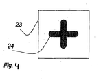
- This modified signal can be obtained using the diffraction method ( Fig. 4 to Fig. 7 ) even project any, preferably point-symmetrical figure.
- the transmitter of the sensor in function of a light barrier sends a light beam (light input signal) with, for example, 5 mm in diameter.
- the reflector according to the invention now responds with a modified light output signal which generates a clearly recognizable projection which the receiver can evaluate in the sensor.
- the evaluation of the projection obtained by the receiver of the sensor can easily be done on a cheap camera chip with a small number of pixels or simply on the arrangement of several individual receiving elements.
- the inventive method for the sensor is to receive the projection and useful at the same time with at least one pixel or a receiving element in addition to check whether outside the expected projection, a light signal is received. If that is the case, then the sensor detects that an external light or a foreign reflection is present.
- This principle of simultaneous positive testing namely to receive the expected projection, and the additional negative test, namely to observe a disturbance by extraneous light outside the expected projection where no light is allowed to make the method for the sensor reliably reliable.
- the size of the projection depends on the distance of the projection surface, ie the receiver of the sensor system, because the modified light output signal is based on trigonometric functions of the mirror surfaces in the triple. But for the practical use of light barriers over an observation distance of about 4 m, for example, for the projection of two points already used in the reflector low angle deviation from the right angle of two partial surfaces 2 and 3 of the triple to each other. So that in this example two clearly separated points are projected.
- the three sub-areas that form a triple are here called mirrors or mirror surfaces.
- the required angular deviation from the right angle of the second and third Spiegelfumbleen 2 and 3 to each other is already effective at about 2 to 120 minutes of arc as a similar positive or negative deviation from the right angle.
- a reflector which modifies the light signal striking it from the light source and reflects it toward the receiver of the sensor.
- the core idea of the reflector according to the invention is thus to change a light input signal incident on the reflector so that the reflector responds with a modified projection (light output signal). This feature allows the sensor technique to check whether the received light signal is in shape or different from the expected signal.
- the reflector consists of a triple ( Fig. 1 ) or preferably from a triple array ( Fig. 2 ).
- the triple array makes it possible to produce a larger reflective surface, which has the same effect over its entire surface.
- the triple array can be assembled from mutually twisted triplets or rows of triples, if the modified signal is to be projected in different positions with large-area illumination of triples of different positions.
- two or three modified signals or signal figures would then be projected in a twisted manner in accordance with the triple positions.
- the triple As a form of the triple almost all known reflection triplets can be used. However, it is preferable to the triple shapes that the cubic triple ( Fig. 1 ) come very close, so that as few interfering rays arise that could interfere with the presentation or detection of the double signal by additional light signals. By contrast, for example, the use of a pyramidal triple array would duplicate the double signal.
- the reflector according to the invention is very easy to use even in traffic. It makes it possible to send the incident headlights excellently in several directions at the same time.
- the reflector can be arranged so that the driver of a low passenger car and at the same time the driver of a high truck recognizes the reflector more clearly by the selected shape of the light projection of the reflector.
- triple arrays which are joined together from differently rotated triples or are provided with triples having different opening angles of the second and third mirror surfaces 2 and 3 according to the invention, a targeted light distribution can take place.
- a transparent film 25 overlies the light entrance surface of the triple and covers it by 50%.
- the characterization of the diffraction pattern in the film is omitted here to keep the presentation transparent to the reader.
- the first mirror 1c is half covered, the second mirror 2c is exposed, and the third mirror 3c is completely covered by the exemplary film.
- This transparent film contains a diffractive structure with a pixel size of, for example, 10 to 60 micrometers.
- the sensor sends a coherent light beam to the triple.
- the incident on the triple light thereof 50%, strikes the diffractive structure, penetrates into the glass body of the triple, meets the covered mirror surface 26 of the first mirror 1c or the third mirror 3c and is continuously retroflected over all three mirror.
- the light leaves the triple via the uncovered mirror face 27 of the first mirror 1c or the second mirror 2c, which is not covered by the exemplary foil.
- the light passes through the diffractive structure only once, although it passes through three mirrors in the triple. Only with the rule that the light penetrates the diffractive structure only once is a clean projection like in Fig. 4 possible.
- the cover of the triple chosen larger, it comes to blurring until finally the projection of only diffuse light. If the coverage chosen is less than 50% of the light entrance surface of the triple, then less irradiated sensor light takes part in the diffraction and there is the projection of the figure contained in the diffraction an interfering light spot or an over-radiation by non-diffractive light influenced.
- the diffractive structure can also be molded directly onto the light entry surface of the triple by introducing the diffractive structure directly into the surface of the plastic injection mold.
- Fig. 6 shows a Tripelarray 28, as a section of a plastic reflector with Fullcube triples.
- foils with a diffractive structure 29 are laid in strips in strip form over the triples, or the light entry surface of the reflector is preferably provided directly with a diffractive structure 29.
- the diffractive structures optimally cover 50% of the light entry surface of the triple. For reasons of clarity, the triple array and the diffractive structures are shown offset.
- the reflector according to the invention for the projection of a projection figure 24 produced by means of a diffractive structure, as in FIG Fig. 4 is shown after the in Fig. 5 covered with optimally 50% of its light entry surface.
- Fig. 7 shows a cover pattern for the triple.
- other cover patterns are also suitable for the individual triple, for example in the form of a three-bar cross, as on the warning signs for "Caution Radioactivity".
- the cover of the triple is designed, all six possible fundamental light paths through the triple should be such that the diffractive structure is optimally penetrated only once by the coherent light and that each cover part faces a free part in relation to the triple center.
- the triple 30 consists of the mirror part surfaces 31, 32, 33, 34 and 35, 36, wherein a first partial surface pair 31, 32 forms the first mirror, a second partial surface pair 33, 34 the second mirror and a third partial surface pair 35, 36 the third mirror ,
- the partial surfaces 31, 33, 35 are covered by a diffractive structure on the light entry surface, the partial surfaces 32, 34, 36 are free.
- a reflection light barrier sends light onto a reflector.
- the reflector does not respond with the shape of the received light signal, but responds with a double signal projecting two light centers.
- the reflector may also be such that it responds with a different geometric figure than light projection.
- the modified-signal reflector makes it possible to design a sensor system which can verify, by evaluating the light signal received by the reflector, whether the received signal originates from the reflector or from a foreign light source or from a foreign reflection.
Landscapes
- Physics & Mathematics (AREA)
- General Physics & Mathematics (AREA)
- Optics & Photonics (AREA)
- Civil Engineering (AREA)
- Geophysics (AREA)
- Engineering & Computer Science (AREA)
- Architecture (AREA)
- Life Sciences & Earth Sciences (AREA)
- Structural Engineering (AREA)
- General Life Sciences & Earth Sciences (AREA)
- Geophysics And Detection Of Objects (AREA)
- Investigating Or Analysing Materials By Optical Means (AREA)
- Optical Elements Other Than Lenses (AREA)
- Holo Graphy (AREA)
- Silicon Polymers (AREA)
- Golf Clubs (AREA)
- Investigating, Analyzing Materials By Fluorescence Or Luminescence (AREA)
Description
- Die Erfindung betrifft einen Reflektor, der aus einem oder einer Vielzahl von Tripeln besteht und bevorzugt für die Verwendung in der Sensorik gestaltet ist, jedoch auch für den Straßenverkehr und ähnliche Signalaufgaben Vorteile zeigt.
- In der Sensorik werden Reflexions-Lichtschranken verwendet, bei denen meist Sender und Empfänger des ausgesandten Lichtsignals in einem Gehäuse sind und das ausgesandte Licht auf einen Reflektor fällt, der das Licht in Richtung der Lichtquelle reflektiert. Um sicher zu gehen, das das empfangene Licht tatsächlich vom Reflektor stammt und nicht von einer anderen Lichtquelle oder zufälligen Reflexion durch einen anderen Gegenstand, verwendet man bevorzugt polarisiertes Licht. Das polarisierte Licht wird in einem aus Tripeln gebildeten Reflektor gedreht und zum Empfänger reflektiert. Durch die Lage der Polarisation lässt sich das Lichtsignal als vom Tripelreflektor stammend identifizieren. Diese Sicherheitseinrichtung durch Auswertung der Polarisationsrichtung des reflektierten Lichtes wird heute oft wirkungslos, weil auch Verpackungsfolien zum Beispiel auf Paketen zufällige Polarisationsrichtungen von Fremdlicht erzeugen können. Hinzu kommt, dass Sicherheitskleidung von Personen oft mit reflektierenden Flächen versehen ist, die aus kleinen Tripeln gebildet sind. Diese vermögen ebenfalls das von der Lichtschranke ausgesendete Licht zu drehen, so dass der Empfänger in der Lichtschranke getäuscht wird. Es besteht kaum noch Sicherheit, dass das empfangene Lichtsignal tatsächlich vom angepeilten Reflektor stammt.
- Die Aufgabe der Erfindung ist die Schaffung eines Sensorsystems, das bei Verwendung eines Reflektors sicher stellt, dass das empfangene Signal tatsächlich von dem angepeilten Reflektor stammt. Zusätzlich soll der Reflektor auch die bisherige Polarisationsdrehung ermöglichen, um auch die herkömmliche Detektionsmethode weiter anwenden zu können.
- Um diese neue Sensorik zur Beobachtung von Projektionen anwenden zu können, wird ein erfindungsgemäßer Reflektor vorgeschlagen, der als Reflexion das von der Sensorik eingetroffene Signal modifizieren kann. Dieses modifizierte Signal kann bei Verwendung der Diffraktionsmethode (
Fig. 4 bis Fig. 7 ) sogar eine beliebige, bevorzugt punktsymmetrische Figur projizieren. - Das Verfahren für die Sensorik.
- Der Sender der Sensorik in Funktion einer Lichtschranke sendet ein Lichtstrahlbündel (Lichteingangssignal) mit zum Beispiel 5 mm Durchmesser. Der erfindungsgemäße Reflektor antwortet nun mit einem modifizierten Lichtausgangssignal, das eine deutlich erkennbare Projektion erzeugt, die der Empfänger im Sensor auswerten kann. Die Auswertung der vom Empfänger der Sensorik erhaltenen Projektion kann einfach über einen preiswerten Kamerachip erfolgen mit einer geringen Zahl von Pixeln oder einfach über die Anordnung mehrerer einzelner Empfangselemente.
- Das erfindungsgemäße Verfahren für die Sensorik ist, die Projektion zu empfangen und zweckmäßig zugleich mit mindestens einem Pixel oder einem Empfangselement zusätzlich zu prüfen, ob außerhalb der erwarteten Projektion ein Lichtsignal empfangen wird. Wenn das nämlich der Fall ist, dann erkennt die Sensorik, dass ein Fremdlicht oder eine fremde Reflexion vorliegt. Dieses Prinzip der gleichzeitigen Positivprüfung, nämlich die erwartete Projektion zu empfangen, und der zusätzlichen Negativprüfung, nämlich eine Störung durch Fremdlicht außerhalb der erwarteten Projektion zu beobachten, wo kein Licht eintreffen darf, macht das Verfahren für die Sensorik so zuverlässig sicher.
- Nachfolgend wird am wiederkehrenden Beispiel der Winkelmethode (
Fig. 1 bis Fig. 3 ) eine einfache Projektion von zwei Punkten gewählt, um Details erläutern zu können. - Der Größe der Projektion ist abhängig vom Abstand der Projektionsfläche, also des Empfängers der Sensorik, weil das modifizierte Lichtausgangssignal auf Winkelfunktionen der Spiegelflächen im Tripel beruht. Aber für den praktischen Einsatz von Lichtschranken über einen Beobachtungsabstand von etwa 4 m genügt zum Beispiel für die Projektion zweier Punkte bereits eine im Reflektor verwendete geringe Winkelabweichung vom Rechten Winkel zweier Teilflächen 2 und 3 des Tripels zueinander. So dass in diesem Beispiel zwei deutlich getrennte Punkte projiziert werden.
- Die drei Teilflächen, die einen Tripel bilden, werden hier nachfolgend Spiegel bzw. Spiegelflächen genannt. Die erforderliche Winkelabweichung vom Rechten Winkel der zweiten und dritten Spiegelfächen 2 und 3 zueinander ist bereits bei etwa 2 bis 120 Bogenminuten als gleichartige positive oder negative Abweichung vom Rechten Winkel deutlich wirksam.
- Der erfindungsgemäße Reflektor.
- Es wird ein Reflektor vorgeschlagen, der das von der Lichtquelle auf ihn treffende Lichtsignal modifiziert und in Richtung zum Empfänger des Sensors reflektiert.
- Der Kerngedanke des erfindungsgemäßen Reflektors ist also, ein auf den Reflektor einfallendes Lichteingangssignal so zu verändern, dass der Reflektor mit einer modifizierten Projektion (Lichtausgangssignal) antwortet. Diese Eigenschaft ermöglicht dem Verfahren zur Sensorik zu prüfen, ob das empfangene Lichtsignal in seiner Form dem erwarteten Signal entspricht oder davon abweicht.
- Der Reflektor besteht aus einem Tripel (
Fig. 1 ) oder vorzugsweise aus einem Tripelarray (Fig. 2 ). Das Tripelarray ermöglicht die Herstellung einer größeren Reflexfläche, die über ihre gesamte Fläche die gleichartige Wirkung zeigt. - Außerdem kann das Tripelarray aus zueinander verdrehten Tripeln oder Reihen von Tripeln zusammengefügt werden, wenn bei großflächiger Beleuchtung von Tripeln unterschiedlicher Stellung das modifizierte Signal in unterschiedlichen Stellungen projiziert werden soll. So würden dann zum Beispiel zwei oder drei modifizierte Signale oder Signalfiguren entsprechend der Tripelstellungen zueinander verdreht projiziert werden.
- Als Form des Tripels können nahezu alle bekannten Reflexionstripel verwendet werden. Es sind aber die Tripelformen zu bevorzugen, die dem kubischen Tripel (
Fig. 1 ) besonders nahe kommen, damit möglichst wenige Störstrahlen entstehen, die die Darstellung oder Erkennung des Doppelsignals durch zusätzliche Lichtsignale stören könnten. Dagegen würde zum Beispiel durch die Verwendung eines pyramidalen Tripelarrays das Doppelsignal mehrfach abgebildet werden. - Der erfindungsgemäße Reflektor ist auch im Straßenverkehr sehr gut verwendbar. Ermöglicht er doch, das einfallende Scheinwerferlicht hervorragend in mehrere Richtungen zugleich zu senden. So kann der Reflektor so angeordnet werden, dass der Fahrer eines niedrigen Personenkraftwagens und zugleich der Fahrer eines hohen Lastkraftwagens den Reflektor deutlicher erkennt durch die gewählte Gestalt der Lichtprojektion des Reflektors.
- Bei Tripelarrays, die aus verschieden gedrehten Tripeln zusammengefügt sind oder aus erfindungsgemäßen Tripeln mit unterschiedlichen Öffnungswinkeln der zweiten und dritten Spiegelfläche 2 und 3 versehen sind, kann eine gezielte Lichtverteilung erfolgen.
- Im Folgenden wird die Erfindung anhand der in der Zeichnung schematisch dargestellten Ausführungsbeispiele näher erläutert:
- Die
Fig. 1 bis Fig. 3 veranschaulichen die Winkelmethode. - Die
Fig. 4 bis Fig. 7 veranschaulichen die Diffraktionsmethode. - Mittels der Figuren lassen sich die unterschiedlichen Ausbildungen des erfindungsgemäßen Reflektors und des dazu gehörigen Verfahrens für die Sensorik nachfolgend erläutern.
- Es zeigt die
-
Fig. 1 einen so genannten Fullcube-Tripel, der in der Idealform aus drei quadratischen Teilflächen, nämlich der ersten, der zweiten und der dritten Spiegelfläche 1, 2, 3 bestehen würde mit dem Tripelzentrum 4. In der Idealform würden die drei Spiegel zueinander im Rechten Winkel stehen. Der erfindungsgemäße Reflektor weicht davon ab.
Die zweite und die dritte Spiegelfläche 2 und 3 bilden einen Öffnungswinkel von größer oder kleiner 90°, bevorzugt von größer 90°. Sie stehen aber im Rechten Winkel zur ersten Spiegelfläche 1. In der Fertigungspraxis gibt es natürlich Toleranzen, so dass der hier bezeichnete Rechte Winkel geringfügig abweichen könnte.
Die Kanten 5 und 6 begrenzen die zweite Spiegelfläche 2, die Kanten 6 und 7 begrenzen die dritte Spiegelfläche 3. -
Fig. 2 zeigt ein Tripelarray, gebildet aus den Tripeln derFig. 1 . Dieses Tripelarray hat den Vorzug, eine große Fläche für das auftreffende Lichtsignal bereit zu stellen. Wird zum Beispiel ein Laserlicht verwendet, das über größere Entfernungen schwer auszurichten ist, so bietet das Tripelarray eine vergrößerte Zielfläche. Da in diesem Beispiel alle Tripel von gleicher Beschaffenheit sind, wird das Tripelarray immer gleichartig das Licht modifizieren und reflektieren unabhängig davon, wo der Laserstrahl auf dem Tripelarray auftrifft. -
Fig. 3 zeigt eine Lichtempfangsfläche 9 für das reflektierte Licht und eine beispielhafte Projektion des vom Reflektor erzeugten Doppelsignals. Angenommen wird, dass hinter der teiltransparenten Lichtempfangsfläche 9 im Zentrum 10 ein Lichtsender angeordnet ist, der zum Beispiel kohärentes Licht in Form eines kreisrunden Lichtstrahles zum erfindungsgemäßen Reflektor sendet. Der Reflektor beantwortet nun dieses Lichteingangssignal mit zwei deutlich getrennten Lichtzentren 11 und 12 als Lichtausgangssignal, die er auf die Lichtempfangsfläche projiziert. -
Fig. 4 zeigt eine Projektionsfläche 23, auf der ein durch die erfindungsgemäße Diffraktionsmethode erzeugtes Kreuzsymbol 24 erscheint. Allerdings muss dazu das vom Sensor ausgesandte Licht kohärent sein. Mittels der Diffraktion können nun nahezu alle denkbaren Projektionsmuster erzeugt werden. Aber auch hier ist für die Gestaltung des Reflektors eine weitere erfindungsgemäße Lehre zu beachten, die inFig. 5 erläutert wird. -
Fig. 5 zeigt einen Fullcube-Tripel mit einer ersten, einer zweiten und einer dritten Spiegelfläche 1c, 2c und 3c. Alle Spiegel stehen in diesem Beispiel zueinander im Rechten Winkel. Die Spiegel können aber auch andere Winkel oder Formate besitzen. Für die Erläuterung der erfindungsgemäßen Diffraktionsmethode sind die Tripelvariationen hier nicht von Bedeutung. - Eine transparente Folie 25 liegt über der Lichteintrittsfläche des Tripels und bedeckt ihn zu 50%. Auf die Kennzeichnung des Diffraktionsmusters in der Folie wird hier verzichtet, um die Darstellung für den Leser durchsichtig zu halten.
- Der erste Spiegel 1c ist zur Hälfte abgedeckt, der zweite Spiegel 2c liegt frei und der dritte Spiegel 3c ist vollständig von der beispielhaften Folie abgedeckt. Diese transparente Folie enthält eine diffraktive Struktur mit einer Pixelgröße von beispielhaft 10 bis 60 Mikrometer. Der Sensor sendet ein kohärentes Lichtbündel zum Tripel. Das auf den Tripel eintreffende Licht, davon 50%, trifft auf die diffraktive Struktur, dringt in den Glaskörper des Tripels ein, trifft auf die abgedeckte Spiegelteilfläche 26 des ersten Spiegels 1c oder den dritten Spiegel 3c und wird über alle drei Spiegel laufend retroflektiert. Das Licht verlässt den Tripel über die nicht abgedeckte Spiegelteilfläche 27 des ersten Spiegels 1c oder den zweiten Spiegel 2c, welcher nicht von der beispielhaften Folie abgedeckt ist.
- Weitere 50% des vom Sensor eintreffenden Lichtes trifft auf die von der Folie nicht abgedeckte Spiegelteilfläche 27 und den zweiten Spiegel 2c und verlässt den Tripel über jene Spiegelteilfläche 26 und Spiegel 3c, die von der Folie abgedeckt sind.
- Bei allen sechs möglichen Lichtwegen durchläuft das Licht die diffraktive Struktur nur einmal, obwohl es im Tripel über drei Spiegel läuft. Nur mit der Regel, dass das Licht die diffraktive Struktur nur einmal durchdringt, ist eine saubere Projektion wie in
Fig. 4 möglich. - Würde die Abdeckung des Tripels größer gewählt, kommt es zu Unschärfen bis schließlich zur Projektion ausschließlich diffusen Lichtes. Wird die Abdeckung kleiner als 50% der Lichteintrittsfläche des Tripels gewählt, dann nimmt weniger eingestrahltes Sensorlicht an der Diffraktion teil und es entsteht zu der Projektion der in der Diffraktion enthaltenen Figur ein störender Lichtfleck oder eine Überstrahlung durch nicht-diffraktiv beeinflusstes Licht.
- Anstelle einer Diffraktionsfolie 25 kann auch die diffraktive Struktur direkt auf die Lichteintrittsfläche des Tripels abgeformt werden, indem die diffraktive Struktur direkt in die Oberfläche der Kunststoffspritzgussform eingebracht ist.
- Das kann durch Einlegen einer Nickelabformung in die Form erfolgen. Die praktische Anwendung der erfindungsgemäßen Diffraktionsmethode für Kunststoffreflektoren, die aus einer Vielzahl von Tripeln bestehen, zeigt die folgende Figur.
-
Fig. 6 zeigt ein Tripelarray 28, als Ausschnitt aus einem Kunststoffreflektor mit Fullcube-Tripeln. Über die Tripel sind streifenförmig zum Beispiel Folien mit diffraktiver Struktur 29 gelegt, oder bevorzugt ist die Lichteintrittsfläche des Reflektors direkt mit einer diffraktiven Struktur 29 versehen. Die diffraktiven Strukturen bedecken optimal 50% der Lichteintrittsfläche der Tripel. Aus Gründen der verständlicheren Darstellung sind das Tripelarray und die diffraktiven Strukturen versetzt dargestellt. - Der erfindungsgemäße Reflektor für die Projektion einer mittels einer diffraktiven Struktur erzeugten Projektionsfigur 24, wie in
Fig. 4 gezeigt, wird also nach der inFig. 5 dargelegten Regel mit optimal 50% seiner Lichteintrittsfläche bedeckt. -
Fig. 7 zeigt ein Abdeckungsmuster für den Tripel. Neben der streifenförmigen Abdeckung sind auch andere Abdeckungsmuster für den einzelnen Tripel geeignet, zum Bespiel in Form eines Dreibalkenkreuzes, wie auf den Warnschildern für "Vorsicht Radioaktivität". Wie auch immer die Abdeckung des Tripels gestaltet wird, sollten alle sechs möglichen grundsätzlichen Lichtwege durch den Tripel so verlaufen, dass die diffraktive Struktur optimal nur einmal vom kohärenten Licht durchdrungen wird und dass jedem Abdeckungsteil ein freier Teil in Bezug über das Tripelzentrum gegenüberliegt. - Der Tripel 30 besteht aus den Spiegelteilflächen 31, 32, 33, 34 und 35, 36, wobei ein erstes Teilflächenpaar 31, 32 den ersten Spiegel, ein zweites Teilflächenpaar 33, 34 den zweiten Spiegel und ein drittes Teilflächenpaar 35, 36 den dritten Spiegel bildet.
- Die Teilflächen 31, 33, 35 sind durch eine diffraktive Struktur auf der Lichteintrittsfläche abgedeckt, die Teilflächen 32, 34, 36 sind frei.
- Zusammenfassend ist folgendes festzuhalten:
- Eine Reflexionslichtschranke sendet Licht auf einen Reflektor. Der Reflektor antwortet nicht mit der Form des erhaltenen Lichtsignals, sondern antwortet mit einem Doppelsignal, das zwei Lichtzentren projiziert. Der Reflektor kann auch so beschaffen sein, dass er mit einer anderen geometrischen Figur als Lichtprojektion antwortet. Der Reflektor mit modifiziertem Signal ermöglicht ein Sensorsystem zu gestalten, das durch die Auswertung des vom Reflektor empfangenen Lichtsignals verifizieren kann, ob das empfangene Signal vom Reflektor oder von einer fremden Lichtquelle oder von einer fremden Reflexion stammt.
Claims (16)
- Licht reflektierendes Tripel mit einer ersten, einer zweiten und einer dritten Spiegelfläche (1, 2, 3; 1 c, 2c, 3c), wobei seine Lichteintrittsfläche teilweise mit einem transparenten, ein Diffraktionsmuster aufweisenden Abdeckelement (25) bedeckt ist, dadurch gekennzeichnet, dass das Abdeckelement (25) die Hälfte der Lichteintrittsfläche bedeckt und dass einer abgedeckten Teilfläche des Tripels im Strahlengang eine nicht abgedeckte Teilfläche so gegenüberliegt, dass das Licht das Abdeckelement (25) höchstens einmal durchdringt.
- Licht reflektierendes Tripel nach Anspruch 1, dadurch gekennzeichnet, dass die erste Spiegelfläche (1, 1 c) zur Hälfte und die dritte Spiegelfläche (3, 3c) vollständig durch das Abdeckelement (25) abgedeckt sind.
- Licht reflektierendes Tripel nach Anspruch 2, dadurch gekennzeichnet, dass das Abdeckelement (25) eine mit der Kante zwischen der zweiten und der dritten Spiegelfläche (2, 3; 2c, 3c) deckungsgleiche Begrenzungslinie aufweist.
- Licht reflektierendes Tripel nach Anspruch 1, dadurch gekennzeichnet, dass jede der Spiegelflächen (1, 2, 3; 1 c, 2c, 3c) zur Hälfte durch das Abdeckelement abgedeckt sind.
- Licht reflektierendes Tripel nach einem der vorangehenden Ansprüche, dadurch gekennzeichnet, dass die erste und die zweite Spiegelfläche (1, 2; 1 c, 2c) sowie die erste und die dritte Spiegelfläche (1, 3; 1 c, 3c) aufeinander senkrecht stehen, dass die zweite und die dritte Spiegelfläche (2, 3; 2c, 3c) in einem von 90° verschiedenen Winkel zueinander angeordnet sind, und dass die zweite und die dritte Spiegelfläche (2, 3; 2c, 3c) identische Größe und Form aufweisen.
- Licht reflektierendes Tripel nach einem der vorangehenden Ansprüche, dadurch gekennzeichnet, dass die zweite und die dritte Spiegelfläche (2, 3; 2c, 3c) jeweils quadratisch sind.
- Licht reflektierendes Tripel nach einem der Ansprüche 5 oder 6, dadurch gekennzeichnet, dass die zweite und die dritte Spiegelfläche (2, 3; 2c, 3c) in einem Winkel zueinander angeordnet sind, der mindestens eine Minute und höchstens neun Grad vom rechten Winkel abweicht.
- Licht reflektierendes Tripel nach einem der vorangehenden Ansprüche, dadurch gekennzeichnet, dass es aus Glas, wie Floatglas, Borosilikatglas oder Quarzglas, oder aus Kunststoff, wie Polymethylmethacrylat (PMMA), Polyvinylchlorid (PVC), Polycarbonat (PC) oder Styrol gefertigt ist.
- Licht reflektierendes Tripel nach einem der Ansprüche 1 bis 7, dadurch gekennzeichnet, dass es aus Metall, wie Gold, Silber, Aluminium, Nickel, Messing, Kupfer, Bronze, Neusilber, Titan, Blei oder Stahl, oder durch Bedampfen eines formgebenden Tragekörpers aus Kunststoff, Glas oder Metall mit einem der vorgenannten Werkstoffe gefertigt ist.
- Licht reflektierendes Tripel nach einem der vorangehenden Ansprüche, dadurch gekennzeichnet, dass es an seiner Lichteintrittsfläche einen Polarisationsfilter aufweist.
- Reflektor mit einer Vielzahl von Licht reflektierenden Tripeln nach einem der vorangehenden Ansprüche.
- Reflektor nach Anspruch 11, dadurch gekennzeichnet, dass die Tripelachsen der Licht reflektierenden Tripel in mindestens zwei verschiedenen Orientierungen angeordnet sind.
- Reflektor nach Anspruch 11 oder 12, dadurch gekennzeichnet, dass die zweiten und die dritten Spiegelflächen (2, 3; 2c, 3c) in mindestens zwei verschiedenen Winkeln zueinander angeordnet sind.
- Verfahren zur Erkennung eines mit einem Licht reflektierenden Tripel nach einem der Ansprüche 1 bis 10 oder einem Reflektor nach einem der Ansprüche 11 bis 13 versehenen Gegenstands, wobei mittels einer Lichtquelle ein Lichteingangssignal auf den Gegenstand gesandt wird und wobei mittels eines Detektors auf einer Lichtempfangsfläche (10; 23) ein reflektiertes Lichtausgangssignal erfasst und mit einem gespeicherten Sollsignal verglichen wird.
- Verfahren nach Anspruch 14, dadurch gekennzeichnet, dass der Gegenstand als erkannt gilt, wenn das Lichtausgangssignal mit dem Sollsignal übereinstimmt.
- Verfahren nach Anspruch 14, dadurch gekennzeichnet, dass der Gegenstand als erkannt gilt, wenn das Lichtausgangssignal mit dem Sollsignal übereinstimmt und ein weiteres gespeichertes Sollsignal nicht erfasst wird.
Applications Claiming Priority (2)
| Application Number | Priority Date | Filing Date | Title |
|---|---|---|---|
| DE102005063331A DE102005063331A1 (de) | 2005-06-23 | 2005-06-23 | Licht reflektierendes Tripel, Reflektor sowie Verfahren zur Erkennung eines Gegenstands |
| PCT/EP2006/005932 WO2006136381A2 (de) | 2005-06-23 | 2006-06-21 | Licht reflektierendes tripel, reflektor sowie verfahren zur erkennung eines gegenstands |
Publications (2)
| Publication Number | Publication Date |
|---|---|
| EP1894043A2 EP1894043A2 (de) | 2008-03-05 |
| EP1894043B1 true EP1894043B1 (de) | 2008-11-05 |
Family
ID=37450993
Family Applications (1)
| Application Number | Title | Priority Date | Filing Date |
|---|---|---|---|
| EP06762106A Not-in-force EP1894043B1 (de) | 2005-06-23 | 2006-06-21 | Licht reflektierendes tripel, reflektor sowie verfahren zur erkennung eines gegenstands |
Country Status (5)
| Country | Link |
|---|---|
| US (1) | US7717575B2 (de) |
| EP (1) | EP1894043B1 (de) |
| AT (1) | ATE413615T1 (de) |
| DE (2) | DE102005063331A1 (de) |
| WO (1) | WO2006136381A2 (de) |
Cited By (1)
| Publication number | Priority date | Publication date | Assignee | Title |
|---|---|---|---|---|
| DE102020004967A1 (de) | 2020-08-14 | 2022-02-17 | IMOS Gubela Gesellschaft mit beschränkter Haftung | Retroreflektierendes Element mit einem Sicherheitselement |
Families Citing this family (10)
| Publication number | Priority date | Publication date | Assignee | Title |
|---|---|---|---|---|
| DE102006027389B4 (de) * | 2006-06-13 | 2019-07-04 | Sick Ag | Lichtschranke und Verfahren zu deren Betrieb |
| DE102007006405B4 (de) | 2007-02-05 | 2012-02-16 | Imos Gubela Gmbh | Reflektor mit einer Trapez-Reflexion und Verfahren für die Licht-Feinabtastung zur Erkennung eines Gegenstandes |
| USD810323S1 (en) * | 2014-02-04 | 2018-02-13 | Federico Gigli | Tile |
| DE102018112043B4 (de) * | 2018-05-18 | 2022-01-13 | Hans-Erich Gubela | Anordnung eines Retroreflektors mit Optikelementen |
| US20210231939A1 (en) | 2018-06-04 | 2021-07-29 | Jenoptik Optical Systems Gmbh | Microscope and method for capturing a microscopic image and use of a planar reflector |
| USD975452S1 (en) * | 2021-03-18 | 2023-01-17 | Trias Holding Ag | Fabric |
| USD1061952S1 (en) * | 2022-05-17 | 2025-02-11 | Elmdene Group, Ltd. | Tessellating board |
| USD1061955S1 (en) * | 2022-05-17 | 2025-02-11 | Elmdene Group, Ltd. | Tessellating board |
| USD1061953S1 (en) * | 2022-05-17 | 2025-02-11 | Elmdene Group, Ltd. | Tessellating board |
| USD1061954S1 (en) * | 2022-05-17 | 2025-02-11 | Elmdene Group, Ltd. | Tessellating board |
Family Cites Families (13)
| Publication number | Priority date | Publication date | Assignee | Title |
|---|---|---|---|---|
| US1743835A (en) | 1923-07-09 | 1930-01-14 | Jonathan C Stimson | Reflecting device |
| US1671086A (en) | 1923-07-09 | 1928-05-22 | Jonathan C Stimson | Reflecting device |
| US1743834A (en) | 1925-07-29 | 1930-01-14 | Jonathan C Stimson | Reflecting device |
| US2472782A (en) | 1945-09-07 | 1949-06-14 | Bell Telephone Labor Inc | Wave modifying reflector |
| FR1240121A (fr) | 1959-07-29 | 1960-09-02 | E Manducher & Co Sa | Catadioptre tétraédrique translucide à grand champ |
| US3833285A (en) | 1973-05-22 | 1974-09-03 | Amerace Esna Corp | Retrodirective reflector visible over wide range of observation angles |
| US5171624A (en) | 1990-06-01 | 1992-12-15 | Reflexite Corporation | Retroreflective microprismatic material and method of making same |
| DE4029766A1 (de) | 1990-09-20 | 1992-04-02 | Leuze Electronic Gmbh & Co | Reflexionslichtschranke |
| JPH0782122B2 (ja) | 1991-04-17 | 1995-09-06 | 国立環境研究所長 | キューブコーナーリトロリフレクター |
| US5656360A (en) | 1996-02-16 | 1997-08-12 | Minnesota Mining And Manufacturing Company | Article with holographic and retroreflective features |
| US6353489B1 (en) * | 2000-11-23 | 2002-03-05 | Digilens, Inc. | Optical retro-reflection device |
| DE10119671A1 (de) | 2001-04-20 | 2002-10-24 | Sen Hans-Erich Gubela | Umlenkspiegelstruktur, bestehend aus einer Vielzahl von Tripeln |
| DE10228013B4 (de) | 2002-06-22 | 2005-11-03 | Hans-Erich Sen. Gubela | Teiltransmissionsreflektor, Verwendung des Teiltransmissionsreflektors und optisches Sensorsystem |
-
2005
- 2005-06-23 DE DE102005063331A patent/DE102005063331A1/de not_active Ceased
-
2006
- 2006-06-21 WO PCT/EP2006/005932 patent/WO2006136381A2/de not_active Ceased
- 2006-06-21 AT AT06762106T patent/ATE413615T1/de active
- 2006-06-21 DE DE502006002023T patent/DE502006002023D1/de active Active
- 2006-06-21 US US11/922,641 patent/US7717575B2/en not_active Expired - Fee Related
- 2006-06-21 EP EP06762106A patent/EP1894043B1/de not_active Not-in-force
Cited By (5)
| Publication number | Priority date | Publication date | Assignee | Title |
|---|---|---|---|---|
| DE102020004967A1 (de) | 2020-08-14 | 2022-02-17 | IMOS Gubela Gesellschaft mit beschränkter Haftung | Retroreflektierendes Element mit einem Sicherheitselement |
| EP3958025A2 (de) | 2020-08-14 | 2022-02-23 | IMOS Gubela GmbH | Retroreflektierendes element mit einem sicherheitselement |
| EP4016143A2 (de) | 2020-08-14 | 2022-06-22 | IMOS Gubela GmbH | Verfahren zur ausrichtung eines retroreflektierenden elements mit einem sicherheitselement |
| US12043055B2 (en) | 2020-08-14 | 2024-07-23 | Hans-Erich Gubela, JR. | Retroreflective element having a security element |
| DE102020004967B4 (de) | 2020-08-14 | 2024-08-01 | Hans-Erich Gubela | Retroreflektierendes Element mit einem Sicherheitselement |
Also Published As
| Publication number | Publication date |
|---|---|
| WO2006136381A2 (de) | 2006-12-28 |
| US20090097118A1 (en) | 2009-04-16 |
| ATE413615T1 (de) | 2008-11-15 |
| US7717575B2 (en) | 2010-05-18 |
| DE502006002023D1 (de) | 2008-12-18 |
| WO2006136381A3 (de) | 2007-03-22 |
| EP1894043A2 (de) | 2008-03-05 |
| DE102005063331A1 (de) | 2006-12-28 |
Similar Documents
| Publication | Publication Date | Title |
|---|---|---|
| EP1894043B1 (de) | Licht reflektierendes tripel, reflektor sowie verfahren zur erkennung eines gegenstands | |
| EP3918248B1 (de) | Funktionalisierter wellenleiter für ein detektorsystem | |
| EP3918250B1 (de) | Funktionalisierter wellenleiter für ein detektorsystem | |
| DE102007027429B4 (de) | Radareinrichtung und optischer Empfänger dafür | |
| DE202018100323U1 (de) | LIDAR-Sensorfensterkonfiguration für verbesserte Datenintegrität | |
| DE102007024051B4 (de) | Vorrichtung und Verfahren zur Erkennung und Lokalisierung von Laserstrahlungsquellen | |
| EP1998192A2 (de) | Tripelreflektor mit Fresnel-Linse und diesen enthaltendes Weitwinkelsensorsystem | |
| DE102010045511A1 (de) | Verfahren und Vorrichtung zur Detektion von Fahrbahnmarkierungen in einem Bild | |
| EP4386468A2 (de) | Funktionalisierter wellenleiter für ein detektorsystem | |
| DE102014225803A1 (de) | Erkennen eines im Einsatz befindlichen Einsatzfahrzeuges im Straßenverkehr | |
| DE102019206370A1 (de) | Außenleuchteinrichtung für ein Kraftfahrzeug | |
| DE102017116598A1 (de) | Sendevorrichtung für ein abtastendes optisches Detektionssystem eines Fahrzeugs, Detektionssystem, Fahrerassistenzsystem und Verfahren zum optischen Abtasten eines Überwachungsbereichs | |
| DE102014217749A1 (de) | Streulichtblende | |
| DE102007006405B4 (de) | Reflektor mit einer Trapez-Reflexion und Verfahren für die Licht-Feinabtastung zur Erkennung eines Gegenstandes | |
| DE2951388A1 (de) | Strahlungsdetektor | |
| EP2502036A1 (de) | Optische sensorvorrichtung zur detektion von umgebungslicht in kraftfahrzeugen | |
| DE102019102609A1 (de) | Funktionalisierter Wellenleiter für ein Detektorsystem sowie ein Beleuchtungs- und/oder Projektionssystem | |
| DE10335263B4 (de) | Optischer Sensor | |
| DE202009007612U1 (de) | Reflexionslichtschrankensensor | |
| DE102020112091B4 (de) | Optoelektronischer Sensor | |
| DE102007059075A1 (de) | Verfahren zur Erfassung der Beleuchtungssituation an Verkehrswegen | |
| DE10228013A1 (de) | Teiltransmissionsreflektor und optisches Sicherheitssensorsystem | |
| DE102012111199A1 (de) | Optische Vorrichtung mit multifokaler Bilderfassung | |
| DE19522928C1 (de) | Verfahren und Einrichtung zur Verschlüsselung und Überprüfung von Informationen in Form einer Vignette | |
| DE102021123007A1 (de) | Detektionsvorrichtung zur Überwachung wenigstens eines Überwachungsbereichs, Sendeeinrichtung für eine Detektionsvorrichtung, Fahrzeug mit wenigstens einer Detektionsvorrichtung und Verfahren zum Betreiben einer Detektionsvorrichtung |
Legal Events
| Date | Code | Title | Description |
|---|---|---|---|
| PUAI | Public reference made under article 153(3) epc to a published international application that has entered the european phase |
Free format text: ORIGINAL CODE: 0009012 |
|
| 17P | Request for examination filed |
Effective date: 20070809 |
|
| AK | Designated contracting states |
Kind code of ref document: A2 Designated state(s): AT BE BG CH CY CZ DE DK EE ES FI FR GB GR HU IE IS IT LI LT LU LV MC NL PL PT RO SE SI SK TR |
|
| DAX | Request for extension of the european patent (deleted) | ||
| GRAP | Despatch of communication of intention to grant a patent |
Free format text: ORIGINAL CODE: EPIDOSNIGR1 |
|
| GRAS | Grant fee paid |
Free format text: ORIGINAL CODE: EPIDOSNIGR3 |
|
| DAX | Request for extension of the european patent (deleted) | ||
| GRAA | (expected) grant |
Free format text: ORIGINAL CODE: 0009210 |
|
| AK | Designated contracting states |
Kind code of ref document: B1 Designated state(s): AT BE BG CH CY CZ DE DK EE ES FI FR GB GR HU IE IS IT LI LT LU LV MC NL PL PT RO SE SI SK TR |
|
| REG | Reference to a national code |
Ref country code: GB Ref legal event code: FG4D Free format text: NOT ENGLISH |
|
| REG | Reference to a national code |
Ref country code: CH Ref legal event code: EP |
|
| REG | Reference to a national code |
Ref country code: IE Ref legal event code: FG4D Free format text: LANGUAGE OF EP DOCUMENT: GERMAN |
|
| REF | Corresponds to: |
Ref document number: 502006002023 Country of ref document: DE Date of ref document: 20081218 Kind code of ref document: P |
|
| REG | Reference to a national code |
Ref country code: DE Ref legal event code: R096 Ref document number: 502006002023 Country of ref document: DE Effective date: 20081218 |
|
| NLV1 | Nl: lapsed or annulled due to failure to fulfill the requirements of art. 29p and 29m of the patents act | ||
| LTIE | Lt: invalidation of european patent or patent extension |
Effective date: 20081105 |
|
| PG25 | Lapsed in a contracting state [announced via postgrant information from national office to epo] |
Ref country code: LT Free format text: LAPSE BECAUSE OF FAILURE TO SUBMIT A TRANSLATION OF THE DESCRIPTION OR TO PAY THE FEE WITHIN THE PRESCRIBED TIME-LIMIT Effective date: 20081105 Ref country code: ES Free format text: LAPSE BECAUSE OF FAILURE TO SUBMIT A TRANSLATION OF THE DESCRIPTION OR TO PAY THE FEE WITHIN THE PRESCRIBED TIME-LIMIT Effective date: 20090216 |
|
| PG25 | Lapsed in a contracting state [announced via postgrant information from national office to epo] |
Ref country code: SI Free format text: LAPSE BECAUSE OF FAILURE TO SUBMIT A TRANSLATION OF THE DESCRIPTION OR TO PAY THE FEE WITHIN THE PRESCRIBED TIME-LIMIT Effective date: 20081105 Ref country code: PL Free format text: LAPSE BECAUSE OF FAILURE TO SUBMIT A TRANSLATION OF THE DESCRIPTION OR TO PAY THE FEE WITHIN THE PRESCRIBED TIME-LIMIT Effective date: 20081105 Ref country code: IS Free format text: LAPSE BECAUSE OF FAILURE TO SUBMIT A TRANSLATION OF THE DESCRIPTION OR TO PAY THE FEE WITHIN THE PRESCRIBED TIME-LIMIT Effective date: 20090305 Ref country code: FI Free format text: LAPSE BECAUSE OF FAILURE TO SUBMIT A TRANSLATION OF THE DESCRIPTION OR TO PAY THE FEE WITHIN THE PRESCRIBED TIME-LIMIT Effective date: 20081105 Ref country code: LV Free format text: LAPSE BECAUSE OF FAILURE TO SUBMIT A TRANSLATION OF THE DESCRIPTION OR TO PAY THE FEE WITHIN THE PRESCRIBED TIME-LIMIT Effective date: 20081105 Ref country code: NL Free format text: LAPSE BECAUSE OF FAILURE TO SUBMIT A TRANSLATION OF THE DESCRIPTION OR TO PAY THE FEE WITHIN THE PRESCRIBED TIME-LIMIT Effective date: 20081105 |
|
| REG | Reference to a national code |
Ref country code: IE Ref legal event code: FD4D |
|
| PG25 | Lapsed in a contracting state [announced via postgrant information from national office to epo] |
Ref country code: BG Free format text: LAPSE BECAUSE OF FAILURE TO SUBMIT A TRANSLATION OF THE DESCRIPTION OR TO PAY THE FEE WITHIN THE PRESCRIBED TIME-LIMIT Effective date: 20090205 Ref country code: DK Free format text: LAPSE BECAUSE OF FAILURE TO SUBMIT A TRANSLATION OF THE DESCRIPTION OR TO PAY THE FEE WITHIN THE PRESCRIBED TIME-LIMIT Effective date: 20081105 Ref country code: EE Free format text: LAPSE BECAUSE OF FAILURE TO SUBMIT A TRANSLATION OF THE DESCRIPTION OR TO PAY THE FEE WITHIN THE PRESCRIBED TIME-LIMIT Effective date: 20081105 Ref country code: RO Free format text: LAPSE BECAUSE OF FAILURE TO SUBMIT A TRANSLATION OF THE DESCRIPTION OR TO PAY THE FEE WITHIN THE PRESCRIBED TIME-LIMIT Effective date: 20081105 Ref country code: IE Free format text: LAPSE BECAUSE OF FAILURE TO SUBMIT A TRANSLATION OF THE DESCRIPTION OR TO PAY THE FEE WITHIN THE PRESCRIBED TIME-LIMIT Effective date: 20081105 |
|
| PG25 | Lapsed in a contracting state [announced via postgrant information from national office to epo] |
Ref country code: PT Free format text: LAPSE BECAUSE OF FAILURE TO SUBMIT A TRANSLATION OF THE DESCRIPTION OR TO PAY THE FEE WITHIN THE PRESCRIBED TIME-LIMIT Effective date: 20090406 Ref country code: SE Free format text: LAPSE BECAUSE OF FAILURE TO SUBMIT A TRANSLATION OF THE DESCRIPTION OR TO PAY THE FEE WITHIN THE PRESCRIBED TIME-LIMIT Effective date: 20090205 Ref country code: CZ Free format text: LAPSE BECAUSE OF FAILURE TO SUBMIT A TRANSLATION OF THE DESCRIPTION OR TO PAY THE FEE WITHIN THE PRESCRIBED TIME-LIMIT Effective date: 20081105 |
|
| PGFP | Annual fee paid to national office [announced via postgrant information from national office to epo] |
Ref country code: FR Payment date: 20090615 Year of fee payment: 4 |
|
| PLBE | No opposition filed within time limit |
Free format text: ORIGINAL CODE: 0009261 |
|
| STAA | Information on the status of an ep patent application or granted ep patent |
Free format text: STATUS: NO OPPOSITION FILED WITHIN TIME LIMIT |
|
| PG25 | Lapsed in a contracting state [announced via postgrant information from national office to epo] |
Ref country code: SK Free format text: LAPSE BECAUSE OF FAILURE TO SUBMIT A TRANSLATION OF THE DESCRIPTION OR TO PAY THE FEE WITHIN THE PRESCRIBED TIME-LIMIT Effective date: 20081105 |
|
| 26N | No opposition filed |
Effective date: 20090806 |
|
| PGFP | Annual fee paid to national office [announced via postgrant information from national office to epo] |
Ref country code: IT Payment date: 20090630 Year of fee payment: 4 |
|
| REG | Reference to a national code |
Ref country code: DE Ref legal event code: R097 Ref document number: 502006002023 Country of ref document: DE Effective date: 20090806 |
|
| BERE | Be: lapsed |
Owner name: IMOS GUBELA G.M.B.H. Effective date: 20090630 |
|
| PG25 | Lapsed in a contracting state [announced via postgrant information from national office to epo] |
Ref country code: MC Free format text: LAPSE BECAUSE OF NON-PAYMENT OF DUE FEES Effective date: 20090630 |
|
| PG25 | Lapsed in a contracting state [announced via postgrant information from national office to epo] |
Ref country code: BE Free format text: LAPSE BECAUSE OF NON-PAYMENT OF DUE FEES Effective date: 20090630 |
|
| PG25 | Lapsed in a contracting state [announced via postgrant information from national office to epo] |
Ref country code: GR Free format text: LAPSE BECAUSE OF FAILURE TO SUBMIT A TRANSLATION OF THE DESCRIPTION OR TO PAY THE FEE WITHIN THE PRESCRIBED TIME-LIMIT Effective date: 20090206 |
|
| REG | Reference to a national code |
Ref country code: CH Ref legal event code: PL |
|
| GBPC | Gb: european patent ceased through non-payment of renewal fee |
Effective date: 20100621 |
|
| REG | Reference to a national code |
Ref country code: FR Ref legal event code: ST Effective date: 20110228 |
|
| PG25 | Lapsed in a contracting state [announced via postgrant information from national office to epo] |
Ref country code: LI Free format text: LAPSE BECAUSE OF NON-PAYMENT OF DUE FEES Effective date: 20090630 Ref country code: CH Free format text: LAPSE BECAUSE OF NON-PAYMENT OF DUE FEES Effective date: 20090630 Ref country code: IT Free format text: LAPSE BECAUSE OF NON-PAYMENT OF DUE FEES Effective date: 20100621 |
|
| PG25 | Lapsed in a contracting state [announced via postgrant information from national office to epo] |
Ref country code: LI Free format text: LAPSE BECAUSE OF NON-PAYMENT OF DUE FEES Effective date: 20100630 Ref country code: CH Free format text: LAPSE BECAUSE OF NON-PAYMENT OF DUE FEES Effective date: 20100630 Ref country code: LU Free format text: LAPSE BECAUSE OF NON-PAYMENT OF DUE FEES Effective date: 20090621 |
|
| PG25 | Lapsed in a contracting state [announced via postgrant information from national office to epo] |
Ref country code: FR Free format text: LAPSE BECAUSE OF NON-PAYMENT OF DUE FEES Effective date: 20100630 |
|
| PG25 | Lapsed in a contracting state [announced via postgrant information from national office to epo] |
Ref country code: HU Free format text: LAPSE BECAUSE OF FAILURE TO SUBMIT A TRANSLATION OF THE DESCRIPTION OR TO PAY THE FEE WITHIN THE PRESCRIBED TIME-LIMIT Effective date: 20090506 |
|
| PG25 | Lapsed in a contracting state [announced via postgrant information from national office to epo] |
Ref country code: GB Free format text: LAPSE BECAUSE OF NON-PAYMENT OF DUE FEES Effective date: 20100621 |
|
| PG25 | Lapsed in a contracting state [announced via postgrant information from national office to epo] |
Ref country code: TR Free format text: LAPSE BECAUSE OF FAILURE TO SUBMIT A TRANSLATION OF THE DESCRIPTION OR TO PAY THE FEE WITHIN THE PRESCRIBED TIME-LIMIT Effective date: 20081105 |
|
| PG25 | Lapsed in a contracting state [announced via postgrant information from national office to epo] |
Ref country code: CY Free format text: LAPSE BECAUSE OF FAILURE TO SUBMIT A TRANSLATION OF THE DESCRIPTION OR TO PAY THE FEE WITHIN THE PRESCRIBED TIME-LIMIT Effective date: 20081105 |
|
| PGFP | Annual fee paid to national office [announced via postgrant information from national office to epo] |
Ref country code: AT Payment date: 20120613 Year of fee payment: 7 |
|
| REG | Reference to a national code |
Ref country code: AT Ref legal event code: MM01 Ref document number: 413615 Country of ref document: AT Kind code of ref document: T Effective date: 20130621 |
|
| PG25 | Lapsed in a contracting state [announced via postgrant information from national office to epo] |
Ref country code: AT Free format text: LAPSE BECAUSE OF NON-PAYMENT OF DUE FEES Effective date: 20130621 |
|
| REG | Reference to a national code |
Ref country code: DE Ref legal event code: R082 Ref document number: 502006002023 Country of ref document: DE Representative=s name: PATENTANWAELTE BREGENZER UND REULE PARTNERSCHA, DE |
|
| PGFP | Annual fee paid to national office [announced via postgrant information from national office to epo] |
Ref country code: DE Payment date: 20220411 Year of fee payment: 17 |
|
| P01 | Opt-out of the competence of the unified patent court (upc) registered |
Effective date: 20230522 |
|
| REG | Reference to a national code |
Ref country code: DE Ref legal event code: R119 Ref document number: 502006002023 Country of ref document: DE |
|
| PG25 | Lapsed in a contracting state [announced via postgrant information from national office to epo] |
Ref country code: DE Free format text: LAPSE BECAUSE OF NON-PAYMENT OF DUE FEES Effective date: 20240103 |