EP1893785B1 - Method for feeding powdered or granular material - Google Patents
Method for feeding powdered or granular material Download PDFInfo
- Publication number
- EP1893785B1 EP1893785B1 EP06751155A EP06751155A EP1893785B1 EP 1893785 B1 EP1893785 B1 EP 1893785B1 EP 06751155 A EP06751155 A EP 06751155A EP 06751155 A EP06751155 A EP 06751155A EP 1893785 B1 EP1893785 B1 EP 1893785B1
- Authority
- EP
- European Patent Office
- Prior art keywords
- powdered
- granular material
- feeding location
- auger
- rotatable auger
- Prior art date
- Legal status (The legal status is an assumption and is not a legal conclusion. Google has not performed a legal analysis and makes no representation as to the accuracy of the status listed.)
- Active
Links
- 239000012254 powdered material Substances 0.000 title claims abstract description 34
- 239000008187 granular material Substances 0.000 title claims abstract description 28
- 238000000034 method Methods 0.000 title claims abstract description 16
- 239000000463 material Substances 0.000 claims abstract description 49
- 239000011368 organic material Substances 0.000 claims description 14
- 230000008016 vaporization Effects 0.000 claims description 13
- 238000009834 vaporization Methods 0.000 claims description 12
- 238000013019 agitation Methods 0.000 claims description 4
- 230000005855 radiation Effects 0.000 claims description 4
- 238000005243 fluidization Methods 0.000 claims description 3
- 239000012044 organic layer Substances 0.000 claims 1
- 239000010409 thin film Substances 0.000 claims 1
- 238000000151 deposition Methods 0.000 description 7
- 239000002019 doping agent Substances 0.000 description 5
- 230000008021 deposition Effects 0.000 description 4
- 239000000758 substrate Substances 0.000 description 4
- 239000007787 solid Substances 0.000 description 3
- 239000011364 vaporized material Substances 0.000 description 3
- 230000015556 catabolic process Effects 0.000 description 2
- 239000013078 crystal Substances 0.000 description 2
- 238000006731 degradation reaction Methods 0.000 description 2
- 238000010586 diagram Methods 0.000 description 2
- 238000009826 distribution Methods 0.000 description 2
- 238000004519 manufacturing process Methods 0.000 description 2
- 230000005679 Peltier effect Effects 0.000 description 1
- 238000002048 anodisation reaction Methods 0.000 description 1
- 238000013459 approach Methods 0.000 description 1
- 238000009833 condensation Methods 0.000 description 1
- 230000005494 condensation Effects 0.000 description 1
- 238000011217 control strategy Methods 0.000 description 1
- 238000001816 cooling Methods 0.000 description 1
- 230000007423 decrease Effects 0.000 description 1
- 230000000694 effects Effects 0.000 description 1
- 239000012530 fluid Substances 0.000 description 1
- 239000011521 glass Substances 0.000 description 1
- 238000010438 heat treatment Methods 0.000 description 1
- 239000010445 mica Substances 0.000 description 1
- 229910052618 mica group Inorganic materials 0.000 description 1
- 150000002894 organic compounds Chemical class 0.000 description 1
- 239000002245 particle Substances 0.000 description 1
- 238000005240 physical vapour deposition Methods 0.000 description 1
- 239000000843 powder Substances 0.000 description 1
- 150000003384 small molecules Chemical class 0.000 description 1
- 230000008542 thermal sensitivity Effects 0.000 description 1
- 238000001771 vacuum deposition Methods 0.000 description 1
Images


Classifications
-
- C—CHEMISTRY; METALLURGY
- C23—COATING METALLIC MATERIAL; COATING MATERIAL WITH METALLIC MATERIAL; CHEMICAL SURFACE TREATMENT; DIFFUSION TREATMENT OF METALLIC MATERIAL; COATING BY VACUUM EVAPORATION, BY SPUTTERING, BY ION IMPLANTATION OR BY CHEMICAL VAPOUR DEPOSITION, IN GENERAL; INHIBITING CORROSION OF METALLIC MATERIAL OR INCRUSTATION IN GENERAL
- C23C—COATING METALLIC MATERIAL; COATING MATERIAL WITH METALLIC MATERIAL; SURFACE TREATMENT OF METALLIC MATERIAL BY DIFFUSION INTO THE SURFACE, BY CHEMICAL CONVERSION OR SUBSTITUTION; COATING BY VACUUM EVAPORATION, BY SPUTTERING, BY ION IMPLANTATION OR BY CHEMICAL VAPOUR DEPOSITION, IN GENERAL
- C23C14/00—Coating by vacuum evaporation, by sputtering or by ion implantation of the coating forming material
- C23C14/22—Coating by vacuum evaporation, by sputtering or by ion implantation of the coating forming material characterised by the process of coating
- C23C14/24—Vacuum evaporation
- C23C14/246—Replenishment of source material
-
- C—CHEMISTRY; METALLURGY
- C23—COATING METALLIC MATERIAL; COATING MATERIAL WITH METALLIC MATERIAL; CHEMICAL SURFACE TREATMENT; DIFFUSION TREATMENT OF METALLIC MATERIAL; COATING BY VACUUM EVAPORATION, BY SPUTTERING, BY ION IMPLANTATION OR BY CHEMICAL VAPOUR DEPOSITION, IN GENERAL; INHIBITING CORROSION OF METALLIC MATERIAL OR INCRUSTATION IN GENERAL
- C23C—COATING METALLIC MATERIAL; COATING MATERIAL WITH METALLIC MATERIAL; SURFACE TREATMENT OF METALLIC MATERIAL BY DIFFUSION INTO THE SURFACE, BY CHEMICAL CONVERSION OR SUBSTITUTION; COATING BY VACUUM EVAPORATION, BY SPUTTERING, BY ION IMPLANTATION OR BY CHEMICAL VAPOUR DEPOSITION, IN GENERAL
- C23C16/00—Chemical coating by decomposition of gaseous compounds, without leaving reaction products of surface material in the coating, i.e. chemical vapour deposition [CVD] processes
- C23C16/44—Chemical coating by decomposition of gaseous compounds, without leaving reaction products of surface material in the coating, i.e. chemical vapour deposition [CVD] processes characterised by the method of coating
- C23C16/448—Chemical coating by decomposition of gaseous compounds, without leaving reaction products of surface material in the coating, i.e. chemical vapour deposition [CVD] processes characterised by the method of coating characterised by the method used for generating reactive gas streams, e.g. by evaporation or sublimation of precursor materials
Definitions
- the present invention relates to making devices by vaporizing material and more particularly to controllably feeding material to a heated surface.
- An organic light emitting diode (OLED) device includes a substrate, an anode, a hole-transporting layer made of an organic compound, an organic luminescent layer with suitable dopants, an organic electron-transporting layer, and a cathode.
- OLED devices are attractive because of their low driving voltage, high luminance, wide-angle viewing and capability for full-color flat emission displays. Tang et al. described this multilayer OLED device in their U.S. Patent Nos. 4,769,292 and 4,885,211 .
- a consequence of using single component sources is that many sources are required in order to produce films containing a host and multiple dopants. These sources are arrayed one next to the other with the outer sources angled toward the center to approximate a co-deposition condition.
- the number of linear sources used to co-deposit different materials has been limited to three. This restriction has imposed a substantial limitation on the architecture of OLED devices, increases the necessary size and cost of the vacuum deposition chamber and decreases the reliability of the system.
- the use of separate sources creates a gradient effect in the deposited film where the material in the source closest to the advancing substrate is over represented in the initial film immediately adjacent the substrate while the material in the last source is over represented in the final film surface.
- This gradient co-deposition is unavoidable in prior art sources where a single material is vaporized from each of multiple sources.
- the gradient in the deposited film is especially evident when the contribution of either of the end sources is more than a few percent of the central source, such as when a co-host is used.
- a further limitation of prior art sources is that the geometry of the interior of the vapor manifold changes as the organic material charge is consumed. This change requires that the heater temperature change to maintain a constant vaporization rate and it is observed that the overall plume shape of the vapor exiting the orifices can change as a function of the organic material thickness and distribution in the source, particularly when the conductance to vapor flow in the source with a full charge of material is low enough to sustain pressure gradients from non-uniform vaporization within the source. In this case, as the material charge is consumed, the conductance increases and the pressure distribution and hence overall plume shape improve.
- This object is achieved in a method for metering powdered or granular material onto or in close proximity to a heated surface to vaporize such material, comprising:
- An advantage of this invention is that it provides controlled delivery of powdered or granular material with reduced expenditures of power. Feed uniformity is substantially improved.
- FIG. 1 an apparatus 5 for metering powdered or granular material 10 such as organic material into a heated surface 40 is shown.
- the apparatus 5 is includes a container 15 which holds material 10.
- Material 10 can have one or more components and can be powdered or granular.
- a rotatable auger 20 is disposed in an auger enclosure 22 which in turn is disposed in a material receiving relationship with the container 15.
- the auger enclosure 22 has openings 24 for receiving material 10 from the container 5.
- the rotatable auger 20 moves material 10 along a feed path to a feeding location 30. Rotation of the rotatable auger 20 causes the material 10 to be subject to pressure at the feeding location 30. This pressure forces the material 10 through one or more openings 35 formed in a member 36.
- Member, 36 can be attached to the rotatable auger 20 so that the member 36 rotates with the rotatable auger 20, and carries material 10 into contact with a heated surface 40 where the material 10 is flash evaporated.
- the rotation of member 36 provides agitation or fluidization of material 10 in the proximity to the openings 35, reducing the tendency of the material 10 to compact into an agglomerated solid inside the auger enclosure 22 or heat sink 42 that would restrict material flow.
- the proximity of the feeding location 30 to the heated surface 40 can cause the feeding location to be heated by radiation and the auger enclosure 22 by conduction from the feeding location 30. It can be desirable to coat the feeding location 30 and the openings 35 in member 36 with a thermally insulating layer such as anodization or a thin layer of glass or mica.
- the feeding location 30 can be made of a material of high thermal conductivity and provided with a thermally conductive path to a heat sink 42.
- the heat sink 42 can be a passive device that depends on radiation or convection to a fluid, or it can be an active cooling device such as a Peltier effect chiller. Insulating the feeding location 30 can reduce condensation of vaporized material in the feeding location 30, especially around the openings 35. Providing a conductive path to heat sink 42, reduces thermal exposure of material 10, and thereby improves material lifetime within the auger enclosure 22.
- the apparatus 5 can operate in a closed-loop control mode, in which case a sensor 50 is utilized to measure the vaporization rate of the material 10 as it is evaporated at the heated surface 40.
- the sensor 50 can also be used in measuring the material vaporization rate on a substrate either directly or indirectly.
- a laser can be directed through the plume of evaporated material to directly measure the local concentration of vaporized material.
- crystal rate monitors indirectly measure the vaporization rate by measuring the rate of deposition of the vaporized material on the crystal surface.
- the apparatus 5 can be operated under closed-loop control which is represented by block diagram.
- the sensor 50 provides data to a controller 55, which in turn determines the rate of revolution of a motor 45.
- the closed loop control can take many forms.
- the controller 55 is a programmable digital logic device, such as a microcontroller, that reads the input of the sensor 50, which can be either analog input or direct digital input.
- the controller 55 is operated by an algorithm that utilizes the sensor input as well as internal or externally derived information about the motor 45 rotational speed and the temperature of the heated surface 40 to determine a new commanded speed for the rotatable auger 20 and a new commanded temperature for the heated surface 40.
- control strategy can employ feedback as well as feedforward.
- control circuit can be implemented as an analog control device, which can implement many of the same classes of algorithm as the digital device.
- FIGS. 3A and 3B show different perspectives of the detail of an alternative embodiment.
- the portion of the embodiment not shown are essentially the same as those of FIG. 1 .
- This embodiment differs in how the material 10 at the end of the rotatable auger 20 is fluidized or agitated.
- a clockwork spring 60 is attached to the rotatable auger 20 so that it rotates with the rotatable auger 20, agitating or fluidized material 10 in the vicinity of the member 36 containing the openings 35.
- the member 36 maybe rigidly affixed to the auger enclosure 22 or may instead be constrained to rotate with the rotatable auger 20.
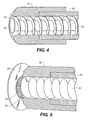
- FIG.4 shows a detail view of yet another embodiment of the invention.
- the rotatable auger 20 terminates in a spreader 65 which rotates with the rotatable auger 20.
- the spreader 65 is a cone-shaped member that spreads the material 10 away from the shaft of the rotatable auger 20 towards the opening 35.
- the single opening 35 is in the form of an annulus and is formed between the spreader 65 on the inside and heat sink 42.
- Heat sink 42 is rigidly attached to the auger enclosure 22.
- the rotation of the spreader 65 within the heat sink 42 sets up a shear in the material, causing agitation and reducing the tendency of the material 10 to compact into an agglomerated solid inside the auger enclosure 22 or the heat sink 42.
- FIG. 5 shows a detail of another embodiment of the invention.
- the openings are provided by a fine screen 75.
- a vibratory actuator 70 imparts vibrational energy to the screen 75 agitating or fluidizing the material 10 in the feeding location 30.
- the direction of the vibration may be co-axial to the rotatable auger 20, perpendicular to the axis of the rotatable auger 20, or both co-axial or perpendicular.
- Fluidized material 10 is forced through the screen 75 by the rotation of the rotatable auger 20. Material 10 passing through the screen 75 then encounters the heated surface 40 which is spaced a short distance from the screen 75. This distance is typically on the order of 50-100 microns, but could be larger or smaller depending on particle size of the material 10 being fed, the size of the openings in the screen 75, and other factors.
Landscapes
- Chemical & Material Sciences (AREA)
- Chemical Kinetics & Catalysis (AREA)
- Engineering & Computer Science (AREA)
- Materials Engineering (AREA)
- Mechanical Engineering (AREA)
- Metallurgy (AREA)
- Organic Chemistry (AREA)
- General Chemical & Material Sciences (AREA)
- Physical Vapour Deposition (AREA)
- Electroluminescent Light Sources (AREA)
- Manufacturing And Processing Devices For Dough (AREA)
Abstract
Description
- The present invention relates to making devices by vaporizing material and more particularly to controllably feeding material to a heated surface.
- An organic light emitting diode (OLED) device includes a substrate, an anode, a hole-transporting layer made of an organic compound, an organic luminescent layer with suitable dopants, an organic electron-transporting layer, and a cathode. OLED devices are attractive because of their low driving voltage, high luminance, wide-angle viewing and capability for full-color flat emission displays. Tang et al. described this multilayer OLED device in their
U.S. Patent Nos. 4,769,292 and4,885,211 . - Physical vapor deposition in a vacuum environment is the principal means of depositing thin organic material films as used in small molecule OLED devices. Such methods are well known, for example Barr in
U.S. Patent No. 2,447,789 andTanabe et al. in EP 0 982 411 . The organic materials used in the manufacture of OLED devices are often subject to degradation when maintained at or near the desired rate dependant vaporization temperature for extended periods of time. Exposure of sensitive organic materials to higher temperatures can cause changes in the structure of the molecules and associated changes in material properties. - DATABASE WPI Week 198130 Derwent Publications Ltd., London, GB; AN 1981-54842D XP002416217 &;
SU 779 441 B (AS BELO METALLOPOLY) 15 November 1980 1980-11-15 - To overcome the thermal sensitivity of these materials, only small quantities of organic materials have been loaded in sources and they are heated as little as possible. In this manner, the material is consumed before it has reached the temperature exposure threshold to cause significant degradation. The limitations with this practice are that the available vaporization rate is very low due to the limitation on heater temperature, and the operation time of the source is very short due to the small quantity of material present in the source. In the prior art, it has been necessary to vent the deposition chamber, disassemble and clean the vapor source, refill the source, reestablish vacuum in the deposition chamber and degas the just-introduced organic material over several hours before resuming operation. The low deposition rate and the frequent and time consuming process associated with recharging a source has placed substantial limitations on the throughput of OLED manufacturing facilities.
- A secondary consequence of heating the entire organic material charge to roughly the same temperature is that it is impractical to mix additional organic materials, such as dopants, with a host material unless the vaporization behavior and vapor pressure of the dopant is very close to that of the host material. This is generally not the case and as a result, prior art devices frequently require the use of separate sources to co-deposit host and dopant materials.
- A consequence of using single component sources is that many sources are required in order to produce films containing a host and multiple dopants. These sources are arrayed one next to the other with the outer sources angled toward the center to approximate a co-deposition condition. In practice, the number of linear sources used to co-deposit different materials has been limited to three. This restriction has imposed a substantial limitation on the architecture of OLED devices, increases the necessary size and cost of the vacuum deposition chamber and decreases the reliability of the system.
- Additionally, the use of separate sources creates a gradient effect in the deposited film where the material in the source closest to the advancing substrate is over represented in the initial film immediately adjacent the substrate while the material in the last source is over represented in the final film surface. This gradient co-deposition is unavoidable in prior art sources where a single material is vaporized from each of multiple sources. The gradient in the deposited film is especially evident when the contribution of either of the end sources is more than a few percent of the central source, such as when a co-host is used.
- A further limitation of prior art sources is that the geometry of the interior of the vapor manifold changes as the organic material charge is consumed. This change requires that the heater temperature change to maintain a constant vaporization rate and it is observed that the overall plume shape of the vapor exiting the orifices can change as a function of the organic material thickness and distribution in the source, particularly when the conductance to vapor flow in the source with a full charge of material is low enough to sustain pressure gradients from non-uniform vaporization within the source. In this case, as the material charge is consumed, the conductance increases and the pressure distribution and hence overall plume shape improve.
- It is therefore an object of the present invention to provide an effective way to vaporize powders.
- This object is achieved in a method for metering powdered or granular material onto or in close proximity to a heated surface to vaporize such material, comprising:
- (a) providing a rotatable auger for receiving powdered or granular material and as the rotatable auger rotates, such rotating rotatable auger translates such powdered or granular material along a feed path to a feeding location at the end of the auger;
- (b) providing a member at the end of the auger which provides agitation or fluidization to the powdered or granular material ;
- (c) providing a heated surface that is in proximity to the feeding location to cause the feeding location to be heated by radiation ;
- (d) providing a thermally conductive path from the feeding location to a heat sink ;
- (e) providing at least one opening in the member such that the pressure produced by the rotating rotatable auger at the feeding location causes the powdered or granular material to be forced through the opening(s) in the member onto the heated surface in a controllable manner, and
- (f) agitating or fluidizing the powdered or granular material in proximity to the feeding location by the member in cooperation with the rotatable auger so as to facilitate the flow of powdered or granular material through the opening(s) in the member to the heated surface where the powdered or granular material is vaporized.
- An advantage of this invention is that it provides controlled delivery of powdered or granular material with reduced expenditures of power. Feed uniformity is substantially improved.
-
-
FIG. 1 is a sectional view of one embodiment of the invention; -
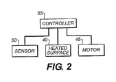
FIG. 2 is a block diagram of a closed-loop control for the invention; -
FIG. 3A and 3B show detail cross-sectional perspectives of an alternative embodiment of the invention; -
FIG. 4 is a detail cross-section perspective of another alternative embodiment of the invention; and -
FIG. 5 is a detail cross-sectional perspective of still another alternative embodiment of the invention. - Turning now to
FIG. 1 , anapparatus 5 for metering powdered orgranular material 10 such as organic material into a heatedsurface 40 is shown. Theapparatus 5 is includes acontainer 15 which holdsmaterial 10.Material 10 can have one or more components and can be powdered or granular. Arotatable auger 20 is disposed in anauger enclosure 22 which in turn is disposed in a material receiving relationship with thecontainer 15. Theauger enclosure 22 has openings 24 for receivingmaterial 10 from thecontainer 5. Therotatable auger 20 movesmaterial 10 along a feed path to afeeding location 30. Rotation of therotatable auger 20 causes thematerial 10 to be subject to pressure at thefeeding location 30. This pressure forces thematerial 10 through one ormore openings 35 formed in amember 36. Member, 36 can be attached to therotatable auger 20 so that themember 36 rotates with therotatable auger 20, and carriesmaterial 10 into contact with a heatedsurface 40 where thematerial 10 is flash evaporated. The rotation ofmember 36 provides agitation or fluidization ofmaterial 10 in the proximity to theopenings 35, reducing the tendency of thematerial 10 to compact into an agglomerated solid inside theauger enclosure 22 orheat sink 42 that would restrict material flow. The proximity of thefeeding location 30 to the heatedsurface 40 can cause the feeding location to be heated by radiation and theauger enclosure 22 by conduction from thefeeding location 30. It can be desirable to coat thefeeding location 30 and theopenings 35 inmember 36 with a thermally insulating layer such as anodization or a thin layer of glass or mica. Additionally, thefeeding location 30 can be made of a material of high thermal conductivity and provided with a thermally conductive path to aheat sink 42. Theheat sink 42 can be a passive device that depends on radiation or convection to a fluid, or it can be an active cooling device such as a Peltier effect chiller. Insulating thefeeding location 30 can reduce condensation of vaporized material in thefeeding location 30, especially around theopenings 35. Providing a conductive path toheat sink 42, reduces thermal exposure ofmaterial 10, and thereby improves material lifetime within theauger enclosure 22. - The
apparatus 5 can operate in a closed-loop control mode, in which case asensor 50 is utilized to measure the vaporization rate of the material 10 as it is evaporated at theheated surface 40. Thesensor 50 can also be used in measuring the material vaporization rate on a substrate either directly or indirectly. For example, a laser can be directed through the plume of evaporated material to directly measure the local concentration of vaporized material. Alternatively, crystal rate monitors indirectly measure the vaporization rate by measuring the rate of deposition of the vaporized material on the crystal surface. These two approaches represent only two of the many well-known methods for sensing the vaporization rate. - Turning now to
FIG. 2 , theapparatus 5 can be operated under closed-loop control which is represented by block diagram. In a close-loop control system, thesensor 50 provides data to acontroller 55, which in turn determines the rate of revolution of a motor 45. The closed loop control can take many forms. In a particularly preferred embodiment, thecontroller 55 is a programmable digital logic device, such as a microcontroller, that reads the input of thesensor 50, which can be either analog input or direct digital input. Thecontroller 55 is operated by an algorithm that utilizes the sensor input as well as internal or externally derived information about the motor 45 rotational speed and the temperature of theheated surface 40 to determine a new commanded speed for therotatable auger 20 and a new commanded temperature for theheated surface 40. There are many known classes of algorithm, such as proportional integral differential control, proportional control, differential control, that can be adapted for use suited to control theapparatus 5. The control strategy can employ feedback as well as feedforward. Alternatively, the control circuit can be implemented as an analog control device, which can implement many of the same classes of algorithm as the digital device. -
FIGS. 3A and 3B show different perspectives of the detail of an alternative embodiment. The portion of the embodiment not shown are essentially the same as those ofFIG. 1 . This embodiment differs in how thematerial 10 at the end of therotatable auger 20 is fluidized or agitated. Aclockwork spring 60 is attached to therotatable auger 20 so that it rotates with therotatable auger 20, agitating orfluidized material 10 in the vicinity of themember 36 containing theopenings 35. Themember 36 maybe rigidly affixed to theauger enclosure 22 or may instead be constrained to rotate with therotatable auger 20. By maintaining an agitated or fluidized region ofmaterial 10 in the immediate proximity of themember 36, the tendency of the material 10 to compact into an agglomerated solid inside theauger enclosure 22 is reduced. -
FIG.4 shows a detail view of yet another embodiment of the invention. In this embodiment, therotatable auger 20 terminates in aspreader 65 which rotates with therotatable auger 20. Thespreader 65 is a cone-shaped member that spreads thematerial 10 away from the shaft of therotatable auger 20 towards theopening 35. Thesingle opening 35 is in the form of an annulus and is formed between thespreader 65 on the inside andheat sink 42.Heat sink 42, is rigidly attached to theauger enclosure 22. The rotation of thespreader 65 within theheat sink 42, sets up a shear in the material, causing agitation and reducing the tendency of the material 10 to compact into an agglomerated solid inside theauger enclosure 22 or theheat sink 42. -
FIG. 5 shows a detail of another embodiment of the invention. In this embodiment, the openings are provided by afine screen 75. Avibratory actuator 70 imparts vibrational energy to thescreen 75 agitating or fluidizing the material 10 in the feedinglocation 30. The direction of the vibration may be co-axial to therotatable auger 20, perpendicular to the axis of therotatable auger 20, or both co-axial or perpendicular. Fluidizedmaterial 10 is forced through thescreen 75 by the rotation of therotatable auger 20.Material 10 passing through thescreen 75 then encounters theheated surface 40 which is spaced a short distance from thescreen 75. This distance is typically on the order of 50-100 microns, but could be larger or smaller depending on particle size of the material 10 being fed, the size of the openings in thescreen 75, and other factors. - It is understood by those of ordinary skill in the art that although the invention is motivated by the need to reduce the time organic materials spend at elevated temperature and is described in the context of vaporization of organic materials, the invention is suitable for vaporization of any powdered or granular material.
-
- 5
- Apparatus
- 10
- Organic material
- 15
- Container
- 20
- Rotatable auger
- 22
- Auger enclosure
- 24
- Auger enclosure opening
- 30
- Feeding location
- 35
- Opening
- 36
- Member
- 40
- Heated surface
- 42
- Heat sink
- 45
- Motor
- 50
- Sensor
- 55
- Controller
- 60
- Clockwork spring
- 65
- Spreader
- 70
- Vibratory actuator
- 75
- Screen
Claims (7)
- A method for metering powdered or granular material (10) to vaporize such material, comprising:(a) providing a rotatable auger (20) for receiving the powdered or granular material (10) and as the rotatable auger (20) rotates, such rotating rotatable auger (20) translates such powdered or granular material (10) along a feed path to a feeding location (30) at the end of the auger (20);(b) providing a member (36) at the end of the auger (20) which provides agitation or fluidization to the powdered or granular material (10);(c) providing a heated surface (40) that is in proximity to the feeding location (30) to cause the feeding location to be heated by radiation;(d) providing a thermally conductive path from the feeding location (30) to a heat sink (42);(e) providing at least one opening (35) in the member (36) such that the pressure produced by the rotating rotatable auger at the feeding location (30) causes the powdered or granular material (10) to be forced through the opening(s) (35) in the member (36) onto the heated surface (40) in a controllable manner; and(f) agitating or fluidizing the powdered or granular material (10) in proximity to the feeding location (30) by the member (36) in cooperation with the rotatable auger (20) so as to facilitate the flow of powdered or granular material (10) through the opening(s) (35) in the member (36) to the heated surface (40) where the powdered or granular material (10) is flash evaporated.
- The method of claim 1, wherein agitating or fluidizing the powdered or granular material (10) is achieved by providing the opening(s) (35) at the feeding location (30) within one or more moving surfaces.
- The method of claim 1, wherein the member (36) is a rotating agitator moving in cooperation with the rotatable auger (20).
- The method of claim 1, wherein agitating or fluidizing the powdered or granular material (10) is provided by introducing vibrational energy into the opening(s) (35).
- The method of claim 1, wherein the powdered or granular material (10) is an organic material and is vaporized in order to deposit a thin film organic layer on an OLED surface.
- The method of claim 1, further including controlling the speed of rotation of the rotatable auger (20) and the temperature of the heated surface (40) as a function of the vaporization rate.
- The method of claim 1, further including controlling the rate of delivery of powdered or granular material (10) through the opening(s) (35).
Applications Claiming Priority (2)
| Application Number | Priority Date | Filing Date | Title |
|---|---|---|---|
| US11/121,242 US7625602B2 (en) | 2005-05-03 | 2005-05-03 | Controllably feeding powdered or granular material |
| PCT/US2006/015351 WO2006118837A2 (en) | 2005-05-03 | 2006-04-25 | Method for feeding powdered or granular material |
Publications (2)
| Publication Number | Publication Date |
|---|---|
| EP1893785A2 EP1893785A2 (en) | 2008-03-05 |
| EP1893785B1 true EP1893785B1 (en) | 2012-07-11 |
Family
ID=37103274
Family Applications (1)
| Application Number | Title | Priority Date | Filing Date |
|---|---|---|---|
| EP06751155A Active EP1893785B1 (en) | 2005-05-03 | 2006-04-25 | Method for feeding powdered or granular material |
Country Status (4)
| Country | Link |
|---|---|
| US (1) | US7625602B2 (en) |
| EP (1) | EP1893785B1 (en) |
| JP (1) | JP5237088B2 (en) |
| WO (1) | WO2006118837A2 (en) |
Families Citing this family (9)
| Publication number | Priority date | Publication date | Assignee | Title |
|---|---|---|---|---|
| JP5179739B2 (en) * | 2006-09-27 | 2013-04-10 | 東京エレクトロン株式会社 | Vapor deposition apparatus, vapor deposition apparatus control apparatus, vapor deposition apparatus control method, and vapor deposition apparatus usage method |
| US7883583B2 (en) * | 2008-01-08 | 2011-02-08 | Global Oled Technology Llc | Vaporization apparatus with precise powder metering |
| US8048230B2 (en) * | 2008-11-14 | 2011-11-01 | Global Oled Technology Llc | Metering and vaporizing particulate material |
| US8062427B2 (en) * | 2008-11-14 | 2011-11-22 | Global Oled Technology Llc | Particulate material metering and vaporization |
| US7972443B2 (en) * | 2008-11-14 | 2011-07-05 | Global Oled Technology Llc | Metering of particulate material and vaporization thereof |
| JP4974036B2 (en) | 2009-11-19 | 2012-07-11 | 株式会社ジャパンディスプレイセントラル | Manufacturing method of organic EL device |
| CN106119781B (en) | 2016-07-27 | 2018-10-30 | 京东方科技集团股份有限公司 | Vaporising device, evaporated device and evaporation coating method |
| CN117355364A (en) | 2021-05-21 | 2024-01-05 | 默克专利有限公司 | Method for continuously purifying at least one functional material and device for continuously purifying at least one functional material |
| CN115595550B (en) * | 2022-10-24 | 2024-07-23 | 广东振华科技股份有限公司 | Automatic material-changing continuous evaporation coating device and method for AF (automatic film) granular film material |
Family Cites Families (16)
| Publication number | Priority date | Publication date | Assignee | Title |
|---|---|---|---|---|
| US2447789A (en) * | 1945-03-23 | 1948-08-24 | Polaroid Corp | Evaporating crucible for coating apparatus |
| JPS50109182A (en) * | 1974-02-07 | 1975-08-28 | ||
| SU779441A1 (en) | 1978-07-31 | 1980-11-15 | Институт Механики Металлополимерных Систем Ан Белорусской Сср | Dosing feeder |
| DE3530106A1 (en) * | 1985-08-23 | 1987-02-26 | Kempten Elektroschmelz Gmbh | VAPORIZATION MATERIAL FOR VAPORIZING INORGANIC COMPOUNDS BY MEANS OF A PHOTON-GENERATING RADIATION HEATING SOURCE IN CONTINUOUSLY OPERATED VACUUM VACUUM DEVICES |
| US4885211A (en) * | 1987-02-11 | 1989-12-05 | Eastman Kodak Company | Electroluminescent device with improved cathode |
| US4769292A (en) * | 1987-03-02 | 1988-09-06 | Eastman Kodak Company | Electroluminescent device with modified thin film luminescent zone |
| JPH0645213Y2 (en) * | 1988-02-08 | 1994-11-16 | 住友電気工業株式会社 | High precision powder feeder |
| EP0585848A1 (en) * | 1992-09-02 | 1994-03-09 | Hoechst Aktiengesellschaft | Method and apparatus for thin film formation by CVD |
| JP2000248358A (en) * | 1999-03-01 | 2000-09-12 | Casio Comput Co Ltd | Vapor deposition device and vapor deposition method |
| IT1310745B1 (en) | 1999-11-26 | 2002-02-22 | Lawer Spa | DEVICE FOR DOSED DISPENSING OF SLIDING PRODUCTS. |
| JP2003293121A (en) * | 2002-04-05 | 2003-10-15 | Cluster Ion Beam Technology Kk | Vapor deposition crucible having means for supplying vapor deposition material |
| US7118783B2 (en) * | 2002-06-26 | 2006-10-10 | Micron Technology, Inc. | Methods and apparatus for vapor processing of micro-device workpieces |
| US6837939B1 (en) * | 2003-07-22 | 2005-01-04 | Eastman Kodak Company | Thermal physical vapor deposition source using pellets of organic material for making OLED displays |
| US7339139B2 (en) * | 2003-10-03 | 2008-03-04 | Darly Custom Technology, Inc. | Multi-layered radiant thermal evaporator and method of use |
| US7288285B2 (en) * | 2004-09-21 | 2007-10-30 | Eastman Kodak Company | Delivering organic powder to a vaporization zone |
| US7213347B2 (en) | 2005-05-03 | 2007-05-08 | Eastman Kodak Company | Metering material to promote rapid vaporization |
-
2005
- 2005-05-03 US US11/121,242 patent/US7625602B2/en active Active
-
2006
- 2006-04-25 JP JP2008510033A patent/JP5237088B2/en active Active
- 2006-04-25 EP EP06751155A patent/EP1893785B1/en active Active
- 2006-04-25 WO PCT/US2006/015351 patent/WO2006118837A2/en active Application Filing
Also Published As
| Publication number | Publication date |
|---|---|
| EP1893785A2 (en) | 2008-03-05 |
| US7625602B2 (en) | 2009-12-01 |
| JP2008540829A (en) | 2008-11-20 |
| WO2006118837A2 (en) | 2006-11-09 |
| WO2006118837A3 (en) | 2007-04-05 |
| US20060251811A1 (en) | 2006-11-09 |
| JP5237088B2 (en) | 2013-07-17 |
Similar Documents
| Publication | Publication Date | Title |
|---|---|---|
| US7625601B2 (en) | Controllably feeding organic material in making OLEDs | |
| EP1893785B1 (en) | Method for feeding powdered or granular material | |
| US7165340B2 (en) | Feeding organic material to a heated surface | |
| JP4886694B2 (en) | Supply of particulate material to the vaporization zone | |
| JP5480332B2 (en) | Supply of particulate material to the vaporization zone | |
| US7288285B2 (en) | Delivering organic powder to a vaporization zone | |
| US7288286B2 (en) | Delivering organic powder to a vaporization zone | |
| US20110033973A1 (en) | Deposition apparatus for temperature sensitive materials | |
| US7993459B2 (en) | Delivering particulate material to a vaporization zone | |
| EP1877596B1 (en) | Metering material to promote rapid vaporization | |
| US7398605B2 (en) | Method of feeding particulate material to a heated vaporization surface | |
| JP2012518092A (en) | Simple powder supply and vaporizer |
Legal Events
| Date | Code | Title | Description |
|---|---|---|---|
| PUAI | Public reference made under article 153(3) epc to a published international application that has entered the european phase |
Free format text: ORIGINAL CODE: 0009012 |
|
| 17P | Request for examination filed |
Effective date: 20071025 |
|
| AK | Designated contracting states |
Kind code of ref document: A2 Designated state(s): DE GB NL |
|
| DAX | Request for extension of the european patent (deleted) | ||
| RBV | Designated contracting states (corrected) |
Designated state(s): DE GB NL |
|
| 17Q | First examination report despatched |
Effective date: 20090128 |
|
| RAP1 | Party data changed (applicant data changed or rights of an application transferred) |
Owner name: GLOBAL OLED TECHNOLOGY LLC |
|
| RAP1 | Party data changed (applicant data changed or rights of an application transferred) |
Owner name: GLOBAL OLED TECHNOLOGY LLC |
|
| GRAP | Despatch of communication of intention to grant a patent |
Free format text: ORIGINAL CODE: EPIDOSNIGR1 |
|
| RIN1 | Information on inventor provided before grant (corrected) |
Inventor name: KOPPE, BRUCE EDWARD Inventor name: REDDEN, NEIL PETER Inventor name: LONG, MICHAEL Inventor name: PALONE, THOMAS WILLIAM |
|
| GRAS | Grant fee paid |
Free format text: ORIGINAL CODE: EPIDOSNIGR3 |
|
| GRAA | (expected) grant |
Free format text: ORIGINAL CODE: 0009210 |
|
| AK | Designated contracting states |
Kind code of ref document: B1 Designated state(s): DE GB NL |
|
| REG | Reference to a national code |
Ref country code: GB Ref legal event code: FG4D |
|
| REG | Reference to a national code |
Ref country code: DE Ref legal event code: R096 Ref document number: 602006030710 Country of ref document: DE Effective date: 20120906 |
|
| REG | Reference to a national code |
Ref country code: NL Ref legal event code: T3 |
|
| PLBE | No opposition filed within time limit |
Free format text: ORIGINAL CODE: 0009261 |
|
| STAA | Information on the status of an ep patent application or granted ep patent |
Free format text: STATUS: NO OPPOSITION FILED WITHIN TIME LIMIT |
|
| 26N | No opposition filed |
Effective date: 20130412 |
|
| REG | Reference to a national code |
Ref country code: DE Ref legal event code: R097 Ref document number: 602006030710 Country of ref document: DE Effective date: 20130412 |
|
| PGFP | Annual fee paid to national office [announced via postgrant information from national office to epo] |
Ref country code: NL Payment date: 20240418 Year of fee payment: 19 |
|
| PGFP | Annual fee paid to national office [announced via postgrant information from national office to epo] |
Ref country code: GB Payment date: 20240418 Year of fee payment: 19 |
|
| PGFP | Annual fee paid to national office [announced via postgrant information from national office to epo] |
Ref country code: DE Payment date: 20240418 Year of fee payment: 19 |