EP1893307B1 - Fire suppression system using high velocity low pressure emitters - Google Patents
Fire suppression system using high velocity low pressure emitters Download PDFInfo
- Publication number
- EP1893307B1 EP1893307B1 EP06773058.0A EP06773058A EP1893307B1 EP 1893307 B1 EP1893307 B1 EP 1893307B1 EP 06773058 A EP06773058 A EP 06773058A EP 1893307 B1 EP1893307 B1 EP 1893307B1
- Authority
- EP
- European Patent Office
- Prior art keywords
- gas
- nozzle
- emitter
- liquid
- outlet
- Prior art date
- Legal status (The legal status is an assumption and is not a legal conclusion. Google has not performed a legal analysis and makes no representation as to the accuracy of the status listed.)
- Expired - Lifetime
Links
Images


Classifications
-
- A—HUMAN NECESSITIES
- A62—LIFE-SAVING; FIRE-FIGHTING
- A62C—FIRE-FIGHTING
- A62C31/00—Delivery of fire-extinguishing material
- A62C31/005—Delivery of fire-extinguishing material using nozzles
-
- A—HUMAN NECESSITIES
- A62—LIFE-SAVING; FIRE-FIGHTING
- A62C—FIRE-FIGHTING
- A62C37/00—Control of fire-fighting equipment
- A62C37/08—Control of fire-fighting equipment comprising an outlet device containing a sensor, or itself being the sensor, i.e. self-contained sprinklers
-
- A—HUMAN NECESSITIES
- A62—LIFE-SAVING; FIRE-FIGHTING
- A62C—FIRE-FIGHTING
- A62C31/00—Delivery of fire-extinguishing material
-
- A—HUMAN NECESSITIES
- A62—LIFE-SAVING; FIRE-FIGHTING
- A62C—FIRE-FIGHTING
- A62C31/00—Delivery of fire-extinguishing material
- A62C31/02—Nozzles specially adapted for fire-extinguishing
-
- A—HUMAN NECESSITIES
- A62—LIFE-SAVING; FIRE-FIGHTING
- A62C—FIRE-FIGHTING
- A62C35/00—Permanently-installed equipment
- A62C35/58—Pipe-line systems
-
- A—HUMAN NECESSITIES
- A62—LIFE-SAVING; FIRE-FIGHTING
- A62C—FIRE-FIGHTING
- A62C35/00—Permanently-installed equipment
- A62C35/58—Pipe-line systems
- A62C35/60—Pipe-line systems wet, i.e. containing extinguishing material even when not in use
-
- A—HUMAN NECESSITIES
- A62—LIFE-SAVING; FIRE-FIGHTING
- A62C—FIRE-FIGHTING
- A62C35/00—Permanently-installed equipment
- A62C35/58—Pipe-line systems
- A62C35/64—Pipe-line systems pressurised
-
- A—HUMAN NECESSITIES
- A62—LIFE-SAVING; FIRE-FIGHTING
- A62C—FIRE-FIGHTING
- A62C35/00—Permanently-installed equipment
- A62C35/58—Pipe-line systems
- A62C35/68—Details, e.g. of pipes or valve systems
-
- A—HUMAN NECESSITIES
- A62—LIFE-SAVING; FIRE-FIGHTING
- A62C—FIRE-FIGHTING
- A62C37/00—Control of fire-fighting equipment
- A62C37/08—Control of fire-fighting equipment comprising an outlet device containing a sensor, or itself being the sensor, i.e. self-contained sprinklers
- A62C37/10—Releasing means, e.g. electrically released
-
- A—HUMAN NECESSITIES
- A62—LIFE-SAVING; FIRE-FIGHTING
- A62C—FIRE-FIGHTING
- A62C99/00—Subject matter not provided for in other groups of this subclass
- A62C99/0009—Methods of extinguishing or preventing the spread of fire by cooling down or suffocating the flames
- A62C99/0072—Methods of extinguishing or preventing the spread of fire by cooling down or suffocating the flames using sprayed or atomised water
-
- B—PERFORMING OPERATIONS; TRANSPORTING
- B05—SPRAYING OR ATOMISING IN GENERAL; APPLYING FLUENT MATERIALS TO SURFACES, IN GENERAL
- B05B—SPRAYING APPARATUS; ATOMISING APPARATUS; NOZZLES
- B05B1/00—Nozzles, spray heads or other outlets, with or without auxiliary devices such as valves, heating means
- B05B1/26—Nozzles, spray heads or other outlets, with or without auxiliary devices such as valves, heating means with means for mechanically breaking-up or deflecting the jet after discharge, e.g. with fixed deflectors; Breaking-up the discharged liquid or other fluent material by impinging jets
- B05B1/262—Nozzles, spray heads or other outlets, with or without auxiliary devices such as valves, heating means with means for mechanically breaking-up or deflecting the jet after discharge, e.g. with fixed deflectors; Breaking-up the discharged liquid or other fluent material by impinging jets with fixed deflectors
- B05B1/265—Nozzles, spray heads or other outlets, with or without auxiliary devices such as valves, heating means with means for mechanically breaking-up or deflecting the jet after discharge, e.g. with fixed deflectors; Breaking-up the discharged liquid or other fluent material by impinging jets with fixed deflectors the liquid or other fluent material being symmetrically deflected about the axis of the nozzle
-
- B—PERFORMING OPERATIONS; TRANSPORTING
- B05—SPRAYING OR ATOMISING IN GENERAL; APPLYING FLUENT MATERIALS TO SURFACES, IN GENERAL
- B05B—SPRAYING APPARATUS; ATOMISING APPARATUS; NOZZLES
- B05B7/00—Spraying apparatus for discharge of liquids or other fluent materials from two or more sources, e.g. of liquid and air, of powder and gas
- B05B7/02—Spray pistols; Apparatus for discharge
- B05B7/08—Spray pistols; Apparatus for discharge with separate outlet orifices, e.g. to form parallel jets, i.e. the axis of the jets being parallel, to form intersecting jets, i.e. the axis of the jets converging but not necessarily intersecting at a point
-
- B—PERFORMING OPERATIONS; TRANSPORTING
- B05—SPRAYING OR ATOMISING IN GENERAL; APPLYING FLUENT MATERIALS TO SURFACES, IN GENERAL
- B05B—SPRAYING APPARATUS; ATOMISING APPARATUS; NOZZLES
- B05B7/00—Spraying apparatus for discharge of liquids or other fluent materials from two or more sources, e.g. of liquid and air, of powder and gas
- B05B7/02—Spray pistols; Apparatus for discharge
- B05B7/08—Spray pistols; Apparatus for discharge with separate outlet orifices, e.g. to form parallel jets, i.e. the axis of the jets being parallel, to form intersecting jets, i.e. the axis of the jets converging but not necessarily intersecting at a point
- B05B7/0807—Spray pistols; Apparatus for discharge with separate outlet orifices, e.g. to form parallel jets, i.e. the axis of the jets being parallel, to form intersecting jets, i.e. the axis of the jets converging but not necessarily intersecting at a point to form intersecting jets
- B05B7/0853—Spray pistols; Apparatus for discharge with separate outlet orifices, e.g. to form parallel jets, i.e. the axis of the jets being parallel, to form intersecting jets, i.e. the axis of the jets converging but not necessarily intersecting at a point to form intersecting jets with one single gas jet and several jets constituted by a liquid or a mixture containing a liquid
-
- B—PERFORMING OPERATIONS; TRANSPORTING
- B05—SPRAYING OR ATOMISING IN GENERAL; APPLYING FLUENT MATERIALS TO SURFACES, IN GENERAL
- B05B—SPRAYING APPARATUS; ATOMISING APPARATUS; NOZZLES
- B05B7/00—Spraying apparatus for discharge of liquids or other fluent materials from two or more sources, e.g. of liquid and air, of powder and gas
- B05B7/02—Spray pistols; Apparatus for discharge
- B05B7/08—Spray pistols; Apparatus for discharge with separate outlet orifices, e.g. to form parallel jets, i.e. the axis of the jets being parallel, to form intersecting jets, i.e. the axis of the jets converging but not necessarily intersecting at a point
- B05B7/0892—Spray pistols; Apparatus for discharge with separate outlet orifices, e.g. to form parallel jets, i.e. the axis of the jets being parallel, to form intersecting jets, i.e. the axis of the jets converging but not necessarily intersecting at a point the outlet orifices for jets constituted by a liquid or a mixture containing a liquid being disposed on a circle
Definitions
- This invention concerns fire suppression systems using devices for emitting atomized liquid, the device injecting the liquid into a gas flow stream where the liquid is atomized and projected away from the device onto a fire.
- Fire control and suppression sprinkler systems generally include a plurality of individual sprinkler heads which are usually ceiling mounted about the area to be protected.
- the sprinkler heads are normally maintained in a closed condition and include a thermally responsive sensing member to determine when a fire condition has occurred.
- the thermally responsive member Upon actuation of the thermally responsive member, the sprinkler head is opened, permitting pressurized water at each of the individual sprinkler heads to freely flow therethrough for extinguishing the fire.
- the individual sprinkler heads are spaced apart from each other by distances determined by the type of protection they are intended to provide (e.g., light or ordinary hazard conditions) and the ratings of the individual sprinklers, as determined by industry accepted rating agencies such as Underwriters Laboratories, Inc., Factory Mutual Research Corp. and/or the National Fire Protection Association.
- the piping that connects the sprinkler heads to the water source is, in many instances, at all times filled with water. This is known as a wet system, with the water being immediately available at the sprinkler head upon its thermal actuation.
- a wet system with the water being immediately available at the sprinkler head upon its thermal actuation.
- the sprinkler system is installed in an unheated area, such as warehouses. In those situations, if a wet system is used, and in particular, since the water is not flowing within the piping system over long periods of time, there is a danger of the water within the pipes freezing.
- the water spray When actuated, traditional sprinkler heads release a spray of fire suppressing liquid, such as water, onto the area of the fire.
- the water spray while somewhat effective, has several disadvantages.
- the water droplets comprising the spray are relatively large and will cause water damage to the furnishings or goods in the burning region.
- the water spray also exhibits limited modes of fire suppression.
- the spray being composed of relatively large droplets providing a small total surface area, does not efficiently absorb heat and therefore cannot operate efficiently to prevent spread of the fire by lowering the temperature of the ambient air around the fire. Large droplets also do not block radiative heat transfer effectively, thereby allowing the fire to spread by this mode.
- the spray furthermore does not efficiently displace oxygen from the ambient air around the fire, nor is there usually sufficient downward momentum of the droplets to overcome the smoke plume and attack the base of the fire.
- Resonance tubes use acoustic energy, generated by an oscillatory pressure wave interaction between a gas jet and a cavity, to atomize a liquid that is injected into the region near the resonance tube where the acoustic energy is present.
- resonance tubes of known design and operational mode generally do not have the fluid flow characteristics required to be effective in fire protection applications.
- the volume of flow from the resonance tube tends to be inadequate, and the water particles generated by the atomization process have relatively low velocities.
- these water particles are decelerated significantly within about 8 to 16 inches of the sprinkler head and cannot overcome the plume of rising combustion gas generated by a fire.
- the water particles cannot get to the fire source for effective fire suppression.
- the water particle size generated by the atomization is ineffective at reducing the oxygen content to suppress a fire if the ambient temperature is below 55[deg.]C.
- known resonance tubes require relatively large gas volumes delivered at high pressure.
- US 6390203 discloses a fire suppression system according to the preamble of claim 1.
- US3084874 discloses an emitter wherein multiple shock front/waves are formed.
- WO00/41769 , WO03/030995 and US2004188104 refer to fire suppression systems according to the preamble of claim 1.
- the invention concerns a fire suppression system according to claim 1.
- the system comprises a source of pressurized gas, a source of pressurized liquid and at least one emitter for atomizing and discharging the liquid entrained in the gas on a fire.
- a gas conduit provides fluid communication between the pressurized gas source and the emitter, and a piping network provides fluid communication between the pressurized liquid source and the emitter.
- a first valve in the gas conduit controls pressure and flow rate of the gas to the emitter, and a second valve in the piping network controls pressure and flow rate of the liquid to the emitter.
- a pressure transducer measures pressure within the gas conduit.
- a fire detection device is positioned proximate to the emitter.
- a control system is in communication with the- first and second valves, the pressure transducer and the fire detection device.
- the control system receives signals from the pressure transducer and the fire detection device and opens the valves in response to a signal indicative of a fire from the fire detection device.
- the control system actuates the first valve so as to maintain a predetermined pressure within the gas conduit for operation of the emitter.
- the system may also include a plurality of compressed gas tanks forming the source of pressurized gas and a high pressure manifold that provides fluid communication between the compressed gas tanks and the first valve.
- a plurality of control valves each one being associated with one of the compressed gas tanks.
- a supervisory loop in communication with the control system and the control valves monitors the open and closed status of the control valves.
- the invention also encompasses a method of operating a fire suppression system according to claim 7.
- the system has an emitter comprising a nozzle according to the characterizing part of claim 1.
- the method comprising: discharging the liquid from the orifice; discharging the gas from the outlet; establishing a first shock front between the outlet and the deflector surface; establishing a second shock front proximate to the deflector surface; entraining the liquid in the gas to form a liquid- gas stream; and projecting the liquid-gas stream from the emitter.
- the method also includes using a plurality of compressed gas tanks as the source of pressurized gas.
- a plurality of control valves each one being associated with one of the compressed gas tanks, is used in conjunction with a supervisory loop in communication with the control valves for monitoring the open and closed status of the control valves.
- the method further comprises monitoring the status of the control valves and maintaining the control valves in an open configuration during operation of the system.
- Figure 1 is a schematic diagram illustrating an exemplary fire suppression system according to the invention
- Figure 2 is a longitudinal sectional view of a high velocity low pressure emitter used in the fire suppression system shown in Figure 1 ;
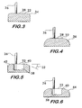
- Figure 3 is a longitudinal sectional view showing a component of the emitter depicted in Figure 2 ;
- Figure 4 is a longitudinal sectional view showing a component of the emitter depicted in Figure 2 ;
- Figure 5 is a longitudinal sectional view showing a component of the emitter depicted in Figure 2 ;
- Figure 6 is a longitudinal sectional view showing a component of the emitter depicted in Figure 2 ;
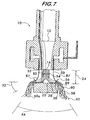
- Figure 7 is a diagram depicting fluid flow from the emitter based upon a Schlieren photograph of the emitter shown in Figure 2 in operation.
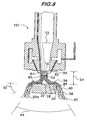
- Figure 8 is a diagram depicting predicted fluid flow for another embodiment of the emitter.
- System 11 includes a plurality of high velocity low pressure emitters 10, described in detail below. Emitters 10 are arranged in a potential fire hazard zone 13, the system comprising one or more such zones, each zone having its own bank of emitters. For clarity, only one zone is described herein, it being understood that the description is applicable to additional fire hazard zones as shown.
- the emitters 10 are connected via a piping network 15 to a source of pressurized water 17.
- a water control valve 19 controls the flow of water from the source 17 to the emitters 10.
- the emitters are also in fluid communication with a source of pressurized gas 21 through a gas conduit network 23.
- the pressurized gas is preferably an inert gas such as nitrogen, and is maintained in banks of highpressure cylinders 25. Cylinders 25 may be pressurized up to 17.24 MPa (2,500 psig). For large systems which require large volumes of gas, one or more lower pressure tanks (about 2.41 MPa (350 psig)) having volumes on the order of 113.55 m 3 (30,000 gallons) may be used.
- Valves 27 of cylinders 25 are preferably- maintained in an open state in communication with a high pressure manifold 29. Gas flow rate and pressure from the manifold to the gas conduit 23 are controlled by a high pressure gas control valve 31. Pressure in the conduit 23 downstream of the high pressure control valve 31 is monitored by a pressure transducer 33. Flow of gas to the emitters 10 in each fire hazard zone 13 is further controlled by a low pressure valve 35 downstream of the pressure transducer.
- Each fire hazard zone 13 is monitored by one or more fire detection devices 37. These detection devices operate in any of the various known modes for fire detection, such as sensing of flame, heat, rate of temperature rise, smoke detection or combinations thereof.
- the system components thus described are coordinated and controlled by a control system 39, which comprises a microprocessor 41 having a control panel display (not shown), resident software, and a programmable logic controller 43.
- the control system communicates with the system components to receive information and issue control commands as follows.
- Each cylinder valve 27 is monitored as to its status (open or closed) by a supervisory loop 45 that communicates with the microprocessor 41, which provides a visual indication of the cylinder valve status.
- Water control valve 19 is also in communication with microprocessor 41 via a communication line 47, which allows the valve 19 to be monitored and controlled (opened and closed) by the control system.
- gas control valve 35 communicates with the control system via a communication line 49, and the fire detection devices 37 also communicate with the control system via communication lines 51.
- the pressure transducer 35 provides its signals to the programmable logic controller 43 over communication line 53.
- the programmable logic controller is also in communication with the high pressure gas valve 31 over communication line 55, and with the microprocessor 41 over communication line 57.
- fire detectors 37 sense a fire event and provide a signal to the microprocessor 41 over communication line 51.
- the microprocessor actuates the logic controller 43.
- controller 43 may be a separate controller or an integral part of the high pressure control valve 31.
- the logic controller 43 receives a signal from the pressure transducer 33 via communication line 53 indicative of the pressure in the gas conduit 23.
- the logic controller 43 opens the high pressure gas valve 31 while the microprocessor 41 opens the gas control valve 35 and the water control valve 19 using respective communication lines 49 and 47. Nitrogen from tanks 25 and water from source 17 are thus permitted to flow through gas conduit 23 and water piping network 15 respectively.
- Preferred water pressure for proper operation of the emitters 10 is between about 6.89 kPa (1 psig) and about 344.74kPa (50 psig) as described below.
- the logic controller 43 operates valve 31 to maintain the correct gas pressure (between about 200kPa (29 psia) and about 414 kPa 60 psia)) and flow rate to operate the emitters 10 within the parameters as described below.
- the microprocessor 41 closes the gas and water valves 35 and 19, and the logic controller 43 closes the high pressure control valve 31.
- the control system 39 continues to monitor all the fire hazard zones 13, and in the event of another fire or the re-flashing of the initial fire the above described sequence is repeated.
- FIG. 2 shows a longitudinal sectional view of a high velocity low pressure emitter 10 according to the invention.
- Emitter 10 comprises a convergent nozzle 12 having an inlet 14 and an outlet 16.
- Outlet 16 may range in diameter between about 3.2 mm 1/8 inch) to about 25.4 mm (1 inch) for many applications.
- Inlet 14 is in fluid communication with a pressurized gas supply 18 that provides gas to the nozzle at a predetermined pressure and flow rate.
- nozzle 12 has a curved convergent inner surface 20.
- a deflector surface 22 is positioned in spaced apart relation with the nozzle 12, a gap 24 being established between the deflector surface and the nozzle outlet.
- the gap may range in size between about 2.54 mm (1/10 inches) to about 19.05 mm (3/4 inches).
- the deflector surface 22 is held in spaced relation from the nozzle by one or more support legs 26.
- deflector surface 22 comprises a flat surface portion 28 substantially aligned with the nozzle outlet 16, and an angled surface portion 30 contiguous with and surrounding the flat portion.
- Flat portion 28 is substantially perpendicular to the gas flow from nozzle 12, and has a minimum diameter approximately equal to the diameter of the outlet 16.
- the angled portion 30 is oriented at a sweep back angle 32 from the flat portion. The sweep back angle may range between about 15[deg.] and about 45[deg.] and, along with the size of gap 24, determines the dispersion pattern of the flow from the emitter.
- Deflector surface 22 may have other shapes, such as the curved upper edge 34 shown in Figure 3 and the curved edge 36 shown in Figure 4 . As shown in Figures 5 and 6 , the deflector surface 22 may also include a closed end resonance tube 38 surrounded by a flat portion 40 and a swept back, angled portion 42 ( Figure 5 ) or a curved portion 44 ( Figure 6 ). The diameter and depth of the resonance cavity may be approximately equal to the diameter of outlet 16.
- an annular chamber 46 surrounds nozzle 12.
- Chamber 46 is in fluid communication with a pressurized liquid supply 48 that provides a liquid to the chamber at a predetermined pressure and flow rate.
- a plurality of ducts 50 extend from the chamber 46.
- Each duct has an exit orifice 52 positioned adjacent to nozzle outlet 16.
- the exit orifices have a diameter of about 0.79 mm (1/32 inch) to about 3.2 mm (1/8 inch).
- Preferred distances between the nozzle outlet 16 and the exit orifices 52 range between about 0.4 mm (1/64 inch) to about 3.2 mm (1/8 inch) as measured along a radius line from the edge of the nozzle outlet to the closest edge of the exit orifice.
- Liquid for example, water for fire suppression, flows from the pressurized supply 48 into the chamber 46 and through the ducts 50, exiting from each orifice 52 where it is atomized by the gas flow from the pressurized gas supply that flows through the nozzle 12 and exits through the nozzle outlet 16 as described in detail below.
- Emitter 10 when configured for use in a fire suppression system, is designed to operate with a preferred gas pressure between about 200 kPa (29 psia) to about 414 kPa (60 psia) at the nozzle inlet 14 and a preferred water pressure between about 6.89 kPa (1 psig) and about 345 kPa (50 psig) in chamber 46.
- Feasible gases include nitrogen, other inert gases, mixtures of inert gases as well as mixtures of inert and chemically active gases such as air. Operation of the emitter 10 is described with reference to Figure 7 which is a drawing based upon Schlieren photographic analysis of an operating emitter.
- Gas 85 exits the nozzle outlet 16 at about Mach 1.5 and impinges on the deflector surface 22. Simultaneously, water 87 is discharged from exit orifices 52.
- a shock front is a region of flow transition from supersonic to subsonic velocity. Water 87 exiting the orifices 52 does not enter the region of the first shock front 54.
- a second shock front 56 forms proximate to the deflector surface at the border between the flat surface portion 28 and the angled surface portion 30.
- Water 87 discharged from the orifices 52 is entrained with the gas jet 85 proximate to the second shock front 56 forming a liquid-gas stream 60.
- One method of entrainment is to use the pressure differential between the pressure in the gas flow jet and the ambient.
- Shock diamonds 58 form in a region along the angled portion 30, the shock diamonds being confined within the liquid-gas stream 60, which projects outwardly and downwardly from the emitter.
- the shock diamonds are also transition regions between super and subsonic flow velocity and are the result of the gas flow being overexpanded as it exits the nozzle.
- Overexpanded flow describes a flow regime wherein the external pressure (i.e., the ambient atmospheric pressure in this case) is higher than the gas exit pressure at the nozzle.
- the emitter 10 operates with multiple mechanisms of atomization which produce water particles 62 less than 20 ⁇ m in diameter, the majority of the particles being measured at less than 5 ⁇ m.
- the smaller droplets are buoyant in air. This characteristic allows them to maintain proximity to the fire source for greater fire suppression effect.
- the particles maintain significant downward momentum, allowing the liquid-gas stream 60 to overcome the rising plume of combustion gases resulting from a fire. Measurements show the liquid-gas stream having a velocity of 6.1 m/s (1,200 ft/min 0.48 m (18 inches) from the emitter, and a velocity of 3.56 m/s (700 ft/min) 2.44 m (8 feet) from the emitter.
- the flow from the emitter is observed to impinge on the floor of the room in which it is operated.
- the sweep back angle 32 of the angled portion 30 of the deflector surface 22 provides significant control over the included angle 64 of the liquid-gas stream 60. Included angles of about 120[deg.] are achievable. Additional control over the dispersion pattern of the flow is accomplished by adjusting the gap 24 between the nozzle outlet 16 and the deflector surface.
- the emitter causes a temperature drop due to the atomization of the water into the extremely small particle sizes described above. This absorbs heat and helps mitigate spread of combustion.
- the nitrogen gas flow and the water entrained in the flow replace the oxygen in the room with gases that cannot support combustion. Further oxygen depleted gases in the form of the smoke layer that is entrained in the flow also contributes to the oxygen starvation of the fire. It is observed, however, that the oxygen level in the room where the emitter is deployed does not drop below about 16%.
- the water particles and the entrained smoke create a fog that blocks radiative heat transfer from the fire, thus, mitigating spread of combustion by this mode of heat transfer.
- the water readily absorbs energy and forms steam which further displaces oxygen, absorbs heat from the fire and helps maintain a stable temperature typically associated with a phase transition.
- the mixing and the turbulence created by the emitter also helps lower the temperature in the region around the fire.
- the emitter is unlike resonance tubes in that it does not produce significant acoustic energy. Jet noise (the sound generated by air moving over an object) is the only acoustic output from the emitter.
- the emitter's jet noise has no significant frequency components higher than about 6 kHz (half the operating frequency of well known types of resonance tubes) and does not contribute significantly to water atomization.
- the flow from the emitter is stable and does not separate from the deflector surface (or experiences delayed separation as shown at 60a) unlike the flow from resonance tubes, which is unstable and separates from the deflector surface, thus leading to inefficient atomization or even loss of atomization.
- Emitter 101 has ducts 50 that are angularly oriented toward the nozzle 12.
- the ducts are angularly oriented to direct the water or other liquid 87 toward the gas 85 so as to entrain the liquid in the gas proximate to the first shock front 54. It is believed that this arrangement will add yet another region of atomization in the creation of the liquid-gas stream 60 projected from the emitter 11.
- Fire suppression systems according to the invention using emitters as described herein achieve multiple fire extinguishment modes which are well suited to control the spread of fire while using less gas and water than known systems.
Landscapes
- Health & Medical Sciences (AREA)
- Public Health (AREA)
- Business, Economics & Management (AREA)
- Emergency Management (AREA)
- Fire-Extinguishing By Fire Departments, And Fire-Extinguishing Equipment And Control Thereof (AREA)
- Nozzles (AREA)
- Fire Alarms (AREA)
- Special Wing (AREA)
- Discharge Lamp (AREA)
- Cosmetics (AREA)
- Pharmaceuticals Containing Other Organic And Inorganic Compounds (AREA)
- Saccharide Compounds (AREA)
Description
- Field of the Invention
- This invention concerns fire suppression systems using devices for emitting atomized liquid, the device injecting the liquid into a gas flow stream where the liquid is atomized and projected away from the device onto a fire.
- Background of the Invention
- Fire control and suppression sprinkler systems generally include a plurality of individual sprinkler heads which are usually ceiling mounted about the area to be protected. The sprinkler heads are normally maintained in a closed condition and include a thermally responsive sensing member to determine when a fire condition has occurred. Upon actuation of the thermally responsive member, the sprinkler head is opened, permitting pressurized water at each of the individual sprinkler heads to freely flow therethrough for extinguishing the fire. The individual sprinkler heads are spaced apart from each other by distances determined by the type of protection they are intended to provide (e.g., light or ordinary hazard conditions) and the ratings of the individual sprinklers, as determined by industry accepted rating agencies such as Underwriters Laboratories, Inc., Factory Mutual Research Corp. and/or the National Fire Protection Association.
- In order to minimize the delay between thermal actuation and proper dispensing of water by the sprinkler head, the piping that connects the sprinkler heads to the water source is, in many instances, at all times filled with water. This is known as a wet system, with the water being immediately available at the sprinkler head upon its thermal actuation. However, there are many situations in which the sprinkler system is installed in an unheated area, such as warehouses. In those situations, if a wet system is used, and in particular, since the water is not flowing within the piping system over long periods of time, there is a danger of the water within the pipes freezing. This will not only adversely affect the operation of the sprinkler system should the sprinkler heads be thermally actuated while there may be ice blockage within the pipes but, such freezing, if extensive, can result in the bursting of the pipes, thereby destroying the sprinkler system. Accordingly, in those situations, it is the conventional practice to have the piping devoid of any water during its non-activated condition. This is known as a dry fire protection system.
- When actuated, traditional sprinkler heads release a spray of fire suppressing liquid, such as water, onto the area of the fire. The water spray, while somewhat effective, has several disadvantages. The water droplets comprising the spray are relatively large and will cause water damage to the furnishings or goods in the burning region. The water spray also exhibits limited modes of fire suppression. For example, the spray, being composed of relatively large droplets providing a small total surface area, does not efficiently absorb heat and therefore cannot operate efficiently to prevent spread of the fire by lowering the temperature of the ambient air around the fire. Large droplets also do not block radiative heat transfer effectively, thereby allowing the fire to spread by this mode. The spray furthermore does not efficiently displace oxygen from the ambient air around the fire, nor is there usually sufficient downward momentum of the droplets to overcome the smoke plume and attack the base of the fire.
- With these disadvantages in mind, devices, such as resonance tubes, which atomize a fire suppressing liquid, have been considered as replacements for traditional sprinkler heads. Resonance tubes use acoustic energy, generated by an oscillatory pressure wave interaction between a gas jet and a cavity, to atomize a liquid that is injected into the region near the resonance tube where the acoustic energy is present.
- Unfortunately, resonance tubes of known design and operational mode generally do not have the fluid flow characteristics required to be effective in fire protection applications. The volume of flow from the resonance tube tends to be inadequate, and the water particles generated by the atomization process have relatively low velocities. As a result, these water particles are decelerated significantly within about 8 to 16 inches of the sprinkler head and cannot overcome the plume of rising combustion gas generated by a fire. Thus, the water particles cannot get to the fire source for effective fire suppression. Furthermore, the water particle size generated by the atomization is ineffective at reducing the oxygen content to suppress a fire if the ambient temperature is below 55[deg.]C. Additionally, known resonance tubes require relatively large gas volumes delivered at high pressure. This produces unstable gas flow which generates significant acoustic energy and separates from deflector surfaces across which it travels, leading to inefficient atomization of the water.
US 6390203 discloses a fire suppression system according to the preamble ofclaim 1.US3084874 discloses an emitter wherein multiple shock front/waves are formed.
WO00/41769 WO03/030995 US2004188104 refer to fire suppression systems according to the preamble ofclaim 1. - There is clearly a need for a fire suppression system having an atomizing emitter that operates more efficiently than known resonance tubes. Such an emitter would ideally use smaller volumes of gas at lower pressures to produce sufficient volume of atomized water particles having a smaller size distribution while maintaining significant momentum upon discharge so that the water particles may overcome the fire smoke plume and be more effective at fire suppression.
- Summary of the Invention
- The invention concerns a fire suppression system according to
claim 1. The system comprises a source of pressurized gas, a source of pressurized liquid and at least one emitter for atomizing and discharging the liquid entrained in the gas on a fire. A gas conduit provides fluid communication between the pressurized gas source and the emitter, and a piping network provides fluid communication between the pressurized liquid source and the emitter. A first valve in the gas conduit controls pressure and flow rate of the gas to the emitter, and a second valve in the piping network controls pressure and flow rate of the liquid to the emitter. A pressure transducer measures pressure within the gas conduit. A fire detection device is positioned proximate to the emitter. A control system is in communication with the- first and second valves, the pressure transducer and the fire detection device. The control system receives signals from the pressure transducer and the fire detection device and opens the valves in response to a signal indicative of a fire from the fire detection device. The control system actuates the first valve so as to maintain a predetermined pressure within the gas conduit for operation of the emitter. - The system may also include a plurality of compressed gas tanks forming the source of pressurized gas and a high pressure manifold that provides fluid communication between the compressed gas tanks and the first valve. In such a system it is advantageous to have a plurality of control valves, each one being associated with one of the compressed gas tanks. A supervisory loop in communication with the control system and the control valves monitors the open and closed status of the control valves.
- The invention also encompasses a method of operating a fire suppression system according to claim 7.
The system has an emitter comprising a nozzle according to the characterizing part ofclaim 1.
The method comprising: discharging the liquid from the orifice; discharging the gas from the outlet; establishing a first shock front between the outlet and the deflector surface; establishing a second shock front proximate to the deflector surface; entraining the liquid in the gas to form a liquid- gas stream; and projecting the liquid-gas stream from the emitter. - The method also includes using a plurality of compressed gas tanks as the source of pressurized gas. A plurality of control valves, each one being associated with one of the compressed gas tanks, is used in conjunction with a supervisory loop in communication with the control valves for monitoring the open and closed status of the control valves. The method further comprises monitoring the status of the control valves and maintaining the control valves in an open configuration during operation of the system.
- Brief Description of the Drawings
Figure 1 is a schematic diagram illustrating an exemplary fire suppression system according to the invention;Figure 2 is a longitudinal sectional view of a high velocity low pressure emitter used in the fire suppression system shown inFigure 1 ; -
Figure 3 is a longitudinal sectional view showing a component of the emitter depicted inFigure 2 ; -
Figure 4 is a longitudinal sectional view showing a component of the emitter depicted inFigure 2 ; -
Figure 5 is a longitudinal sectional view showing a component of the emitter depicted inFigure 2 ; -
Figure 6 is a longitudinal sectional view showing a component of the emitter depicted inFigure 2 ; -
Figure 7 is a diagram depicting fluid flow from the emitter based upon a Schlieren photograph of the emitter shown inFigure 2 in operation; and -
Figure 8 is a diagram depicting predicted fluid flow for another embodiment of the emitter. - Detailed Description of the Embodiments
Figure 1 illustrates, in schematic form, an examplefire suppression system 11 according to the invention.System 11 includes a plurality of high velocitylow pressure emitters 10, described in detail below.Emitters 10 are arranged in a potentialfire hazard zone 13, the system comprising one or more such zones, each zone having its own bank of emitters. For clarity, only one zone is described herein, it being understood that the description is applicable to additional fire hazard zones as shown. - The
emitters 10 are connected via apiping network 15 to a source of pressurizedwater 17. Awater control valve 19 controls the flow of water from thesource 17 to theemitters 10. The emitters are also in fluid communication with a source ofpressurized gas 21 through agas conduit network 23. The pressurized gas is preferably an inert gas such as nitrogen, and is maintained in banks ofhighpressure cylinders 25.Cylinders 25 may be pressurized up to 17.24 MPa (2,500 psig). For large systems which require large volumes of gas, one or more lower pressure tanks (about 2.41 MPa (350 psig)) having volumes on the order of 113.55 m3(30,000 gallons) may be used. -
Valves 27 ofcylinders 25 are preferably- maintained in an open state in communication with ahigh pressure manifold 29. Gas flow rate and pressure from the manifold to thegas conduit 23 are controlled by a high pressuregas control valve 31. Pressure in theconduit 23 downstream of the highpressure control valve 31 is monitored by apressure transducer 33. Flow of gas to theemitters 10 in eachfire hazard zone 13 is further controlled by alow pressure valve 35 downstream of the pressure transducer. - Each
fire hazard zone 13 is monitored by one or morefire detection devices 37. These detection devices operate in any of the various known modes for fire detection, such as sensing of flame, heat, rate of temperature rise, smoke detection or combinations thereof. The system components thus described are coordinated and controlled by acontrol system 39, which comprises amicroprocessor 41 having a control panel display (not shown), resident software, and aprogrammable logic controller 43. The control system communicates with the system components to receive information and issue control commands as follows. - Each
cylinder valve 27 is monitored as to its status (open or closed) by asupervisory loop 45 that communicates with themicroprocessor 41, which provides a visual indication of the cylinder valve status.Water control valve 19 is also in communication withmicroprocessor 41 via acommunication line 47, which allows thevalve 19 to be monitored and controlled (opened and closed) by the control system. Similarly,gas control valve 35 communicates with the control system via acommunication line 49, and thefire detection devices 37 also communicate with the control system via communication lines 51. Thepressure transducer 35 provides its signals to theprogrammable logic controller 43 overcommunication line 53. The programmable logic controller is also in communication with the highpressure gas valve 31 overcommunication line 55, and with themicroprocessor 41 overcommunication line 57. - In operation,
fire detectors 37 sense a fire event and provide a signal to themicroprocessor 41 overcommunication line 51. The microprocessor actuates thelogic controller 43. Note thatcontroller 43 may be a separate controller or an integral part of the highpressure control valve 31. Thelogic controller 43 receives a signal from thepressure transducer 33 viacommunication line 53 indicative of the pressure in thegas conduit 23. Thelogic controller 43 opens the highpressure gas valve 31 while themicroprocessor 41 opens thegas control valve 35 and thewater control valve 19 usingrespective communication lines tanks 25 and water fromsource 17 are thus permitted to flow throughgas conduit 23 andwater piping network 15 respectively. Preferred water pressure for proper operation of theemitters 10 is between about 6.89 kPa (1 psig) and about 344.74kPa (50 psig) as described below. Thelogic controller 43 operatesvalve 31 to maintain the correct gas pressure (between about 200kPa (29 psia) and about 414 kPa 60 psia)) and flow rate to operate theemitters 10 within the parameters as described below. Upon sensing that the fire is extinguished, themicroprocessor 41 closes the gas andwater valves logic controller 43 closes the highpressure control valve 31. Thecontrol system 39 continues to monitor all thefire hazard zones 13, and in the event of another fire or the re-flashing of the initial fire the above described sequence is repeated. -
Figure 2 shows a longitudinal sectional view of a high velocitylow pressure emitter 10 according to the invention.Emitter 10 comprises aconvergent nozzle 12 having aninlet 14 and anoutlet 16.Outlet 16 may range in diameter between about 3.2mm 1/8 inch) to about 25.4 mm (1 inch) for many applications.Inlet 14 is in fluid communication with apressurized gas supply 18 that provides gas to the nozzle at a predetermined pressure and flow rate.nozzle 12 has a curved convergentinner surface 20. - A
deflector surface 22 is positioned in spaced apart relation with thenozzle 12, agap 24 being established between the deflector surface and the nozzle outlet. The gap may range in size between about 2.54 mm (1/10 inches) to about 19.05 mm (3/4 inches). Thedeflector surface 22 is held in spaced relation from the nozzle by one ormore support legs 26. - Preferably,
deflector surface 22 comprises aflat surface portion 28 substantially aligned with thenozzle outlet 16, and anangled surface portion 30 contiguous with and surrounding the flat portion.Flat portion 28 is substantially perpendicular to the gas flow fromnozzle 12, and has a minimum diameter approximately equal to the diameter of theoutlet 16. Theangled portion 30 is oriented at a sweep backangle 32 from the flat portion. The sweep back angle may range between about 15[deg.] and about 45[deg.] and, along with the size ofgap 24, determines the dispersion pattern of the flow from the emitter. -
Deflector surface 22 may have other shapes, such as the curvedupper edge 34 shown inFigure 3 and thecurved edge 36 shown inFigure 4 . As shown inFigures 5 and 6 , thedeflector surface 22 may also include a closedend resonance tube 38 surrounded by aflat portion 40 and a swept back, angled portion 42 (Figure 5 ) or a curved portion 44 (Figure 6 ). The diameter and depth of the resonance cavity may be approximately equal to the diameter ofoutlet 16. - With reference again to
Figure 2 , anannular chamber 46 surroundsnozzle 12.Chamber 46 is in fluid communication with apressurized liquid supply 48 that provides a liquid to the chamber at a predetermined pressure and flow rate. A plurality ofducts 50 extend from thechamber 46. Each duct has anexit orifice 52 positioned adjacent tonozzle outlet 16. The exit orifices have a diameter of about 0.79 mm (1/32 inch) to about 3.2 mm (1/8 inch). Preferred distances between thenozzle outlet 16 and theexit orifices 52 range between about 0.4 mm (1/64 inch) to about 3.2 mm (1/8 inch) as measured along a radius line from the edge of the nozzle outlet to the closest edge of the exit orifice. Liquid, for example, water for fire suppression, flows from the pressurizedsupply 48 into thechamber 46 and through theducts 50, exiting from eachorifice 52 where it is atomized by the gas flow from the pressurized gas supply that flows through thenozzle 12 and exits through thenozzle outlet 16 as described in detail below. -
Emitter 10, when configured for use in a fire suppression system, is designed to operate with a preferred gas pressure between about 200 kPa (29 psia) to about 414 kPa (60 psia) at thenozzle inlet 14 and a preferred water pressure between about 6.89 kPa (1 psig) and about 345 kPa (50 psig) inchamber 46. Feasible gases include nitrogen, other inert gases, mixtures of inert gases as well as mixtures of inert and chemically active gases such as air. Operation of theemitter 10 is described with reference toFigure 7 which is a drawing based upon Schlieren photographic analysis of an operating emitter. -
Gas 85 exits thenozzle outlet 16 at about Mach 1.5 and impinges on thedeflector surface 22. Simultaneously,water 87 is discharged fromexit orifices 52. - Interaction between the
gas 85 and thedeflector surface 22 establishes afirst shock front 54 between thenozzle outlet 16 and thedeflector surface 22. A shock front is a region of flow transition from supersonic to subsonic velocity.Water 87 exiting theorifices 52 does not enter the region of thefirst shock front 54. - A
second shock front 56 forms proximate to the deflector surface at the border between theflat surface portion 28 and theangled surface portion 30.Water 87 discharged from theorifices 52 is entrained with thegas jet 85 proximate to thesecond shock front 56 forming a liquid-gas stream 60. One method of entrainment is to use the pressure differential between the pressure in the gas flow jet and the ambient.Shock diamonds 58 form in a region along theangled portion 30, the shock diamonds being confined within the liquid-gas stream 60, which projects outwardly and downwardly from the emitter. The shock diamonds are also transition regions between super and subsonic flow velocity and are the result of the gas flow being overexpanded as it exits the nozzle. Overexpanded flow describes a flow regime wherein the external pressure (i.e., the ambient atmospheric pressure in this case) is higher than the gas exit pressure at the nozzle. This produces oblique shock waves which reflect from thefree jet boundary 89 marking the limit between the liquid-gas stream 60 and the ambient atmosphere. The oblique shock waves are reflected toward one another to create the shock diamonds. - Significant shear forces are produced in the liquid-
gas stream 60, which ideally does not separate from the deflector surface, although the emitter is still effective if separation occurs as shown at 60a. The water entrained proximate to thesecond shock front 56 is subjected to these shear forces which are the primary mechanism for atomization. The water also encounters theshock diamonds 58, which are a secondary source of water atomization. - Thus, the
emitter 10 operates with multiple mechanisms of atomization which produce water particles 62 less than 20 µm in diameter, the majority of the particles being measured at less than 5 µm. The smaller droplets are buoyant in air. This characteristic allows them to maintain proximity to the fire source for greater fire suppression effect. Furthermore, the particles maintain significant downward momentum, allowing the liquid-gas stream 60 to overcome the rising plume of combustion gases resulting from a fire. Measurements show the liquid-gas stream having a velocity of 6.1 m/s (1,200 ft/min 0.48 m (18 inches) from the emitter, and a velocity of 3.56 m/s (700 ft/min) 2.44 m (8 feet) from the emitter. The flow from the emitter is observed to impinge on the floor of the room in which it is operated. The sweep backangle 32 of theangled portion 30 of thedeflector surface 22 provides significant control over the includedangle 64 of the liquid-gas stream 60. Included angles of about 120[deg.] are achievable. Additional control over the dispersion pattern of the flow is accomplished by adjusting thegap 24 between thenozzle outlet 16 and the deflector surface. - During emitter operation it is further observed that the smoke layer that accumulates at the ceiling of a room during a fire is drawn into the
gas stream 85 exiting the nozzle and is entrained in theflow 60. This adds to the multiple modes of extinguishment characteristic of the emitter as described below. - The emitter causes a temperature drop due to the atomization of the water into the extremely small particle sizes described above. This absorbs heat and helps mitigate spread of combustion. The nitrogen gas flow and the water entrained in the flow replace the oxygen in the room with gases that cannot support combustion. Further oxygen depleted gases in the form of the smoke layer that is entrained in the flow also contributes to the oxygen starvation of the fire. It is observed, however, that the oxygen level in the room where the emitter is deployed does not drop below about 16%. The water particles and the entrained smoke create a fog that blocks radiative heat transfer from the fire, thus, mitigating spread of combustion by this mode of heat transfer. Because of the extraordinary large surface area resulting from the extremely small water particle size, the water readily absorbs energy and forms steam which further displaces oxygen, absorbs heat from the fire and helps maintain a stable temperature typically associated with a phase transition. The mixing and the turbulence created by the emitter also helps lower the temperature in the region around the fire.
- The emitter is unlike resonance tubes in that it does not produce significant acoustic energy. Jet noise (the sound generated by air moving over an object) is the only acoustic output from the emitter. The emitter's jet noise has no significant frequency components higher than about 6 kHz (half the operating frequency of well known types of resonance tubes) and does not contribute significantly to water atomization.
- Furthermore, the flow from the emitter is stable and does not separate from the deflector surface (or experiences delayed separation as shown at 60a) unlike the flow from resonance tubes, which is unstable and separates from the deflector surface, thus leading to inefficient atomization or even loss of atomization.
- Another
emitter embodiment 101 is shown inFigure 8 .Emitter 101 hasducts 50 that are angularly oriented toward thenozzle 12. The ducts are angularly oriented to direct the water or other liquid 87 toward thegas 85 so as to entrain the liquid in the gas proximate to thefirst shock front 54. It is believed that this arrangement will add yet another region of atomization in the creation of the liquid-gas stream 60 projected from theemitter 11. Fire suppression systems according to the invention using emitters as described herein achieve multiple fire extinguishment modes which are well suited to control the spread of fire while using less gas and water than known systems.
Claims (15)
- A fire suppression system, comprising:a source of pressurized gas (21);a source of pressurized liquid (17);at least one emitter (10) for atomizing and discharging said liquid (17) entrained in said gas (21) on a fire;a gas conduit (23) providing fluid communication between said pressurized gas source (21) and said emitter (10);a piping network (15) providing fluid communication between said pressurized liquid source (17) and said emitter (10);a first valve (31) in said gas conduit (23) controlling pressure and flow rate of said gas (21) to said emitter (10);a second valve (19) in said piping network (15) controlling pressure and flow rate of said liquid (17) to said emitter (10);a pressure transducer (33) measuring pressure within said gas conduit (23);a fire detection device (37) positioned proximate to said emitter (10);anda control system (39) in communication with said first (31) and second (19) valves, said pressure transducer (33) and said fire detection device (37), said control system (39) receiving signals from said pressure transducer (33) and said fire detection device (37) andopening said valves (31,19) in response to a signal indicative of a fire from said fire detection device (37),characterized by said emitter (10) comprising:a nozzle (12) having an inlet (14) and an outlet (16), said inlet (14) being connected in fluid communication with said first valve (31), said outlet being circular and (16) having a diameter, said nozzle (12) has a curved convergent inner surface (20);an annular chamber (46) surrounding the nozzle(12);a plurality of ducts (50) separate from said nozzle (12) extending from and connected to said annular chamber (46), each duct (50) having an exit orifice (52) separate from and positioned adjacent to said nozzle outlet (16);an annular chamber (46) connected in fluid communication with said second valve (19); anda deflector surface (22) positioned facing said nozzle outlet (16), said deflector surface (22) being positioned in spaced relation to said nozzle outlet (16) and having a first surface portion (28) comprising a flat surface oriented substantially perpendicularly to said nozzle (12) and a second surface portion comprising an angled surface (30) or a curved surface (34,36) surrounding said flat surface, said flat surface having a diameter approximately equal to the diameter of said outlet (16).
- A system according to Claim 1, further comprising:a plurality of compressed gas tanks comprising said source of pressurized gas; anda high pressure manifold providing fluid communication between said compressed gas tanks and said first valve; preferably the system further comprises:a plurality of control valves, each one being associated with one of said compressed gas tanks; and a supervisory loop in communication with said control system and said control valves for monitoring the status of said control valves.
- A system according to Claim 1, wherein:- said outlet has a diameter between 3.175 and 25.4 mm (1/8 and 1 inch);- said orifice has a diameter between about 0.794 and 3.175 mm (1/32 and 1/8 inch), or- said deflector surface is spaced from said outlet by a distance between 2,54 and 19,05 mm (1/10 and 3/4 of an inch).
- A system according to Claim 1, wherein:- said angled surface has a sweep back angle between about 15° and about 45° measured from said flat surface;- said exit orifice is spaced from said outlet by a distance between 0.397 and 3.175 mm (1/64 and 1/8 of an inch);- said nozzle is adapted to operate over a gas pressure absolute range between 199.95 kPa amd 413.69 kPa (29 psia and 60 psia); or- said duct is adapted to operate over a liquid pressure absolute range between 6.895 kPa and 344.74 kPa (1 psig and 50 psig).
- A system according to Claim 1, wherein:- said duct is angularly oriented toward said nozzle.
- A system according to Claim 1, further comprising a closed end resonance cavity positioned within said deflector surface and surrounded by said flat surface.
- A method of operating a fire suppression system according to claims 1-6, said system having an emitter
comprising:a nozzle (12) having an inlet (14) and an outlet (16), said inlet (14) being connected in fluid communication with said first valve (31), said outlet being circular and (16) having a diameter, said nozzle (12) has a curved convergent inner surface (20);an annular chamber (46) surrounding the nozzle (12);a plurality of ducts (50) separate from said nozzle (12) extending from and connected to said annular chamber (46), each duct (50) having an exit orifice (52) separate from and positioned adjacent to said nozzle outlet (16);an annular chamber (46) connected in fluid communication with said second valve (19);a deflector surface (22) positioned facing said nozzle outlet (16), said deflector surface (22) being positioned in spaced relation to said nozzle outlet (16) and having a first surface portion (28) comprising a flat surface oriented substantially perpendicularly to said nozzle (12) and a second surface portion comprising an angled surface (30) or a curved surface (34,36) surrounding said flat surface,said flat surface having a diameter approximately equal to the diameter of said outlet (16);said method comprising:discharging said liquid from said orifice;discharging said gas from said outlet, said gas achieving supersonic velocity;establishing a first shock front between said outlet and said deflector surface wherein said gas slows to subsonic speed;establishing a second shock front proximate to said deflector surface, said gas moving across said flat surface and increasing to supersonic velocity between said first shock front and said second shock front, and decreasing in speed after passing through said second shock front;entraining said liquid in said gas at least one of said shock fronts to form a liquid-gas stream; andprojecting said liquid-gas stream from said emitter. - A method according to Claim 7, further comprising entraining said liquid with said gas proximate to said second shock front.
- A method according to Claim 7, further comprising entraining said liquid with said gas proximate to said first shock front.
- A method according to Claims 7 - 9, wherein said system comprises:a plurality of compressed gas tanks forming said source of pressurized gas;a plurality of control valves, each one being associated with one of said compressed gas tanks;a supervisory loop in communication with said control valves for monitoring the open and closed status of said control valves; andsaid method comprising monitoring the status of said control valves andmaintaining said control valves in an open configuration during operation of said system.
- A method according to Claims 7 - 9:- comprising establishing a plurality of shock diamonds in said liquid-gas stream;- comprising creating an over-expanded gas flow jet from said nozzle;- comprising supplying gas to said inlet at a absolute pressure between 199.95 kPa and 413.69 kPa (29 psia and 60 psia);- comprising supplying liquid to said duct at a pressure gauge between 6.895 and 344.74 kPa (1 psig and 50 psig); or- wherein said fluid stream does not separate from said deflector surface.
- A method according to Claims 7 - 9, comprising creating no significant noise from said emitter other than gas jet noise.
- A method according to Claims 7 - 9, further comprising generating momentum in said gas flow jet; preferably:- said liquid-gas stream has a velocity of 365.76 m/min (1,200 ft/min) at a distance of about 457.2 mm (18 inches) from said emitter; or- said liquid-gas stream has a velocity of about 213.36 m/min (700 ft/min) at a distance of about 2.44 m (8 feet) from said emitter.
- A method according to Claims 7 - 9:- further comprising establishing flow pattern from said emitter having a predetermined included angle by providing an angled portion of said deflector surface surrounding said flat surface;- comprising drawing liquid into said gas flow jet using a pressure differential between the pressure in said gas flow jet and the ambient;- comprising entraining said liquid into said gas flow jet and atomizing said liquid into drops less than 20 µm in diameter;- comprising drawing an oxygen depleted smoke layer into said gas flow jet and entraining said smoke layer with said fluid stream of said emitter; or- comprising discharging an inert gas from said outlet.
- A method according to Claims 7 - 9, comprising discharging a mixture of inert and chemically active gases from said outlet; preferably said gas mixture comprises air.
Applications Claiming Priority (3)
| Application Number | Priority Date | Filing Date | Title |
|---|---|---|---|
| US68986405P | 2005-06-13 | 2005-06-13 | |
| US77640706P | 2006-02-24 | 2006-02-24 | |
| PCT/US2006/023014 WO2006135891A2 (en) | 2005-06-13 | 2006-06-13 | Fire suppression system using high velocity low pressure emitters |
Publications (3)
| Publication Number | Publication Date |
|---|---|
| EP1893307A2 EP1893307A2 (en) | 2008-03-05 |
| EP1893307A4 EP1893307A4 (en) | 2009-11-04 |
| EP1893307B1 true EP1893307B1 (en) | 2013-05-08 |
Family
ID=37532897
Family Applications (2)
| Application Number | Title | Priority Date | Filing Date |
|---|---|---|---|
| EP06773057A Expired - Lifetime EP1893305B1 (en) | 2005-06-13 | 2006-06-13 | High velocity low pressure emitter |
| EP06773058.0A Expired - Lifetime EP1893307B1 (en) | 2005-06-13 | 2006-06-13 | Fire suppression system using high velocity low pressure emitters |
Family Applications Before (1)
| Application Number | Title | Priority Date | Filing Date |
|---|---|---|---|
| EP06773057A Expired - Lifetime EP1893305B1 (en) | 2005-06-13 | 2006-06-13 | High velocity low pressure emitter |
Country Status (18)
| Country | Link |
|---|---|
| US (4) | US7726408B2 (en) |
| EP (2) | EP1893305B1 (en) |
| JP (2) | JP5274250B2 (en) |
| KR (3) | KR101263768B1 (en) |
| CN (2) | CN101247859B (en) |
| AR (3) | AR057370A1 (en) |
| AU (2) | AU2006257832B2 (en) |
| BR (2) | BRPI0612039B1 (en) |
| CA (2) | CA2611987C (en) |
| ES (2) | ES2418147T3 (en) |
| IL (2) | IL187925A (en) |
| MX (2) | MX2007015846A (en) |
| MY (2) | MY146730A (en) |
| NO (2) | NO339394B1 (en) |
| PL (1) | PL1893305T3 (en) |
| SG (2) | SG128596A1 (en) |
| TW (2) | TWI340657B (en) |
| WO (2) | WO2006135891A2 (en) |
Families Citing this family (42)
| Publication number | Priority date | Publication date | Assignee | Title |
|---|---|---|---|---|
| SG128596A1 (en) * | 2005-06-13 | 2007-01-30 | Victaulic Co Of America | High velocity low pressure emitter |
| FI118515B (en) * | 2006-09-26 | 2007-12-14 | Marioff Corp Oy | Spraying head for spraying apparatus used for fire extinguishing, e.g. sprinkler, has nozzle arranged in sprinkler part which includes trigger |
| AR062764A1 (en) | 2006-11-06 | 2008-12-03 | Victaulic Co Of America | METHOD AND APPARATUS FOR DRYING CANARY NETWORKS EQUIPPED WITH SPRAYERS |
| US7857069B2 (en) * | 2006-12-05 | 2010-12-28 | Fm Global Technologies Llc | System valve activation methods for deluge-like wet pipe sprinkler system |
| EP2200709A4 (en) * | 2007-09-24 | 2013-12-04 | Utc Fire & Security Corp | Inert gas flooding fire suppression with water augmentation |
| CN101918083B (en) * | 2007-09-24 | 2012-08-08 | Utc消防及保安公司 | Hybrid inert gas fire extinguishing system |
| GB0803959D0 (en) * | 2008-03-03 | 2008-04-09 | Pursuit Dynamics Plc | An improved mist generating apparatus |
| JP5189417B2 (en) * | 2008-06-25 | 2013-04-24 | 三ツ星ベルト株式会社 | Electrostatic flocking pile diffusion nozzle |
| US9033061B2 (en) * | 2009-03-23 | 2015-05-19 | Kidde Technologies, Inc. | Fire suppression system and method |
| EP2465614B1 (en) * | 2009-08-11 | 2016-12-14 | Sekisui Medical Co., Ltd. | Coating apparatus and liquid substance coating method |
| US9140398B2 (en) | 2010-04-02 | 2015-09-22 | Pentair Flow Technologies, Llc | Air aspiration device |
| US20110308823A1 (en) * | 2010-06-17 | 2011-12-22 | Dharmendr Len Seebaluck | Programmable controller for a fire prevention system |
| US10532237B2 (en) * | 2010-08-05 | 2020-01-14 | Victaulic Company | Dual mode agent discharge system with multiple agent discharge capability |
| US20120217028A1 (en) * | 2011-02-24 | 2012-08-30 | Kidde Technologies, Inc. | Active odorant warning |
| JP2012179330A (en) * | 2011-03-03 | 2012-09-20 | Hochiki Corp | Sprinkler fire-extinguishing equipment |
| US8887820B2 (en) | 2011-05-12 | 2014-11-18 | Fike Corporation | Inert gas suppression system nozzle |
| WO2013055348A1 (en) * | 2011-10-14 | 2013-04-18 | Utc Fire & Security Corporation | Low pressure sprinkler system for use in buildings |
| EP2766097A4 (en) * | 2011-10-14 | 2015-11-18 | Utc Fire & Security Corp | Method of installing misting fire suppression sprinklers into a building previously containing at least one other type of sprinkler |
| US12491393B1 (en) | 2012-04-27 | 2025-12-09 | Acme Group, Llc | Fire suppression system |
| US9805588B2 (en) | 2012-05-30 | 2017-10-31 | Factory Mutual Insurance Company | Wireless fire protection valve inspection and monitoring systems, and methods for automated inspection and monitoring of fire protection systems |
| WO2014008020A2 (en) * | 2012-07-03 | 2014-01-09 | Marioff Corporation Oy | Fire suppression system |
| AU2014225465A1 (en) | 2013-03-07 | 2015-10-29 | Tyco Fire Products Lp | Corrosion resistant nozzle |
| RU2536959C1 (en) * | 2013-07-26 | 2014-12-27 | Андрей Николаевич Дубровский | Pneumatic-acoustic fluid sprayer |
| US9540962B2 (en) | 2014-07-14 | 2017-01-10 | Siemens Energy, Inc. | Power plant air cooled heat exchanger or condenser with pressurized gas entrained cooling liquid mister |
| WO2016073578A1 (en) | 2014-11-05 | 2016-05-12 | WWTemplar LLC | Remote control of fire suppression systems |
| CN104524724A (en) * | 2014-12-25 | 2015-04-22 | 李春龙 | Ultrasonic device with enhanced atomizing, spraying, fire-extinguishing and smoke-reducing functions on basis of electric-high-frequency vibration conversion |
| US20190091501A1 (en) * | 2016-04-08 | 2019-03-28 | Tyco Fire Products Lp | Modular and expandable fire suppression system |
| US10864395B2 (en) | 2017-08-07 | 2020-12-15 | Fireaway Inc. | Wet-dry fire extinguishing agent |
| US11117007B2 (en) * | 2017-11-10 | 2021-09-14 | Carrier Corporation | Noise reducing fire suppression nozzles |
| CN111670063B (en) | 2017-12-14 | 2021-12-21 | 因凯恩迪姆首创公司 | Fire resistant aircraft for suppressing a wide range of fires |
| CN108245816A (en) * | 2017-12-23 | 2018-07-06 | 丁玉琴 | A vehicle-mounted automatic dry powder fire extinguishing device |
| WO2019143888A1 (en) * | 2018-01-18 | 2019-07-25 | Engineered Corrosion Solutions, Llc | Systems and methods for determining a volume of a pipe network |
| FI3797247T3 (en) * | 2018-05-21 | 2023-03-24 | Waertsilae Moss As | A burner nozzle |
| US10553085B1 (en) | 2019-01-25 | 2020-02-04 | Lghorizon, Llc | Home emergency guidance and advisement system |
| US11465259B2 (en) * | 2019-02-13 | 2022-10-11 | The Boeing Company | System and method for fluid cavitation processing a part |
| CN110195672B (en) * | 2019-06-14 | 2020-06-30 | 清华大学 | Fuel injector utilizing supersonic airflow to enhance atomization |
| WO2021146737A1 (en) * | 2020-01-18 | 2021-07-22 | Texas Scientific Products Llc | Analytical nebulizer |
| WO2021234542A1 (en) * | 2020-05-20 | 2021-11-25 | Feuchter Rodrigo M | Emitter and system for discharge of a decontaminating liquid-gas stream |
| US11043095B1 (en) | 2020-06-16 | 2021-06-22 | Lghorizon, Llc | Predictive building emergency guidance and advisement system |
| US11583770B2 (en) | 2021-03-01 | 2023-02-21 | Lghorizon, Llc | Systems and methods for machine learning-based emergency egress and advisement |
| US11626002B2 (en) | 2021-07-15 | 2023-04-11 | Lghorizon, Llc | Building security and emergency detection and advisement system |
| CA3255611A1 (en) | 2022-03-07 | 2023-09-14 | Incaendium Initiative Corporation | Electrical power generation and architecture structure for controlling an acoustic fire suppression system |
Family Cites Families (69)
| Publication number | Priority date | Publication date | Assignee | Title |
|---|---|---|---|---|
| US2519619A (en) | 1944-08-04 | 1950-08-22 | Inst Gas Technology | Acoustic generator |
| US3084874A (en) * | 1959-08-12 | 1963-04-09 | Aeroprojects Inc | Method and apparatus for generating aerosols |
| US3117551A (en) | 1960-08-12 | 1964-01-14 | Gen Precision Inc | Liquid fuel propellant |
| US3070313A (en) | 1962-03-05 | 1962-12-25 | Astrosonics Inc | Apparatus for the acoustic treatment of liquids |
| US3108749A (en) | 1962-03-28 | 1963-10-29 | Gen Motors Corp | Vibratory apparatus for atomizing liquids |
| US3157359A (en) | 1962-12-24 | 1964-11-17 | Astrosonics Inc | Large volume liquid atomizer employing an acoustic generator |
| US3371869A (en) * | 1963-12-23 | 1968-03-05 | Sonic Dev Corp | Compressible fluid sonic pressure wave atomizing apparatus |
| US3297255A (en) * | 1965-04-19 | 1967-01-10 | Astrosonics Inc | Reverse flow acoustic generator spray nozzle |
| US3326467A (en) | 1965-12-20 | 1967-06-20 | William K Fortman | Atomizer with multi-frequency exciter |
| GB1207609A (en) | 1968-08-06 | 1970-10-07 | Nat Res Dev | Improvements in or relating to fluid atomisers |
| US5845846A (en) | 1969-12-17 | 1998-12-08 | Fujisaki Electric Co., Ltd. | Spraying nozzle and method for ejecting liquid as fine particles |
| US3741484A (en) * | 1970-09-30 | 1973-06-26 | Decafix Ltd | Atomisers |
| US3779460A (en) | 1972-03-13 | 1973-12-18 | Combustion Equip Ass | Acoustic nozzle |
| US3829015A (en) * | 1972-06-22 | 1974-08-13 | Combustion Equipment Ass Inc | Acoustic nozzle |
| GB1446225A (en) * | 1973-10-26 | 1976-08-18 | Decafix Ltd | Atomisers |
| FR2264598B2 (en) * | 1974-03-20 | 1979-04-13 | Fives Cail Babcock | |
| JPS5941780B2 (en) * | 1976-05-27 | 1984-10-09 | 三菱プレシジョン株式会社 | Complex fluid jet method and complex nozzle unit |
| CA1051063A (en) * | 1976-05-27 | 1979-03-20 | Mitsubishi Precision Co. | Method of and apparatus for generating mixed and atomized fluids |
| US4109862A (en) | 1977-04-08 | 1978-08-29 | Nathaniel Hughes | Sonic energy transducer |
| US4281717A (en) * | 1979-10-25 | 1981-08-04 | Williams Robert M | Expolosion suppression system for fire or expolosion susceptible enclosures |
| US4361285A (en) | 1980-06-03 | 1982-11-30 | Fluid Kinetics, Inc. | Mixing nozzle |
| US4408719A (en) * | 1981-06-17 | 1983-10-11 | Last Anthony J | Sonic liquid atomizer |
| US4531588A (en) | 1984-02-06 | 1985-07-30 | Lockheed Corporation | Fire suppression system |
| JPH062681Y2 (en) * | 1987-02-17 | 1994-01-26 | オムロン株式会社 | Atomizer |
| US4871489A (en) | 1986-10-07 | 1989-10-03 | Corning Incorporated | Spherical particles having narrow size distribution made by ultrasonic vibration |
| WO1992013238A1 (en) | 1991-01-18 | 1992-08-06 | Pavljuk Vitaly G | Sprayer |
| US5248087A (en) * | 1992-05-08 | 1993-09-28 | Dressler John L | Liquid droplet generator |
| US5297501A (en) | 1992-12-28 | 1994-03-29 | National Technical Systems | Intense noise generator |
| US5405085A (en) | 1993-01-21 | 1995-04-11 | White; Randall R. | Tuneable high velocity thermal spray gun |
| CA2119430A1 (en) * | 1993-04-20 | 1994-10-21 | Joseph P. Mercurio | Dense oxide coatings by thermal spraying |
| US5495893A (en) | 1994-05-10 | 1996-03-05 | Ada Technologies, Inc. | Apparatus and method to control deflagration of gases |
| US6314754B1 (en) | 2000-04-17 | 2001-11-13 | Igor K. Kotliar | Hypoxic fire prevention and fire suppression systems for computer rooms and other human occupied facilities |
| US5687905A (en) * | 1995-09-05 | 1997-11-18 | Tsai; Shirley Cheng | Ultrasound-modulated two-fluid atomization |
| EP0798019A1 (en) | 1996-03-30 | 1997-10-01 | Minimax GmbH | Method and device for the atomisation of a liquid fire extinguishing agent in a stationary fire extinguishing plant |
| US5647438A (en) * | 1996-04-25 | 1997-07-15 | Fike Corporation | Explosion suppressant dispersion nozzle |
| US5829684A (en) * | 1996-10-28 | 1998-11-03 | Grinnell Corporation | Pendent-type diffuser impingement water mist nozzle |
| JPH114905A (en) | 1997-04-23 | 1999-01-12 | Bunka Shutter Co Ltd | Fire extinguishing and smoke eliminating apparatus and method using water mist |
| RU2121390C1 (en) * | 1997-05-14 | 1998-11-10 | Научно-исследовательский институт низких температур при МАИ (Московском государственном авиационном институте - техническом университете) | Fire-extinguishing plant |
| US6009869A (en) * | 1997-12-29 | 2000-01-04 | Allegiance Corporation | Supersonic nozzle nebulizer |
| RU2131379C1 (en) * | 1998-02-06 | 1999-06-10 | Научно-исследовательский институт низких температур при Московском государственном авиационном институте - техническом университете | Method of extinguishing fire by means of flying vehicle and device for realization of this method |
| US5983944A (en) * | 1998-03-20 | 1999-11-16 | Niv; Shaul E. | Apparatus for active fluid control |
| US6059044A (en) * | 1998-05-15 | 2000-05-09 | Grinnell Corporation | Fire protection sprinkler and deflector |
| US6098897A (en) * | 1998-12-23 | 2000-08-08 | Lockwood; Hanford N. | Low pressure dual fluid atomizer |
| AU2606400A (en) | 1999-01-11 | 2000-08-01 | New World Technologies Corp. | Fire suppression apparatus and method |
| US6322003B1 (en) * | 1999-06-11 | 2001-11-27 | Spraying Systems Co. | Air assisted spray nozzle |
| US6261338B1 (en) * | 1999-10-12 | 2001-07-17 | Praxair Technology, Inc. | Gas and powder delivery system and method of use |
| NL1013893C2 (en) | 1999-12-20 | 2001-06-21 | Stork Friesland Bv | Device for spraying a liquid product, a spray-drying and conditioning device provided therewith, as well as a method for conditioning a liquid product. |
| JP2001276677A (en) * | 2000-03-31 | 2001-10-09 | Yamamoto Yogyo Kako Kk | Coating gun |
| US6560991B1 (en) | 2000-12-28 | 2003-05-13 | Kotliar Igor K | Hyperbaric hypoxic fire escape and suppression systems for multilevel buildings, transportation tunnels and other human-occupied environments |
| AU7765401A (en) | 2000-04-17 | 2001-10-30 | Igor K Kotliar | Hypoxic fire prevention and fire suppression systems and breathable fire extinguishing compositions for human occupied environments |
| US6557374B2 (en) | 2000-12-28 | 2003-05-06 | Igor K. Kotliar | Tunnel fire suppression system and methods for selective delivery of breathable fire suppressant directly to fire site |
| US6502421B2 (en) | 2000-12-28 | 2003-01-07 | Igor K. Kotliar | Mobile firefighting systems with breathable hypoxic fire extinguishing compositions for human occupied environments |
| CA2310303C (en) | 2000-05-30 | 2003-10-07 | Systemes Fireflex Inc. | Virtual accelerator for detecting an alarm condition within a pressurized gas sprinkler system and method thereof |
| AUPQ802400A0 (en) * | 2000-06-07 | 2000-06-29 | Burns, Alan Robert | Propulsion system |
| EP1322358A2 (en) | 2000-09-25 | 2003-07-02 | Evit Laboratories, Inc. | Shock wave aerosolization apparatus and method |
| DE10100867A1 (en) * | 2001-01-11 | 2002-07-25 | Buender Glas Gmbh | Method and device for producing an aerosol |
| JP2003010330A (en) * | 2001-07-02 | 2003-01-14 | Nipro Corp | Spray head for bioadhesive administration |
| WO2003030995A2 (en) * | 2001-10-11 | 2003-04-17 | Life Mist, Llc | Apparatus comprising a pneumoacoustic atomizer |
| CN2507495Y (en) * | 2001-12-13 | 2002-08-28 | 南京消防器材厂 | Automatic gas mixture fireextinguishing device |
| BR0315204B1 (en) | 2002-10-11 | 2013-05-21 | fluid carrier and method for conveying a working fluid. | |
| CN2582661Y (en) * | 2002-12-17 | 2003-10-29 | 中国科学技术大学 | Liquid atomization spray nozzle for fire-extinguishing |
| KR20050088243A (en) | 2002-12-30 | 2005-09-02 | 넥타르 테라퓨틱스 | Prefilming atomizer |
| JP4387674B2 (en) * | 2003-02-05 | 2009-12-16 | アネスト岩田株式会社 | Liquid mixing equipment for trace powder substances |
| US7223351B2 (en) * | 2003-04-17 | 2007-05-29 | Great Lakes Chemical Corporation | Fire extinguishing mixtures, methods and systems |
| WO2004112970A1 (en) * | 2003-06-23 | 2004-12-29 | Masaaki Ikeda | Swirl type fluid atomizing nozzle |
| KR200341245Y1 (en) | 2003-11-27 | 2004-02-11 | 이원일 | A pulverizing nozzle for two fluid mixing in |
| JP2005296874A (en) * | 2004-04-14 | 2005-10-27 | Ikeuchi:Kk | Supermicromist spray nozzle |
| SG128596A1 (en) | 2005-06-13 | 2007-01-30 | Victaulic Co Of America | High velocity low pressure emitter |
| AR062764A1 (en) | 2006-11-06 | 2008-12-03 | Victaulic Co Of America | METHOD AND APPARATUS FOR DRYING CANARY NETWORKS EQUIPPED WITH SPRAYERS |
-
2006
- 2006-06-12 SG SG200603979A patent/SG128596A1/en unknown
- 2006-06-13 WO PCT/US2006/023014 patent/WO2006135891A2/en not_active Ceased
- 2006-06-13 TW TW095121011A patent/TWI340657B/en not_active IP Right Cessation
- 2006-06-13 CA CA2611987A patent/CA2611987C/en not_active Expired - Lifetime
- 2006-06-13 BR BRPI0612039-3A patent/BRPI0612039B1/en active IP Right Grant
- 2006-06-13 KR KR1020087000985A patent/KR101263768B1/en not_active Expired - Lifetime
- 2006-06-13 TW TW095121013A patent/TWI341750B/en not_active IP Right Cessation
- 2006-06-13 US US11/451,794 patent/US7726408B2/en active Active
- 2006-06-13 MX MX2007015846A patent/MX2007015846A/en active IP Right Grant
- 2006-06-13 BR BRPI0612038-5A patent/BRPI0612038B1/en active IP Right Grant
- 2006-06-13 KR KR1020087000986A patent/KR101244237B1/en not_active Expired - Lifetime
- 2006-06-13 EP EP06773057A patent/EP1893305B1/en not_active Expired - Lifetime
- 2006-06-13 ES ES06773058T patent/ES2418147T3/en not_active Expired - Lifetime
- 2006-06-13 EP EP06773058.0A patent/EP1893307B1/en not_active Expired - Lifetime
- 2006-06-13 JP JP2008517024A patent/JP5274250B2/en not_active Expired - Lifetime
- 2006-06-13 US US11/451,795 patent/US7721811B2/en active Active
- 2006-06-13 KR KR1020127025399A patent/KR101275515B1/en not_active Expired - Lifetime
- 2006-06-13 MX MX2007015843A patent/MX2007015843A/en active IP Right Grant
- 2006-06-13 MY MYPI20062789A patent/MY146730A/en unknown
- 2006-06-13 AU AU2006257832A patent/AU2006257832B2/en not_active Expired
- 2006-06-13 SG SG200604008A patent/SG128599A1/en unknown
- 2006-06-13 ES ES06773057T patent/ES2389505T3/en not_active Expired - Lifetime
- 2006-06-13 CA CA2611961A patent/CA2611961C/en not_active Expired - Lifetime
- 2006-06-13 JP JP2008517025A patent/JP4897805B2/en not_active Expired - Lifetime
- 2006-06-13 PL PL06773057T patent/PL1893305T3/en unknown
- 2006-06-13 CN CN200680028765XA patent/CN101247859B/en not_active Expired - Lifetime
- 2006-06-13 MY MYPI20062788A patent/MY146845A/en unknown
- 2006-06-13 WO PCT/US2006/023013 patent/WO2006135890A2/en not_active Ceased
- 2006-06-13 AU AU2006257833A patent/AU2006257833B2/en not_active Expired
- 2006-06-13 CN CN2006800287753A patent/CN101511433B/en not_active Expired - Lifetime
- 2006-06-14 AR ARP060102505A patent/AR057370A1/en not_active Application Discontinuation
-
2007
- 2007-12-06 IL IL187925A patent/IL187925A/en active IP Right Grant
- 2007-12-10 IL IL188017A patent/IL188017A/en active IP Right Grant
-
2008
- 2008-01-14 NO NO20080211A patent/NO339394B1/en unknown
- 2008-01-14 NO NO20080212A patent/NO344063B1/en unknown
-
2010
- 2010-04-08 US US12/756,546 patent/US8376059B2/en active Active
- 2010-04-08 US US12/756,457 patent/US8141798B2/en active Active
- 2010-07-19 AR ARP100102625A patent/AR077582A2/en not_active Application Discontinuation
- 2010-07-19 AR ARP100102626A patent/AR077323A2/en active IP Right Grant
Also Published As
Similar Documents
| Publication | Publication Date | Title |
|---|---|---|
| CA2611987C (en) | Fire suppression system using high velocity low pressure emitters | |
| EP2079530B1 (en) | Dual extinguishment fire suppression system using high velocity low pressure emitters | |
| HK1110249B (en) | Fire suppression system using high velocity low pressure emitters | |
| HK1138225A (en) | Dual extinguishment fire suppression system using high velocity low pressure emitters | |
| HK1110250B (en) | High velocity low pressure emitter |
Legal Events
| Date | Code | Title | Description |
|---|---|---|---|
| PUAI | Public reference made under article 153(3) epc to a published international application that has entered the european phase |
Free format text: ORIGINAL CODE: 0009012 |
|
| 17P | Request for examination filed |
Effective date: 20080108 |
|
| AK | Designated contracting states |
Kind code of ref document: A2 Designated state(s): AT BE BG CH CY CZ DE DK EE ES FI FR GB GR HU IE IS IT LI LT LU LV MC NL PL PT RO SE SI SK TR |
|
| AX | Request for extension of the european patent |
Extension state: AL BA HR MK YU |
|
| RAX | Requested extension states of the european patent have changed |
Extension state: MK Extension state: RS Extension state: BA Extension state: HR Extension state: AL |
|
| REG | Reference to a national code |
Ref country code: HK Ref legal event code: DE Ref document number: 1110249 Country of ref document: HK |
|
| DAX | Request for extension of the european patent (deleted) | ||
| R17D | Deferred search report published (corrected) |
Effective date: 20090416 |
|
| RIC1 | Information provided on ipc code assigned before grant |
Ipc: A62C 2/00 20060101ALI20090421BHEP Ipc: A62C 35/00 20060101AFI20090421BHEP |
|
| A4 | Supplementary search report drawn up and despatched |
Effective date: 20091001 |
|
| RIC1 | Information provided on ipc code assigned before grant |
Ipc: A62C 5/02 20060101AFI20090925BHEP |
|
| 17Q | First examination report despatched |
Effective date: 20100212 |
|
| REG | Reference to a national code |
Ref country code: DE Ref legal event code: R079 Ref document number: 602006036200 Country of ref document: DE Free format text: PREVIOUS MAIN CLASS: A62C0035000000 Ipc: A62C0031000000 |
|
| GRAP | Despatch of communication of intention to grant a patent |
Free format text: ORIGINAL CODE: EPIDOSNIGR1 |
|
| RIC1 | Information provided on ipc code assigned before grant |
Ipc: A62C 31/02 20060101ALI20121107BHEP Ipc: A62C 99/00 20100101ALI20121107BHEP Ipc: B05B 7/08 20060101ALI20121107BHEP Ipc: A62C 35/60 20060101ALI20121107BHEP Ipc: B05B 1/26 20060101ALI20121107BHEP Ipc: A62C 31/00 20060101AFI20121107BHEP Ipc: A62C 35/64 20060101ALI20121107BHEP |
|
| GRAS | Grant fee paid |
Free format text: ORIGINAL CODE: EPIDOSNIGR3 |
|
| GRAA | (expected) grant |
Free format text: ORIGINAL CODE: 0009210 |
|
| AK | Designated contracting states |
Kind code of ref document: B1 Designated state(s): AT BE BG CH CY CZ DE DK EE ES FI FR GB GR HU IE IS IT LI LT LU LV MC NL PL PT RO SE SI SK TR |
|
| REG | Reference to a national code |
Ref country code: GB Ref legal event code: FG4D |
|
| REG | Reference to a national code |
Ref country code: CH Ref legal event code: EP Ref country code: AT Ref legal event code: REF Ref document number: 610775 Country of ref document: AT Kind code of ref document: T Effective date: 20130515 |
|
| REG | Reference to a national code |
Ref country code: IE Ref legal event code: FG4D |
|
| REG | Reference to a national code |
Ref country code: DE Ref legal event code: R096 Ref document number: 602006036200 Country of ref document: DE Effective date: 20130704 |
|
| REG | Reference to a national code |
Ref country code: HK Ref legal event code: GR Ref document number: 1110249 Country of ref document: HK |
|
| REG | Reference to a national code |
Ref country code: ES Ref legal event code: FG2A Ref document number: 2418147 Country of ref document: ES Kind code of ref document: T3 Effective date: 20130812 |
|
| REG | Reference to a national code |
Ref country code: AT Ref legal event code: MK05 Ref document number: 610775 Country of ref document: AT Kind code of ref document: T Effective date: 20130508 |
|
| REG | Reference to a national code |
Ref country code: LT Ref legal event code: MG4D |
|
| REG | Reference to a national code |
Ref country code: NL Ref legal event code: VDEP Effective date: 20130508 |
|
| PG25 | Lapsed in a contracting state [announced via postgrant information from national office to epo] |
Ref country code: FI Free format text: LAPSE BECAUSE OF FAILURE TO SUBMIT A TRANSLATION OF THE DESCRIPTION OR TO PAY THE FEE WITHIN THE PRESCRIBED TIME-LIMIT Effective date: 20130508 Ref country code: SI Free format text: LAPSE BECAUSE OF FAILURE TO SUBMIT A TRANSLATION OF THE DESCRIPTION OR TO PAY THE FEE WITHIN THE PRESCRIBED TIME-LIMIT Effective date: 20130508 Ref country code: IS Free format text: LAPSE BECAUSE OF FAILURE TO SUBMIT A TRANSLATION OF THE DESCRIPTION OR TO PAY THE FEE WITHIN THE PRESCRIBED TIME-LIMIT Effective date: 20130908 Ref country code: PT Free format text: LAPSE BECAUSE OF FAILURE TO SUBMIT A TRANSLATION OF THE DESCRIPTION OR TO PAY THE FEE WITHIN THE PRESCRIBED TIME-LIMIT Effective date: 20130909 Ref country code: SE Free format text: LAPSE BECAUSE OF FAILURE TO SUBMIT A TRANSLATION OF THE DESCRIPTION OR TO PAY THE FEE WITHIN THE PRESCRIBED TIME-LIMIT Effective date: 20130508 Ref country code: AT Free format text: LAPSE BECAUSE OF FAILURE TO SUBMIT A TRANSLATION OF THE DESCRIPTION OR TO PAY THE FEE WITHIN THE PRESCRIBED TIME-LIMIT Effective date: 20130508 Ref country code: LT Free format text: LAPSE BECAUSE OF FAILURE TO SUBMIT A TRANSLATION OF THE DESCRIPTION OR TO PAY THE FEE WITHIN THE PRESCRIBED TIME-LIMIT Effective date: 20130508 Ref country code: GR Free format text: LAPSE BECAUSE OF FAILURE TO SUBMIT A TRANSLATION OF THE DESCRIPTION OR TO PAY THE FEE WITHIN THE PRESCRIBED TIME-LIMIT Effective date: 20130809 |
|
| PG25 | Lapsed in a contracting state [announced via postgrant information from national office to epo] |
Ref country code: PL Free format text: LAPSE BECAUSE OF FAILURE TO SUBMIT A TRANSLATION OF THE DESCRIPTION OR TO PAY THE FEE WITHIN THE PRESCRIBED TIME-LIMIT Effective date: 20130508 Ref country code: CY Free format text: LAPSE BECAUSE OF FAILURE TO SUBMIT A TRANSLATION OF THE DESCRIPTION OR TO PAY THE FEE WITHIN THE PRESCRIBED TIME-LIMIT Effective date: 20130508 Ref country code: BG Free format text: LAPSE BECAUSE OF FAILURE TO SUBMIT A TRANSLATION OF THE DESCRIPTION OR TO PAY THE FEE WITHIN THE PRESCRIBED TIME-LIMIT Effective date: 20130808 |
|
| PG25 | Lapsed in a contracting state [announced via postgrant information from national office to epo] |
Ref country code: LV Free format text: LAPSE BECAUSE OF FAILURE TO SUBMIT A TRANSLATION OF THE DESCRIPTION OR TO PAY THE FEE WITHIN THE PRESCRIBED TIME-LIMIT Effective date: 20130508 |
|
| PG25 | Lapsed in a contracting state [announced via postgrant information from national office to epo] |
Ref country code: EE Free format text: LAPSE BECAUSE OF FAILURE TO SUBMIT A TRANSLATION OF THE DESCRIPTION OR TO PAY THE FEE WITHIN THE PRESCRIBED TIME-LIMIT Effective date: 20130508 Ref country code: SK Free format text: LAPSE BECAUSE OF FAILURE TO SUBMIT A TRANSLATION OF THE DESCRIPTION OR TO PAY THE FEE WITHIN THE PRESCRIBED TIME-LIMIT Effective date: 20130508 Ref country code: DK Free format text: LAPSE BECAUSE OF FAILURE TO SUBMIT A TRANSLATION OF THE DESCRIPTION OR TO PAY THE FEE WITHIN THE PRESCRIBED TIME-LIMIT Effective date: 20130508 Ref country code: CZ Free format text: LAPSE BECAUSE OF FAILURE TO SUBMIT A TRANSLATION OF THE DESCRIPTION OR TO PAY THE FEE WITHIN THE PRESCRIBED TIME-LIMIT Effective date: 20130508 |
|
| REG | Reference to a national code |
Ref country code: CH Ref legal event code: PL |
|
| PG25 | Lapsed in a contracting state [announced via postgrant information from national office to epo] |
Ref country code: RO Free format text: LAPSE BECAUSE OF FAILURE TO SUBMIT A TRANSLATION OF THE DESCRIPTION OR TO PAY THE FEE WITHIN THE PRESCRIBED TIME-LIMIT Effective date: 20130508 Ref country code: NL Free format text: LAPSE BECAUSE OF FAILURE TO SUBMIT A TRANSLATION OF THE DESCRIPTION OR TO PAY THE FEE WITHIN THE PRESCRIBED TIME-LIMIT Effective date: 20130508 Ref country code: MC Free format text: LAPSE BECAUSE OF FAILURE TO SUBMIT A TRANSLATION OF THE DESCRIPTION OR TO PAY THE FEE WITHIN THE PRESCRIBED TIME-LIMIT Effective date: 20130508 |
|
| PLBE | No opposition filed within time limit |
Free format text: ORIGINAL CODE: 0009261 |
|
| STAA | Information on the status of an ep patent application or granted ep patent |
Free format text: STATUS: NO OPPOSITION FILED WITHIN TIME LIMIT |
|
| REG | Reference to a national code |
Ref country code: IE Ref legal event code: MM4A |
|
| 26N | No opposition filed |
Effective date: 20140211 |
|
| PG25 | Lapsed in a contracting state [announced via postgrant information from national office to epo] |
Ref country code: IE Free format text: LAPSE BECAUSE OF NON-PAYMENT OF DUE FEES Effective date: 20130613 Ref country code: CH Free format text: LAPSE BECAUSE OF NON-PAYMENT OF DUE FEES Effective date: 20130630 Ref country code: LI Free format text: LAPSE BECAUSE OF NON-PAYMENT OF DUE FEES Effective date: 20130630 |
|
| REG | Reference to a national code |
Ref country code: DE Ref legal event code: R097 Ref document number: 602006036200 Country of ref document: DE Effective date: 20140211 |
|
| PG25 | Lapsed in a contracting state [announced via postgrant information from national office to epo] |
Ref country code: LU Free format text: LAPSE BECAUSE OF NON-PAYMENT OF DUE FEES Effective date: 20130613 Ref country code: HU Free format text: LAPSE BECAUSE OF FAILURE TO SUBMIT A TRANSLATION OF THE DESCRIPTION OR TO PAY THE FEE WITHIN THE PRESCRIBED TIME-LIMIT; INVALID AB INITIO Effective date: 20060613 |
|
| REG | Reference to a national code |
Ref country code: FR Ref legal event code: PLFP Year of fee payment: 11 |
|
| REG | Reference to a national code |
Ref country code: FR Ref legal event code: PLFP Year of fee payment: 12 |
|
| REG | Reference to a national code |
Ref country code: FR Ref legal event code: PLFP Year of fee payment: 13 |
|
| REG | Reference to a national code |
Ref country code: DE Ref legal event code: R082 Ref document number: 602006036200 Country of ref document: DE Representative=s name: MEISSNER BOLTE PATENTANWAELTE RECHTSANWAELTE P, DE |
|
| P01 | Opt-out of the competence of the unified patent court (upc) registered |
Effective date: 20230629 |
|
| PGFP | Annual fee paid to national office [announced via postgrant information from national office to epo] |
Ref country code: DE Payment date: 20250509 Year of fee payment: 20 |
|
| PGFP | Annual fee paid to national office [announced via postgrant information from national office to epo] |
Ref country code: GB Payment date: 20250508 Year of fee payment: 20 |
|
| PGFP | Annual fee paid to national office [announced via postgrant information from national office to epo] |
Ref country code: BE Payment date: 20250513 Year of fee payment: 20 |
|
| PGFP | Annual fee paid to national office [announced via postgrant information from national office to epo] |
Ref country code: FR Payment date: 20250512 Year of fee payment: 20 |
|
| PGFP | Annual fee paid to national office [announced via postgrant information from national office to epo] |
Ref country code: TR Payment date: 20250522 Year of fee payment: 20 |
|
| PGFP | Annual fee paid to national office [announced via postgrant information from national office to epo] |
Ref country code: ES Payment date: 20250709 Year of fee payment: 20 |
|
| PGFP | Annual fee paid to national office [announced via postgrant information from national office to epo] |
Ref country code: IT Payment date: 20250610 Year of fee payment: 20 |
|
| REG | Reference to a national code |
Ref country code: DE Ref legal event code: R071 Ref document number: 602006036200 Country of ref document: DE |
|
| REG | Reference to a national code |
Ref country code: BE Ref legal event code: MK Effective date: 20260613 |
|
| REG | Reference to a national code |
Ref country code: ES Ref legal event code: FD2A Effective date: 20260626 |
|
| PG25 | Lapsed in a contracting state [announced via postgrant information from national office to epo] |
Ref country code: ES Free format text: LAPSE BECAUSE OF EXPIRATION OF PROTECTION Effective date: 20260614 |
|
| REG | Reference to a national code |
Ref country code: GB Ref legal event code: PE20 Expiry date: 20260612 |
|
| PG25 | Lapsed in a contracting state [announced via postgrant information from national office to epo] |
Ref country code: GB Free format text: LAPSE BECAUSE OF EXPIRATION OF PROTECTION Effective date: 20260612 |