EP1892813A2 - Hybrid battery and full charge capacity calculation method - Google Patents
Hybrid battery and full charge capacity calculation method Download PDFInfo
- Publication number
- EP1892813A2 EP1892813A2 EP20070114930 EP07114930A EP1892813A2 EP 1892813 A2 EP1892813 A2 EP 1892813A2 EP 20070114930 EP20070114930 EP 20070114930 EP 07114930 A EP07114930 A EP 07114930A EP 1892813 A2 EP1892813 A2 EP 1892813A2
- Authority
- EP
- European Patent Office
- Prior art keywords
- power source
- full charge
- capacity
- charge capacity
- voltage level
- Prior art date
- Legal status (The legal status is an assumption and is not a legal conclusion. Google has not performed a legal analysis and makes no representation as to the accuracy of the status listed.)
- Withdrawn
Links
Images



Classifications
-
- H—ELECTRICITY
- H02—GENERATION; CONVERSION OR DISTRIBUTION OF ELECTRIC POWER
- H02J—ELECTRIC POWER NETWORKS; CIRCUIT ARRANGEMENTS OR SYSTEMS FOR SUPPLYING OR DISTRIBUTING ELECTRIC POWER; SYSTEMS FOR STORING ELECTRIC ENERGY
- H02J7/00—Circuit arrangements for charging or discharging batteries or for supplying loads from batteries
- H02J7/60—Circuit arrangements for charging or discharging batteries or for supplying loads from batteries including safety or protection arrangements
- H02J7/663—Circuit arrangements for charging or discharging batteries or for supplying loads from batteries including safety or protection arrangements using battery or load disconnect circuits
-
- G—PHYSICS
- G01—MEASURING; TESTING
- G01R—MEASURING ELECTRIC VARIABLES; MEASURING MAGNETIC VARIABLES
- G01R31/00—Arrangements for testing electric properties; Arrangements for locating electric faults; Arrangements for electrical testing characterised by what is being tested not provided for elsewhere
- G01R31/36—Arrangements for testing, measuring or monitoring the electrical condition of accumulators or electric batteries, e.g. capacity or state of charge [SoC]
- G01R31/382—Arrangements for monitoring battery or accumulator variables, e.g. SoC
- G01R31/3828—Arrangements for monitoring battery or accumulator variables, e.g. SoC using current integration
- G01R31/3832—Arrangements for monitoring battery or accumulator variables, e.g. SoC using current integration without measurement of battery voltage
-
- G—PHYSICS
- G01—MEASURING; TESTING
- G01R—MEASURING ELECTRIC VARIABLES; MEASURING MAGNETIC VARIABLES
- G01R31/00—Arrangements for testing electric properties; Arrangements for locating electric faults; Arrangements for electrical testing characterised by what is being tested not provided for elsewhere
- G01R31/36—Arrangements for testing, measuring or monitoring the electrical condition of accumulators or electric batteries, e.g. capacity or state of charge [SoC]
- G01R31/382—Arrangements for monitoring battery or accumulator variables, e.g. SoC
- G01R31/3842—Arrangements for monitoring battery or accumulator variables, e.g. SoC combining voltage and current measurements
-
- H—ELECTRICITY
- H01—ELECTRIC ELEMENTS
- H01M—PROCESSES OR MEANS, e.g. BATTERIES, FOR THE DIRECT CONVERSION OF CHEMICAL ENERGY INTO ELECTRICAL ENERGY
- H01M10/00—Secondary cells; Manufacture thereof
- H01M10/42—Methods or arrangements for servicing or maintenance of secondary cells or secondary half-cells
- H01M10/48—Accumulators combined with arrangements for measuring, testing or indicating the condition of cells, e.g. the level or density of the electrolyte
- H01M10/482—Accumulators combined with arrangements for measuring, testing or indicating the condition of cells, e.g. the level or density of the electrolyte for several batteries or cells simultaneously or sequentially
-
- H—ELECTRICITY
- H01—ELECTRIC ELEMENTS
- H01M—PROCESSES OR MEANS, e.g. BATTERIES, FOR THE DIRECT CONVERSION OF CHEMICAL ENERGY INTO ELECTRICAL ENERGY
- H01M12/00—Hybrid cells; Manufacture thereof
-
- H—ELECTRICITY
- H02—GENERATION; CONVERSION OR DISTRIBUTION OF ELECTRIC POWER
- H02J—ELECTRIC POWER NETWORKS; CIRCUIT ARRANGEMENTS OR SYSTEMS FOR SUPPLYING OR DISTRIBUTING ELECTRIC POWER; SYSTEMS FOR STORING ELECTRIC ENERGY
- H02J7/00—Circuit arrangements for charging or discharging batteries or for supplying loads from batteries
- H02J7/40—Circuit arrangements for charging or discharging batteries or for supplying loads from batteries characterised by the exchange of charge or discharge related data
- H02J7/44—Circuit arrangements for charging or discharging batteries or for supplying loads from batteries characterised by the exchange of charge or discharge related data between battery management systems and power sources
-
- H—ELECTRICITY
- H02—GENERATION; CONVERSION OR DISTRIBUTION OF ELECTRIC POWER
- H02J—ELECTRIC POWER NETWORKS; CIRCUIT ARRANGEMENTS OR SYSTEMS FOR SUPPLYING OR DISTRIBUTING ELECTRIC POWER; SYSTEMS FOR STORING ELECTRIC ENERGY
- H02J7/00—Circuit arrangements for charging or discharging batteries or for supplying loads from batteries
- H02J7/485—Circuit arrangements for charging or discharging batteries or for supplying loads from batteries with provisions for charging different types of batteries
-
- H—ELECTRICITY
- H02—GENERATION; CONVERSION OR DISTRIBUTION OF ELECTRIC POWER
- H02J—ELECTRIC POWER NETWORKS; CIRCUIT ARRANGEMENTS OR SYSTEMS FOR SUPPLYING OR DISTRIBUTING ELECTRIC POWER; SYSTEMS FOR STORING ELECTRIC ENERGY
- H02J7/00—Circuit arrangements for charging or discharging batteries or for supplying loads from batteries
- H02J7/80—Circuit arrangements for charging or discharging batteries or for supplying loads from batteries including monitoring or indicating arrangements
- H02J7/82—Control of state of charge [SOC]
-
- H—ELECTRICITY
- H02—GENERATION; CONVERSION OR DISTRIBUTION OF ELECTRIC POWER
- H02J—ELECTRIC POWER NETWORKS; CIRCUIT ARRANGEMENTS OR SYSTEMS FOR SUPPLYING OR DISTRIBUTING ELECTRIC POWER; SYSTEMS FOR STORING ELECTRIC ENERGY
- H02J7/00—Circuit arrangements for charging or discharging batteries or for supplying loads from batteries
- H02J7/855—Circuit arrangements for charging or discharging batteries or for supplying loads from batteries with circuits adapted for supplying loads from the battery
-
- H—ELECTRICITY
- H02—GENERATION; CONVERSION OR DISTRIBUTION OF ELECTRIC POWER
- H02J—ELECTRIC POWER NETWORKS; CIRCUIT ARRANGEMENTS OR SYSTEMS FOR SUPPLYING OR DISTRIBUTING ELECTRIC POWER; SYSTEMS FOR STORING ELECTRIC ENERGY
- H02J7/00—Circuit arrangements for charging or discharging batteries or for supplying loads from batteries
- H02J7/90—Regulation of charging or discharging current or voltage
- H02J7/94—Regulation of charging or discharging current or voltage in response to battery current
-
- G—PHYSICS
- G01—MEASURING; TESTING
- G01R—MEASURING ELECTRIC VARIABLES; MEASURING MAGNETIC VARIABLES
- G01R31/00—Arrangements for testing electric properties; Arrangements for locating electric faults; Arrangements for electrical testing characterised by what is being tested not provided for elsewhere
- G01R31/36—Arrangements for testing, measuring or monitoring the electrical condition of accumulators or electric batteries, e.g. capacity or state of charge [SoC]
- G01R31/396—Acquisition or processing of data for testing or for monitoring individual cells or groups of cells within a battery
-
- H—ELECTRICITY
- H01—ELECTRIC ELEMENTS
- H01M—PROCESSES OR MEANS, e.g. BATTERIES, FOR THE DIRECT CONVERSION OF CHEMICAL ENERGY INTO ELECTRICAL ENERGY
- H01M10/00—Secondary cells; Manufacture thereof
- H01M10/05—Accumulators with non-aqueous electrolyte
- H01M10/052—Li-accumulators
- H01M10/0525—Rocking-chair batteries, i.e. batteries with lithium insertion or intercalation in both electrodes; Lithium-ion batteries
-
- H—ELECTRICITY
- H01—ELECTRIC ELEMENTS
- H01M—PROCESSES OR MEANS, e.g. BATTERIES, FOR THE DIRECT CONVERSION OF CHEMICAL ENERGY INTO ELECTRICAL ENERGY
- H01M10/00—Secondary cells; Manufacture thereof
- H01M10/05—Accumulators with non-aqueous electrolyte
- H01M10/056—Accumulators with non-aqueous electrolyte characterised by the materials used as electrolytes, e.g. mixed inorganic/organic electrolytes
- H01M10/0564—Accumulators with non-aqueous electrolyte characterised by the materials used as electrolytes, e.g. mixed inorganic/organic electrolytes the electrolyte being constituted of organic materials only
- H01M10/0565—Polymeric materials, e.g. gel-type or solid-type
-
- H—ELECTRICITY
- H02—GENERATION; CONVERSION OR DISTRIBUTION OF ELECTRIC POWER
- H02J—ELECTRIC POWER NETWORKS; CIRCUIT ARRANGEMENTS OR SYSTEMS FOR SUPPLYING OR DISTRIBUTING ELECTRIC POWER; SYSTEMS FOR STORING ELECTRIC ENERGY
- H02J7/00—Circuit arrangements for charging or discharging batteries or for supplying loads from batteries
- H02J7/80—Circuit arrangements for charging or discharging batteries or for supplying loads from batteries including monitoring or indicating arrangements
- H02J7/82—Control of state of charge [SOC]
- H02J7/825—Detection of fully charged condition
-
- Y—GENERAL TAGGING OF NEW TECHNOLOGICAL DEVELOPMENTS; GENERAL TAGGING OF CROSS-SECTIONAL TECHNOLOGIES SPANNING OVER SEVERAL SECTIONS OF THE IPC; TECHNICAL SUBJECTS COVERED BY FORMER USPC CROSS-REFERENCE ART COLLECTIONS [XRACs] AND DIGESTS
- Y02—TECHNOLOGIES OR APPLICATIONS FOR MITIGATION OR ADAPTATION AGAINST CLIMATE CHANGE
- Y02E—REDUCTION OF GREENHOUSE GAS [GHG] EMISSIONS, RELATED TO ENERGY GENERATION, TRANSMISSION OR DISTRIBUTION
- Y02E60/00—Enabling technologies; Technologies with a potential or indirect contribution to GHG emissions mitigation
- Y02E60/10—Energy storage using batteries
Definitions
- the present invention relates to a hybrid battery and full charge capacity calculation method thereof.
- a portable electronic device receives a supply of power from a chargeable battery, and a usable time of the portable electronic device depends on the usable time of the battery as the power supply. Therefore, the battery is charged frequently to extend the usable time of the portable electronic device.
- one known method is to mount two batteries to a portable electronic device.
- two batteries that have the same size and the same chemical property can be mounted to the same portable electronic device.
- this method makes the price of the battery increase because not only the circuit used to control the charge and discharge has to be installed to each battery but also the fuel gauge circuit or the micro computer for calculating the remaining capacity of each battery is also provided.
- a quantity (or concept) known as the full charge capacity (FCC) is used as a standard capacity to indicate the accurate remaining capacity (RC) of the battery.
- the remaining capacity illustrates the relative state of charge (RSOC) as a percentage of the current full charge capacity.
- the full charge capacity represents the chargeable maximum capacity of the battery and it gradually becomes smaller as the number of charge and discharge cycles increases. Therefore, the full charge capacity is calculated as the number of charge and discharge cycles increases. According to a conventional calculation method, the full charge capacity is calculated by starting to discharge the battery when the battery is fully charged, and keeping track of the total amount of discharge until the voltage level of the battery reaches an end of discharge voltage level (EDV). Then, the total amount of discharge, which is calculated until very close to the full discharge, is used as the standard capacity to calculate the full charge capacity.
- EDV end of discharge voltage level
- a hybrid battery and full charge capacity calculation method of the hybrid battery is provided. According to the method, the voltage level of the currently discharging battery is detected, and a full charge capacity is calculated at at least two discharge voltage levels. Then, the calculated full charge capacity of the discharging battery and a full charge capacity of a non-discharging battery are added together so that the remaining capacity can be accurately calculated.
- aspects according to embodiments of the present invention include a hybrid battery having at least two batteries that are different in at least one of the shape, chemical property, capacity or charge voltage. Also, aspects according to embodiments of the present invention include a hybrid battery having one circuit for capacity calculation and/or power control.
- a remaining capacity of a hybrid battery can be accurately calculated by sensing the discharging voltage of a currently discharging battery, calculating full charge capacity at at least two discharge voltage levels, and adding the full charge capacity of the currently discharging battery and the full charge capacity of the currently non-discharging battery together to calculate a total full charge capacity for the hybrid battery.
- a hybrid battery includes: a first power source adapted to output a first voltage; a second power source, which is parallel to the first power source and adapted to output a second voltage; a sense resistor, which is in series with the first power source and the second power source and adapted to sense and output current information of at least one of the first power source or the second power source; and a fuel gauge circuit adapted to calculate a first accumulated discharge amount using the current information from the sense resistor when a voltage of a currently discharging one of the first power source or the second power source reaches a first discharge voltage level, and to add a first capacity corresponding to the first discharge voltage level to the first accumulated discharge amount to calculate a first full charge capacity.
- the first capacity may be calculated by multiplying a previous full charge capacity with a percentage of remaining capacity corresponding to the first discharge voltage level.
- the fuel gauge circuit may be further adapted to calculate a second accumulated discharge amount using the current information from the sense resistor when the voltage of the currently discharging one of the first power source or the second power source reaches a second discharge voltage level, wherein the second discharge voltage level is lower than the first discharge voltage level, and to calculate a second full charge capacity by adding a second capacity corresponding to the second discharge voltage level to the second accumulated discharge amount.
- the second capacity may be calculated by multiplying a previous full charge capacity with a percentage of remaining capacity corresponding to the second discharge voltage level.
- the fuel gauge circuit may include: a first discharge voltage level detector for detecting at least two discharge voltage levels different from each other while the first power source is discharging; a second discharge voltage level detector for detecting at least two discharge voltage levels different from each other while the second power source is discharging; an accumulated discharge amount calculator for calculating an accumulated discharge amount using the current information from the sense resistor; and a capacity calculator for calculating a full charge capacity by adding remaining capacity corresponding to one of the discharge voltage levels to the accumulated discharge amount when the discharge voltage level obtained from the first discharge voltage level detector or the second discharge voltage level detector reaches a preset discharge voltage level.
- the capacity calculator may calculate the first capacity by multiplying a percentage of remaining capacity corresponding to the discharge voltage level with a previous full charge capacity.
- the fuel gauge circuit after calculating the full charge capacity of the discharging one of the first power source or the second power source, may add a previously stored full charge capacity of a currently non-discharging one of the first power source or the second power source to calculate a new total full charge capacity.
- the first power source and the second power source may include rechargeable batteries.
- At least one of the first power source or the second power source may include at least one of a cylinder type lithium ion battery, a rectangular type lithium ion battery, a pouch type lithium polymer battery, and a pouch type lithium ion battery.
- the first power source and the second power source may be different from each other in at least one of shape, chemical property, capacity or charge/discharge voltage.
- Another exemplary embodiment according to the present invention provides a method of calculating a full charge capacity of a hybrid battery including a first power source and a second power source.
- the method includes calculating a first accumulated discharge amount of the first power source while the first power source is discharging, and determining whether a first discharge voltage level of the first power source has been reached; adding the first accumulated discharge amount of the first power source, which has been accumulated until the first discharge voltage level was reached for the first power source, to a first capacity of the first power source corresponding to the first discharge voltage level of the first power source, to calculate a first full charge capacity of the first power source; calculating a second accumulated discharge amount of the first power source while the first power source is discharging, and determining whether a second discharge voltage level of the first power source, which is lower than the first discharge voltage level of the first power source, has been reached; and adding the second accumulated discharge amount of the first power source, which has been accumulated until the second discharge voltage level was reached for the first power source, to a second capacity
- the first capacity or the second capacity of the first power source may be obtained, respectively, by multiplying a percentage of remaining capacity of the first power source corresponding to the respective first discharge voltage level or the second discharge voltage level of the first power source with a previous full charge capacity of the first power source.
- the method may further include storing the first full charge capacity or the second full charge capacity, respectively, of the first power source in a memory.
- the method may further include adding the first full charge capacity or the second full charge capacity, respectively, of the first power source to a previously stored full charge capacity of the second power source, to calculate a total full charge capacity.
- the method may further include: calculating a first accumulated discharge amount of the second power source while the second power source is discharging, and determining whether a first discharge voltage level of the second power source has been reached; adding the first accumulated discharge amount of the second power source, which has been accumulated until the first discharge voltage level was reached for the second power source, to a first capacity of the second power source corresponding to the first discharge voltage level of the second power source, to calculate a first full charge capacity of the second power source; calculating a second accumulated discharge amount of the second power source while the second power source is discharging, and determining whether a second discharge voltage level of the second power source, which is lower than the first discharge voltage level of the second power source, has been reached; and adding the second accumulated discharge amount of the second power source, which has been accumulated until the second discharge voltage level was reached for the second power source, to a second capacity of the second power source corresponding to the second discharge voltage level of the second power source, to calculate a second full charge capacity of the second power source.
- the first capacity or the second capacity of the second power source may be obtained, respectively, by multiplying a percentage of remaining capacity of the second power source corresponding to the respective first discharge voltage level or the second discharge voltage level of the second power source with a previous full charge capacity of the second power source.
- the method may further include storing the first full charge capacity or the second full charge capacity, respectively, of the second power source in the memory.
- the method may further include adding the first full charge capacity or the second full charge capacity, respectively, of the second power source to a previously stored full charge capacity of the first power source, to calculate another total full charge capacity.
- a hybrid battery and full charge capacity calculation method thereof may be used to accurately calculate the remaining capacity of the battery by newly calculating the full charge capacity of the battery at at least two discharge voltage levels.
- a hybrid battery and full charge capacity calculation method thereof may be used to newly calculate a total full charge capacity of a hybrid battery by adding already (or previously) stored full charge capacity of a battery that is not currently discharging to a full charge capacity of the discharging battery after calculating the full charge capacity of the discharging battery. This way, a total remaining capacity calculation of a hybrid battery may be accurately performed.
- a full charge capacity may be calculated for each battery, and a total full charge capacity may be calculated by adding the respective full charge capacities together.
- Exemplary embodiments of the present invention are related to such calculation method.
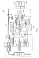
- Figure 1 is a block diagram of a hybrid battery 1000 of an embodiment according to the present invention.
- a hybrid battery 1000 of an embodiment according to the present invention contains a first power source 1100, a second power source 1200, a sense resistor 1300, and a fuel gauge circuit 1400.
- the first power source 1100 contains a first battery cell 1110, a first main protection circuit 1120, first pre-charge/charge/discharge switches 1130, a first sub protection circuit 1140 (or first support protection circuit or first auxiliary protection circuit), a first fuse 1150, and a first temperature sensor 1160.
- the first battery cell 1110 may be formed of at least one rechargeable battery (i.e., secondary battery) that can be charged and discharged and connected in series or parallel.
- the rechargeable battery can include one or more of a cylinder type lithium ion battery, a rectangular type lithium ion battery, a pouch type lithium polymer battery, a pouch type lithium ion battery, or any equivalent or other suitable batteries known to those skilled in the art.
- the first main protection circuit 1120 perceives (or detects) the charge voltage or the discharge voltage of the first battery cell 1110, and provides the result to the fuel gauge circuit 1400. Also, the first main protection circuit 1120 turns on or turns off the first pre-charge/charge/discharge switches 1130 using one or more control signals (for example, a charge stop signal, a charge start signal, a discharge stop signal and a discharge start signal) of the fuel gauge circuit 1400. Moreover, the first main protection circuit 1120 detects an electric current from the sense resistor 1300, and turns off the first pre-charge/charge/ discharge switches 1130 if overcurrent (i.e., too much current) is detected. The working relationship between the first main protection circuit 1120 and the first pre-charge/charge/discharge switches 1130 will be described below in detail.
- the first pre-charge/charge/discharge switches 1130 include three switches that are connected in series in the charge and discharge path between the positive terminal (B+) of the first battery cell 1110 and the pack positive terminal (P+) (i.e., the positive terminal of the hybrid battery 1000).
- the first precharge/charge/discharge switches 1130 are turned on and turned off by the control signal of the first main protection circuit 1120. In other embodiments, the first precharge switch may not be included.
- the first sub protection circuit 1140 blocks or interrupts the charge and discharge path by cutting off the first fuse 1150 in case that the first main protection circuit 1120 and/or the first pre-charge/charge/discharge switches 1130 are not operated properly.
- the first fuse 1150 is connected in series with the charge and discharge path between the first pre-charge/charge/discharge switches 1130 and the pack positive terminal (P+). As described above, the first fuse 1150 can be cut off by the control signal of the first sub protection circuit 1140. In one embodiment, once cut off, the first fuse 1150 cannot be restored.
- the first temperature sensor 1160 detects the temperature of the first battery cell 1110 and outputs to the fuel gauge circuit 1400.
- the fuel gauge circuit 1400 outputs the charge stop signal or the discharge stop signal to the first main protection circuit 1120 when the temperature from the first temperature sensor 1160 is more than the allowable temperature, and the first main protection circuit 1120 blocks or interrupts the charge and discharge path by turning off at least one of the first precharge/charge/discharge switches 1130.
- the fuel gauge circuit 1400 uses the temperature detected by the first temperature sensor for the purposes of capacity correction of the battery.
- the correction method of the capacity of the battery using or based on temperature is already known to those skilled in the art, so that it will not be described in detail.
- the second power source 1200 contains a second battery cell 1210, a second main protection circuit 1220, second pre-charge/charge/discharge switches 1230, a second sub protection circuit 1240, a second fuse 1250, and a second temperature sensor 1260.
- the second battery cell 1210 may be formed of at least one rechargeable battery (i.e., secondary battery) that can be charged and discharged and connected in series or parallel.
- the secondary battery can be a cylinder type lithium ion battery, a rectangular type lithium ion battery, a pouch type lithium polymer battery, a pouch type lithium ion battery, or any equivalent or other suitable batteries known to those skilled in the art.
- the first battery cell 1110 of the first power source 1100 and the second battery cell 1210 of the second power source 1200 can be different from each other in the shape, chemical property, capacity, charge voltage and/or charge electric current.
- the second battery cell 1210 can be a rectangular type lithium ion battery, a pouch type lithium polymer battery, a pouch type lithium ion battery or any equivalent or other suitable battery.
- the first battery cell 1110 is a lithium battery cell
- the second battery cell 1210 can be a nickel-cadmium battery, a nickel- hydrate battery, or any equivalent or other suitable battery.
- the capacity of the first power source 1100 and the capacity of the second power source 1200 can be different from each other.
- the charge voltage and the charge current of the first power source 1100 and the charge voltage and the charge current of the second power source 1200 can be different from each other.
- the second main protection circuit 1220 perceives (or detects) the charge voltage or the discharge voltage of the second battery cell 1210, and provides the result to the fuel gauge circuit 1400. Also, the second main protection circuit 1220 turns on or turns off the second pre-charge/charge/discharge switches 1230 using one or more control signals (for example, a charge stop signal, a charge start signal, a discharge stop signal and a discharge start signal) of the fuel gauge circuit 1400. Moreover, the second main protection circuit 1220 detects an electric current from the sense resistor 1300, and turns off the second pre-charge/charge/discharge switches 1230 if overcurrent (i.e., too much current) is detected.
- overcurrent i.e., too much current
- the second pre-charge/charge/discharge switches 1230 include three switches that are connected in series in the charge and discharge path between the positive terminal (B+) of the second battery cell 1210 and the pack positive terminal (P+) (i.e., the positive terminal of the hybrid battery 1000).
- the second pre-charge/charge/discharge switches 1230 are turned on and turned off by the control signal of the second main protection circuit 1220. In other embodiments, the second pre-charge switch may not be included.
- the second sub protection circuit 1240 cuts off the second fuse 1250 in case that the second main protection circuit 1220 and/or the second precharge/charge/discharge switches 1230 are not operated properly.
- the second fuse 1250 is connected in series with the charge and discharge path between the second pre-charge/charge/discharge switches 1230 and the pack positive terminal (P+).
- the second fuse 1250 can be cut off by the control signal from the second sub protection circuit 1240. In one embodiment, once cutoff, the second fuse 1250 cannot be restored.
- the second temperature sensor 1260 detects the temperature of the second battery cell 1210 and outputs to the fuel gauge circuit 1400.
- the fuel gauge circuit 1400 outputs the charge stop signal or the discharge stop signal to the second main protection circuit 1220 when the temperature from the second temperature sensor 1260 is more than the allowable temperature, and the second main protection circuit 1220 blocks or interrupts the charge and discharge path by turning off at least one of the second pre-charge/charge/discharge switches 1230.
- the fuel gauge circuit 1400 performs capacity correction using the temperature from the second temperature sensor 1260.
- the second fuse 1250 (or the first fuse 1150) and the second sub protection circuit 1240 (or the first sub protection circuit 1140) may not be used.
- the first fuse 1150 (or the second fuse 1250) is located between the node N1 and the pack positive terminal (P+)
- the first sub protection circuit 1140 (or the second sub protection circuit 1240) can be operated or activated when the first main protection circuit 1120 or the second main protection circuit 1220, or both the main protection circuits 1120 and 1220, are not operated normally (or properly).
- the second fuse 1250 and the second sub protection circuit 1240 (or the first fuse 1150 and the first sub protection circuit 1140) may be omitted because only one fuse can be used to interrupt the current path for both the first and second batteries.
- the sense resistor 1300 is located in the charge and discharge path between the node N2 and the pack negative terminal (P-).
- the sense resistor converts an applied voltage to an electric current and provides the electric current to the fuel gauge circuit 1400, the first main protection circuit 1120 and the second main protection circuit 1220.
- the sense resistor 1300 notifies the overcurrent condition to the first main protection circuit 1120 and the second main protection circuit 1220, and allows the fuel gauge circuit 1400 to calculate the accumulated discharge amount.
- Figure 1 illustrates that one sense resistor 1300 is used, but in other embodiments, a plurality of sense resistors (e.g., three sense resistors) 1300 can be used.
- the sense resistor 1300 can be located between the negative terminal (B-) of the first battery cell 1110 and the node N2, the negative terminal (B-) of the second battery cell 1210 and node N2, and/or the node N2 and the pack negative terminal (P-).
- the overcurrent and the accumulated discharge amount of each of the first battery cell 1110 and the second battery cell 1210 can be detected more accurately, and also the total overcurrent and the accumulated discharge amount of both the first battery cell 1110 and the second battery cell 1210 can be detected more accurately.
- a problem is that the pack manufacturing cost increases when multiple sense resistors are used.
- the fuel gauge circuit 1400 can include a fuel gauge IC or a micro computer that include a central processing unit (CPU), memory such as RAM or ROM, and/or input and output ports.
- the fuel gauge circuit 1400 as explained receives the voltage information of the first battery cell 1110 from the first main protection circuit 1120 of the first power source 1100, receives the voltage information of the second battery cell 1210 from the second main protection circuit 1220 of the second power source 1200, and receives the current information (accumulated discharge amount) from the sense resistor 1300.
- the fuel gauge circuit 1400 receives the temperature information of the first battery cell 1110 from the first temperature sensor 1160 of the first power source 1100 and receives the temperature information of the second battery cell 1210 from the second temperature sensor 1260 of the second power source 1200.
- the fuel gauge circuit 1400 calculates full charge capacity (FCC) and/or the remaining capacity (RC) of the first power source 1100 and/or the second power source 1200 by performing coulomb count (current integration) based on the accumulated discharge amount obtained from the sense resistor 1300.
- the full charge capacity calculation method of the battery will be described in detail below.
- the fuel gauge circuit 1400 calculates remaining capacity of the first power source 1100 and/or the second power source 1200, and transmits the combined remaining capacity of the two batteries to an external system 1500 having a load 1510 through the communication line such as the SMBus. Therefore, the external system 1500, through the load 1510, perceives as though it is connected to a single battery, and it is relatively easy to detect a total capacity.
- the fuel gauge circuit 1400 obtains the charge voltage information and/or the discharge voltage information from the first main protection circuit 1120 of the first power source 1100.
- the fuel gauge circuit 1400 sends the stop charge signal to the first main protection circuit 1120, and when the discharge voltage is determined to be an overdischarge voltage, the fuel gauge circuit 1400 sends the discharge stop signal to the first main protection circuit 1200.
- the first main protection circuit 1120 turns off the first charge switch when the charge stop signal input is received and turns off the first discharge switch when the discharge stop signal input is received.
- the fuel gauge circuit 1400 obtains the charge voltage information and the discharge voltage information from the second main protection circuit of the second power source 1200.
- the fuel gauge circuit 1400 sends the charge stop signal to the second main protection circuit 1220
- the discharge voltage is determined to be an overdischarge voltage
- the fuel gauge circuit 1400 sends the discharge stop signal to the second main protection circuit 1220.
- the second main protection circuit 1220 turns off the second charge switch, and turns off the second discharge switch when the discharge stop signal is received.
- the second main protection circuit 1220 turns off the second charge switch when the charge stop signal is inputted, and turns off the second discharge switch when the discharge stop signal is inputted.
- the fuel gauge circuit 1400 controls the first power source 1100 and the second power source 1200 such that only one of the first power source 1100 or the second power source 1200 provides power to an external system. For example, in one embodiment, when the fuel gauge circuit 1400 controls the first power source 1100 to provide electricity to the load 1510, the fuel gauge circuit 1400 outputs the charge stop signal and the discharge stop signal to the second power source 1200, such that the second power source 1200 is not charged by the first power source 1100. Of course, the discharge of the second power source 1200 is also blocked or interrupted.
- the fuel gauge circuit 1400 controls the second power source 1200 to provide electricity to the load 1510
- the fuel gauge circuit 1400 outputs the charge stop signal and the discharge stop signal to the first power source 1100, such that the first power source 1100 is not charged by the second power source 1200. From this, the discharge of the first power source 1100 is also blocked or interrupted.
- the above operation takes place when the load 1510 is connected to the pack positive terminal (P+) and the pack negative terminal (P-).
- the operation or mechanism
- the fuel gauge circuit 1400 may control the first power source 1100 and the second power source 1200 to be charged in sequence or to be charged concurrently.
- the fuel gauge circuit 1400 outputs the charge stop signal or the discharge stop signal to the first main protection circuit 1120 when the temperature information obtained from the first temperature sensor 1160 of the first power source 1100 is higher than an allowable/acceptable temperature, such that the first main protection circuit 1120 blocks or interrupts the charge and discharge path. In other words, the first main protection circuit 1120 turns off the first charge switch or the first discharge switch.
- the fuel gauge circuit 1400 outputs the charge stop signal or the discharge stop signal to the second main protection circuit 1220 when the temperature information obtained from the second temperature sensor 1260 of the second power source 1200 is higher than an allowable/acceptable temperature, such that the second main protection circuit 1220 blocks or interrupts the charge and discharge path. In other words, the second main protection circuit 1220 turns off the second charge switch or the second discharge switch.
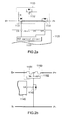
- Figure 2a is a circuit diagram that illustrates a relationship between the first precharge/charge/discharge switches 1130 and the first main protection circuit 1120 in a hybrid battery
- Figure 2b is a circuit diagram that illustrates a relationship between the first fuse 1150 and the first sub protection circuit 1140 of an embodiment according to the present invention.
- circuitry and configuration shown in Figure 2a is that of the first main protection circuit 1120 and the first pre-charge/charge/discharge switches 1130, the circuitry and configuration can be applied equally as well to the second power source 1200. Therefore, the second main protection circuit 1220 and the second pre-charge/charge/discharge switches 1230 will not be discussed in detail.
- the first charge switch 1131, the first precharge switch (or first preparation charge switch) 1132 and the first discharge switch 1133 are connected one after the other in the charge and discharge path between the positive terminal (B+) of the first battery cell 1110 and the pack positive terminal (P+).
- the first charge switch 1131 and the first discharge switch 1133 are connected in series with the charge and discharge path, and the first precharge switch 1132 is connected in parallel to the charge and discharge path.
- all switches 1131, 1132, 1133 are P channel field effect transistors (FETs) including the parasitic diode from the drain to the source but the present invention is not limited thereto.
- FETs P channel field effect transistors
- the drain of the first charge switch 1131 is connected with the positive terminal (B+) of the first battery cell 1110, and the drain of the first discharge switch 1133 is connected with the pack positive terminal (P+).
- the source of the first precharge switch 1132 is connected with the source of the first charge switch 1131 and the source of the first discharge switch 1133, and the drain is connected with the drain of the first charge switch 1131 though the resistor R.
- a capacitor C may be used for power source change control.
- the gate of the first charge switch 1131, the gate of the first precharge switch 1132, and the gate of the first discharge switch 1133 are each controlled by the first main protection circuit 1120.
- the first main protection circuit 1120 applies a low signal to the gate of the first charge switch 1131 through the CFET terminal
- the first charge switch 1131 is turned on
- the first main protection circuit 1120 applies a low signal to the gate of the first precharge switch 1132 through the PCFET terminal
- the first precharge switch 1132 is turned on
- a low signal is applied to the gate of the first discharge switch 1133 through the DFET terminal
- the first main protection circuit 1120 when the first main protection circuit 1120 applies a high signal to the gate of the first charge switch 1131 through the CFET terminal, the first charge switch 1131 is turned off, when the first main protection circuit 1120 applies a high signal to the gate of the first precharge switch 1132 through the PCFET terminal, the first precharge switch 1132 is turned off, and when the first main protection circuit 1120 applies a high signal to the gate of the first discharge switch 1133 through the DFET terminal, the first discharge switch 1133 is turned off.
- the first main protection circuit 1120 includes a FET control circuit 1122 to control the gate voltage of each of the switches 1131, 1132, and 1133.
- the charging of the first battery cell 1110 is stopped (discharging is possible by the parasitic diode) when the first main protection circuit 1120 turns off the first charge switch 1131
- the discharging of the first battery cell 1110 is stopped (charging is possible by the parasitic diode) when the first main protection circuit 1120 turns off the first discharge switch 1133.
- the first precharge switch 1132 supplies charging current at a lower level to the battery cell during a period of time (e.g., a predetermined period of time) to have the voltage level of the first battery cell 1110 to be sufficient for fast charging.
- the operation of the first charge switch 1131, the first precharge switch 1132, and the first discharge switch 1133 is already known to those skilled in the art, so that additional explanation will be omitted.
- Figure 2b illustrates the first sub protection circuit 1140 of the first power source 1100 and the first fuse 1150. Such configuration can also be applied to the second power source 1200. Therefore, the description of the configuration and operation of the second sub protection circuit 1240 of the second power source 1200 and the second fuse 1250 will not be provided.
- the first fuse 1150 is located in the charge and discharge path between the positive terminal (B+) of the first battery cell 1110 and the pack positive terminal (P+). Also, the first switch 1142 is connected in the charge and discharge path between the negative terminal (B-) of the first battery cell 1110 and the pack positive terminal (P-) to operate the first fuse 1150. Further, the first switch 1142 is connected with the CO terminal of the first sub protection circuit 1140.
- the first fuse 1150 includes at least one temperature fuse 1151 and a heating resistor 1152 which cuts the temperature fuse 1151 through heating and melting.
- the first switch is an N channel field effect transistor but the present invention is not limited thereto.
- the first sub protection circuit 1140 applies a high signal to the gate of the first switch 1142 through the CO terminal, the first switch 1142 is turned on, and a charge current or a discharge current flows from the positive terminal (B+ or P+) to the negative terminal (B- or P-) through the temperature fuse 1151, the heating resistor 1152, and the source and drain of the first switch 1142. Therefore, the heating resistor 1152 is heated so that the temperature fuse 1151 is cut off, and the charge and discharge path is interrupted (e.g., permanently interrupted).
- the first sub protection circuit 1140 operates when the first main protection circuit 1120 or the first precharge/charge/discharge switch 1130 is not operated normally.
- Figure 3 is a graph illustrating a full charge capacity calculation method of the battery.
- the X axis is the charge and discharge time
- Y axis is the Relative State of Charge (RSOC), which is a relative charge status/condition of the battery.
- RSOC Relative State of Charge
- RC Remain Capacity that means the remaining capacity of the battery
- DCR Discharge Counter Register that means the accumulated discharge amount
- EDV End of Discharge Voltage that means a discharge voltage level.
- the remaining capacity and the full charge capacity are the same when the battery is fully charged.
- the calculated new full charge capacity equals a sum of the accumulation discharge amount DCR and the EDV1(%)*FCCold when the battery has been discharged to the discharge voltage level (EDV1).
- EDV1 (%) is a percentage of the remaining capacity (or relative state of charge) at the discharge voltage level (EDV1)
- FCCold means a previous total full charge capacity
- Figure 4 is a block diagram that illustrates the fuel gauge circuit 1400 and nearby circuits of the hybrid battery 1000 in an embodiment according to the present invention.
- the first power source 1100 includes the first battery cell 1110 and the first main protection circuit 1120 that detects the voltage of the first battery cell 1110 and outputs the detected voltage to the fuel gauge circuit 1400.
- the first main protection circuit 1120 includes an analog-to-digital converter for converting the analog voltage data of the first battery cell 1110 to the digital voltage data, and for outputting the digital voltage data to the fuel gauge circuit 1400.
- the second power source 1200 includes the second battery cell 1210 and the second main protection circuit 1220 that detects the voltage of the second battery cell 1210 and outputs the detected voltage to the fuel gauge circuit 1400.
- the second main protection circuit 1220 includes an analog-to-digital converter for converting the analog voltage data of the second battery cell 1210 to the digital voltage data, and for outputting the digital voltage data to the fuel gauge circuit 1400.
- the sense resistor 1300 counts the electric charge that goes through it, and outputs the count to the fuel gauge circuit 1400.
- the sense resistor 1300 outputs the analog data to the fuel gauge circuit 1400, and the fuel gauge circuit 1400 converts the analog data to the digital data using an A-D converter 1432.
- the fuel gauge circuit 1400 includes a first discharge voltage level detection unit 1410, a second discharge voltage level detection unit 1420, an accumulated discharge amount calculation unit 1430, a capacity calculation unit 1440, a memory 1450, and a communication processing unit 1460.
- the fuel gauge circuit 1400 includes additional circuitry to control the charging and discharging states of the first power source 1100 and the second power source 1200.
- additional circuitry is not essential to a complete understanding of the present invention, it will not be described in detail.
- the first discharge voltage level detection unit 1410 detects at least two discharge voltage levels (EDV1, EDV2) during the discharge of the first power source 1100, and transmits the determined discharge voltage levels to the capacity calculation unit 1440.
- the first discharge voltage level detection unit 1410 may not operate when the first power source 1100 is not discharging.
- the discharge voltage level EDV1 is set to be higher than the other discharge voltage level EDV2.
- the second discharge voltage level detection unit 1420 detects at least two discharge voltage levels (EDV1, EDV2) during the discharge of the second power source 1200, and transmits the determined discharge voltage levels to the capacity calculation unit 1440.
- the second discharge voltage level detection unit 1420 may not operate when the second power source 1200 is not discharging.
- the discharge voltage level EDV1 is set to be higher than the other discharge voltage level EDV2.
- the accumulated discharge amount calculation unit 1430 calculates the accumulated discharge amount at the discharge voltage levels (EDV1, EDV2) using the current information from the sense resistor 1300, and transmits the accumulated discharge amount to the capacity calculation unit 1440.
- the analog-to-digital converter 1432 is located in front of (or before) the accumulated discharge amount calculation unit 1430 to convert the analog data of the sense resistor 1300 to digital data.
- the capacity calculation unit 1440 calculates the full charge capacity (FCC) of the first power source 1100 or the second power source 1200 at at least two discharge voltage levels (EDV1, EDV2), respectively.
- the capacity calculation unit 1440 of the fuel gauge circuit 1400 calculates the first accumulation discharge capacity (DCR1) (or first accumulated discharge amount) using the current information from the sense resistor 1300 when the voltage level of the currently discharging power source among the first power source 1100 or the second power source 1200 becomes the first discharge voltage level EDV1. Further, the capacity calculation unit 1440 calculates the first full charge capacity (FCCnew1) by adding the first accumulation discharge capacity (DCR1) (or first accumulated discharge amount) with a first capacity at the first discharge voltage level (EDV1). The first capacity equals to a product of the assigned percentage (EDV1 (%)) for the remaining capacity at the first discharge voltage level (EDV1) and a previous full charge capacity (FCCold).
- the capacity calculation unit 1440 of the fuel gauge circuit 1400 calculates the second accumulation discharge capacity (DCR2) (or second accumulated discharge amount) using the current information from the sense resistor 1300 when the voltage level becomes the second discharge voltage level (EDV2) that is smaller than the first discharge voltage level (EDV1).
- the capacity calculation unit 1440 calculates the second full charge capacity (FCCnew2) by adding the second accumulation discharge capacity (DCR2) with a second capacity at the second discharge voltage level (EDV2).
- the second capacity equals to a product of the assigned percentage (EDV2 (%)) for the remaining capacity at the second discharge voltage level (EDV2) and a previous full charge capacity (FCCold).
- the full charge capacity of the actually discharging battery is calculated by discharging selected one of the first power source 1100 or the second power source 1200. For example, when only the first power source 1100 is discharging, the full charge capacity of the first power source 1100 is calculated, and when only the second power source 1200 is discharging, the full charge capacity of the second power source 1200 is calculated.
- the capacity calculation unit 1440 calculates a total full charge capacity of the hybrid battery 1000 by adding the calculated full charge capacity (namely, the first full charge capacity or the second full charge capacity) of the first power source 1100 and already calculated and stored full charge capacity of the second power source 1200.
- the capacity calculation unit 1440 calculates a total full charge capacity of the hybrid battery 1000 by adding the calculated full charge capacity (namely, the first full charge capacity or the second full charge capacity) of the second power source 1200 and the already calculated and stored full charge capacity of the first power source 1100.
- the memory 1450 stores (or updates) a full charge capacity of the first power source 1100 or the second power source 1200 while the full charge capacity is continuously calculated. For example, the full charge capacity of the first power source 1100 is continuously calculated and stored while the first power source 1100 is being discharged, and the full charge capacity of the second power source 1200 that is not discharging continues to remain as the previously calculated full charge capacity. Also, the full charge capacity of the second power source 1200 is continuously calculated and stored in the memory 1450 while the second power source 1200 is being discharged. The full charge capacity of the first power source 1100 that is not discharging continues to remain as the previously calculated full charge capacity.
- the memory provides the full charge capacity data of the non-discharging battery when the capacity calculation unit 1440 calculates the full charge capacity of the discharging battery, and adds with the full charge capacity of the non-discharging battery.
- the program including algorithms, variables, and constants, etc. can be stored in the memory 1450 and the explanation will be omitted because it is known to those skilled in the art.
- the communication processing unit 1460 can be a device using an interface method such as an SMBus that includes clock and data lines that are used primarily in the smart battery field.
- the communication processing unit 1460 allows the user to find out information such as the remaining capacity information of the battery through an external system 1500 by transmitting information such as the voltage and current of the battery, full charge capacity, and the remaining capacity to an external system 1500 (For example, the load such as a lap top computer).
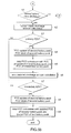
- Figure 5a and Figure 5b are flow charts that illustrate the full charge capacity calculation method of a hybrid battery of an embodiment according to the present invention.
- the full charge capacity calculation method of a hybrid battery of an embodiment according to the present invention includes (a1) deciding the discharging condition/status of the first power source 1100, (a2) calculating accumulated discharge amount of the first power source 1100 while the first power source 1100 is being discharged, (a3) deciding whether the first power source 1100 reached a primary discharge voltage level or not, (a4) calculating the full charge capacity of the first power source 1100 when the first power source 1100 reaches the primary discharge voltage level and storing the full charge capacity of the first power source 1100, (a5) calculating the total full charge capacity of the hybrid battery 1000 by adding the calculated full charge capacity of the first power source 1100 to the already stored full charge capacity of the second power source 1200, (a6) calculating an accumulated discharge amount of the first power source 1100 continuously, (a7) deciding whether the first power source 1100 reached the secondary discharge voltage level, (a8) calculating the full charge capacity of the first power source 1100 when the first power source 1100 reaches the secondary discharge voltage level
- the full charge capacity calculation method of a hybrid battery of an embodiment according to the present invention includes (b1) deciding the discharging condition/status of the second power source 1200, (b2) calculating accumulated discharge amount of the second power source 1200 while the second power source 1200 is being discharged, (b3) deciding whether the second power source 1200 reached a primary discharge voltage level or not, (b4) calculating the full charge capacity of the second power source 1200 when the second power source 1200 reaches the primary discharge voltage level and storing the full charge capacity of the second power source 1200, (b5) calculating the total full charge capacity of the hybrid battery 1000 by adding the calculated full charge capacity of the second power source 1200 to the already stored full charge capacity of the first power source 1100, (b6) calculating an accumulated discharge amount of the second power source 1200 continuously, (b7) deciding whether the second power source 1200 reached the secondary discharge voltage level, (b8) calculating the full charge capacity of the second power source 1200 when the second power source 1200 reaches the secondary discharge voltage level
- Figure 6 is a graph that illustrates a full charge capacity calculation method of a hybrid battery of an embodiment according to the present invention.
- the full charge capacity is calculated at least two different discharge voltage levels (EDV1, EDV2) while discharging the first power source 1100 or the second power source 1200. Therefore, the remaining capacity can be more accurately calculated by calculating the full charge capacity more accurately.
- a dotted line in Figure 6 illustrates the case where the remaining capacity is mis-calculated because of an incorrect calculation of the full charge capacity, and the solid line illustrates the case where the remaining capacity is accurately calculated by accomplishing the calculation of the full charge capacity.
- the fuel gauge circuit 1400 decides whether the first power source 1100 is being discharged or not. For example, the fuel gauge circuit 1400 can determine whether the first battery cell 1110 is discharging or charging by monitoring the inputted voltage (e.g., by comparing successive inputted voltages) from the first main protection circuit 1120 to determine whether the inputted voltage is becoming progressively smaller (discharging state) or progressively larger (charging state). Of course, there is no change in the inputted voltage when the first battery cell 1110 is not being charged or discharged.
- the fuel gauge circuit 1400 calculates the accumulated discharge amount by counting the amount of electric charges flowing through the sense resistor 1300.
- the sense resistor 1300 located in series in the charge and discharge path inputs the amount of current to the analog digital converter 1432 in accordance with the amount of current that flows through the sense resistor 1300, the analog digital converter 1432 converts this output to the digital data and outputs to the accumulated discharge amount calculation unit 1430.
- the accumulated discharge amount calculation unit 1430 calculates the accumulated discharge amount, and provides the accumulation data to the capacity calculation unit 1440.
- the fuel gauge circuit 1400 decides whether the first power source 1100 is at the primary discharge voltage level (EDV1) using the input information through the first discharge voltage level detection unit 1410.
- the fuel gauge circuit 1400 calculates the full charge capacity (FCCnew) by adding the value that equals to the accumulated discharge amount until the primary discharge voltage level (EDV1) is reached, and a product of the percentage for the remaining capacity at the primary discharge voltage level (EDV1(%)) and a total full charge capacity (FCC old).
- the capacity calculation unit 1440 stores the newly calculated full charge capacity (FCCnew) of the first power source 1100 in the memory 1450.
- the fuel gauge circuit 1400 calculates the total full charge capacity of the hybrid battery 1000 by adding the full charge capacity of the second power source 1200 stored in the memory 1450 and the full charge capacity of the first power source 1100 calculated using the above method.
- the fuel gauge circuit 1400 calculates the accumulated discharge amount of the first power source 1100 at a voltage below the primary discharge voltage level (EDV1) by using the sense resistor 1300.
- the fuel gauge circuit 1400 decides whether the first power source 1100 is at the secondary discharge voltage level (EDV2) by using the input information through the first discharge voltage level detection unit 1410.
- the fuel gauge circuit 1400 calculates the full charge capacity (FCCnew) by adding the value that equals to the accumulated discharge amount until the secondary discharge voltage level (EDV2), and a product of the percentage for the remaining capacity at the secondary discharge voltage level (EDV2(%)) and a total full charge capacity (FCC old).
- the capacity calculation unit 1440 stores the newly calculated full charge capacity of the first power source 1100 in the memory 1450.
- the fuel gauge circuit 1400 calculates the total full charge capacity of the hybrid battery 1000 by adding the full charge capacity of the second power source 1200 stored in the memory 1450 and the full charge capacity of the first power source 1100 calculated using the above described method.
- the fuel gauge circuit 1400 corrects the remaining capacity of the battery and gives notice to the external system 1500 through the communication processing unit 1460, but the algorithms are a generally known technique so that the explanation will be omitted.
- the full charge capacity calculation of the second power source 1200 is similar to the above described method of the full charge capacity calculation of the first power source 1100.
- the fuel gauge circuit 1400 decides whether the second power source 1200 is being discharged or not.
- the fuel gauge circuit 1400 calculates the accumulated discharge amount by counting the amount of electric charges flowing through the sense resistor 1300.
- the fuel gauge circuit 1400 decides whether the second power source 1200 is at the primary discharge voltage level (EDV1) using the input information through the first discharge voltage level detection unit 1410.
- the fuel gauge circuit 1400 calculates the full charge capacity (FCCnew) by adding the value that equals to the accumulated discharge amount until the primary discharge voltage level (EDV1) is reached, and a product of the percentage for the remaining capacity at the primary discharge voltage level (EDV1 (%)) and a total full charge capacity (FCCold).
- the capacity calculation unit 1440 stores the newly calculated full charge capacity (FCCnew) of the second power source 1200 to the memory 1450.
- the fuel gauge circuit 1400 calculates the total full charge capacity of the hybrid battery 1000 by adding the full charge capacity of the second power source 1200 and the full charge capacity of the first power source 1100 stored in the memory 1450.
- the fuel gauge circuit 1400 calculates the accumulated discharge amount of the second power source 1200 at a voltage below the primary discharge voltage level (EDV1) by using the sense resistor 1300.
- the fuel gauge circuit 1400 decides whether the second power source 1200 is at the secondary discharge voltage level by using the input information through the first discharge voltage level detection unit 1410.
- the fuel gauge circuit 1400 calculates the full charge capacity (FCCnew) by adding the value that equals to the accumulated discharge amount until the secondary discharge voltage level (EDV2) and a product of the percentage for the remaining capacity at the secondary discharge voltage level (EDV2(%)) and a total full charge capacity (FCCold).
- the capacity calculation unit 1440 stores the newly calculated full charge capacity of the second power source 1200 in the memory 1450.
- the fuel gauge circuit 1400 calculates the total full charge capacity of the hybrid battery 1000 by adding the full charge capacity of the second power source 1200 and the full charge capacity of the first power source 1100 stored in the memory 1450.
- the fuel gauge circuit 1400 corrects the remaining capacity of the battery and gives notice to the external system 1500 through the communication processing unit 1460, but the algorithms include a generally known technique so that the explanation will be omitted.
- a hybrid battery and full charge capacity calculation method thereof can calculate the remaining capacity of the battery more accurately by calculating the full charge capacity of the battery at at least two discharge voltage levels.
- a hybrid battery and full charge capacity calculation method thereof can calculate a total full charge capacity of a hybrid battery by adding the already stored full charge capacity of another battery that is not discharging after calculating the full charge capacity of the discharging battery. Therefore, the total remaining capacity of the whole hybrid battery can be calculated more accurately.
- a hybrid battery and full charge capacity calculation method thereof is not limited to the exemplary embodiments, instead, those skilled in the art would appreciate that the invention can be altered in various different ways without departing from the spirit or scope of the present invention.
- the exemplary embodiments have been described primarily in reference to a hybrid battery having two batteries, the present invention is broadly applicable to hybrid batteries including any suitable number of batteries greater than two (e.g., three).
- the exemplary embodiments have been described primarily in reference to calculating a full charge capacity at two discharge voltage levels, the present invention is broadly applicable to calculating a full charge capacity at more than two (e.g., three) discharge voltage levels for each battery in the hybrid battery.
- the scope of the invention is to be defined by the appended claims and their equivalents.
Landscapes
- Engineering & Computer Science (AREA)
- Power Engineering (AREA)
- Physics & Mathematics (AREA)
- General Physics & Mathematics (AREA)
- Manufacturing & Machinery (AREA)
- Chemical & Material Sciences (AREA)
- Chemical Kinetics & Catalysis (AREA)
- Electrochemistry (AREA)
- General Chemical & Material Sciences (AREA)
- Secondary Cells (AREA)
- Charge And Discharge Circuits For Batteries Or The Like (AREA)
Abstract
Description
- The present invention relates to a hybrid battery and full charge capacity calculation method thereof.
- Generally, a portable electronic device receives a supply of power from a chargeable battery, and a usable time of the portable electronic device depends on the usable time of the battery as the power supply. Therefore, the battery is charged frequently to extend the usable time of the portable electronic device.
- To maximize the usable time of the portable electronic device, one known method is to mount two batteries to a portable electronic device. For example, two batteries that have the same size and the same chemical property can be mounted to the same portable electronic device.
- However, this method makes the price of the battery increase because not only the circuit used to control the charge and discharge has to be installed to each battery but also the fuel gauge circuit or the micro computer for calculating the remaining capacity of each battery is also provided.
- Also, such conventional battery needs extra space because the shape and chemical property of the battery cells that are installed in each battery are typically completely the same, such that there is a problem of reduced energy efficiency per volume.
- A quantity (or concept) known as the full charge capacity (FCC) is used as a standard capacity to indicate the accurate remaining capacity (RC) of the battery. In this case, the remaining capacity illustrates the relative state of charge (RSOC) as a percentage of the current full charge capacity. The full charge capacity represents the chargeable maximum capacity of the battery and it gradually becomes smaller as the number of charge and discharge cycles increases. Therefore, the full charge capacity is calculated as the number of charge and discharge cycles increases. According to a conventional calculation method, the full charge capacity is calculated by starting to discharge the battery when the battery is fully charged, and keeping track of the total amount of discharge until the voltage level of the battery reaches an end of discharge voltage level (EDV). Then, the total amount of discharge, which is calculated until very close to the full discharge, is used as the standard capacity to calculate the full charge capacity.
- However, according to such conventional method of calculating the full charge capacity, the capacity is calculated at one discharge voltage level prior to the complete discharging, and the remaining capacity is calculated therefrom. Hence, it is difficult to calculate the remaining capacity of the battery when the battery is recharged prior to reaching the full discharge voltage level.
- In embodiments according to the present invention, a hybrid battery and full charge capacity calculation method of the hybrid battery is provided. According to the method, the voltage level of the currently discharging battery is detected, and a full charge capacity is calculated at at least two discharge voltage levels. Then, the calculated full charge capacity of the discharging battery and a full charge capacity of a non-discharging battery are added together so that the remaining capacity can be accurately calculated.
- Aspects according to embodiments of the present invention include a hybrid battery having at least two batteries that are different in at least one of the shape, chemical property, capacity or charge voltage. Also, aspects according to embodiments of the present invention include a hybrid battery having one circuit for capacity calculation and/or power control.
- Other aspects according to embodiments of the present invention provide a hybrid battery and full charge capacity calculation method thereof. According to an exemplary embodiment, a remaining capacity of a hybrid battery can be accurately calculated by sensing the discharging voltage of a currently discharging battery, calculating full charge capacity at at least two discharge voltage levels, and adding the full charge capacity of the currently discharging battery and the full charge capacity of the currently non-discharging battery together to calculate a total full charge capacity for the hybrid battery.
- In an exemplary embodiment according to the present invention, a hybrid battery includes: a first power source adapted to output a first voltage; a second power source, which is parallel to the first power source and adapted to output a second voltage; a sense resistor, which is in series with the first power source and the second power source and adapted to sense and output current information of at least one of the first power source or the second power source; and a fuel gauge circuit adapted to calculate a first accumulated discharge amount using the current information from the sense resistor when a voltage of a currently discharging one of the first power source or the second power source reaches a first discharge voltage level, and to add a first capacity corresponding to the first discharge voltage level to the first accumulated discharge amount to calculate a first full charge capacity.
- The first capacity may be calculated by multiplying a previous full charge capacity with a percentage of remaining capacity corresponding to the first discharge voltage level.
- The fuel gauge circuit may be further adapted to calculate a second accumulated discharge amount using the current information from the sense resistor when the voltage of the currently discharging one of the first power source or the second power source reaches a second discharge voltage level, wherein the second discharge voltage level is lower than the first discharge voltage level, and to calculate a second full charge capacity by adding a second capacity corresponding to the second discharge voltage level to the second accumulated discharge amount.
- The second capacity may be calculated by multiplying a previous full charge capacity with a percentage of remaining capacity corresponding to the second discharge voltage level.
- The fuel gauge circuit may include: a first discharge voltage level detector for detecting at least two discharge voltage levels different from each other while the first power source is discharging; a second discharge voltage level detector for detecting at least two discharge voltage levels different from each other while the second power source is discharging; an accumulated discharge amount calculator for calculating an accumulated discharge amount using the current information from the sense resistor; and a capacity calculator for calculating a full charge capacity by adding remaining capacity corresponding to one of the discharge voltage levels to the accumulated discharge amount when the discharge voltage level obtained from the first discharge voltage level detector or the second discharge voltage level detector reaches a preset discharge voltage level.
- The capacity calculator may calculate the first capacity by multiplying a percentage of remaining capacity corresponding to the discharge voltage level with a previous full charge capacity.
- The fuel gauge circuit, after calculating the full charge capacity of the discharging one of the first power source or the second power source, may add a previously stored full charge capacity of a currently non-discharging one of the first power source or the second power source to calculate a new total full charge capacity.
- The first power source and the second power source may include rechargeable batteries.
- At least one of the first power source or the second power source may include at least one of a cylinder type lithium ion battery, a rectangular type lithium ion battery, a pouch type lithium polymer battery, and a pouch type lithium ion battery.
- The first power source and the second power source may be different from each other in at least one of shape, chemical property, capacity or charge/discharge voltage.
- Another exemplary embodiment according to the present invention provides a method of calculating a full charge capacity of a hybrid battery including a first power source and a second power source. The method includes calculating a first accumulated discharge amount of the first power source while the first power source is discharging, and determining whether a first discharge voltage level of the first power source has been reached; adding the first accumulated discharge amount of the first power source, which has been accumulated until the first discharge voltage level was reached for the first power source, to a first capacity of the first power source corresponding to the first discharge voltage level of the first power source, to calculate a first full charge capacity of the first power source; calculating a second accumulated discharge amount of the first power source while the first power source is discharging, and determining whether a second discharge voltage level of the first power source, which is lower than the first discharge voltage level of the first power source, has been reached; and adding the second accumulated discharge amount of the first power source, which has been accumulated until the second discharge voltage level was reached for the first power source, to a second capacity of the first power source corresponding to the second discharge voltage level of the first power source, to calculate a second full charge capacity of the first power source.
- The first capacity or the second capacity of the first power source may be obtained, respectively, by multiplying a percentage of remaining capacity of the first power source corresponding to the respective first discharge voltage level or the second discharge voltage level of the first power source with a previous full charge capacity of the first power source.
- After respective calculation of the first full charge capacity or the second full charge capacity of the first power source, the method may further include storing the first full charge capacity or the second full charge capacity, respectively, of the first power source in a memory.
- After respective calculation of the first full charge capacity or the second full charge capacity of the first power source, the method may further include adding the first full charge capacity or the second full charge capacity, respectively, of the first power source to a previously stored full charge capacity of the second power source, to calculate a total full charge capacity.
- The method may further include: calculating a first accumulated discharge amount of the second power source while the second power source is discharging, and determining whether a first discharge voltage level of the second power source has been reached; adding the first accumulated discharge amount of the second power source, which has been accumulated until the first discharge voltage level was reached for the second power source, to a first capacity of the second power source corresponding to the first discharge voltage level of the second power source, to calculate a first full charge capacity of the second power source; calculating a second accumulated discharge amount of the second power source while the second power source is discharging, and determining whether a second discharge voltage level of the second power source, which is lower than the first discharge voltage level of the second power source, has been reached; and adding the second accumulated discharge amount of the second power source, which has been accumulated until the second discharge voltage level was reached for the second power source, to a second capacity of the second power source corresponding to the second discharge voltage level of the second power source, to calculate a second full charge capacity of the second power source.
- The first capacity or the second capacity of the second power source may be obtained, respectively, by multiplying a percentage of remaining capacity of the second power source corresponding to the respective first discharge voltage level or the second discharge voltage level of the second power source with a previous full charge capacity of the second power source.
- After respective calculation of the first full charge capacity or the second full charge capacity of the second power source, the method may further include storing the first full charge capacity or the second full charge capacity, respectively, of the second power source in the memory.
- After respective calculation of the first full charge capacity or the second full charge capacity of the second power source, the method may further include adding the first full charge capacity or the second full charge capacity, respectively, of the second power source to a previously stored full charge capacity of the first power source, to calculate another total full charge capacity.
- Also, by adding the full charge capacity of a second power to the stored full charge capacity of the first power of non-discharging after each full charge capacity calculation step, it can be contained the step of calculating a total full charge capacity of the first power and a second power.
- A hybrid battery and full charge capacity calculation method thereof according to exemplary embodiments of the present invention may be used to accurately calculate the remaining capacity of the battery by newly calculating the full charge capacity of the battery at at least two discharge voltage levels.
- Also, a hybrid battery and full charge capacity calculation method thereof according to exemplary embodiments the present invention may be used to newly calculate a total full charge capacity of a hybrid battery by adding already (or previously) stored full charge capacity of a battery that is not currently discharging to a full charge capacity of the discharging battery after calculating the full charge capacity of the discharging battery. This way, a total remaining capacity calculation of a hybrid battery may be accurately performed.
- These and/or other aspects of the invention will become apparent and more readily appreciated from the following description of exemplary embodiments, taken in conjunction with the accompanying drawings of which:
- Figure 1 is a block diagram of a hybrid battery of an embodiment according to the present invention;
- Figure 2a is a circuit diagram that shows a relationship between precharge/charge/discharge switches and a main protection circuit in a hybrid battery;
- Figure 2b is a circuit diagram that illustrates a relationship between a fuse and a support protection circuit (or sub protection circuit or auxiliary protection circuit) of an embodiment according to the present invention;
- Figure 3 is a graph that explains the full charge capacity calculation method of the battery;
- Figure 4 is a block diagram that illustrates a fuel gauge circuit and nearby circuits thereof of an embodiment of a hybrid battery according to the present invention;
- Figure 5a and Figure 5b are flow charts that illustrate the full charge capacity calculation method of a hybrid battery of an embodiment according to the present invention; and
- Figure 6 is a graph that illustrates the full charge capacity calculation method of a hybrid battery of an embodiment according to the present invention.
- When at least two batteries are used together, a full charge capacity may be calculated for each battery, and a total full charge capacity may be calculated by adding the respective full charge capacities together. Exemplary embodiments of the present invention are related to such calculation method.
- Hereinafter, exemplary embodiments of the present invention will be described with reference to the accompanying drawings.
- Figure 1 is a block diagram of a
hybrid battery 1000 of an embodiment according to the present invention. - As illustrated in Figure 1, a
hybrid battery 1000 of an embodiment according to the present invention contains afirst power source 1100, asecond power source 1200, asense resistor 1300, and afuel gauge circuit 1400. - The
first power source 1100 contains afirst battery cell 1110, a firstmain protection circuit 1120, first pre-charge/charge/discharge switches 1130, a first sub protection circuit 1140 (or first support protection circuit or first auxiliary protection circuit), afirst fuse 1150, and afirst temperature sensor 1160. Thefirst battery cell 1110 may be formed of at least one rechargeable battery (i.e., secondary battery) that can be charged and discharged and connected in series or parallel. For example, the rechargeable battery can include one or more of a cylinder type lithium ion battery, a rectangular type lithium ion battery, a pouch type lithium polymer battery, a pouch type lithium ion battery, or any equivalent or other suitable batteries known to those skilled in the art. - The first
main protection circuit 1120 perceives (or detects) the charge voltage or the discharge voltage of thefirst battery cell 1110, and provides the result to thefuel gauge circuit 1400. Also, the firstmain protection circuit 1120 turns on or turns off the first pre-charge/charge/discharge switches 1130 using one or more control signals (for example, a charge stop signal, a charge start signal, a discharge stop signal and a discharge start signal) of thefuel gauge circuit 1400. Moreover, the firstmain protection circuit 1120 detects an electric current from thesense resistor 1300, and turns off the first pre-charge/charge/discharge switches 1130 if overcurrent (i.e., too much current) is detected. The working relationship between the firstmain protection circuit 1120 and the first pre-charge/charge/discharge switches 1130 will be described below in detail. - In one embodiment, the first pre-charge/charge/
discharge switches 1130 include three switches that are connected in series in the charge and discharge path between the positive terminal (B+) of thefirst battery cell 1110 and the pack positive terminal (P+) (i.e., the positive terminal of the hybrid battery 1000). The first precharge/charge/discharge switches 1130 are turned on and turned off by the control signal of the firstmain protection circuit 1120. In other embodiments, the first precharge switch may not be included. - The first
sub protection circuit 1140 blocks or interrupts the charge and discharge path by cutting off thefirst fuse 1150 in case that the firstmain protection circuit 1120 and/or the first pre-charge/charge/discharge switches 1130 are not operated properly. - The
first fuse 1150 is connected in series with the charge and discharge path between the first pre-charge/charge/discharge switches 1130 and the pack positive terminal (P+). As described above, thefirst fuse 1150 can be cut off by the control signal of the firstsub protection circuit 1140. In one embodiment, once cut off, thefirst fuse 1150 cannot be restored. - The
first temperature sensor 1160 detects the temperature of thefirst battery cell 1110 and outputs to thefuel gauge circuit 1400. Thefuel gauge circuit 1400 outputs the charge stop signal or the discharge stop signal to the firstmain protection circuit 1120 when the temperature from thefirst temperature sensor 1160 is more than the allowable temperature, and the firstmain protection circuit 1120 blocks or interrupts the charge and discharge path by turning off at least one of the first precharge/charge/discharge switches 1130. In one embodiment, thefuel gauge circuit 1400 uses the temperature detected by the first temperature sensor for the purposes of capacity correction of the battery. The correction method of the capacity of the battery using or based on temperature is already known to those skilled in the art, so that it will not be described in detail. - The
second power source 1200 contains asecond battery cell 1210, a secondmain protection circuit 1220, second pre-charge/charge/discharge switches 1230, a secondsub protection circuit 1240, asecond fuse 1250, and asecond temperature sensor 1260. Thesecond battery cell 1210 may be formed of at least one rechargeable battery (i.e., secondary battery) that can be charged and discharged and connected in series or parallel. For example, the secondary battery can be a cylinder type lithium ion battery, a rectangular type lithium ion battery, a pouch type lithium polymer battery, a pouch type lithium ion battery, or any equivalent or other suitable batteries known to those skilled in the art. - In one embodiment, the
first battery cell 1110 of thefirst power source 1100 and thesecond battery cell 1210 of thesecond power source 1200 can be different from each other in the shape, chemical property, capacity, charge voltage and/or charge electric current. For example, when thefirst battery cell 1110 is a cylinder type lithium ion battery, thesecond battery cell 1210 can be a rectangular type lithium ion battery, a pouch type lithium polymer battery, a pouch type lithium ion battery or any equivalent or other suitable battery. Also, when thefirst battery cell 1110 is a lithium battery cell, thesecond battery cell 1210 can be a nickel-cadmium battery, a nickel- hydrate battery, or any equivalent or other suitable battery. Also, the capacity of thefirst power source 1100 and the capacity of thesecond power source 1200 can be different from each other. Moreover, the charge voltage and the charge current of thefirst power source 1100 and the charge voltage and the charge current of thesecond power source 1200 can be different from each other. - The second
main protection circuit 1220 perceives (or detects) the charge voltage or the discharge voltage of thesecond battery cell 1210, and provides the result to thefuel gauge circuit 1400. Also, the secondmain protection circuit 1220 turns on or turns off the second pre-charge/charge/discharge switches 1230 using one or more control signals (for example, a charge stop signal, a charge start signal, a discharge stop signal and a discharge start signal) of thefuel gauge circuit 1400. Moreover, the secondmain protection circuit 1220 detects an electric current from thesense resistor 1300, and turns off the second pre-charge/charge/discharge switches 1230 if overcurrent (i.e., too much current) is detected. - In one embodiment, the second pre-charge/charge/
discharge switches 1230 include three switches that are connected in series in the charge and discharge path between the positive terminal (B+) of thesecond battery cell 1210 and the pack positive terminal (P+) (i.e., the positive terminal of the hybrid battery 1000). The second pre-charge/charge/discharge switches 1230 are turned on and turned off by the control signal of the secondmain protection circuit 1220. In other embodiments, the second pre-charge switch may not be included. - The second
sub protection circuit 1240 cuts off thesecond fuse 1250 in case that the secondmain protection circuit 1220 and/or the second precharge/charge/discharge switches 1230 are not operated properly. - The
second fuse 1250 is connected in series with the charge and discharge path between the second pre-charge/charge/discharge switches 1230 and the pack positive terminal (P+). Thesecond fuse 1250 can be cut off by the control signal from the secondsub protection circuit 1240. In one embodiment, once cutoff, thesecond fuse 1250 cannot be restored. - The
second temperature sensor 1260 detects the temperature of thesecond battery cell 1210 and outputs to thefuel gauge circuit 1400. Thefuel gauge circuit 1400 outputs the charge stop signal or the discharge stop signal to the secondmain protection circuit 1220 when the temperature from thesecond temperature sensor 1260 is more than the allowable temperature, and the secondmain protection circuit 1220 blocks or interrupts the charge and discharge path by turning off at least one of the second pre-charge/charge/discharge switches 1230. In one embodiment, thefuel gauge circuit 1400 performs capacity correction using the temperature from thesecond temperature sensor 1260. - In other embodiments, the second fuse 1250 (or the first fuse 1150) and the second sub protection circuit 1240 (or the first sub protection circuit 1140) may not be used. By way of example, when the first fuse 1150 (or the second fuse 1250) is located between the node N1 and the pack positive terminal (P+), the first sub protection circuit 1140 (or the second sub protection circuit 1240) can be operated or activated when the first
main protection circuit 1120 or the secondmain protection circuit 1220, or both themain protection circuits second fuse 1250 and the second sub protection circuit 1240 (or thefirst fuse 1150 and the first sub protection circuit 1140) may be omitted because only one fuse can be used to interrupt the current path for both the first and second batteries. - The
sense resistor 1300 is located in the charge and discharge path between the node N2 and the pack negative terminal (P-). The sense resistor converts an applied voltage to an electric current and provides the electric current to thefuel gauge circuit 1400, the firstmain protection circuit 1120 and the secondmain protection circuit 1220. As described above, thesense resistor 1300 notifies the overcurrent condition to the firstmain protection circuit 1120 and the secondmain protection circuit 1220, and allows thefuel gauge circuit 1400 to calculate the accumulated discharge amount. - Figure 1 illustrates that one
sense resistor 1300 is used, but in other embodiments, a plurality of sense resistors (e.g., three sense resistors) 1300 can be used. For example, thesense resistor 1300 can be located between the negative terminal (B-) of thefirst battery cell 1110 and the node N2, the negative terminal (B-) of thesecond battery cell 1210 and node N2, and/or the node N2 and the pack negative terminal (P-). If the threesense resistors 1300 are used in such a manner, the overcurrent and the accumulated discharge amount of each of thefirst battery cell 1110 and thesecond battery cell 1210 can be detected more accurately, and also the total overcurrent and the accumulated discharge amount of both thefirst battery cell 1110 and thesecond battery cell 1210 can be detected more accurately. In one embodiment, a problem is that the pack manufacturing cost increases when multiple sense resistors are used. - The
fuel gauge circuit 1400 can include a fuel gauge IC or a micro computer that include a central processing unit (CPU), memory such as RAM or ROM, and/or input and output ports. Thefuel gauge circuit 1400 as explained receives the voltage information of thefirst battery cell 1110 from the firstmain protection circuit 1120 of thefirst power source 1100, receives the voltage information of thesecond battery cell 1210 from the secondmain protection circuit 1220 of thesecond power source 1200, and receives the current information (accumulated discharge amount) from thesense resistor 1300. Moreover, thefuel gauge circuit 1400 receives the temperature information of thefirst battery cell 1110 from thefirst temperature sensor 1160 of thefirst power source 1100 and receives the temperature information of thesecond battery cell 1210 from thesecond temperature sensor 1260 of thesecond power source 1200. - The
fuel gauge circuit 1400 calculates full charge capacity (FCC) and/or the remaining capacity (RC) of thefirst power source 1100 and/or thesecond power source 1200 by performing coulomb count (current integration) based on the accumulated discharge amount obtained from thesense resistor 1300. The full charge capacity calculation method of the battery will be described in detail below. In one embodiment, thefuel gauge circuit 1400 calculates remaining capacity of thefirst power source 1100 and/or thesecond power source 1200, and transmits the combined remaining capacity of the two batteries to anexternal system 1500 having aload 1510 through the communication line such as the SMBus. Therefore, theexternal system 1500, through theload 1510, perceives as though it is connected to a single battery, and it is relatively easy to detect a total capacity. - In one embodiment, the
fuel gauge circuit 1400 obtains the charge voltage information and/or the discharge voltage information from the firstmain protection circuit 1120 of thefirst power source 1100. When the charge voltage is determined to be an overcharge voltage, thefuel gauge circuit 1400 sends the stop charge signal to the firstmain protection circuit 1120, and when the discharge voltage is determined to be an overdischarge voltage, thefuel gauge circuit 1400 sends the discharge stop signal to the firstmain protection circuit 1200. In one embodiment, the firstmain protection circuit 1120 turns off the first charge switch when the charge stop signal input is received and turns off the first discharge switch when the discharge stop signal input is received. - Further, the
fuel gauge circuit 1400 obtains the charge voltage information and the discharge voltage information from the second main protection circuit of thesecond power source 1200. When the charge voltage is determined to be an overcharge voltage, thefuel gauge circuit 1400 sends the charge stop signal to the secondmain protection circuit 1220, and when the discharge voltage is determined to be an overdischarge voltage, thefuel gauge circuit 1400 sends the discharge stop signal to the secondmain protection circuit 1220. In one embodiment, when the charge stop signal is inputted to the second main protection circuit, the secondmain protection circuit 1220 turns off the second charge switch, and turns off the second discharge switch when the discharge stop signal is received. Of course, the secondmain protection circuit 1220 turns off the second charge switch when the charge stop signal is inputted, and turns off the second discharge switch when the discharge stop signal is inputted. - In one embodiment, the
fuel gauge circuit 1400 controls thefirst power source 1100 and thesecond power source 1200 such that only one of thefirst power source 1100 or thesecond power source 1200 provides power to an external system. For example, in one embodiment, when thefuel gauge circuit 1400 controls thefirst power source 1100 to provide electricity to theload 1510, thefuel gauge circuit 1400 outputs the charge stop signal and the discharge stop signal to thesecond power source 1200, such that thesecond power source 1200 is not charged by thefirst power source 1100. Of course, the discharge of thesecond power source 1200 is also blocked or interrupted. Also, when thefuel gauge circuit 1400 controls thesecond power source 1200 to provide electricity to theload 1510, thefuel gauge circuit 1400 outputs the charge stop signal and the discharge stop signal to thefirst power source 1100, such that thefirst power source 1100 is not charged by thesecond power source 1200. From this, the discharge of thefirst power source 1100 is also blocked or interrupted. In one embodiment, the above operation takes place when theload 1510 is connected to the pack positive terminal (P+) and the pack negative terminal (P-). In other words, when thecharging circuit 1520 is connected to the pack positive terminal (P+) and the pack negative terminal (B-), the operation (or mechanism) may be slightly different. In other words, in other embodiments, thefuel gauge circuit 1400 may control thefirst power source 1100 and thesecond power source 1200 to be charged in sequence or to be charged concurrently. - Also, the
fuel gauge circuit 1400 outputs the charge stop signal or the discharge stop signal to the firstmain protection circuit 1120 when the temperature information obtained from thefirst temperature sensor 1160 of thefirst power source 1100 is higher than an allowable/acceptable temperature, such that the firstmain protection circuit 1120 blocks or interrupts the charge and discharge path. In other words, the firstmain protection circuit 1120 turns off the first charge switch or the first discharge switch. - Also, the
fuel gauge circuit 1400 outputs the charge stop signal or the discharge stop signal to the secondmain protection circuit 1220 when the temperature information obtained from thesecond temperature sensor 1260 of thesecond power source 1200 is higher than an allowable/acceptable temperature, such that the secondmain protection circuit 1220 blocks or interrupts the charge and discharge path. In other words, the secondmain protection circuit 1220 turns off the second charge switch or the second discharge switch. - Figure 2a is a circuit diagram that illustrates a relationship between the first precharge/charge/
discharge switches 1130 and the firstmain protection circuit 1120 in a hybrid battery, and Figure 2b is a circuit diagram that illustrates a relationship between thefirst fuse 1150 and the firstsub protection circuit 1140 of an embodiment according to the present invention. - While the circuitry and configuration shown in Figure 2a is that of the first
main protection circuit 1120 and the first pre-charge/charge/discharge switches 1130, the circuitry and configuration can be applied equally as well to thesecond power source 1200. Therefore, the secondmain protection circuit 1220 and the second pre-charge/charge/discharge switches 1230 will not be discussed in detail. - The
first charge switch 1131, the first precharge switch (or first preparation charge switch) 1132 and thefirst discharge switch 1133 are connected one after the other in the charge and discharge path between the positive terminal (B+) of thefirst battery cell 1110 and the pack positive terminal (P+). In more detail, thefirst charge switch 1131 and thefirst discharge switch 1133 are connected in series with the charge and discharge path, and the firstprecharge switch 1132 is connected in parallel to the charge and discharge path. In one embodiment, allswitches first charge switch 1131 is connected with the positive terminal (B+) of thefirst battery cell 1110, and the drain of thefirst discharge switch 1133 is connected with the pack positive terminal (P+). Further, the source of the firstprecharge switch 1132 is connected with the source of thefirst charge switch 1131 and the source of thefirst discharge switch 1133, and the drain is connected with the drain of thefirst charge switch 1131 though the resistor R. In other embodiments, a capacitor C may be used for power source change control. - In addition, the gate of the
first charge switch 1131, the gate of the firstprecharge switch 1132, and the gate of thefirst discharge switch 1133 are each controlled by the firstmain protection circuit 1120. For example, when the firstmain protection circuit 1120 applies a low signal to the gate of thefirst charge switch 1131 through the CFET terminal, thefirst charge switch 1131 is turned on, when the firstmain protection circuit 1120 applies a low signal to the gate of the firstprecharge switch 1132 through the PCFET terminal, the firstprecharge switch 1132 is turned on, and when a low signal is applied to the gate of thefirst discharge switch 1133 through the DFET terminal, thefirst discharge switch 1133 is turned on. Of course, in contrast, when the firstmain protection circuit 1120 applies a high signal to the gate of thefirst charge switch 1131 through the CFET terminal, thefirst charge switch 1131 is turned off, when the firstmain protection circuit 1120 applies a high signal to the gate of the firstprecharge switch 1132 through the PCFET terminal, the firstprecharge switch 1132 is turned off, and when the firstmain protection circuit 1120 applies a high signal to the gate of thefirst discharge switch 1133 through the DFET terminal, thefirst discharge switch 1133 is turned off. In one embodiment, the firstmain protection circuit 1120 includes aFET control circuit 1122 to control the gate voltage of each of theswitches - Using the above described configuration, the charging of the
first battery cell 1110 is stopped (discharging is possible by the parasitic diode) when the firstmain protection circuit 1120 turns off thefirst charge switch 1131, the discharging of thefirst battery cell 1110 is stopped (charging is possible by the parasitic diode) when the firstmain protection circuit 1120 turns off thefirst discharge switch 1133. In one embodiment, when the voltage level of thefirst battery cell 1110 decreases below the over discharge voltage, for example, the firstprecharge switch 1132 supplies charging current at a lower level to the battery cell during a period of time (e.g., a predetermined period of time) to have the voltage level of thefirst battery cell 1110 to be sufficient for fast charging. The operation of thefirst charge switch 1131, the firstprecharge switch 1132, and thefirst discharge switch 1133 is already known to those skilled in the art, so that additional explanation will be omitted. - Figure 2b illustrates the first
sub protection circuit 1140 of thefirst power source 1100 and thefirst fuse 1150. Such configuration can also be applied to thesecond power source 1200. Therefore, the description of the configuration and operation of the secondsub protection circuit 1240 of thesecond power source 1200 and thesecond fuse 1250 will not be provided. - As illustrated in the Figure 2b, the
first fuse 1150 is located in the charge and discharge path between the positive terminal (B+) of thefirst battery cell 1110 and the pack positive terminal (P+). Also, thefirst switch 1142 is connected in the charge and discharge path between the negative terminal (B-) of thefirst battery cell 1110 and the pack positive terminal (P-) to operate thefirst fuse 1150. Further, thefirst switch 1142 is connected with the CO terminal of the firstsub protection circuit 1140. - In one embodiment, the
first fuse 1150 includes at least onetemperature fuse 1151 and aheating resistor 1152 which cuts thetemperature fuse 1151 through heating and melting. In one embodiment, the first switch is an N channel field effect transistor but the present invention is not limited thereto. - Accordingly, when the first
sub protection circuit 1140 applies a high signal to the gate of thefirst switch 1142 through the CO terminal, thefirst switch 1142 is turned on, and a charge current or a discharge current flows from the positive terminal (B+ or P+) to the negative terminal (B- or P-) through thetemperature fuse 1151, theheating resistor 1152, and the source and drain of thefirst switch 1142. Therefore, theheating resistor 1152 is heated so that thetemperature fuse 1151 is cut off, and the charge and discharge path is interrupted (e.g., permanently interrupted). The firstsub protection circuit 1140 operates when the firstmain protection circuit 1120 or the first precharge/charge/discharge switch 1130 is not operated normally. - Figure 3 is a graph illustrating a full charge capacity calculation method of the battery.
- In the graph, the X axis is the charge and discharge time, Y axis is the Relative State of Charge (RSOC), which is a relative charge status/condition of the battery. Also, RC stands for Remain Capacity that means the remaining capacity of the battery, DCR stands for Discharge Counter Register that means the accumulated discharge amount, and EDV stands for End of Discharge Voltage that means a discharge voltage level.
- As illustrated in Figure 3, the remaining capacity and the full charge capacity are the same when the battery is fully charged. Also, the calculated new full charge capacity (FCCnew) equals a sum of the accumulation discharge amount DCR and the EDV1(%)*FCCold when the battery has been discharged to the discharge voltage level (EDV1).
- This can be represented as the mathematical equation below.

- Here, the EDV1 (%) is a percentage of the remaining capacity (or relative state of charge) at the discharge voltage level (EDV1), FCCold means a previous total full charge capacity.
- Figure 4 is a block diagram that illustrates the
fuel gauge circuit 1400 and nearby circuits of thehybrid battery 1000 in an embodiment according to the present invention. - As illustrated in Figure 4, the
first power source 1100 includes thefirst battery cell 1110 and the firstmain protection circuit 1120 that detects the voltage of thefirst battery cell 1110 and outputs the detected voltage to thefuel gauge circuit 1400. In one embodiment, the firstmain protection circuit 1120 includes an analog-to-digital converter for converting the analog voltage data of thefirst battery cell 1110 to the digital voltage data, and for outputting the digital voltage data to thefuel gauge circuit 1400. - Also, the
second power source 1200 includes thesecond battery cell 1210 and the secondmain protection circuit 1220 that detects the voltage of thesecond battery cell 1210 and outputs the detected voltage to thefuel gauge circuit 1400. In one embodiment, the secondmain protection circuit 1220 includes an analog-to-digital converter for converting the analog voltage data of thesecond battery cell 1210 to the digital voltage data, and for outputting the digital voltage data to thefuel gauge circuit 1400. - Also, the
sense resistor 1300 counts the electric charge that goes through it, and outputs the count to thefuel gauge circuit 1400. In one embodiment, thesense resistor 1300 outputs the analog data to thefuel gauge circuit 1400, and thefuel gauge circuit 1400 converts the analog data to the digital data using anA-D converter 1432. - The
fuel gauge circuit 1400 includes a first discharge voltagelevel detection unit 1410, a second discharge voltagelevel detection unit 1420, an accumulated dischargeamount calculation unit 1430, acapacity calculation unit 1440, amemory 1450, and acommunication processing unit 1460. Of course, thefuel gauge circuit 1400 includes additional circuitry to control the charging and discharging states of thefirst power source 1100 and thesecond power source 1200. However, as such additional circuitry is not essential to a complete understanding of the present invention, it will not be described in detail. - The first discharge voltage
level detection unit 1410 detects at least two discharge voltage levels (EDV1, EDV2) during the discharge of thefirst power source 1100, and transmits the determined discharge voltage levels to thecapacity calculation unit 1440. Of course, the first discharge voltagelevel detection unit 1410 may not operate when thefirst power source 1100 is not discharging. In one embodiment, the discharge voltage level EDV1 is set to be higher than the other discharge voltage level EDV2. - The second discharge voltage
level detection unit 1420 detects at least two discharge voltage levels (EDV1, EDV2) during the discharge of thesecond power source 1200, and transmits the determined discharge voltage levels to thecapacity calculation unit 1440. Of course, the second discharge voltagelevel detection unit 1420 may not operate when thesecond power source 1200 is not discharging. In one embodiment, the discharge voltage level EDV1 is set to be higher than the other discharge voltage level EDV2. - The accumulated discharge
amount calculation unit 1430 calculates the accumulated discharge amount at the discharge voltage levels (EDV1, EDV2) using the current information from thesense resistor 1300, and transmits the accumulated discharge amount to thecapacity calculation unit 1440. In one embodiment, the analog-to-digital converter 1432 is located in front of (or before) the accumulated dischargeamount calculation unit 1430 to convert the analog data of thesense resistor 1300 to digital data. - The
capacity calculation unit 1440 calculates the full charge capacity (FCC) of thefirst power source 1100 or thesecond power source 1200 at at least two discharge voltage levels (EDV1, EDV2), respectively. - In other words, the
capacity calculation unit 1440 of thefuel gauge circuit 1400 calculates the first accumulation discharge capacity (DCR1) (or first accumulated discharge amount) using the current information from thesense resistor 1300 when the voltage level of the currently discharging power source among thefirst power source 1100 or thesecond power source 1200 becomes the first discharge voltage level EDV1. Further, thecapacity calculation unit 1440 calculates the first full charge capacity (FCCnew1) by adding the first accumulation discharge capacity (DCR1) (or first accumulated discharge amount) with a first capacity at the first discharge voltage level (EDV1). The first capacity equals to a product of the assigned percentage (EDV1 (%)) for the remaining capacity at the first discharge voltage level (EDV1) and a previous full charge capacity (FCCold). - The
capacity calculation unit 1440 of thefuel gauge circuit 1400 calculates the second accumulation discharge capacity (DCR2) (or second accumulated discharge amount) using the current information from thesense resistor 1300 when the voltage level becomes the second discharge voltage level (EDV2) that is smaller than the first discharge voltage level (EDV1). Thecapacity calculation unit 1440 calculates the second full charge capacity (FCCnew2) by adding the second accumulation discharge capacity (DCR2) with a second capacity at the second discharge voltage level (EDV2). The second capacity equals to a product of the assigned percentage (EDV2 (%)) for the remaining capacity at the second discharge voltage level (EDV2) and a previous full charge capacity (FCCold). - Therefore, the accuracy of the full charge capacity improves and so the calculation of the remaining capacity becomes more accurate also, because the full charge capacity is calculated at two discharge voltage levels (EDV1, EDV2). The calculated full charge capacity is stored in the
memory 1450. In the hybrid battery according to one embodiment of the present invention, the full charge capacity of the actually discharging battery is calculated by discharging selected one of thefirst power source 1100 or thesecond power source 1200. For example, when only thefirst power source 1100 is discharging, the full charge capacity of thefirst power source 1100 is calculated, and when only thesecond power source 1200 is discharging, the full charge capacity of thesecond power source 1200 is calculated. - When the
first power source 1100 is discharging, thecapacity calculation unit 1440 calculates a total full charge capacity of thehybrid battery 1000 by adding the calculated full charge capacity (namely, the first full charge capacity or the second full charge capacity) of thefirst power source 1100 and already calculated and stored full charge capacity of thesecond power source 1200. Of course, when thesecond power source 1200 is discharging, thecapacity calculation unit 1440 calculates a total full charge capacity of thehybrid battery 1000 by adding the calculated full charge capacity (namely, the first full charge capacity or the second full charge capacity) of thesecond power source 1200 and the already calculated and stored full charge capacity of thefirst power source 1100. - As a result, by calculating the full charge capacity of the battery more often during discharging, the full charge capacity of the battery during discharging becomes more accurate. By re-calculation through adding the full charge capacities of two batteries that are discharging or non-discharging, the full charge capacity of a total hybrid battery becomes more accurate. Of course, those skilled in the art would appreciate that the accuracy of the remaining capacity calculation would improve as well.
- The
memory 1450 stores (or updates) a full charge capacity of thefirst power source 1100 or thesecond power source 1200 while the full charge capacity is continuously calculated. For example, the full charge capacity of thefirst power source 1100 is continuously calculated and stored while thefirst power source 1100 is being discharged, and the full charge capacity of thesecond power source 1200 that is not discharging continues to remain as the previously calculated full charge capacity. Also, the full charge capacity of thesecond power source 1200 is continuously calculated and stored in thememory 1450 while thesecond power source 1200 is being discharged. The full charge capacity of thefirst power source 1100 that is not discharging continues to remain as the previously calculated full charge capacity. Also, the memory provides the full charge capacity data of the non-discharging battery when thecapacity calculation unit 1440 calculates the full charge capacity of the discharging battery, and adds with the full charge capacity of the non-discharging battery. The program including algorithms, variables, and constants, etc. can be stored in thememory 1450 and the explanation will be omitted because it is known to those skilled in the art. - The
communication processing unit 1460 can be a device using an interface method such as an SMBus that includes clock and data lines that are used primarily in the smart battery field. Thecommunication processing unit 1460 allows the user to find out information such as the remaining capacity information of the battery through anexternal system 1500 by transmitting information such as the voltage and current of the battery, full charge capacity, and the remaining capacity to an external system 1500 (For example, the load such as a lap top computer). - Figure 5a and Figure 5b are flow charts that illustrate the full charge capacity calculation method of a hybrid battery of an embodiment according to the present invention.
- As illustrated in Figure 5a, the full charge capacity calculation method of a hybrid battery of an embodiment according to the present invention includes (a1) deciding the discharging condition/status of the first power source 1100, (a2) calculating accumulated discharge amount of the first power source 1100 while the first power source 1100 is being discharged, (a3) deciding whether the first power source 1100 reached a primary discharge voltage level or not, (a4) calculating the full charge capacity of the first power source 1100 when the first power source 1100 reaches the primary discharge voltage level and storing the full charge capacity of the first power source 1100, (a5) calculating the total full charge capacity of the hybrid battery 1000 by adding the calculated full charge capacity of the first power source 1100 to the already stored full charge capacity of the second power source 1200, (a6) calculating an accumulated discharge amount of the first power source 1100 continuously, (a7) deciding whether the first power source 1100 reached the secondary discharge voltage level, (a8) calculating the full charge capacity of the first power source 1100 when the first power source 1100 reaches the secondary discharge voltage level and storing the full charge capacity of the first power source 1100, (a9) calculating a total full charge capacity of the hybrid battery 1000 by adding the full charge capacity of the calculated first power source 1100 to the already stored full charge capacity of the second power source 1200. As illustrated in Figure 5b, "A" is accomplished when the
first power source 1100 is not in a discharging condition/state. - As illustrated in Figure 5b, the full charge capacity calculation method of a hybrid battery of an embodiment according to the present invention includes (b1) deciding the discharging condition/status of the second power source 1200, (b2) calculating accumulated discharge amount of the second power source 1200 while the second power source 1200 is being discharged, (b3) deciding whether the second power source 1200 reached a primary discharge voltage level or not, (b4) calculating the full charge capacity of the second power source 1200 when the second power source 1200 reaches the primary discharge voltage level and storing the full charge capacity of the second power source 1200, (b5) calculating the total full charge capacity of the hybrid battery 1000 by adding the calculated full charge capacity of the second power source 1200 to the already stored full charge capacity of the first power source 1100, (b6) calculating an accumulated discharge amount of the second power source 1200 continuously, (b7) deciding whether the second power source 1200 reached the secondary discharge voltage level, (b8) calculating the full charge capacity of the second power source 1200 when the second power source 1200 reaches the secondary discharge voltage level and storing the full charge capacity of the second power source 1200, (b9) calculating a total full charge capacity of the hybrid battery 1000 by adding the calculated full charge capacity of the second power source 1200 to the already stored full charge capacity of the first power source 1100. As illustrated in Figure 5a, "B" is accomplished when the
second power source 1200 is not in a discharging condition/state. - Figure 6 is a graph that illustrates a full charge capacity calculation method of a hybrid battery of an embodiment according to the present invention.
- As illustrated in Figure 6, according to embodiments of the present invention, the full charge capacity is calculated at least two different discharge voltage levels (EDV1, EDV2) while discharging the
first power source 1100 or thesecond power source 1200. Therefore, the remaining capacity can be more accurately calculated by calculating the full charge capacity more accurately. A dotted line in Figure 6 illustrates the case where the remaining capacity is mis-calculated because of an incorrect calculation of the full charge capacity, and the solid line illustrates the case where the remaining capacity is accurately calculated by accomplishing the calculation of the full charge capacity. - The full charge capacity calculation method of a hybrid battery of an embodiment according to the present invention will be explained more specifically below in reference to a block diagram shown in Figure 4.
- In (a1) deciding the discharging status of the
first power source 1100, thefuel gauge circuit 1400 decides whether thefirst power source 1100 is being discharged or not. For example, thefuel gauge circuit 1400 can determine whether thefirst battery cell 1110 is discharging or charging by monitoring the inputted voltage (e.g., by comparing successive inputted voltages) from the firstmain protection circuit 1120 to determine whether the inputted voltage is becoming progressively smaller (discharging state) or progressively larger (charging state). Of course, there is no change in the inputted voltage when thefirst battery cell 1110 is not being charged or discharged. - In (a2) calculating the accumulated discharge amount of the
first power source 1100, when thefirst power source 1100 is discharging, thefuel gauge circuit 1400 calculates the accumulated discharge amount by counting the amount of electric charges flowing through thesense resistor 1300. In other words, thesense resistor 1300 located in series in the charge and discharge path inputs the amount of current to the analogdigital converter 1432 in accordance with the amount of current that flows through thesense resistor 1300, the analogdigital converter 1432 converts this output to the digital data and outputs to the accumulated dischargeamount calculation unit 1430. The accumulated dischargeamount calculation unit 1430 calculates the accumulated discharge amount, and provides the accumulation data to thecapacity calculation unit 1440. - In (a3) deciding whether the
first power source 1100 reached the secondary discharge voltage level, thefuel gauge circuit 1400 decides whether thefirst power source 1100 is at the primary discharge voltage level (EDV1) using the input information through the first discharge voltagelevel detection unit 1410. - In (a4) calculating the full charge capacity of the
first power source 1100 and storing the full charge capacity of thefirst power source 1100 when thefirst power source 1100 reaches the primary discharge voltage level (EDV1), thefuel gauge circuit 1400 calculates the full charge capacity (FCCnew) by adding the value that equals to the accumulated discharge amount until the primary discharge voltage level (EDV1) is reached, and a product of the percentage for the remaining capacity at the primary discharge voltage level (EDV1(%)) and a total full charge capacity (FCC old). Of course, thecapacity calculation unit 1440 stores the newly calculated full charge capacity (FCCnew) of thefirst power source 1100 in thememory 1450. - In (a5) calculating the total full charge capacity of the
hybrid battery 1000 by adding the calculated full charge capacity of thefirst power source 1100 to the already stored full charge capacity of thesecond power source 1200, thefuel gauge circuit 1400 calculates the total full charge capacity of thehybrid battery 1000 by adding the full charge capacity of thesecond power source 1200 stored in thememory 1450 and the full charge capacity of thefirst power source 1100 calculated using the above method. - In (a6) calculating an accumulated discharge amount of the
first power source 1100 continuously, thefuel gauge circuit 1400 calculates the accumulated discharge amount of thefirst power source 1100 at a voltage below the primary discharge voltage level (EDV1) by using thesense resistor 1300. - In (a7) deciding whether the
first power source 1100 reached the secondary discharge voltage level, thefuel gauge circuit 1400 decides whether thefirst power source 1100 is at the secondary discharge voltage level (EDV2) by using the input information through the first discharge voltagelevel detection unit 1410. - In (a8) calculating the full charge capacity of the
first power source 1100 when thefirst power source 1100 reaches the secondary discharge voltage level and storing the full charge capacity of thefirst power source 1100, thefuel gauge circuit 1400 calculates the full charge capacity (FCCnew) by adding the value that equals to the accumulated discharge amount until the secondary discharge voltage level (EDV2), and a product of the percentage for the remaining capacity at the secondary discharge voltage level (EDV2(%)) and a total full charge capacity (FCC old). Of course, thecapacity calculation unit 1440 stores the newly calculated full charge capacity of thefirst power source 1100 in thememory 1450. - In (a9) calculating the total full charge capacity of the
hybrid battery 1000 by adding the calculated full charge capacity of thefirst power source 1100 to the already stored full charge capacity of thesecond power source 1200, thefuel gauge circuit 1400 calculates the total full charge capacity of thehybrid battery 1000 by adding the full charge capacity of thesecond power source 1200 stored in thememory 1450 and the full charge capacity of thefirst power source 1100 calculated using the above described method. - Of course, after the full charge capacity calculation of the
hybrid battery 1000, thefuel gauge circuit 1400 corrects the remaining capacity of the battery and gives notice to theexternal system 1500 through thecommunication processing unit 1460, but the algorithms are a generally known technique so that the explanation will be omitted. - When the
second power source 1200 and not thefirst power source 1100 is in the discharging condition/state, the full charge capacity calculation of thesecond power source 1200 is similar to the above described method of the full charge capacity calculation of thefirst power source 1100. - In (b1) deciding the discharging condition/state of the
second power source 1200, thefuel gauge circuit 1400 decides whether thesecond power source 1200 is being discharged or not. - In (b2) calculating the accumulated discharge amount of the
second power source 1200 when thesecond power source 1200 is discharging, thefuel gauge circuit 1400 calculates the accumulated discharge amount by counting the amount of electric charges flowing through thesense resistor 1300. - In (b3) deciding whether the
second power source 1200 reached the first discharge voltage level, thefuel gauge circuit 1400 decides whether thesecond power source 1200 is at the primary discharge voltage level (EDV1) using the input information through the first discharge voltagelevel detection unit 1410. - In (b4) calculating the full charge capacity of the
second power source 1200 and storing the full charge capacity of thefirst power source 1100 when thesecond power source 1200 reaches the primary discharge voltage level, thefuel gauge circuit 1400 calculates the full charge capacity (FCCnew) by adding the value that equals to the accumulated discharge amount until the primary discharge voltage level (EDV1) is reached, and a product of the percentage for the remaining capacity at the primary discharge voltage level (EDV1 (%)) and a total full charge capacity (FCCold). Of course, thecapacity calculation unit 1440 stores the newly calculated full charge capacity (FCCnew) of thesecond power source 1200 to thememory 1450. - In (b5) calculating the total full charge capacity of the
hybrid battery 1000 by adding the calculated full charge capacity of thesecond power source 1200 to the already stored full charge capacity of thefirst power source 1100, thefuel gauge circuit 1400 calculates the total full charge capacity of thehybrid battery 1000 by adding the full charge capacity of thesecond power source 1200 and the full charge capacity of thefirst power source 1100 stored in thememory 1450. - In (b6) calculating an accumulated discharge amount of the
second power source 1200 continuously, thefuel gauge circuit 1400 calculates the accumulated discharge amount of thesecond power source 1200 at a voltage below the primary discharge voltage level (EDV1) by using thesense resistor 1300. - In (b7) deciding whether the
second power source 1200 reached the secondary discharge voltage level, thefuel gauge circuit 1400 decides whether thesecond power source 1200 is at the secondary discharge voltage level by using the input information through the first discharge voltagelevel detection unit 1410. - In (b8) calculating the full charge capacity of the
second power source 1200 when thesecond power source 1200 reaches the secondary discharge voltage level and storing the full charge capacity of thesecond power source 1200, thefuel gauge circuit 1400 calculates the full charge capacity (FCCnew) by adding the value that equals to the accumulated discharge amount until the secondary discharge voltage level (EDV2) and a product of the percentage for the remaining capacity at the secondary discharge voltage level (EDV2(%)) and a total full charge capacity (FCCold). Of course, thecapacity calculation unit 1440 stores the newly calculated full charge capacity of thesecond power source 1200 in thememory 1450. - In (a9) calculating the total full charge capacity of the
hybrid battery 1000 by adding the calculated full charge capacity of thesecond power source 1200 to the already stored full charge capacity of thefirst power source 1100, thefuel gauge circuit 1400 calculates the total full charge capacity of thehybrid battery 1000 by adding the full charge capacity of thesecond power source 1200 and the full charge capacity of thefirst power source 1100 stored in thememory 1450. - Of course, after the full charge capacity calculation of the
hybrid battery 1000, thefuel gauge circuit 1400 corrects the remaining capacity of the battery and gives notice to theexternal system 1500 through thecommunication processing unit 1460, but the algorithms include a generally known technique so that the explanation will be omitted. - As described above, a hybrid battery and full charge capacity calculation method thereof according to exemplary embodiments of the present invention can calculate the remaining capacity of the battery more accurately by calculating the full charge capacity of the battery at at least two discharge voltage levels.
- A hybrid battery and full charge capacity calculation method thereof according to exemplary embodiments of the present invention can calculate a total full charge capacity of a hybrid battery by adding the already stored full charge capacity of another battery that is not discharging after calculating the full charge capacity of the discharging battery. Therefore, the total remaining capacity of the whole hybrid battery can be calculated more accurately.
- A hybrid battery and full charge capacity calculation method thereof according to exemplary embodiments of the present invention is not limited to the exemplary embodiments, instead, those skilled in the art would appreciate that the invention can be altered in various different ways without departing from the spirit or scope of the present invention. By way of example, while the exemplary embodiments have been described primarily in reference to a hybrid battery having two batteries, the present invention is broadly applicable to hybrid batteries including any suitable number of batteries greater than two (e.g., three). Also, while the exemplary embodiments have been described primarily in reference to calculating a full charge capacity at two discharge voltage levels, the present invention is broadly applicable to calculating a full charge capacity at more than two (e.g., three) discharge voltage levels for each battery in the hybrid battery. The scope of the invention is to be defined by the appended claims and their equivalents.
Claims (18)
- A hybrid battery comprising:a first power source (1100) adapted to output a first voltage;a second power source (1200), which is parallel to the first power source and adapted to output a second voltage;a sense resistor (1300), which is in series with the first power source and the second power source and adapted to sense and output current information of at least one of the first power source or the second power source; anda fuel gauge circuit (1400) adapted to calculate a first accumulated discharge amount using the current information from the sense resistor when a voltage of a currently discharging one of the first power source or the second power source reaches a first discharge voltage level, and to add a first capacity corresponding to the first discharge voltage level to the first accumulated discharge amount to calculate a first full charge capacity.
- The hybrid battery as claimed in claim 1, wherein the first capacity is calculated by multiplying a previous full charge capacity with a percentage of remaining capacity corresponding to the first discharge voltage level.
- The hybrid battery as claimed in claim 1 or 2, wherein the fuel gauge circuit is further adapted to calculate a second accumulated discharge amount using the current information from the sense resistor when the voltage of the currently discharging one of the first power source or the second power source reaches a second discharge voltage level, wherein the second discharge voltage level is lower than the first discharge voltage level, and
to calculate a second full charge capacity by adding a second capacity corresponding to the second discharge voltage level to the second accumulated discharge amount. - The hybrid battery as claimed in claim 3, wherein the second capacity is calculated by multiplying a previous full charge capacity with a percentage of remaining capacity corresponding to the second discharge voltage level.
- The hybrid battery as claimed in any preceding claim, wherein the fuel gauge circuit comprises:a first discharge voltage level detector for detecting at least two discharge voltage levels different from each other while the first power source is discharging;a second discharge voltage level detector for detecting at least two discharge voltage levels different from each other while the second power source is discharging;an accumulated discharge amount calculator for calculating an accumulated discharge amount using the current information from the sense resistor; anda capacity calculator for calculating a full charge capacity by adding remaining capacity corresponding to one of the discharge voltage levels to the accumulated discharge amount when the discharge voltage level obtained from the first discharge voltage level detector or the second discharge voltage level detector reaches a preset discharge voltage level.
- The hybrid battery as claimed in claim 5, wherein the capacity calculator calculates the first capacity by multiplying a percentage of remaining capacity corresponding to the discharge voltage level with a previous full charge capacity.
- The hybrid battery as claimed in any preceding claim, wherein the fuel gauge circuit, after calculating the full charge capacity of the discharging one of the first power source or the second power source, adds a previously stored full charge capacity of a currently non-discharging one of the first power source or the second power source to calculate a new total full charge capacity.
- The hybrid battery as claimed in any preceding claim, wherein the first power source and the second power source each comprise rechargeable batteries.
- The hybrid battery as claimed in any preceding claim, wherein at least one of the first power source and the second power source comprises a cylindrical lithium ion battery, a rectangular lithium ion battery, a pouch type lithium polymer battery or a pouch type lithium ion battery.
- The hybrid battery as claimed in any preceding claim, wherein the first power source and the second power source are different from each other in at least one of shape, chemical property, capacity or charge / discharge voltage.
- A method of calculating a full charge capacity of a hybrid battery comprising a first power source and a second power source, which are different from each other in at least one of shape, chemical property, capacity or charge/discharge voltage, the method comprising:calculating a first accumulated discharge amount of the first power source while the first power source is discharging, and determining whether a first discharge voltage level of the first power source has been reached;adding the first accumulated discharge amount of the first power source, which has been accumulated until the first discharge voltage level was reached for the first power source, to a first capacity of the first power source corresponding to the first discharge voltage level of the first power source, to calculate a first full charge capacity of the first power source;calculating a second accumulated discharge amount of the first power source while the first power source is discharging, and determining whether a second discharge voltage level of the first power source, which is lower than the first discharge voltage level of the first power source, has been reached; andadding the second accumulated discharge amount of the first power source, which has been accumulated until the second discharge voltage level was reached for the first power source, to a second capacity of the first power source corresponding to the second discharge voltage level of the first power source, to calculate a second full charge capacity of the first power source.
- The method as claimed in claim 11, wherein the first capacity or the second capacity of the first power source is obtained, respectively, by multiplying a percentage of remaining capacity of the first power source corresponding to the respective first discharge voltage level or the second discharge voltage level of the first power source with a previous full charge capacity of the first power source.
- The method as claimed in claim 11 or 12, wherein after respective calculation of the first full charge capacity or the second full charge capacity of the first power source, further comprising storing the first full charge capacity or the second full charge capacity, respectively, of the first power source in a memory.
- The method as claimed in claim 11, 12 or 13 wherein,
after respective calculation of the first full charge capacity or the second full charge capacity of the first power source, further comprising adding the first full charge capacity or the second full charge capacity, respectively, of the first power source to a previously stored full charge capacity of the second power source, to calculate a total full charge capacity. - A method of calculating a full charge capacity of a hybrid battery comprising a first power source and a second power source, which are different from each other in at least one of shape, chemical property, capacity or charge/discharge voltage, the method comprising:calculating a first accumulated discharge amount of the second power source while the second power source is discharging, and determining whether a first discharge voltage level of the second power source has been reached;adding the first accumulated discharge amount of the second power source, which has been accumulated until the first discharge voltage level was reached for the second power source, to a first capacity of the second power source corresponding to the first discharge voltage level of the second power source, to calculate a first full charge capacity of the second power source;calculating a second accumulated discharge amount of the second power source while the second power source is discharging, and determining whether a second discharge voltage level of the second power source, which is lower than the first discharge voltage level of the second power source, has been reached; andadding the second accumulated discharge amount of the second power source, which has been accumulated until the second discharge voltage level was reached for the second power source, to a second capacity of the second power source corresponding to the second discharge voltage level of the second power source, to calculate a second full charge capacity of the second power source.
- The method as claimed in claim 15, wherein the first capacity or the second capacity of the second power source is obtained, respectively, by multiplying a percentage of remaining capacity of the second power source corresponding to the respective first discharge voltage level or the second discharge voltage level of the second power source with a previous full charge capacity of the second power source.
- The method as claimed in claim 15, wherein after respective calculation of the first full charge capacity or the second full charge capacity of the second power source, further comprising storing the first full charge capacity or the second full charge capacity, respectively, of the second power source in the memory.
- The method as claimed claim 15, wherein, after respective calculation of the first full charge capacity or the second full charge capacity of the second power source, further comprising adding the first full charge capacity or the second full charge capacity, respectively, of the second power source to a previously stored full charge capacity of the first power source, to calculate another total full charge capacity.
Applications Claiming Priority (1)
| Application Number | Priority Date | Filing Date | Title |
|---|---|---|---|
| KR1020060080641A KR100824905B1 (en) | 2006-08-24 | 2006-08-24 | Hybrid battery and its full charge capacity calculation method |
Publications (2)
| Publication Number | Publication Date |
|---|---|
| EP1892813A2 true EP1892813A2 (en) | 2008-02-27 |
| EP1892813A3 EP1892813A3 (en) | 2015-05-13 |
Family
ID=38926276
Family Applications (1)
| Application Number | Title | Priority Date | Filing Date |
|---|---|---|---|
| EP20070114930 Withdrawn EP1892813A3 (en) | 2006-08-24 | 2007-08-24 | Hybrid battery and full charge capacity calculation method |
Country Status (5)
| Country | Link |
|---|---|
| US (1) | US7737660B2 (en) |
| EP (1) | EP1892813A3 (en) |
| JP (1) | JP4612025B2 (en) |
| KR (1) | KR100824905B1 (en) |
| CN (1) | CN101174712B (en) |
Cited By (3)
| Publication number | Priority date | Publication date | Assignee | Title |
|---|---|---|---|---|
| EP3550694A4 (en) * | 2016-12-05 | 2020-06-10 | Samsung SDI Co., Ltd. | BATTERY PACK CHARGING SYSTEM |
| EP3734789A4 (en) * | 2018-01-05 | 2021-02-24 | Kaneka Corporation | ENERGY STORAGE DEVICE, ENERGY STORAGE SYSTEM, POWER SUPPLY SYSTEM, AND ENERGY STORAGE DEVICE CONTROL PROCESS |
| WO2022141292A1 (en) * | 2020-12-30 | 2022-07-07 | 宁德时代新能源科技股份有限公司 | Equalization method and device for battery module, battery module, and power supply management controller |
Families Citing this family (46)
| Publication number | Priority date | Publication date | Assignee | Title |
|---|---|---|---|---|
| EP1947729B1 (en) * | 2007-01-17 | 2010-09-22 | Samsung SDI Co., Ltd. | Hybrid battery |
| CN101682325B (en) * | 2008-02-27 | 2013-06-05 | 松下电器产业株式会社 | Semiconductor integrated circuit and various devices including the semiconductor integrated circuit |
| JP5316008B2 (en) * | 2009-01-14 | 2013-10-16 | ミツミ電機株式会社 | Fuel gauge circuit and battery pack |
| JP5343787B2 (en) * | 2009-09-18 | 2013-11-13 | トヨタ自動車株式会社 | Electrical system |
| WO2011156776A2 (en) * | 2010-06-10 | 2011-12-15 | The Regents Of The University Of California | Smart electric vehicle (ev) charging and grid integration apparatus and methods |
| JP5527183B2 (en) * | 2010-12-01 | 2014-06-18 | 株式会社デンソー | Battery control system, charge / discharge control ECU |
| KR101193173B1 (en) | 2011-04-14 | 2012-10-19 | 삼성에스디아이 주식회사 | Circuit module and battery pack including the same |
| US9166419B2 (en) | 2011-10-31 | 2015-10-20 | Robert Bosch Gmbh | Intelligent charging and discharging system for parallel configuration of series cells with semiconductor switching |
| WO2013066867A2 (en) | 2011-10-31 | 2013-05-10 | Cobasys, Llc | Parallel configuration of series cells with semiconductor switching |
| KR101979786B1 (en) * | 2012-11-12 | 2019-05-17 | 삼성전자 주식회사 | Processing Method of a battery state and Electronic Device supporting the same |
| US9882403B2 (en) * | 2012-11-23 | 2018-01-30 | Htc Corporation | Battery module |
| KR20160136283A (en) | 2014-01-28 | 2016-11-29 | 광동 오포 모바일 텔레커뮤니케이션즈 코포레이션 리미티드 | Power adapter, terminal, and method for processing impedance anomalies in charging circuit |
| CN106532884B (en) * | 2014-01-28 | 2019-07-19 | Oppo广东移动通信有限公司 | Battery charger and method |
| CN108134432B (en) | 2014-01-28 | 2021-01-15 | Oppo广东移动通信有限公司 | Electronic equipment charging control device and method |
| ES2880466T3 (en) | 2014-01-28 | 2021-11-24 | Guangdong Oppo Mobile Telecommunications Corp Ltd | Power adapter and terminal |
| CN103762702B (en) * | 2014-01-28 | 2015-12-16 | 广东欧珀移动通信有限公司 | Charging device of electronic appliances and power supply adaptor thereof |
| US11128152B2 (en) * | 2014-04-08 | 2021-09-21 | StoreDot Ltd. | Systems and methods for adaptive fast-charging for mobile devices and devices having sporadic power-source connection |
| US20160003911A1 (en) * | 2014-07-03 | 2016-01-07 | Infineon Technologies Ag | Battery cell characteristic identification |
| CN104348228A (en) * | 2014-10-17 | 2015-02-11 | 许玉林 | Charging and discharging method of battery pack |
| US20160118815A1 (en) * | 2014-10-23 | 2016-04-28 | Kabushiki Kaisha Toshiba | Electronic apparatus |
| US10256650B2 (en) | 2014-12-18 | 2019-04-09 | StoreDot Ltd. | Devices and methods for adaptive fast-charging of mobile devices |
| KR20160099361A (en) * | 2015-02-12 | 2016-08-22 | 삼성에스디아이 주식회사 | Mumtiple parallel energy stoage system and controlling mtehod of the same |
| KR102296132B1 (en) * | 2015-02-16 | 2021-08-31 | 삼성에스디아이 주식회사 | Battery Pack and Driving Method Thereof |
| KR102382081B1 (en) * | 2015-03-27 | 2022-04-01 | 삼성전자 주식회사 | Method and apparatus for controlling power of electronic device |
| KR102442187B1 (en) * | 2015-04-10 | 2022-09-07 | 삼성에스디아이 주식회사 | battery protection circuit |
| AU2016203834A1 (en) * | 2015-06-17 | 2017-01-12 | Gs Yuasa International Ltd. | State estimation device and state estimation method |
| US10076969B2 (en) | 2015-07-02 | 2018-09-18 | Johnson Controls Technology Company | Battery systems and methods for bi-directional current control |
| KR102511224B1 (en) * | 2015-11-05 | 2023-03-17 | 삼성전자주식회사 | Fuel Gauge System for Measuring Amount of Current of Battery and Portable Electronic Device Including the Same |
| US10103556B2 (en) * | 2015-11-17 | 2018-10-16 | Motorola Solutions, Inc. | Load side method of blocking charger voltage from a battery load |
| WO2017110578A1 (en) | 2015-12-25 | 2017-06-29 | ローム株式会社 | Current monitoring circuit and coulomb counter circuit, and battery management system and motor vehicle using same |
| DE102016005565B4 (en) * | 2016-05-04 | 2025-06-12 | Man Truck & Bus Se | Circuit arrangement for an intermediate circuit capacitance, motor vehicle with such a circuit arrangement and method for precharging an intermediate circuit capacitance and method for balancing battery charge states of parallel-connected battery modules |
| WO2017202349A1 (en) * | 2016-05-27 | 2017-11-30 | Guangdong Oppo Mobile Telecommunications Corp., Ltd. | Battery protection board, battery and mobile terminal |
| JP6932696B2 (en) * | 2016-07-08 | 2021-09-08 | 株式会社カネカ | Power storage device, power storage system, and power supply system |
| US10343552B2 (en) * | 2017-02-08 | 2019-07-09 | Samsung Electronics Co., Ltd. | Heterogeneous electrical energy storage system |
| EP3657591B1 (en) * | 2017-08-25 | 2021-07-14 | Guangdong Oppo Mobile Telecommunications Corp., Ltd. | Terminal device and battery safety monitoring method and monitoring system therefor |
| DE102017223229A1 (en) * | 2017-12-19 | 2019-06-19 | Volkswagen Aktiengesellschaft | Electrical system and method for diagnosing the functionality of power relays in an electrical system |
| KR102390394B1 (en) | 2018-05-15 | 2022-04-22 | 주식회사 엘지에너지솔루션 | Apparatus and method for controlling main battery and sub battery |
| US10978891B2 (en) * | 2018-06-12 | 2021-04-13 | Motorola Solutions, Inc. | Methods and apparatus for extending discharge over-current trip time in a battery protection circuit |
| KR102660502B1 (en) * | 2019-04-18 | 2024-04-24 | 현대모비스 주식회사 | Method for managing battery for vehicle and apparatus for the same |
| KR102947469B1 (en) * | 2019-10-21 | 2026-04-01 | 주식회사 엘지에너지솔루션 | Pre-Charge Circuit and Battery System having the same |
| KR102809962B1 (en) * | 2019-12-18 | 2025-05-22 | 삼성전자주식회사 | Electronic device and method for extending battery life |
| US11614492B2 (en) | 2020-11-02 | 2023-03-28 | Semiconductor Components Industries, Llc | Methods and apparatus for a battery |
| DE102021202885A1 (en) | 2021-03-24 | 2022-09-29 | Robert Bosch Gesellschaft mit beschränkter Haftung | Battery system, method for diagnosing a battery system |
| KR102434036B1 (en) * | 2021-06-17 | 2022-08-19 | 삼성전자주식회사 | Method of controlling charging voltage for lifetime of secondary power source and storage device performing the same |
| DE102023213113B3 (en) * | 2023-12-20 | 2025-04-30 | Siemens Aktiengesellschaft | Device and method for determining the capacity of hybrid capacitor energy storage devices in a hybrid capacitor energy storage device and switchgear with such a capacity determination |
| CN121238737A (en) * | 2024-06-28 | 2025-12-30 | 北京字跳网络技术有限公司 | Switches, battery protection circuits, charging control methods and circuits, and charging systems |
Family Cites Families (18)
| Publication number | Priority date | Publication date | Assignee | Title |
|---|---|---|---|---|
| US5315228A (en) * | 1992-01-24 | 1994-05-24 | Compaq Computer Corp. | Battery charge monitor and fuel gauge |
| US5440221A (en) * | 1992-07-08 | 1995-08-08 | Benchmarg Microelectronics, Inc. | Method and apparatus for monitoring batttery capacity with charge control |
| US5284719A (en) * | 1992-07-08 | 1994-02-08 | Benchmarq Microelectronics, Inc. | Method and apparatus for monitoring battery capacity |
| US6369576B1 (en) * | 1992-07-08 | 2002-04-09 | Texas Instruments Incorporated | Battery pack with monitoring function for use in a battery charging system |
| JPH06242193A (en) * | 1993-02-23 | 1994-09-02 | Toyota Motor Corp | Remaining capacity meter |
| EP0958632A4 (en) * | 1996-07-17 | 2002-03-06 | Duracell Inc | OPERATING SYSTEM FOR BATTERY |
| JP3719302B2 (en) * | 1997-03-05 | 2005-11-24 | 株式会社日本自動車部品総合研究所 | Battery remaining capacity meter and battery remaining capacity measuring method |
| JP4052418B2 (en) * | 2000-02-15 | 2008-02-27 | 日立マクセル株式会社 | Battery capacity detection method and apparatus, and battery pack |
| JP2001281306A (en) * | 2000-03-28 | 2001-10-10 | Mitsubishi Electric Corp | Rechargeable battery remaining capacity detection device |
| JP2002063944A (en) * | 2000-08-14 | 2002-02-28 | Hitachi Maxell Ltd | Rechargeable battery, rechargeable battery pack, and method for calculating remaining amount of rechargeable battery |
| JP2002243813A (en) * | 2001-02-16 | 2002-08-28 | Nissan Motor Co Ltd | Battery capacity degradation calculator for secondary batteries |
| JP4203784B2 (en) * | 2001-08-30 | 2009-01-07 | 株式会社デンソー | In-vehicle battery pack controller |
| JP3685326B2 (en) * | 2002-02-06 | 2005-08-17 | 矢崎総業株式会社 | Power supply system for vehicles |
| JP4137496B2 (en) * | 2002-04-15 | 2008-08-20 | 富士通株式会社 | Remaining amount prediction method |
| JP4228760B2 (en) * | 2002-07-12 | 2009-02-25 | トヨタ自動車株式会社 | Battery charge state estimation device |
| JP2004357481A (en) * | 2003-05-30 | 2004-12-16 | Sanyo Electric Co Ltd | How to charge and discharge multiple batteries |
| JP2006059047A (en) * | 2004-08-19 | 2006-03-02 | Fujitsu Ltd | Battery remaining amount display device and electronic apparatus having the same |
| JP2006115561A (en) * | 2004-10-12 | 2006-04-27 | Matsushita Electric Ind Co Ltd | Portable terminal device and power supply device |
-
2006
- 2006-08-24 KR KR1020060080641A patent/KR100824905B1/en not_active Expired - Fee Related
-
2007
- 2007-08-08 JP JP2007206515A patent/JP4612025B2/en not_active Expired - Fee Related
- 2007-08-22 US US11/843,586 patent/US7737660B2/en not_active Expired - Fee Related
- 2007-08-24 CN CN2007101701422A patent/CN101174712B/en not_active Expired - Fee Related
- 2007-08-24 EP EP20070114930 patent/EP1892813A3/en not_active Withdrawn
Cited By (6)
| Publication number | Priority date | Publication date | Assignee | Title |
|---|---|---|---|---|
| EP3550694A4 (en) * | 2016-12-05 | 2020-06-10 | Samsung SDI Co., Ltd. | BATTERY PACK CHARGING SYSTEM |
| US12179622B2 (en) | 2016-12-05 | 2024-12-31 | Samsung Sdi Co., Ltd. | Battery pack charging system |
| EP3734789A4 (en) * | 2018-01-05 | 2021-02-24 | Kaneka Corporation | ENERGY STORAGE DEVICE, ENERGY STORAGE SYSTEM, POWER SUPPLY SYSTEM, AND ENERGY STORAGE DEVICE CONTROL PROCESS |
| US11588343B2 (en) | 2018-01-05 | 2023-02-21 | Kaneka Corporation | Power storage device, power storage system, power supply system, and control method for power storage device |
| WO2022141292A1 (en) * | 2020-12-30 | 2022-07-07 | 宁德时代新能源科技股份有限公司 | Equalization method and device for battery module, battery module, and power supply management controller |
| US11557903B2 (en) | 2020-12-30 | 2023-01-17 | Contemporary Amperex Technology Co., Limited | Method for equalizing battery module, apparatus, battery module and power management controller |
Also Published As
| Publication number | Publication date |
|---|---|
| KR20080018468A (en) | 2008-02-28 |
| EP1892813A3 (en) | 2015-05-13 |
| JP4612025B2 (en) | 2011-01-12 |
| US20080048621A1 (en) | 2008-02-28 |
| CN101174712A (en) | 2008-05-07 |
| CN101174712B (en) | 2010-06-02 |
| JP2008054494A (en) | 2008-03-06 |
| KR100824905B1 (en) | 2008-04-23 |
| US7737660B2 (en) | 2010-06-15 |
Similar Documents
| Publication | Publication Date | Title |
|---|---|---|
| US7737660B2 (en) | Hybrid battery and full charge capacity calculation method thereof | |
| KR100839740B1 (en) | Hybrid battery and its charging method | |
| EP1892812B1 (en) | Battery pack and methods of charging and discharging the same | |
| CN101425698B (en) | Battery pack, method of charging secondary battery and battery charger | |
| KR101916969B1 (en) | Charging method of battery and battery pack thereof | |
| KR101243493B1 (en) | Control system of battery pack and method of chaeging and discharge using the same | |
| US8212525B2 (en) | Battery pack and method of controlling the same | |
| EP2299533A1 (en) | Secondary battery | |
| JP2010186619A (en) | Battery pack and battery capacity calculating method | |
| US20160197506A1 (en) | Battery pack | |
| JP2014027867A (en) | Control method for battery charge parameter and battery charge system | |
| EP0988684A1 (en) | Multi-functional battery management module operable in a charging mode and a battery pack mode | |
| CN103226183A (en) | A residual capacity calculating method of a secondary battery and a combined battery | |
| JP3925507B2 (en) | Secondary battery charging method and battery pack | |
| JP2009052975A (en) | Battery remaining amount calculation circuit and battery pack using the same | |
| JP3398304B2 (en) | Voltage measurement circuit for secondary battery and protection circuit using the same | |
| JP4785708B2 (en) | Pack battery control method | |
| JP2009195036A (en) | Control method of pack battery | |
| JP2009254165A (en) | Battery state detection circuit, battery pack, and charging system | |
| JP5165405B2 (en) | Charge control circuit, battery pack, and charging system | |
| JP7466155B2 (en) | Secondary battery control device | |
| JP2009112180A (en) | Battery pack and control method thereof | |
| JP2011038878A (en) | Deterioration degree determination method for secondary battery and secondary battery | |
| JP2014219332A (en) | Calculation method of relative capacity of secondary battery for display | |
| JP4660367B2 (en) | Rechargeable battery remaining capacity detection method |
Legal Events
| Date | Code | Title | Description |
|---|---|---|---|
| PUAI | Public reference made under article 153(3) epc to a published international application that has entered the european phase |
Free format text: ORIGINAL CODE: 0009012 |
|
| 17P | Request for examination filed |
Effective date: 20070824 |
|
| AK | Designated contracting states |
Kind code of ref document: A2 Designated state(s): AT BE BG CH CY CZ DE DK EE ES FI FR GB GR HU IE IS IT LI LT LU LV MC MT NL PL PT RO SE SI SK TR |
|
| AX | Request for extension of the european patent |
Extension state: AL BA HR MK YU |
|
| RAP1 | Party data changed (applicant data changed or rights of an application transferred) |
Owner name: SAMSUNG SDI CO., LTD. |
|
| PUAL | Search report despatched |
Free format text: ORIGINAL CODE: 0009013 |
|
| AK | Designated contracting states |
Kind code of ref document: A3 Designated state(s): AT BE BG CH CY CZ DE DK EE ES FI FR GB GR HU IE IS IT LI LT LU LV MC MT NL PL PT RO SE SI SK TR |
|
| AX | Request for extension of the european patent |
Extension state: AL BA HR MK RS |
|
| RIC1 | Information provided on ipc code assigned before grant |
Ipc: G01R 31/36 20060101ALI20150408BHEP Ipc: H02J 7/00 20060101AFI20150408BHEP |
|
| AKX | Designation fees paid |
Designated state(s): DE FR GB HU |
|
| STAA | Information on the status of an ep patent application or granted ep patent |
Free format text: STATUS: THE APPLICATION HAS BEEN WITHDRAWN |
|
| 18W | Application withdrawn |
Effective date: 20160617 |