EP1892673A1 - Drive recorder - Google Patents
Drive recorder Download PDFInfo
- Publication number
- EP1892673A1 EP1892673A1 EP07015668A EP07015668A EP1892673A1 EP 1892673 A1 EP1892673 A1 EP 1892673A1 EP 07015668 A EP07015668 A EP 07015668A EP 07015668 A EP07015668 A EP 07015668A EP 1892673 A1 EP1892673 A1 EP 1892673A1
- Authority
- EP
- European Patent Office
- Prior art keywords
- vehicle
- information
- unit
- steering
- memory
- Prior art date
- Legal status (The legal status is an assumption and is not a legal conclusion. Google has not performed a legal analysis and makes no representation as to the accuracy of the status listed.)
- Withdrawn
Links
- 230000015654 memory Effects 0.000 abstract description 50
- 230000001133 acceleration Effects 0.000 abstract description 22
- 238000012546 transfer Methods 0.000 abstract description 20
- 230000006870 function Effects 0.000 abstract description 15
- 230000008859 change Effects 0.000 description 10
- 206010039203 Road traffic accident Diseases 0.000 description 4
- 238000010586 diagram Methods 0.000 description 4
- 230000007246 mechanism Effects 0.000 description 3
- 230000006399 behavior Effects 0.000 description 2
- 230000008901 benefit Effects 0.000 description 2
- 238000010276 construction Methods 0.000 description 2
- 238000001514 detection method Methods 0.000 description 2
- 238000000034 method Methods 0.000 description 2
- 230000008569 process Effects 0.000 description 2
- 230000004044 response Effects 0.000 description 2
- 230000035939 shock Effects 0.000 description 2
- 238000013461 design Methods 0.000 description 1
- 238000012986 modification Methods 0.000 description 1
- 230000004048 modification Effects 0.000 description 1
- 230000035515 penetration Effects 0.000 description 1
- 238000012545 processing Methods 0.000 description 1
- 230000001960 triggered effect Effects 0.000 description 1
Images

Classifications
-
- G—PHYSICS
- G07—CHECKING-DEVICES
- G07C—TIME OR ATTENDANCE REGISTERS; REGISTERING OR INDICATING THE WORKING OF MACHINES; GENERATING RANDOM NUMBERS; VOTING OR LOTTERY APPARATUS; ARRANGEMENTS, SYSTEMS OR APPARATUS FOR CHECKING NOT PROVIDED FOR ELSEWHERE
- G07C5/00—Registering or indicating the working of vehicles
- G07C5/08—Registering or indicating performance data other than driving, working, idle, or waiting time, with or without registering driving, working, idle or waiting time
- G07C5/0841—Registering performance data
- G07C5/085—Registering performance data using electronic data carriers
Definitions
- the present invention relates to an in-vehicle controller which utilizes an existing electronic control unit (ECU) in a vehicle, in particular a steering ECU or brake ECU, for implementing functions of a so-called drive recorder.
- ECU electronice control unit
- the drive recorder In order to deal with a motor vehicle accident and to reduce the number of motor vehicle accidents, the drive recorder has been developed with an aim at widespread use of the drive recorder in business-purpose vehicles such as taxies and trucking vehicles.
- the drive recorder of this patent publication is designed to record images of the interior of the vehicle and the scene around the vehicle, which are captured through a super-wide-angle lens set in the vehicle for a predetermined time period before an impact shock on the vehicle, or before/after the impact shock on the vehicle.
- the drive recorder has various functions useful for the analysis of the circumstances at the occurrence of the accident.
- the drive recorder is developed as a special-purpose device and is usually option for a vehicle. Hence, the drive recorder is costly.
- the drive recorder is constituted as a device which includes an image-pickup super-wide-angle lens, a CPU and various storage units and which is independent from normal on-board devices. Further, the drive recorder must be so designed and positioned as to ensure a recording operation and the like during a period before and after the occurrence of an accident if the vehicle should be involved in the accident. Naturally, the drive recorder is a costly device.
- vehicle information and steering information crucial for the drive recorder are first stored in a storage unit installed in the in-vehicle controller. Subsequently, the vehicle information and steering information stored in the storage unit are transferred to the navigation unit in a predetermined timing such as when the vehicle is stopped with the motor idling, or at predetermined time intervals.
- the navigation unit normally has a large memory such as a, hard disk therein. Hence, these information items can be favorably stored in the navigation unit without encountering a problem that an available memory region is insufficient for the inputted vehicle information and steering information.
- the navigation unit is often disposed at place easy for a user to manipulate, the user may easily retrieve the information from the navigation unit.
- the present claim 1 invention can provide the in-vehicle controller which is less costly and features user-friendly drive recorder functions.
- the present invention may comprise a first storage unit (221) and a second storage unit (222) as the storage unit (22) as the construction of claim 2.
- information recorded at a crucial moment for the drive recorder can be efficiently stored at a second storage unit.
- the crucial information may be, for example, information recorded in a predetermined period before and after a moment when the behavior of the vehicle is significantly changed like when the acceleration of the vehicle exceeds a predetermined threshold.
- the information stored in the second storage unit is associated with the time point of the moment of exceeding the threshold, thus offering an advantage of easy linking to other information items as will be described hereinlater.
- the present invention may further comprise: an acquisition unit arranged to acquire vehicle position information detected by the navigation unit; and a position information writing control unit (P3) arranged to write vehicle position information which acquires from the acquisition unit into the storage unit (22) or the navigation unit (30), the vehicle position information indicates at the moment of exceeding the threshold accompany with the vehicle information and steering information.
- an acquisition unit arranged to acquire vehicle position information detected by the navigation unit
- a position information writing control unit P3 arranged to write vehicle position information which acquires from the acquisition unit into the storage unit (22) or the navigation unit (30), the vehicle position information indicates at the moment of exceeding the threshold accompany with the vehicle information and steering information.
- vehicle position information detected by the navigation unit can also be stored as associated with the vehicle information and steering information. This results in even further enhanced drive recorder functions.
- the present invention may further comprise: a camera unit (41) arranged to get at least an image of outside circumstances of the vehicle; and an image data writing control unit (40) arranged to write the image data got by the camera unit (41) into the storage unit (22) or the navigation unit (30), the image data shows the image at the moment of exceeding the threshold accompany with the vehicle information and the steering information.
- the constitution of the claim 4 invention may further comprise a camera unit for acquiring at least an image of outside circumstances of the vehicle, and an image data writing control unit for storing the image data in the storage unit or the navigation unit. This permits the image data to be associated with the vehicle position information and the steering information, and the image data recorded at the moment of interest to be stored. Thus, the drive recorder functions can be enhanced even further.
- FIG.1 is a conceptual diagram for illustrating an arrangement of an electric power steering apparatus including the steering ECU.
- the electric power steering apparatus is designed to transmit a torque generated by an electric motor M as a steering actuator to a steering mechanism 1 for steering steerable vehicle wheels W (such as front-right and front-left vehicle wheels) of a vehicle.
- the steering mechanism 1 is of a rack and pinion type which includes: a rack shaft 2 extending transversely in the vehicle; and a pinion 3 meshed with a rack of the rack shaft 2.
- the pinion 3 is coupled to one end of a steering shaft 4, the other end of which is coupled to a steering wheel 5. Therefore, when the steering wheel 5 is operatively rotated, the rotational motion of the steering wheel 5 is transmitted to the rack shaft 2 via the steering shaft 4 and the pinion 3, to be converted to axial movement of the rack shaft 2.
- the opposite ends of the rack shaft 2 are connected with one ends of a pair of tie rods 6, respectively.
- the other ends of the pair of tie rods 6 are connected with one ends of a pair of knuckle arms 7, respectively.
- the pair of knuckle arms 7 are each pivotally supported about each of a pair of king pins 8 and are connected to the pair of steerable road wheels W respectively. According to this arrangement, the axial movement of the rack shaft 2 causes the knuckle arms 7 to pivot about the king pins 8, whereby the steerable road wheels W are steered.
- a controller (also referred to as "steering ECU") 10 for controlling the electric motor M is provided for the purpose of applying a proper steering force to the steering mechanism 1.
- the controller 10 is adapted to receive: an output signal from a torque sensor 11 for detecting a steering torque applied to the steering wheel 5; an output signal from a steering angle sensor 17 for detecting an steering angle of the steering wheel 5 by detecting a rotation angle of the steering shaft 4; an output signal from a vehicle speed sensor 12 for detecting a speed of the vehicle equipped with the electric power steering apparatus; an output signal from an acceleration sensor 13 for detecting an acceleration of the vehicle equipped with the electric power steering apparatus; and an output signal from a yaw rate sensor 14 for detecting a yaw rate of the vehicle equipped with the electric power steering apparatus.
- the controller 10 may also be adapted to receive an operation signal from a direction indicator associated with the steering wheel 5.
- the controller 10 normally controls the electric motor M according to an assist mode.
- the assist mode means a control mode wherein the electric motor M is controlled based on the steering torque detected by the torque sensor 11 and the vehicle speed detected by the vehicle speed sensor 12 to generate a steering assist force for assisting a driver in steering operation.
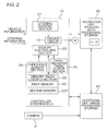
- FIG.2 is a block diagram for illustrating an electrical arrangement of the controller 10 and a connection relation of a navigation unit 30 and an additional unit 40 which are electrically connected to the controller 10.
- the controller 10 includes a microcomputer and memories as well as a driving circuit 15 for supplying an electric power from an on-board battery to the electric motor M.
- a plurality of functional processing units implemented in predetermined programs executed by means of the microcomputer and memories of the controller 10 are represented by blocks, which include: a steering control section 21 for controlling the electric motor M according to the assist mode; a memory (data logging section) 22 for logging necessary data for operation as a drive recorder; a memory controlling section 23 for controlling the memory 22; a threshold judging section 24 and a data-transfer timing output section 25 for applying a trigger signal to the memory controlling section 23.
- the memory 22 is segmented into a first memory 221 for receiving information and a second memory 222 for storing information, which will be described hereinlater.
- the detection signals from the vehicle speed sensor 12, acceleration sensor 13 and yaw rate sensor 14 are applied to the controller 10 as vehicle information.
- the steering angle detected by the steering angle sensor 17 and the steering torque detected by the torque sensor 11 are applied to the controller 10 as steering information.
- the memory controlling section 23, threshold judging section 24, data-transfer timing output section 25 and memory 22 execute predetermined functions of the drive recorder based on these vehicle information items and steering information items.
- the controller 10 is also electrically connected with the navigation unit 30 (navigation system) and the additional unit 40 which are set in the vehicle.
- the navigation unit 30 and the additional unit 40 are also electrically connected with each other. These connection relations may be established by an in-vehicle LAN (Local Area Network), for example.
- LAN Local Area Network
- the navigation unit 30 is installed in the vehicle.
- the navigation unit is operative to detect the present position of the vehicle based on signals and the like inputted thereto via a GPS (Global Positioning System) antenna and the like, and to display map information and the present position of the vehicle on a display screen.
- the navigation unit 30 normally includes a large memory device such as a hard disk.
- the additional unit 40 is operative to process image data, for example, on scenes out the front of the vehicle captured by an in-vehicle camera 41 and to store the processed data as needed.
- the additional unit 40 and the in-vehicle camera 41 can be options for the vehicle.
- the additional unit 40 is electrically connected to the controller 10 and the navigation unit 30, so as to be capable of sending/receiving signals or information thereto/therefrom.
- the feature of the embodiment resides in that the controller (steering ECU) 10 is imparted with basic functions of the drive recorder and that the controller 10 functioning as the drive recorder operates to transfer the logged data to the large memory of hard disk in the navigation unit 30 at a predetermined timing.
- the navigation unit 30 detects the vehicle position and stores the vehicle position information in the hard disk thereof, while associating the vehicle position information with the vehicle information and steering information logged by the controller 10.
- Yet another feature of the embodiment is that not only the above vehicle information, steering information and position information but also the image data captured by the in-vehicle camera 41 can be stored in a case where the additional unit 40 and the in-vehicle camera 41 are retro-fitted.
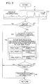
- a control operation by the controller 10 shown in FIG.2 is described as below according to a flow chart shown in FIG.3.
- FIG.3 is a flow chart showing a control operation executed by the controller 10 and the contents of drive-recorder operations executed by the memory controlling section 23, the threshold judging section 24, the data-transfer timing output section 25 and the memory 22.
- the controller 10 is supplied with the vehicle information (vehicle acceleration, yaw rate, vehicle speed and the like) and the steering information (steering angle, steering torque and the like).
- vehicle information vehicle acceleration, yaw rate, vehicle speed and the like
- steering information steering angle, steering torque and the like
- a variety of information items so supplied are stored in a first memory 221 for receiving information, which is constituted by a buffer memory or the like (Step S1).
- the first memory 221 is a memory of a type such as FIFO memory, which stores the information pieces in the input order until it is filled and which sequentially deletes the information pieces by causing the information pieces to overflow from the memory region in the chronological order, earliest piece first.
- the threshold judging section 24 observes the variations of the vehicle acceleration included in the stored information items.
- the threshold judging section 24 determines whether the vehicle acceleration exceeds a predetermined threshold or not (Step S2). If the threshold is exceeded, the threshold judging section 24 applies a data storing command to the memory controlling section 23 (Step S3).
- the memory controlling section 23 stores information recorded, for example, in a tens-second period before and after a time point t i at which the data storing command is applied thereto (the vehicle acceleration exceeds the predetermined threshold), while associating the information with the time point t i , from the information pieces stored in the first memory 221.
- the information piece recorded in the tens-second period before and after the time point t i (the length of time period is optional and a matter of design) is transferred to the second memory 222 for storing information, which stores the information piece in association with the time point t i (Step S4).
- Step S3 The data storing command outputted in Step S3 is also applied to the navigation unit 30 and the additional unit 40 at the same time, as will be described hereinlater.
- Steps S1 to S4 are continuously carried on, whereby plural data items recorded in the respective time periods before and after the respective time points at which the vehicle acceleration exceeds the predetermined threshold are stored in the second memory 222 in association with the time points. For instance, an information item 1 associated with a time point t1, an information item 2 associated with a time point t2, ... an information item i associated with a time point t i may be stored.
- the data-transfer timing output section 25 determines whether it is a predetermined timing for data transfer or not (Step S5) .
- the predetermined timing means, for example, time when the vehicle is parked with the motor idling, or time occurring at the predetermined time intervals at which the data transfer is smoothly carried out (when the controller 10 has such a low control load as to be able to transfer the data).
- the memory controlling section 23 transfers the information stored in the second memory 222 or stored in Step S4 to the hard disk of the navigation unit 30 electrically connected thereto by means of an in-vehicle LAN or the like (Step S6).
- the accumulated information items are transferred to a larger storage unit (hard disk) of the navigation unit 30.
- the memory 22 of the controller 10, particularly the second memory 222 need not have a large capacity.
- the existing controller (steering ECU) 10 may be used as the drive recorder for favorably recording the information.
- the threshold judging section 24 triggers the storing operation at the time point t i of a moment when the vehicle acceleration exceeds the predetermined threshold, and the vehicle information including the vehicle acceleration, yaw rate, vehicle speed and the like, and the steering information including the steering angle, steering torque and the like are stored for a tens-second period before and after the time point t i .
- the vehicle abruptly changes its behavior, particularly the vehicle acceleration changes quickly, in a case where the vehicle is involved in an accident. Therefore, according to the embodiment, whether the vehicle acceleration exceeds the predetermined threshold or not is used as a trigger criterion for the operation of storing the information.
- the operation of storing the information is carried out. That is, all the information items stored in the second memory 222 are not related to the accident. Rather, the most (for example, 90% or more) of the information items may be unrelated to the vehicle accident.
- the changes of the yaw rate, vehicle speed, steering angle, steering torque and the like recorded in the tens-second period before and after the vehicle acceleration exceeding the predetermined threshold may provide useful drive recorder information which may be analyzed to contribute to safe driving.
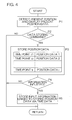
- FIG. 4 is a flow chart showing the steps of a control operation performed by the navigation unit 30.
- the memory controlling section 23 transfers the logged time points and information items from the second memory 222 to the navigation unit 30. Receiving the data thus transferred, the navigation unit 30 performs the control operation shown in FIG.4.
- the navigation unit 30 performs a normal operation to detect the present position of the vehicle based on a GPS signal and the like and displays the present vehicle position data on a map (Step P1).
- the navigation unit 30 determines whether the data storing command is outputted or not (Step P2). As described above, the data storing command is supplied from the threshold judging section 24 of the controller 10. At the moment when the vehicle acceleration exceeds the predetermined threshold, the threshold judging section 24 outputs the data storing command to the memory controlling section 23 and to the navigation unit 30 as well.
- the navigation unit 30 stores the position data recorded at the time point t i of interest in the memory.
- the position data may be numerical data representing degrees of latitude and longitude or values on coordinate axes, or image data indicating the vehicle position on the map data.
- Step P3 Every time the data storing command is outputted, the position data is stored as associated with the time point at which the data storing command is supplied.
- Step P4 when the information is transferred from the controller 10 (the operation of transferring the information is accomplished) (YES in Step P4), the navigation unit 30 links the input information to the time data, thereby associating the input information thus transferred with the position data stored in Step P3 and then storing the resultant data/information at the hard disk or the like (Step P5) .
- the vehicle information items, the steering information items and the vehicle position data recorded in the tens-second period before and after the time point that the vehicle acceleration exceeds the predetermined threshold may be stored in the navigation unit 30 as the drive recorder information.
- the navigation unit 30 is generally installed in the interior of the vehicle at place easy for a user to manipulate, in order to permit the user to insert a disk storing an electronic map or to perform other necessary operations.
- the controller (steering ECU) 10 is incorporated in the power steering apparatus and hence, is normally disposed at place un-accessible to the user and hard for the user to manipulate the controller.
- the constitution is made such that the drive recorder information is transferred to the navigation unit 30 and stored in the hard disk of the navigation unit 30.
- This constitution offers an advantage that the drive recorder information may be retrieved from the navigation unit 30.
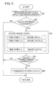
- FIG.5 is a flow chart showing the steps of a control operation performed by the additional unit 40 shown in FIG.2.
- the additional unit 40 normally processes the image data supplied from the in-vehicle camera 41 and displays the image data on the display screen or the like as needed (Step Q1).
- the additional unit 40 stores the image data recorded at the moment (time point t i ) of receiving the data storing command, while linking the image data to the time point t i (Step Q3).
- the additional unit 40 sequentially stores the image data pieces recorded at individual moments when the vehicle acceleration exceeds the predetermined threshold.
- the additional unit 40 may be adapted to store not only the image data piece recorded at the time point t i , but also the image data pieces recorded in a certain period (tens of seconds) before and after the time point t i .
- the additional unit 40 transfers the time data and the image data stored therein to the navigation unit 30 (Step Q5) .
- the data transferring command (command to transfer data) in Step Q4 is applied from the data-transfer timing output section 25, for example.
- the additional unit 40 transfers the stored image data to the navigation unit 30, which links the transferred image data to the position data and the inputted information based on the time data and then, stores the resultant data/information.
- the information related to the change of the vehicle acceleration, the change of the vehicle speed, the change of the yaw rate, the change of the steering angle, the change of the steering torque and the like recorded in the tens-second period before and after the moment when the vehicle speed exceeds the predetermined threshold is associated with the vehicle position at the moment of interest and with the image data on outside circumstances captured by the in-vehicle camera at the moment of interest, and the information and data so associated are stored in the navigation unit 30.
- the information and data stored in the navigation unit 30 can be effectively used as the drive recorder information.
- the above embodiment has been described by use of an example where all the information and data are eventually stored in the navigation unit 30.
- the additional unit 40 includes a large memory such as a hard disk, however, an alternative constitution may be made such that the information and data are stored in the additional unit 40.
- the vehicle information, steering information and vehicle position information may be stored in the memory 22 of the controller 10 rather than in the navigation unit 30.
- the signal indicative of the vehicle acceleration exceeding the predetermined threshold is used as the trigger signal for storing the information.
- any other signal may be used to trigger the operation of storing the information.
- the operation of storing the information may be triggered by a signal indicating that the change of the vehicle speed exceeds a predetermined threshold, that the change of the yaw rate exceeds a predetermined threshold, that the change of the steering angle exceeds a predetermined threshold, that the change of the steering torque exceeds a predetermined threshold, or such.
- a low-cost and versatile drive recorder can be constructed by utilizing the existing vehicle electronic control unit such as the steering ECU, and imparting the drive recorder functions to the steering ECU.
- the constitution is made such that the basic functions of the drive recorder are imparted to the existing vehicle electronic control unit (ECU), from which the information stored therein is eventually transferred to the navigation unit 30 or the additional unit 40, from which the information can be retrieved.
- ECU vehicle electronic control unit
- the constitution can facilitate the retrieval of the information and can provide the implementation of user-friendly drive recorder functions.
Landscapes
- Physics & Mathematics (AREA)
- General Physics & Mathematics (AREA)
- Time Recorders, Dirve Recorders, Access Control (AREA)
- Alarm Systems (AREA)
- Signal Processing For Digital Recording And Reproducing (AREA)
- Traffic Control Systems (AREA)
- Navigation (AREA)
Abstract
An in-vehicle controller of the invention is a so-called drive recorder. The drive recorder is incorporated in a steering ECU (controller) 10. For this purpose, the controller 10 is provided with function implementation units which includes a memory 22 as a data logging section, a memory controlling section 23, a threshold judging section 24 and a data-transfer timing output section 25. Vehicle information and steering information are stored in a first memory 221 in chronological order. A second memory 222 logs data recorded in a tens-second period before and after a moment when vehicle acceleration exceeds a predetermined threshold. The information logged by the second memory 222 is transferred to a hard disk of a navigation unit 30 in a predetermined timing.
Description
- The present invention relates to an in-vehicle controller which utilizes an existing electronic control unit (ECU) in a vehicle, in particular a steering ECU or brake ECU, for implementing functions of a so-called drive recorder.
- In order to deal with a motor vehicle accident and to reduce the number of motor vehicle accidents, the drive recorder has been developed with an aim at widespread use of the drive recorder in business-purpose vehicles such as taxies and trucking vehicles.
- One example of the drive recorder is disclosed in
Japanese Unexamined Patent Publication No.2003-87778 - Although the drive recorders heretofore proposed in the art provide an effective tool to deal with a motor vehicle accident or to reduce the number of motor vehicle accidents, the following problem exists. The drive recorder is developed as a special-purpose device and is usually option for a vehicle. Hence, the drive recorder is costly.
- More specifically, the drive recorder is constituted as a device which includes an image-pickup super-wide-angle lens, a CPU and various storage units and which is independent from normal on-board devices. Further, the drive recorder must be so designed and positioned as to ensure a recording operation and the like during a period before and after the occurrence of an accident if the vehicle should be involved in the accident. Naturally, the drive recorder is a costly device.
- The expensive drive recorder is useless until the vehicle encounters an accident. Accordingly, the drive recorders have not yet to be popularized.
- In view of the foregoing, it is a primary object of the invention to provide an in-vehicle controller having a drive recorder functions, which is less costly and excellent in performance and can contribute to the increase of penetration rate of the drive recorder.
- It is another object of the invention to provide an in-vehicle controller adapted to incorporate a drive recorder functions in the existing vehicle controller, such as a steering ECU.
- It is still another object of the invention to provide an in-vehicle controller for use in a vehicle equipped with a navigation unit, which has a drive recorder functions.
Above objects are achieved by the construction ofclaim 1 of the present invention. - According to the
present claim 1 invention, vehicle information and steering information crucial for the drive recorder are first stored in a storage unit installed in the in-vehicle controller. Subsequently, the vehicle information and steering information stored in the storage unit are transferred to the navigation unit in a predetermined timing such as when the vehicle is stopped with the motor idling, or at predetermined time intervals. The navigation unit normally has a large memory such as a, hard disk therein. Hence, these information items can be favorably stored in the navigation unit without encountering a problem that an available memory region is insufficient for the inputted vehicle information and steering information. - Since the navigation unit is often disposed at place easy for a user to manipulate, the user may easily retrieve the information from the navigation unit.
- Accordingly, the
present claim 1 invention can provide the in-vehicle controller which is less costly and features user-friendly drive recorder functions.
The present invention may comprise a first storage unit (221) and a second storage unit (222) as the storage unit (22) as the construction ofclaim 2. - According to the
claim 2 invention, information recorded at a crucial moment for the drive recorder can be efficiently stored at a second storage unit. The crucial information may be, for example, information recorded in a predetermined period before and after a moment when the behavior of the vehicle is significantly changed like when the acceleration of the vehicle exceeds a predetermined threshold. The information stored in the second storage unit is associated with the time point of the moment of exceeding the threshold, thus offering an advantage of easy linking to other information items as will be described hereinlater.
Asclaim 3, the present invention may further comprise: an acquisition unit arranged to acquire vehicle position information detected by the navigation unit; and a position information writing control unit (P3) arranged to write vehicle position information which acquires from the acquisition unit into the storage unit (22) or the navigation unit (30), the vehicle position information indicates at the moment of exceeding the threshold accompany with the vehicle information and steering information. - According to the
claim 3 invention, vehicle position information detected by the navigation unit can also be stored as associated with the vehicle information and steering information. This results in even further enhanced drive recorder functions.
According toclaim 4, the present invention may further comprise: a camera unit (41) arranged to get at least an image of outside circumstances of the vehicle; and an image data writing control unit (40) arranged to write the image data got by the camera unit (41) into the storage unit (22) or the navigation unit (30), the image data shows the image at the moment of exceeding the threshold accompany with the vehicle information and the steering information. - The constitution of the
claim 4 invention may further comprise a camera unit for acquiring at least an image of outside circumstances of the vehicle, and an image data writing control unit for storing the image data in the storage unit or the navigation unit. This permits the image data to be associated with the vehicle position information and the steering information, and the image data recorded at the moment of interest to be stored. Thus, the drive recorder functions can be enhanced even further. -
- FIG. 1 is a conceptual diagram for illustrating an arrangement of an electric power steering apparatus equipped with a steering ECU, in which an in-vehicle controller according to an embodiment of the invention is implemented;
- FIG.2 is a block diagram for illustrating an electrical arrangement of a
controller 10 and a connection relation of anavigation unit 30 and anadditional unit 40 which are electrically connected to thecontroller 10; - FIG.3 is a flow chart showing a control operation executed by the
controller 10 and the contents of drive-recorder operations executed by amemory controlling section 23, athreshold judging section 24, a data-transfertiming output section 25 and amemory 22; - FIG.4 is a flow chart showing the steps of a control operation executed by the
navigation unit 30; and - FIG.5 is a flow chart showing the steps of a control operation executed by the
additional unit 40. - The preferred embodiments of the present invention will hereinbelow be described in details with reference to the accompanying drawings.
- An in-vehicle controller according to an embodiment of the invention is implemented in a steering ECU (Electronic Control Unit). FIG.1 is a conceptual diagram for illustrating an arrangement of an electric power steering apparatus including the steering ECU. The electric power steering apparatus is designed to transmit a torque generated by an electric motor M as a steering actuator to a
steering mechanism 1 for steering steerable vehicle wheels W (such as front-right and front-left vehicle wheels) of a vehicle. Thesteering mechanism 1 is of a rack and pinion type which includes: arack shaft 2 extending transversely in the vehicle; and apinion 3 meshed with a rack of therack shaft 2. Thepinion 3 is coupled to one end of asteering shaft 4, the other end of which is coupled to asteering wheel 5. Therefore, when thesteering wheel 5 is operatively rotated, the rotational motion of thesteering wheel 5 is transmitted to therack shaft 2 via thesteering shaft 4 and thepinion 3, to be converted to axial movement of therack shaft 2. - The opposite ends of the
rack shaft 2 are connected with one ends of a pair oftie rods 6, respectively. The other ends of the pair oftie rods 6 are connected with one ends of a pair ofknuckle arms 7, respectively. The pair ofknuckle arms 7 are each pivotally supported about each of a pair ofking pins 8 and are connected to the pair of steerable road wheels W respectively. According to this arrangement, the axial movement of therack shaft 2 causes theknuckle arms 7 to pivot about theking pins 8, whereby the steerable road wheels W are steered. - A controller (also referred to as "steering ECU") 10 for controlling the electric motor M is provided for the purpose of applying a proper steering force to the
steering mechanism 1. Thecontroller 10 is adapted to receive: an output signal from atorque sensor 11 for detecting a steering torque applied to thesteering wheel 5; an output signal from asteering angle sensor 17 for detecting an steering angle of thesteering wheel 5 by detecting a rotation angle of thesteering shaft 4; an output signal from avehicle speed sensor 12 for detecting a speed of the vehicle equipped with the electric power steering apparatus; an output signal from anacceleration sensor 13 for detecting an acceleration of the vehicle equipped with the electric power steering apparatus; and an output signal from ayaw rate sensor 14 for detecting a yaw rate of the vehicle equipped with the electric power steering apparatus. Thecontroller 10 may also be adapted to receive an operation signal from a direction indicator associated with thesteering wheel 5. - The
controller 10 normally controls the electric motor M according to an assist mode. The assist mode means a control mode wherein the electric motor M is controlled based on the steering torque detected by thetorque sensor 11 and the vehicle speed detected by thevehicle speed sensor 12 to generate a steering assist force for assisting a driver in steering operation. - FIG.2 is a block diagram for illustrating an electrical arrangement of the
controller 10 and a connection relation of anavigation unit 30 and anadditional unit 40 which are electrically connected to thecontroller 10. Thecontroller 10 includes a microcomputer and memories as well as adriving circuit 15 for supplying an electric power from an on-board battery to the electric motor M. - A plurality of functional processing units implemented in predetermined programs executed by means of the microcomputer and memories of the
controller 10 are represented by blocks, which include: asteering control section 21 for controlling the electric motor M according to the assist mode; a memory (data logging section) 22 for logging necessary data for operation as a drive recorder; amemory controlling section 23 for controlling thememory 22; athreshold judging section 24 and a data-transfertiming output section 25 for applying a trigger signal to thememory controlling section 23. Thememory 22 is segmented into afirst memory 221 for receiving information and asecond memory 222 for storing information, which will be described hereinlater. - As described above, the detection signals from the
vehicle speed sensor 12,acceleration sensor 13 andyaw rate sensor 14 are applied to thecontroller 10 as vehicle information. On the other hand, the steering angle detected by thesteering angle sensor 17 and the steering torque detected by thetorque sensor 11 are applied to thecontroller 10 as steering information. In thecontroller 10, thememory controlling section 23,threshold judging section 24, data-transfertiming output section 25 andmemory 22 execute predetermined functions of the drive recorder based on these vehicle information items and steering information items. - The
controller 10 is also electrically connected with the navigation unit 30 (navigation system) and theadditional unit 40 which are set in the vehicle. Thenavigation unit 30 and theadditional unit 40 are also electrically connected with each other. These connection relations may be established by an in-vehicle LAN (Local Area Network), for example. - The
navigation unit 30 is installed in the vehicle. The navigation unit is operative to detect the present position of the vehicle based on signals and the like inputted thereto via a GPS (Global Positioning System) antenna and the like, and to display map information and the present position of the vehicle on a display screen. Thenavigation unit 30 normally includes a large memory device such as a hard disk. - The
additional unit 40 is operative to process image data, for example, on scenes out the front of the vehicle captured by an in-vehicle camera 41 and to store the processed data as needed. Theadditional unit 40 and the in-vehicle camera 41 can be options for the vehicle. Theadditional unit 40 is electrically connected to thecontroller 10 and thenavigation unit 30, so as to be capable of sending/receiving signals or information thereto/therefrom. - The feature of the embodiment resides in that the controller (steering ECU) 10 is imparted with basic functions of the drive recorder and that the
controller 10 functioning as the drive recorder operates to transfer the logged data to the large memory of hard disk in thenavigation unit 30 at a predetermined timing. Another feature of the embodiment is that thenavigation unit 30 detects the vehicle position and stores the vehicle position information in the hard disk thereof, while associating the vehicle position information with the vehicle information and steering information logged by thecontroller 10. - Yet another feature of the embodiment is that not only the above vehicle information, steering information and position information but also the image data captured by the in-
vehicle camera 41 can be stored in a case where theadditional unit 40 and the in-vehicle camera 41 are retro-fitted. - A control operation by the
controller 10 shown in FIG.2 is described as below according to a flow chart shown in FIG.3. - FIG.3 is a flow chart showing a control operation executed by the
controller 10 and the contents of drive-recorder operations executed by thememory controlling section 23, thethreshold judging section 24, the data-transfertiming output section 25 and thememory 22. - The
controller 10 is supplied with the vehicle information (vehicle acceleration, yaw rate, vehicle speed and the like) and the steering information (steering angle, steering torque and the like). A variety of information items so supplied are stored in afirst memory 221 for receiving information, which is constituted by a buffer memory or the like (Step S1). Thefirst memory 221 is a memory of a type such as FIFO memory, which stores the information pieces in the input order until it is filled and which sequentially deletes the information pieces by causing the information pieces to overflow from the memory region in the chronological order, earliest piece first. - In parallel with the
first memory 221 storing the information items, thethreshold judging section 24 observes the variations of the vehicle acceleration included in the stored information items. Thethreshold judging section 24 determines whether the vehicle acceleration exceeds a predetermined threshold or not (Step S2). If the threshold is exceeded, thethreshold judging section 24 applies a data storing command to the memory controlling section 23 (Step S3). Receiving the data storing command, thememory controlling section 23 stores information recorded, for example, in a tens-second period before and after a time point ti at which the data storing command is applied thereto (the vehicle acceleration exceeds the predetermined threshold), while associating the information with the time point ti, from the information pieces stored in thefirst memory 221. Specifically, out of the information pieces temporarily stored in thefirst memory 221, the information piece recorded in the tens-second period before and after the time point ti (the length of time period is optional and a matter of design) is transferred to thesecond memory 222 for storing information, which stores the information piece in association with the time point ti (Step S4). - The data storing command outputted in Step S3 is also applied to the
navigation unit 30 and theadditional unit 40 at the same time, as will be described hereinlater. - The operations of Steps S1 to S4 are continuously carried on, whereby plural data items recorded in the respective time periods before and after the respective time points at which the vehicle acceleration exceeds the predetermined threshold are stored in the
second memory 222 in association with the time points. For instance, aninformation item 1 associated with a time point t1, aninformation item 2 associated with a time point t2, ... an information item i associated with a time point ti may be stored. - On the other hand, the data-transfer
timing output section 25 determines whether it is a predetermined timing for data transfer or not (Step S5) . The predetermined timing means, for example, time when the vehicle is parked with the motor idling, or time occurring at the predetermined time intervals at which the data transfer is smoothly carried out (when thecontroller 10 has such a low control load as to be able to transfer the data). When the data-transfertiming output section 25 outputs a signal indicating that it is the predetermined timing, thememory controlling section 23 transfers the information stored in thesecond memory 222 or stored in Step S4 to the hard disk of thenavigation unit 30 electrically connected thereto by means of an in-vehicle LAN or the like (Step S6). - When the information items stored in association with the time points are thus accumulated in the
second memory 222 for logging which is installed in thecontroller 10, the accumulated information items are transferred to a larger storage unit (hard disk) of thenavigation unit 30. Hence, thememory 22 of thecontroller 10, particularly thesecond memory 222, need not have a large capacity. The existing controller (steering ECU) 10 may be used as the drive recorder for favorably recording the information. - According to the embodiment, the
threshold judging section 24 triggers the storing operation at the time point ti of a moment when the vehicle acceleration exceeds the predetermined threshold, and the vehicle information including the vehicle acceleration, yaw rate, vehicle speed and the like, and the steering information including the steering angle, steering torque and the like are stored for a tens-second period before and after the time point ti. - In general, the vehicle abruptly changes its behavior, particularly the vehicle acceleration changes quickly, in a case where the vehicle is involved in an accident. Therefore, according to the embodiment, whether the vehicle acceleration exceeds the predetermined threshold or not is used as a trigger criterion for the operation of storing the information. In a case where the driver makes a hard stop, as well, there is naturally a great change of the vehicle acceleration and hence, the operation of storing the information is carried out. That is, all the information items stored in the
second memory 222 are not related to the accident. Rather, the most (for example, 90% or more) of the information items may be unrelated to the vehicle accident. However, even though these information items are unrelated to the accident, the changes of the yaw rate, vehicle speed, steering angle, steering torque and the like recorded in the tens-second period before and after the vehicle acceleration exceeding the predetermined threshold may provide useful drive recorder information which may be analyzed to contribute to safe driving. - FIG. 4 is a flow chart showing the steps of a control operation performed by the
navigation unit 30. As described with reference to FIG.3, when the data-transfertiming output section 25 determines that it is the predetermined time to transfer the information, thememory controlling section 23 transfers the logged time points and information items from thesecond memory 222 to thenavigation unit 30. Receiving the data thus transferred, thenavigation unit 30 performs the control operation shown in FIG.4. - The
navigation unit 30 performs a normal operation to detect the present position of the vehicle based on a GPS signal and the like and displays the present vehicle position data on a map (Step P1). - In parallel with the detection of the present position and the display control operation, the
navigation unit 30 determines whether the data storing command is outputted or not (Step P2). As described above, the data storing command is supplied from thethreshold judging section 24 of thecontroller 10. At the moment when the vehicle acceleration exceeds the predetermined threshold, thethreshold judging section 24 outputs the data storing command to thememory controlling section 23 and to thenavigation unit 30 as well. - . In response to the data storing command so supplied, the
navigation unit 30 stores the position data recorded at the time point ti of interest in the memory. The position data may be numerical data representing degrees of latitude and longitude or values on coordinate axes, or image data indicating the vehicle position on the map data. - Every time the data storing command is outputted, the position data is stored as associated with the time point at which the data storing command is supplied (Step P3).
- Subsequently, when the information is transferred from the controller 10 (the operation of transferring the information is accomplished) (YES in Step P4), the
navigation unit 30 links the input information to the time data, thereby associating the input information thus transferred with the position data stored in Step P3 and then storing the resultant data/information at the hard disk or the like (Step P5) . - Accordingly, when the vehicle acceleration exceeds the predetermined threshold, the vehicle information items, the steering information items and the vehicle position data recorded in the tens-second period before and after the time point that the vehicle acceleration exceeds the predetermined threshold may be stored in the
navigation unit 30 as the drive recorder information. - By the way, the
navigation unit 30 is generally installed in the interior of the vehicle at place easy for a user to manipulate, in order to permit the user to insert a disk storing an electronic map or to perform other necessary operations. - On the other hand, the controller (steering ECU) 10 is incorporated in the power steering apparatus and hence, is normally disposed at place un-accessible to the user and hard for the user to manipulate the controller.
- Therefore, the constitution is made such that the drive recorder information is transferred to the
navigation unit 30 and stored in the hard disk of thenavigation unit 30. This constitution offers an advantage that the drive recorder information may be retrieved from thenavigation unit 30. - FIG.5 is a flow chart showing the steps of a control operation performed by the
additional unit 40 shown in FIG.2. Theadditional unit 40 normally processes the image data supplied from the in-vehicle camera 41 and displays the image data on the display screen or the like as needed (Step Q1). - Receiving the data storing command from the
threshold judging section 24 of the controller 10 (YES in Step Q2), theadditional unit 40 stores the image data recorded at the moment (time point ti) of receiving the data storing command, while linking the image data to the time point ti (Step Q3). - Specifically, the
additional unit 40 sequentially stores the image data pieces recorded at individual moments when the vehicle acceleration exceeds the predetermined threshold. - In a case where the
additional unit 40 has a large memory, theadditional unit 40 may be adapted to store not only the image data piece recorded at the time point ti, but also the image data pieces recorded in a certain period (tens of seconds) before and after the time point ti. - Receiving the data transferring command (command to transfer the data) (YES in Step Q4), the
additional unit 40 transfers the time data and the image data stored therein to the navigation unit 30 (Step Q5) . - The data transferring command (command to transfer data) in Step Q4 is applied from the data-transfer
timing output section 25, for example. In response to the data transferring command, theadditional unit 40 transfers the stored image data to thenavigation unit 30, which links the transferred image data to the position data and the inputted information based on the time data and then, stores the resultant data/information. - Thus, the information related to the change of the vehicle acceleration, the change of the vehicle speed, the change of the yaw rate, the change of the steering angle, the change of the steering torque and the like recorded in the tens-second period before and after the moment when the vehicle speed exceeds the predetermined threshold is associated with the vehicle position at the moment of interest and with the image data on outside circumstances captured by the in-vehicle camera at the moment of interest, and the information and data so associated are stored in the
navigation unit 30. - Therefore, the information and data stored in the
navigation unit 30 can be effectively used as the drive recorder information. - The above embodiment has been described by use of an example where all the information and data are eventually stored in the
navigation unit 30. In a case where theadditional unit 40 includes a large memory such as a hard disk, however, an alternative constitution may be made such that the information and data are stored in theadditional unit 40. - In a case where the
memory 22 of thecontroller 10 has a large capacity, the vehicle information, steering information and vehicle position information may be stored in thememory 22 of thecontroller 10 rather than in thenavigation unit 30. - In the foregoing embodiment, the signal indicative of the vehicle acceleration exceeding the predetermined threshold is used as the trigger signal for storing the information. However, any other signal may be used to trigger the operation of storing the information. For instance, the operation of storing the information may be triggered by a signal indicating that the change of the vehicle speed exceeds a predetermined threshold, that the change of the yaw rate exceeds a predetermined threshold, that the change of the steering angle exceeds a predetermined threshold, that the change of the steering torque exceeds a predetermined threshold, or such.
- According to the invention, a low-cost and versatile drive recorder can be constructed by utilizing the existing vehicle electronic control unit such as the steering ECU, and imparting the drive recorder functions to the steering ECU.
- While the foregoing embodiments illustrate the example where the steering ECU is utilized as the drive recorder, an engine ECU or the like may be imparted with such functions.
- In either case, the constitution is made such that the basic functions of the drive recorder are imparted to the existing vehicle electronic control unit (ECU), from which the information stored therein is eventually transferred to the
navigation unit 30 or theadditional unit 40, from which the information can be retrieved. The constitution can facilitate the retrieval of the information and can provide the implementation of user-friendly drive recorder functions. - The invention is not limited to the foregoing embodiments, and various changes or modifications may be made thereto within the scope of the appended claims.
- The present application corresponds to Patent Application No.2006-224998 filed with Japanese Patent Office on August 22, 2006, the whole disclosure of which is incorporated herein by reference.
Claims (4)
- An in-vehicle controller (10) for use in a vehicle equipped with a navigation unit (30), comprising:a storage unit (22) arranged to store vehicle information and steering information in chronological order; anda writing control unit (23) arranged to write the vehicle information and steering information stored in the storage unit (22) to the navigation unit (30) in a predetermined timing.
- An in-vehicle controller (10) according to Claim 1, wherein the storage unit (22) includes:a first storage unit (221) arranged to store the inputted vehicle information and steering information in an input order; anda second storage unit (222) arranged to store some information stored in the first storage unit (221), which responds to that a predetermined information item of the inputted vehicle information exceeds a predetermined threshold, in a predetermined period before and after the moment of exceeding the threshold with a time point of the moment of exceeding the threshold.
- An in-vehicle controller (10) according to Claim 2, further comprising:an acquisition unit arranged to acquire vehicle position information detected by the navigation unit; anda position information writing control unit (P3) arranged to write vehicle position information which acquires from the acquisition unit into the storage unit (22) or the navigation unit (30), the vehicle position information indicates at the moment of exceeding the threshold accompany with the vehicle information and steering information.
- An in-vehicle controller (10) according to Claims 2 or 3, further comprising:a camera unit (41) arranged to get at least an image of outside circumstances of the vehicle; andan image data writing control unit (40) arranged to write the image data got by the camera unit (41) into the storage unit (22) or the navigation unit (30), the image data shows the image at the moment of exceeding the threshold accompany with the vehicle information and the steering information.
Applications Claiming Priority (1)
| Application Number | Priority Date | Filing Date | Title |
|---|---|---|---|
| JP2006224998A JP5141941B2 (en) | 2006-08-22 | 2006-08-22 | In-vehicle control device |
Publications (1)
| Publication Number | Publication Date |
|---|---|
| EP1892673A1 true EP1892673A1 (en) | 2008-02-27 |
Family
ID=38859049
Family Applications (1)
| Application Number | Title | Priority Date | Filing Date |
|---|---|---|---|
| EP07015668A Withdrawn EP1892673A1 (en) | 2006-08-22 | 2007-08-09 | Drive recorder |
Country Status (3)
| Country | Link |
|---|---|
| US (1) | US20080051988A1 (en) |
| EP (1) | EP1892673A1 (en) |
| JP (1) | JP5141941B2 (en) |
Cited By (2)
| Publication number | Priority date | Publication date | Assignee | Title |
|---|---|---|---|---|
| CN103065371A (en) * | 2012-12-03 | 2013-04-24 | 深圳市元征科技股份有限公司 | Traffic accident responsibility definition method |
| CN108701379A (en) * | 2017-01-31 | 2018-10-23 | 日本精工株式会社 | Driving information recording apparatus and electric power-assisted steering apparatus with the driving information recording apparatus |
Families Citing this family (10)
| Publication number | Priority date | Publication date | Assignee | Title |
|---|---|---|---|---|
| JPH0757912A (en) * | 1993-08-13 | 1995-03-03 | Sumitomo Metal Ind Ltd | High corrosion resistance sintered permanent magnet |
| US8386730B2 (en) * | 2007-09-11 | 2013-02-26 | Nec Corporation | Data logger, data saving method and program |
| JP5332240B2 (en) * | 2008-03-11 | 2013-11-06 | 富士通株式会社 | Drive recorder and computer program |
| JPWO2011013839A1 (en) * | 2009-07-28 | 2013-01-10 | 愼 早川 | Speed display device for vehicle |
| PT2312536E (en) * | 2009-10-15 | 2013-10-10 | Kapsch Trafficcom Ag | Vehicle device for a street toll system |
| JP5471871B2 (en) * | 2010-06-17 | 2014-04-16 | 株式会社デンソー | Vehicle information storage device |
| JP6470308B2 (en) * | 2014-11-19 | 2019-02-13 | エイディシーテクノロジー株式会社 | Automatic operation control device |
| JP6144737B2 (en) * | 2015-09-15 | 2017-06-07 | 富士通テン株式会社 | Drive recorder and image storage method |
| WO2019111336A1 (en) * | 2017-12-05 | 2019-06-13 | みなと観光バス株式会社 | Digital tachograph, and operation management system |
| US20250346294A1 (en) * | 2021-12-16 | 2025-11-13 | Nidec Corporation | Control device and lane keeping system |
Citations (2)
| Publication number | Priority date | Publication date | Assignee | Title |
|---|---|---|---|---|
| JP2003087778A (en) * | 2001-09-06 | 2003-03-20 | Suzuki Motor Corp | Drive recorder |
| JP2006151006A (en) * | 2004-11-25 | 2006-06-15 | Yamaha Corp | Drive recorder device |
Family Cites Families (8)
| Publication number | Priority date | Publication date | Assignee | Title |
|---|---|---|---|---|
| JP3132222B2 (en) * | 1993-03-05 | 2001-02-05 | 株式会社デンソー | Rear wheel steering device for four-wheel steering vehicle |
| JP2865239B2 (en) * | 1993-07-23 | 1999-03-08 | 矢崎総業株式会社 | Vehicle operation recording device |
| JPH09145402A (en) * | 1995-11-22 | 1997-06-06 | Matsushita Electric Ind Co Ltd | Navigation device |
| DE19640940A1 (en) * | 1996-10-04 | 1998-04-09 | Bosch Gmbh Robert | navigation system |
| JP3654047B2 (en) * | 1999-05-14 | 2005-06-02 | 日産自動車株式会社 | Vehicle status recording device |
| JP4394780B2 (en) * | 1999-10-08 | 2010-01-06 | クラリオン株式会社 | Mobile body information recording device |
| JP2003203285A (en) * | 2002-01-09 | 2003-07-18 | Mitsubishi Electric Corp | Status recording device |
| JP2004177328A (en) * | 2002-11-28 | 2004-06-24 | Matsushita Electric Ind Co Ltd | Navigation device |
-
2006
- 2006-08-22 JP JP2006224998A patent/JP5141941B2/en not_active Expired - Fee Related
-
2007
- 2007-08-09 EP EP07015668A patent/EP1892673A1/en not_active Withdrawn
- 2007-08-20 US US11/892,080 patent/US20080051988A1/en not_active Abandoned
Patent Citations (2)
| Publication number | Priority date | Publication date | Assignee | Title |
|---|---|---|---|---|
| JP2003087778A (en) * | 2001-09-06 | 2003-03-20 | Suzuki Motor Corp | Drive recorder |
| JP2006151006A (en) * | 2004-11-25 | 2006-06-15 | Yamaha Corp | Drive recorder device |
Cited By (5)
| Publication number | Priority date | Publication date | Assignee | Title |
|---|---|---|---|---|
| CN103065371A (en) * | 2012-12-03 | 2013-04-24 | 深圳市元征科技股份有限公司 | Traffic accident responsibility definition method |
| CN103065371B (en) * | 2012-12-03 | 2016-04-06 | 深圳市元征科技股份有限公司 | Traffic accident responsibility definition method |
| CN108701379A (en) * | 2017-01-31 | 2018-10-23 | 日本精工株式会社 | Driving information recording apparatus and electric power-assisted steering apparatus with the driving information recording apparatus |
| EP3382656A4 (en) * | 2017-01-31 | 2019-02-13 | NSK Ltd. | DRIVING INFORMATION RECORDING DEVICE AND ELECTRIC ASSISTED STEERING APPARATUS EQUIPPED WITH SAID DEVICE |
| US10621801B2 (en) | 2017-01-31 | 2020-04-14 | Nsk Ltd. | Drive information recording device and electric power steering device including the same |
Also Published As
| Publication number | Publication date |
|---|---|
| US20080051988A1 (en) | 2008-02-28 |
| JP2008052328A (en) | 2008-03-06 |
| JP5141941B2 (en) | 2013-02-13 |
Similar Documents
| Publication | Publication Date | Title |
|---|---|---|
| US20080051988A1 (en) | In-vehicle controller | |
| EP3745361B1 (en) | Vehicle recording control device, vehicle recording device, vehicle recording control method, and program | |
| JP4394780B2 (en) | Mobile body information recording device | |
| JP4971625B2 (en) | Driving support device and driving information calculation system | |
| JP2008186174A (en) | Running status recording device | |
| JP5920158B2 (en) | Image storage device for moving body | |
| JP6358414B1 (en) | Driving information recording apparatus and electric power steering apparatus provided with the same | |
| JP6451959B2 (en) | Operation management system | |
| JP6142338B2 (en) | Operation management system | |
| JPH07304473A (en) | Vehicle peripheral image data recording device | |
| CN110887677A (en) | Suspension system degradation detection | |
| US10262478B2 (en) | Vehicle-data recorder | |
| CN206209911U (en) | Driving recorder with intelligence | |
| WO1998024680A1 (en) | Method of reading record of running condition in travelling car | |
| KR20100057253A (en) | Image recording equipment around a vehicle | |
| JP2010250701A (en) | Drive recorder and setting program of drive recorder | |
| JP2023051997A (en) | On-vehicle video recording device and control method thereof | |
| JP2002170188A (en) | Operation situation recorder of vehicle | |
| KR101557280B1 (en) | Apparatus and Method of recording event based image data | |
| JP2021170337A (en) | Display control system, display control method and program | |
| JP7512847B2 (en) | Vehicle recording control device and vehicle recording control method | |
| JP5914121B2 (en) | Drive recorder | |
| JP2022030144A (en) | Device for detecting accident while being parked | |
| JP2024539580A5 (en) | ||
| JP2008225735A (en) | Operation status storage device |
Legal Events
| Date | Code | Title | Description |
|---|---|---|---|
| PUAI | Public reference made under article 153(3) epc to a published international application that has entered the european phase |
Free format text: ORIGINAL CODE: 0009012 |
|
| AK | Designated contracting states |
Kind code of ref document: A1 Designated state(s): AT BE BG CH CY CZ DE DK EE ES FI FR GB GR HU IE IS IT LI LT LU LV MC MT NL PL PT RO SE SI SK TR |
|
| AX | Request for extension of the european patent |
Extension state: AL BA HR MK YU |
|
| AKX | Designation fees paid | ||
| STAA | Information on the status of an ep patent application or granted ep patent |
Free format text: STATUS: THE APPLICATION IS DEEMED TO BE WITHDRAWN |
|
| 18D | Application deemed to be withdrawn |
Effective date: 20080828 |
|
| REG | Reference to a national code |
Ref country code: DE Ref legal event code: 8566 |