EP1892582A1 - Sheet Aligning Device and Image Forming Apparatus Including the Same - Google Patents
Sheet Aligning Device and Image Forming Apparatus Including the Same Download PDFInfo
- Publication number
- EP1892582A1 EP1892582A1 EP07114677A EP07114677A EP1892582A1 EP 1892582 A1 EP1892582 A1 EP 1892582A1 EP 07114677 A EP07114677 A EP 07114677A EP 07114677 A EP07114677 A EP 07114677A EP 1892582 A1 EP1892582 A1 EP 1892582A1
- Authority
- EP
- European Patent Office
- Prior art keywords
- sheet
- rollers
- pair
- conveying
- conveyance path
- Prior art date
- Legal status (The legal status is an assumption and is not a legal conclusion. Google has not performed a legal analysis and makes no representation as to the accuracy of the status listed.)
- Granted
Links
- 238000011144 upstream manufacturing Methods 0.000 claims abstract description 29
- 238000001514 detection method Methods 0.000 claims abstract description 9
- 238000012937 correction Methods 0.000 claims description 21
- 230000007246 mechanism Effects 0.000 description 32
- 238000012546 transfer Methods 0.000 description 12
- 210000000078 claw Anatomy 0.000 description 10
- 238000010586 diagram Methods 0.000 description 5
- 238000000926 separation method Methods 0.000 description 4
- 230000004907 flux Effects 0.000 description 3
- 238000000034 method Methods 0.000 description 3
- 230000003287 optical effect Effects 0.000 description 2
- 238000005452 bending Methods 0.000 description 1
- 239000000969 carrier Substances 0.000 description 1
- 239000003086 colorant Substances 0.000 description 1
- 230000007423 decrease Effects 0.000 description 1
- 238000013461 design Methods 0.000 description 1
- 238000011161 development Methods 0.000 description 1
- 230000000694 effects Effects 0.000 description 1
- 238000005516 engineering process Methods 0.000 description 1
- 238000004519 manufacturing process Methods 0.000 description 1
- 238000012986 modification Methods 0.000 description 1
- 230000004048 modification Effects 0.000 description 1
Images


Classifications
-
- B—PERFORMING OPERATIONS; TRANSPORTING
- B65—CONVEYING; PACKING; STORING; HANDLING THIN OR FILAMENTARY MATERIAL
- B65H—HANDLING THIN OR FILAMENTARY MATERIAL, e.g. SHEETS, WEBS, CABLES
- B65H9/00—Registering, e.g. orientating, articles; Devices therefor
- B65H9/002—Registering, e.g. orientating, articles; Devices therefor changing orientation of sheet by only controlling movement of the forwarding means, i.e. without the use of stop or register wall
-
- B—PERFORMING OPERATIONS; TRANSPORTING
- B65—CONVEYING; PACKING; STORING; HANDLING THIN OR FILAMENTARY MATERIAL
- B65H—HANDLING THIN OR FILAMENTARY MATERIAL, e.g. SHEETS, WEBS, CABLES
- B65H7/00—Controlling article feeding, separating, pile-advancing, or associated apparatus, to take account of incorrect feeding, absence of articles, or presence of faulty articles
- B65H7/02—Controlling article feeding, separating, pile-advancing, or associated apparatus, to take account of incorrect feeding, absence of articles, or presence of faulty articles by feelers or detectors
-
- B—PERFORMING OPERATIONS; TRANSPORTING
- B65—CONVEYING; PACKING; STORING; HANDLING THIN OR FILAMENTARY MATERIAL
- B65H—HANDLING THIN OR FILAMENTARY MATERIAL, e.g. SHEETS, WEBS, CABLES
- B65H7/00—Controlling article feeding, separating, pile-advancing, or associated apparatus, to take account of incorrect feeding, absence of articles, or presence of faulty articles
- B65H7/02—Controlling article feeding, separating, pile-advancing, or associated apparatus, to take account of incorrect feeding, absence of articles, or presence of faulty articles by feelers or detectors
- B65H7/06—Controlling article feeding, separating, pile-advancing, or associated apparatus, to take account of incorrect feeding, absence of articles, or presence of faulty articles by feelers or detectors responsive to presence of faulty articles or incorrect separation or feed
- B65H7/10—Controlling article feeding, separating, pile-advancing, or associated apparatus, to take account of incorrect feeding, absence of articles, or presence of faulty articles by feelers or detectors responsive to presence of faulty articles or incorrect separation or feed responsive to incorrect side register
-
- B—PERFORMING OPERATIONS; TRANSPORTING
- B65—CONVEYING; PACKING; STORING; HANDLING THIN OR FILAMENTARY MATERIAL
- B65H—HANDLING THIN OR FILAMENTARY MATERIAL, e.g. SHEETS, WEBS, CABLES
- B65H7/00—Controlling article feeding, separating, pile-advancing, or associated apparatus, to take account of incorrect feeding, absence of articles, or presence of faulty articles
- B65H7/20—Controlling associated apparatus
-
- B—PERFORMING OPERATIONS; TRANSPORTING
- B65—CONVEYING; PACKING; STORING; HANDLING THIN OR FILAMENTARY MATERIAL
- B65H—HANDLING THIN OR FILAMENTARY MATERIAL, e.g. SHEETS, WEBS, CABLES
- B65H9/00—Registering, e.g. orientating, articles; Devices therefor
- B65H9/004—Deskewing sheet by abutting against a stop, i.e. producing a buckling of the sheet
-
- B—PERFORMING OPERATIONS; TRANSPORTING
- B65—CONVEYING; PACKING; STORING; HANDLING THIN OR FILAMENTARY MATERIAL
- B65H—HANDLING THIN OR FILAMENTARY MATERIAL, e.g. SHEETS, WEBS, CABLES
- B65H9/00—Registering, e.g. orientating, articles; Devices therefor
- B65H9/06—Movable stops or gauges, e.g. rising and falling front stops
-
- B—PERFORMING OPERATIONS; TRANSPORTING
- B65—CONVEYING; PACKING; STORING; HANDLING THIN OR FILAMENTARY MATERIAL
- B65H—HANDLING THIN OR FILAMENTARY MATERIAL, e.g. SHEETS, WEBS, CABLES
- B65H9/00—Registering, e.g. orientating, articles; Devices therefor
- B65H9/10—Pusher and like movable registers; Pusher or gripper devices which move articles into registered position
- B65H9/103—Pusher and like movable registers; Pusher or gripper devices which move articles into registered position acting by friction or suction on the article for pushing or pulling it into registered position, e.g. against a stop
- B65H9/106—Pusher and like movable registers; Pusher or gripper devices which move articles into registered position acting by friction or suction on the article for pushing or pulling it into registered position, e.g. against a stop using rotary driven elements as part acting on the article
-
- G—PHYSICS
- G03—PHOTOGRAPHY; CINEMATOGRAPHY; ANALOGOUS TECHNIQUES USING WAVES OTHER THAN OPTICAL WAVES; ELECTROGRAPHY; HOLOGRAPHY
- G03G—ELECTROGRAPHY; ELECTROPHOTOGRAPHY; MAGNETOGRAPHY
- G03G15/00—Apparatus for electrographic processes using a charge pattern
- G03G15/65—Apparatus which relate to the handling of copy material
- G03G15/6555—Handling of sheet copy material taking place in a specific part of the copy material feeding path
- G03G15/6558—Feeding path after the copy sheet preparation and up to the transfer point, e.g. registering; Deskewing; Correct timing of sheet feeding to the transfer point
-
- G—PHYSICS
- G03—PHOTOGRAPHY; CINEMATOGRAPHY; ANALOGOUS TECHNIQUES USING WAVES OTHER THAN OPTICAL WAVES; ELECTROGRAPHY; HOLOGRAPHY
- G03G—ELECTROGRAPHY; ELECTROPHOTOGRAPHY; MAGNETOGRAPHY
- G03G15/00—Apparatus for electrographic processes using a charge pattern
- G03G15/65—Apparatus which relate to the handling of copy material
- G03G15/6555—Handling of sheet copy material taking place in a specific part of the copy material feeding path
- G03G15/6558—Feeding path after the copy sheet preparation and up to the transfer point, e.g. registering; Deskewing; Correct timing of sheet feeding to the transfer point
- G03G15/6561—Feeding path after the copy sheet preparation and up to the transfer point, e.g. registering; Deskewing; Correct timing of sheet feeding to the transfer point for sheet registration
- G03G15/6564—Feeding path after the copy sheet preparation and up to the transfer point, e.g. registering; Deskewing; Correct timing of sheet feeding to the transfer point for sheet registration with correct timing of sheet feeding
-
- G—PHYSICS
- G03—PHOTOGRAPHY; CINEMATOGRAPHY; ANALOGOUS TECHNIQUES USING WAVES OTHER THAN OPTICAL WAVES; ELECTROGRAPHY; HOLOGRAPHY
- G03G—ELECTROGRAPHY; ELECTROPHOTOGRAPHY; MAGNETOGRAPHY
- G03G15/00—Apparatus for electrographic processes using a charge pattern
- G03G15/65—Apparatus which relate to the handling of copy material
- G03G15/6555—Handling of sheet copy material taking place in a specific part of the copy material feeding path
- G03G15/6558—Feeding path after the copy sheet preparation and up to the transfer point, e.g. registering; Deskewing; Correct timing of sheet feeding to the transfer point
- G03G15/6567—Feeding path after the copy sheet preparation and up to the transfer point, e.g. registering; Deskewing; Correct timing of sheet feeding to the transfer point for deskewing or aligning
-
- B—PERFORMING OPERATIONS; TRANSPORTING
- B65—CONVEYING; PACKING; STORING; HANDLING THIN OR FILAMENTARY MATERIAL
- B65H—HANDLING THIN OR FILAMENTARY MATERIAL, e.g. SHEETS, WEBS, CABLES
- B65H2220/00—Function indicators
- B65H2220/09—Function indicators indicating that several of an entity are present
-
- B—PERFORMING OPERATIONS; TRANSPORTING
- B65—CONVEYING; PACKING; STORING; HANDLING THIN OR FILAMENTARY MATERIAL
- B65H—HANDLING THIN OR FILAMENTARY MATERIAL, e.g. SHEETS, WEBS, CABLES
- B65H2301/00—Handling processes for sheets or webs
- B65H2301/30—Orientation, displacement, position of the handled material
- B65H2301/33—Modifying, selecting, changing orientation
- B65H2301/331—Skewing, correcting skew, i.e. changing slightly orientation of material
-
- B—PERFORMING OPERATIONS; TRANSPORTING
- B65—CONVEYING; PACKING; STORING; HANDLING THIN OR FILAMENTARY MATERIAL
- B65H—HANDLING THIN OR FILAMENTARY MATERIAL, e.g. SHEETS, WEBS, CABLES
- B65H2404/00—Parts for transporting or guiding the handled material
- B65H2404/10—Rollers
- B65H2404/14—Roller pairs
-
- B—PERFORMING OPERATIONS; TRANSPORTING
- B65—CONVEYING; PACKING; STORING; HANDLING THIN OR FILAMENTARY MATERIAL
- B65H—HANDLING THIN OR FILAMENTARY MATERIAL, e.g. SHEETS, WEBS, CABLES
- B65H2404/00—Parts for transporting or guiding the handled material
- B65H2404/10—Rollers
- B65H2404/14—Roller pairs
- B65H2404/142—Roller pairs arranged on movable frame
- B65H2404/1424—Roller pairs arranged on movable frame moving in parallel to their axis
-
- B—PERFORMING OPERATIONS; TRANSPORTING
- B65—CONVEYING; PACKING; STORING; HANDLING THIN OR FILAMENTARY MATERIAL
- B65H—HANDLING THIN OR FILAMENTARY MATERIAL, e.g. SHEETS, WEBS, CABLES
- B65H2404/00—Parts for transporting or guiding the handled material
- B65H2404/10—Rollers
- B65H2404/14—Roller pairs
- B65H2404/144—Roller pairs with relative movement of the rollers to / from each other
- B65H2404/1442—Tripping arrangements
-
- B—PERFORMING OPERATIONS; TRANSPORTING
- B65—CONVEYING; PACKING; STORING; HANDLING THIN OR FILAMENTARY MATERIAL
- B65H—HANDLING THIN OR FILAMENTARY MATERIAL, e.g. SHEETS, WEBS, CABLES
- B65H2404/00—Parts for transporting or guiding the handled material
- B65H2404/10—Rollers
- B65H2404/15—Roller assembly, particular roller arrangement
- B65H2404/152—Arrangement of roller on a movable frame
- B65H2404/1523—Arrangement of roller on a movable frame moving in parallel to its axis
-
- B—PERFORMING OPERATIONS; TRANSPORTING
- B65—CONVEYING; PACKING; STORING; HANDLING THIN OR FILAMENTARY MATERIAL
- B65H—HANDLING THIN OR FILAMENTARY MATERIAL, e.g. SHEETS, WEBS, CABLES
- B65H2511/00—Dimensions; Position; Numbers; Identification; Occurrences
- B65H2511/20—Location in space
-
- B—PERFORMING OPERATIONS; TRANSPORTING
- B65—CONVEYING; PACKING; STORING; HANDLING THIN OR FILAMENTARY MATERIAL
- B65H—HANDLING THIN OR FILAMENTARY MATERIAL, e.g. SHEETS, WEBS, CABLES
- B65H2511/00—Dimensions; Position; Numbers; Identification; Occurrences
- B65H2511/20—Location in space
- B65H2511/22—Distance
- B65H2511/222—Stroke
-
- B—PERFORMING OPERATIONS; TRANSPORTING
- B65—CONVEYING; PACKING; STORING; HANDLING THIN OR FILAMENTARY MATERIAL
- B65H—HANDLING THIN OR FILAMENTARY MATERIAL, e.g. SHEETS, WEBS, CABLES
- B65H2511/00—Dimensions; Position; Numbers; Identification; Occurrences
- B65H2511/20—Location in space
- B65H2511/24—Irregularities, e.g. in orientation or skewness
-
- B—PERFORMING OPERATIONS; TRANSPORTING
- B65—CONVEYING; PACKING; STORING; HANDLING THIN OR FILAMENTARY MATERIAL
- B65H—HANDLING THIN OR FILAMENTARY MATERIAL, e.g. SHEETS, WEBS, CABLES
- B65H2511/00—Dimensions; Position; Numbers; Identification; Occurrences
- B65H2511/50—Occurence
- B65H2511/51—Presence
- B65H2511/514—Particular portion of element
-
- B—PERFORMING OPERATIONS; TRANSPORTING
- B65—CONVEYING; PACKING; STORING; HANDLING THIN OR FILAMENTARY MATERIAL
- B65H—HANDLING THIN OR FILAMENTARY MATERIAL, e.g. SHEETS, WEBS, CABLES
- B65H2701/00—Handled material; Storage means
- B65H2701/10—Handled articles or webs
- B65H2701/13—Parts concerned of the handled material
- B65H2701/131—Edges
- B65H2701/1315—Edges side edges, i.e. regarded in context of transport
-
- B—PERFORMING OPERATIONS; TRANSPORTING
- B65—CONVEYING; PACKING; STORING; HANDLING THIN OR FILAMENTARY MATERIAL
- B65H—HANDLING THIN OR FILAMENTARY MATERIAL, e.g. SHEETS, WEBS, CABLES
- B65H9/00—Registering, e.g. orientating, articles; Devices therefor
- B65H9/10—Pusher and like movable registers; Pusher or gripper devices which move articles into registered position
-
- G—PHYSICS
- G03—PHOTOGRAPHY; CINEMATOGRAPHY; ANALOGOUS TECHNIQUES USING WAVES OTHER THAN OPTICAL WAVES; ELECTROGRAPHY; HOLOGRAPHY
- G03G—ELECTROGRAPHY; ELECTROPHOTOGRAPHY; MAGNETOGRAPHY
- G03G2215/00—Apparatus for electrophotographic processes
- G03G2215/00362—Apparatus for electrophotographic processes relating to the copy medium handling
- G03G2215/00535—Stable handling of copy medium
- G03G2215/00717—Detection of physical properties
- G03G2215/00721—Detection of physical properties of sheet position
Definitions
- the present invention relates generally to sheet conveying mechanisms in electrophotographic image forming apparatuses, and more particularly to improving precision in correcting the sheet position in the main scanning direction and correcting a skewed condition of a sheet.
- sheets such as transfer sheets stacked on a sheet feeder are conveyed one by one. Then, a toner image formed on a photoconductive drum or a photoconductive belt is transferred onto each sheet at a transfer position. Finally, the toner image is fixed onto the sheet, thereby obtaining a recorded sheet.
- a registration mechanism including a stopper and a pair of rollers is provided just before the transfer position.
- the registration mechanism corrects the position of a sheet so that the toner image is transferred onto the correct position.
- the stopper is provided on the sheet conveyance path, which stopper determines the position of a sheet in a direction perpendicular to the sheet conveying direction.
- the leading edge of a sheet abuts the stopper, and while the leading edge is being stopped, a conveying unit positioned on the upstream side conveys the sheet, so that the sheet forms a loop.
- the stopper is released, so that the leading edge of the sheet is nipped and conveyed by the pair of rollers situated downstream of the stopper.
- a detecting unit is arranged near a downstream position of the stopper for detecting side portions of the sheet.
- a moving unit includes a pair of rollers that is movable in a direction orthogonal to the sheet conveying direction. The detecting unit and the moving unit function to correct the sheet position so that the sheet is positioned along a sheet scanning reference position (see, for example, Patent Document 1).
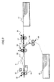
- FIG. 7 is a schematic diagram of a conventional sheet conveying mechanism.
- the reference numeral 32 denotes a pair of horizontal registration rollers
- 33 denotes a stopper
- 34 denotes a pair of feed rollers
- 35 denotes a sheet edge detecting sensor
- 36 denotes a pair of conveying rollers
- 37 and 38 denote sheet conveyance paths
- 39 denotes a sheet
- 40 and 41 denote sheet trays
- C denotes a buffer
- D denotes a sheet conveyance path junction.
- the stopper 33 is arranged at a stage immediately before the pair of horizontal registration rollers 32.
- the stopper can be switched between a position for closing the sheet conveyance path and a position for opening the sheet conveyance path.
- the sheet conveyance path is configured in such a manner that the distance between the pair of horizontal registration rollers 32 and the pair of feed rollers 34 is wide enough for a small-sized sheet to be conveyed.
- there are two sheet conveyance paths at the stage before the pair of feed rollers 34 i.e., the conveyance path 38 extending from the sheet tray 40 provided in the main unit of an image forming apparatus (e.g., a printer) and the conveyance path 37 extending from the sheet tray 41 outside the image forming apparatus.
- Each of these conveyance paths 37 and 38 is provided with one of the pairs of conveying rollers 36 for sending the sheet 39 toward the pair of feed rollers 34. Furthermore, these two conveyance paths 37 and 38 merge at the junction D located on the upstream side of the pair of feed rollers 34.
- the sheet 39 being conveyed by the pair of feed rollers 34 is stopped as the leading edge of the sheet 39 abuts the stopper 33, which stopper 33 is previously situated at a position for closing the sheet conveyance path. At this point, the leading edge of the sheet 39 abuts along the stopper 33, and therefore, a skewed condition of the sheet 39 is corrected. Then, the pair of feed rollers 34 conveys the sheet 39 for a certain amount of time, so that the buffer C is formed between the stopper 33 and the pair of feed rollers 34. Subsequently, the stopper 33 is lowered, thus releasing the leading edge of the sheet 39 from the stopped status.
- the leading edge of the sheet 39 is forced to stick out and wedge into the nip portion of the pair of horizontal registration rollers 32.
- the sheet 39 is released from the nip of the pair of feed rollers 34, a position of the edge (side edge) of the sheet 39 in the sheet main scanning direction is detected by the sheet edge detecting sensor 35, and the correction amount in the sheet main scanning direction is calculated.
- the pair of horizontal registration rollers 32 is caused to horizontally move in the roller axial direction in accordance with the calculated correction amount. Accordingly, by performing the operation of correcting the sheet position in the main scanning direction (horizontal registration) with the pair of horizontal registration rollers 32, it is possible to align the position of the sheet 39 with the main scanning direction without affecting the pair of feed rollers 34.
- the following situation may occur. That is, the trailing edge of the sheet 39 may still be sandwiched (held with pressure) by the pair of conveying rollers 36 when the leading edge of the sheet 39 has wedged into the nip portion of the pair of horizontal registration rollers 32. In such a condition, if the pair of horizontal registration rollers 32 is horizontally moved to correct the sheet position in the main scanning direction, the nip portion of the pair of conveying rollers 36 will act as a resistance.
- the sheet 39 may become twisted and wrinkled, or the skew of the sheet 39 that has been corrected at the stopper 33 may reappear. For these reasons, in this case, the nip portion of the pair of conveying rollers 36 is opened.
- both the stopper and the conveying unit need to be provided with a driving unit, which leads to an increase in the size of the apparatus as well as higher manufacturing costs.
- the present invention provides a sheet aligning device and an image forming apparatus in which one or more of the above-described disadvantages are eliminated.
- a preferred embodiment of the present invention provides a sheet aligning device and an image forming apparatus in which a sheet conveyed in a skewed condition is precisely corrected before being sent to a transfer position under various conditions.
- a preferred embodiment of the present invention provides a sheet conveying mechanism including plural sheet conveyance paths extending in different manners and a junction of the sheet conveyance paths.
- the sheet conveyance paths are provided on an upstream side of a sheet aligning mechanism unit.
- An embodiment of the present invention provides a sheet aligning device including a sheet conveyance path; a detecting unit configured to detect a side edge of a sheet being conveyed in the sheet conveyance path; a stopper provided on an upstream side of the detecting unit and configured to open/close in such a manner as to allow/prevent passage of the sheet through the sheet conveyance path and to position a leading edge of the sheet being conveyed in the sheet conveyance path; a first conveying unit provided on an upstream side of the stopper, the first conveying unit including a pair of first rollers configured to come in contact with/separate from each other; a second conveying unit provided on an upstream side of the first conveying unit, the second conveying unit including a pair of second rollers configured to come in contact with/separate from each other; and a horizontal movement unit configured to move the pair of first rollers in an axial direction of the first rollers based on a detection result output by the detecting unit.
- An embodiment of the present invention provides an image forming apparatus including a sheet conveyance path; at least one pair of conveying rollers; a pair of feed rollers; a pair of horizontal registration rollers; a stopper configured to correct a skewed condition of a sheet being conveyed in the sheet conveyance path and to open/close in such a manner as to allow/prevent passage of the sheet through the sheet conveyance path; and a detecting unit configured to detect a position of a side edge of the sheet, wherein the pair of conveying rollers, the pair of feed rollers, the pair of horizontal registration rollers, the stopper, and the detecting unit are provided along the sheet conveyance path in the stated order starting from an upstream side of a sheet conveyance direction; and the rollers of each of the pair of conveying rollers, the pair of feed rollers, and the pair of horizontal registration rollers are configured to come in contact with/separate from each other, the image forming apparatus further including a control unit configured to perform horizontal registration correction while the pair of horizontal registration rollers
- a sheet aligning device and an image forming apparatus which include a mechanism for precisely positioning the leading edge of the sheet before the sheet is sent to a transfer position. Paper jams are prevented and the leading edge of the sheet is prevented from bending in a registration unit of the mechanism.
- the mechanism can be manufactured at low cost.
- a pair of sheet conveying rollers is positioned on the upstream side of a junction of sheet conveyance paths, and the sheet conveying rollers can be separated from each other.
- the sheet conveyance paths extend in a straight manner or in a curved manner with a curvature radius of 50 mm or more. Accordingly, regardless of the length or thickness of the sheet, it is possible to reduce the resistance applied to the sheet while aligning the sheet conveyance position with the main scanning direction in the sheet aligning mechanism. Consequently, the sheet aligning mechanism can align the sheet conveyance position with high precision.
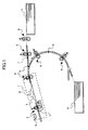
- FIG. 1 illustrates an example of a sheet conveying mechanism according to an embodiment of the present invention.
- the reference numeral 1 denotes a sheet aligning mechanism
- 2 denotes at least one pair of horizontal registration rollers acting as the first pair of rollers
- 3 denotes a stopper with a claw portion on one end
- 4 denotes at least one pair of feed rollers acting as the second pair of rollers
- 5 denotes a detecting sensor
- 6 denotes pairs of conveying rollers acting as the third pairs of rollers
- 7 denotes a straight sheet conveyance path
- 8 denotes a curved sheet conveyance path
- 9 denotes a sheet
- 10 and 11 denote sheet trays
- A denotes a sheet conveyance path junction
- B denotes a buffer.
- the curved sheet conveyance path 8 extending from the sheet tray 10 provided in the main unit of an image forming apparatus and the straight sheet conveyance path 7 extending from the sheet tray 11 outside the image forming apparatus.
- Each of these conveyance paths 7 and 8 is provided with the pairs of conveying rollers 6 for sending the sheet 9 toward the pair of feed rollers 4.
- the distance between adjacent pairs of conveying rollers 6 is 150 mm through 180 mm, so that a small-sized sheet can be conveyed.
- one roller acts as a driving roller and the other roller acts as a following roller, and the driving roller and the following roller can be separated from each other.
- the straight sheet conveyance path 7 and the curved sheet conveyance path 8 merge at the junction A located upstream of the pair of feed rollers 4.
- the sheet aligning mechanism 1 includes the pair of horizontal registration rollers 2, the stopper 3, the pair of feed rollers 4, and the detecting sensor 5 including a CIS sensor, a CCD linear image sensor, etc., for detecting the side edge of the sheet 9.
- the conveyance path between the pair of horizontal registration rollers 2 and the pair of feed rollers 4 has a distance of 100 mm through 180 mm and has a substantially straight shape so that a small-sized sheet can be conveyed therethrough.
- the stopper 3 is arranged immediately downstream of the pair of horizontal registration rollers 2. The stopper 3 can be switched between a position for closing the sheet conveyance path and a position for opening the sheet conveyance path.
- the stopper 3 is lowered to release the leading edge of the sheet 9 and the rollers of the pair of feed rollers 4 are separated from each other.
- the sheet 9 is conveyed by the pair of horizontal registration rollers 2.
- the detecting sensor 5 detects the edge position of the sheet 9 in the main scanning direction.
- a not shown control unit calculates the correction amount of the sheet 9 in the main scanning direction.
- the control unit causes the pair of horizontal registration rollers 2 to horizontally move in the roller axial direction in accordance with the calculated correction amount. Accordingly, the position of the sheet 9 is aligned with the main scanning direction and the operation of correcting the sheet position is completed. Even during the horizontal movement, the horizontal registration rollers 2 rotate in order to keep conveying the sheet 9. Thus, it is possible to minimize wasted time.
- a sheet conveying device e.g., a transfer unit
- rollers arranged on the downstream side of the pair of horizontal registration rollers 2 the rollers of the pair of horizontal registration rollers 2 are separated from each other once again, to be returned to a home position (described below).
- control unit controls at least the pair(s) conveying rollers 6 over which the sheet extends in such a manner that the conveying rollers 6 are separated from each other.
- the sheet 9 is only held by the pair of horizontal registration rollers 2 regardless of the length of the sheet. Therefore, the only resistance applied to the sheet 9 on the upstream side of the pair of horizontal registration rollers 2 is the friction between the sheet 9 and the sheet conveyance path.
- the sheet conveyance path of the sheet aligning mechanism 1 is straight, and therefore, it is possible to minimize the conveyance resistance applied to the sheet 9 while the sheet conveying position is being aligned by the pair of horizontal registration rollers 2.
- FIGS. 2A through 2C are top views of a sheet aligning device according to an embodiment of the present invention.
- FIG. 2A is a partial schematic diagram of an example employing a linear sensor
- FIG. 2B is a partial view of an example employing one photo-coupler
- FIG. 2C is a partial view of an example employing two photo-couplers.
- the reference numeral 12 denotes a unit frame
- 13 denotes a spring
- 14 denotes a cam
- 15 denotes an arrow indicating the direction in which the sheet 9 is moved
- 16 denotes a sheet conveyance reference position
- 17 denotes the shift amount of the position of the sheet side edge.
- the detecting sensor 5 for detecting the sheet side edge position is arranged downstream of the stopper 3.
- the pair of horizontal registration rollers 2 is joined to the unit frame 12, and is configured to be moved in its axial direction by a horizontal movement unit.
- the horizontal movement unit includes the unit frame 12, the spring 13, the cam 14 having a rotational axis provided in the main unit of the image forming apparatus, and a not shown driving source that rotationally drives the cam 14.
- the unit frame 12 is constantly pressed against the cam 14 by the spring 13. By the rotation of the cam 14, the unit frame 12 can be moved in a direction (the direction indicated by the arrow 15) perpendicular to the sheet conveyance direction, that is, the axial direction of the pair of horizontal registration rollers 2.
- the cam 14 rotates to correct the position of the sheet 9 by an amount corresponding to the shift amount 17 so that the sheet side edge is aligned with the predetermined sheet conveyance reference position 16.
- the shift amount of the sheet side edge from the reference position can be easily measured with the conventional technology.
- This shift amount is converted into the rotation amount of the cam 14 so that the cam 14 rotates by an amount corresponding to the correction amount.
- the measured value is output as a discrete value with respect to the length; however, no problems should arise as long as the length corresponding to one bit of the pixel of the CCD array (distance in the shift direction of the side edge) is less than or equal to the allowable error of sheet alignment.
- the horizontal shift amount of the sheet 9 cannot be directly calculated. However, the direction in which the sheet 9 is shifted can be detected. Therefore, the horizontal position of the sheet 9 can be controlled by directly feeding back the output of the photo-coupler to the control unit that controls the cam 14.
- the sheet 9 is once again horizontally moved in a direction toward a position where an output can be obtained.
- the horizontal movement is stopped.
- a stopping error may only be caused by the stopping error of the motor rotating the cam 14 and the error in the time taken by a stop command to reach the cam 14.
- One option is to stop the movement as soon as the output is obtained in both the first and second cases and another option is to stop the movement as soon as the output is turned off in both the first and second cases. Either option can be chosen according to the design of the sheet aligning device.
- the cam 14 is controlled by the control unit to stay at a home position where minimal horizontal movement is caused under regular conditions, i.e., when the sheet 9 is conveyed along the sheet conveyance reference position 16.
- the control unit causes the cam 14 to return to its original position, i.e., the home position.
- the detection positions of the two photo-couplers are arranged to be opposite to each other across the sheet conveyance reference position 16. The distance between the two detection positions approximately corresponds to the allowable error of horizontal registration.
- the photo-coupler A is arranged on the side closer to the sheet center with respect to the sheet conveyance reference position 16. If an output cannot be obtained from the photo-coupler A as light flux is blocked by the sheet 9 but an output can be obtained from the photo-coupler B, the side edge of the sheet 9 is at a desirable position.
- the side edge of the sheet 9 is horizontally shifted. Accordingly, the shift can be corrected by moving the sheet 9 in corresponding directions, until the output of the photo-coupler A is turned off in the former case, and until the output of the photo-coupler B is obtained in the latter case.
- FIG. 3 is a side view of the sheet aligning device according to an embodiment of the present invention.
- the reference numerals 18, 19, and 20 denote springs
- 21 denotes a camshaft
- 22, 23, and 24 denote cams
- 25 denotes a spindle of the stopper 3
- 26 denotes a retract arm for moving together/apart the horizontal registration rollers 2
- 27 denotes a spindle of the retract arm
- 28 denotes a retract arm for moving together/apart the feed rollers 4
- 29 denotes a spindle of the retract arm 28
- 30 denotes a sheet conveyance path.
- the stopper 3 is rotatable about the spindle 25, and is caused to protrude into the sheet conveyance path 30 by the spring 19.
- the stopper 3 is configured to open the sheet conveyance path 30 by being moved by the cam 23.
- the primary parts of the sheet aligning device are first and second conveying units.
- the first conveying unit includes the pair of horizontal registration rollers 2, a driving mechanism, and a contact/separation mechanism thereof.
- the second conveying unit includes the pair of feed rollers 4, a driving mechanism, and a contact/separation mechanism thereof.
- the pair of horizontal registration rollers 2 is arranged upstream of the stopper 3, and the rollers of the pair of horizontal registration rollers 2 are pressed against each other by the spring 18.
- the rollers of the pair of horizontal registration rollers 2 can be separated from each other as the retract arm 26 (hereinafter, simply referred to as "arm 26") rotatable about the spindle 27 is pushed up by the cam 22.
- the rollers of the pair of feed rollers 4 are also pushed against each other by the spring 20.
- the rollers of the pair of feed rollers 4 can be separated from each other as the retract arm 28 (hereinafter, simply referred to as "arm 28") rotatable about the spindle 29 is pushed up by the cam 24.
- the cam 22, the cam 23, and the cam 24 are fixed along the same shaft, i.e., the camshaft 21.
- the cam 22, the cam 23, and the cam 24 perform the following operations in combination, i.e., contact/separation of the pair of horizontal registration rollers 2, opening/closing of the sheet conveying path 30 by the stopper 3, and contact/separation of the pair of feed rollers 4.
- FIGS. 4A through 4E are schematic diagrams illustrating operations according to an embodiment of the present invention.
- FIG. 4A illustrates a status where the horizontal registration rollers 2 are open (separated).
- FIG. 4B illustrates a status where none of the cams are operating.
- FIG. 4C illustrates a status where the stopper 3 and the feed rollers 4 are open.
- FIG. 4D illustrates a status where the stopper 3, the feed rollers 4, and the horizontal registration rollers 2 are open.
- FIG. 4E illustrates a status where the horizontal registration rollers 2 are open.
- FIG. 5 is a timing chart of the operation of the mechanism illustrated in FIGS. 4A through 4E.
- the thick dashed line indicates the status of a cam and its corresponding member.
- IN CONTACT indicates that the corresponding elements are in contact (or operating) and "SEPARATED” indicates the corresponding elements are separated (or opened).
- OPEN indicates that the sheet conveying path 30 is open and "CLOSED” indicates that the sheet conveying path 30 is closed.
- the regions corresponding to FIGS. 4A through 4E have equal sizes in the horizontal direction as a matter of convenience. However, these sizes do not represent the actual region of the rotational angle of the camshaft 21 corresponding to the respective statuses.
- FIGS. 4A through 4E The operation of the mechanism illustrated in FIGS. 4A through 4E is described with reference to FIG. 5.
- the stopper 3 is protruding into the sheet conveyance path 30.
- the horizontal registration rollers 2 are separated from each other as the cam 22 is in contact with the arm 26 to press up one of the rollers against the force of the spring 18.
- the feed rollers 4 are pressed against each other and are sandwiching the sheet 9. Due to the rotation of the pair of feed rollers 4, the sheet 9 is conveyed at a prescribed speed. When the leading edge of the sheet 9 reaches a position immediately before the stopper 3, the conveyance speed is reduced, and then the leading edge of the sheet 9 abuts the stopper 3. Further, the sheet 9 is pushed in the sheet conveyance direction by the pair of feed rollers 4. When a loop 9a is formed in the sheet 9, the pair of feed rollers 4 stops rotating. At this point, due to the force of the loop 9a, the leading edge of the sheet 9a collides with the stopper 3, so that the skewed condition of the sheet 9 is corrected.
- the cam 14 causes the pair of horizontal registration rollers 2 to move in the direction indicated by the arrow 15 while sandwiching and conveying the sheet 9 so that the sheet edge comes to the sheet conveyance reference position 16.
- FIG. 4D when the sheet 9 has reached a not shown sheet conveying unit positioned on the downstream side or an image transfer position, the camshaft 21 rotates so that the cam 22 causes the horizontal registration rollers 2 to be separated. Subsequently, the cam 14 shown in FIG. 2A rotates further or rotates in a reverse direction so that the horizontal registration rollers 2 move in a direction opposite to the direction in which they moved in the status shown in FIG. 4C and return to the home position. At this point, the horizontal registration rollers 2 are still separated, and therefore, even if the middle of the sheet 9 is situated directly beneath the horizontal registration rollers 2, the behavior of the sheet 9 is unaffected.
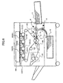
- FIG. 6 illustrates an example of an image forming apparatus to which an embodiment of the present invention is applied.
- the reference numeral 101 denotes photoconductors acting as image carriers
- 102 denotes an optical writing device
- 103 denotes developing devices
- 104 denotes a transfer belt
- 106 denotes a conveying device
- 107 denotes a fixing device
- Y, C, M, and K respectively denote yellow, cyan, magenta, and black, which are development colors.
- the optical writing device 102 forms latent images on the photoconductors 101, the developing devices 103 turn the latent images into visible images, and the images are then transferred onto the transfer belt 104.
- a sheet P supplied from the sheet tray 10 is conveyed by the pair of conveying rollers 6 provided on the curved sheet conveyance path 8 to the pair of feed rollers 4.
- the pair of feed rollers 4 conveys the sheet P so that the leading edge of the sheet P abuts the claw portion of the stopper 3 inserted into the sheet conveyance path.
- the pair of conveying rollers 6 provided on the straight sheet conveyance path 7 conveys the sheet P to the pair of feed rollers 4, and similar operations follow.
- the horizontal registration rollers 2 are open. After a skewed condition of the sheet P is corrected as the leading edge of the sheet P abuts the stopper 3, the horizontal registration rollers 2 sandwich the sheet P. Then, the stopper 3 retreats from the sheet conveyance path and the feed rollers 4 separate from each other. While conveying the sheet P, the horizontal registration rollers 2 move horizontally in accordance with output from a not shown detecting sensor to perform horizontal registration correction. The speed of horizontal movement is determined so that the correction is completed by the time the leading edge of the sheet P reaches a secondary transfer device 105. When the leading edge of the sheet P is nipped by the secondary transfer device 105, the horizontal registration rollers 2 open.
- the sheet P After the image is transferred onto the sheet P from the transfer belt 104, the sheet P is conveyed by the conveying device 106 to the fixing device 107. After the image is fixed onto the sheet P, the sheet P is ejected outside the main unit of the image forming apparatus.
- the curved sheet conveyance path 8 By making the curved sheet conveyance path 8 have a large curvature radius of 50 mm or more, it is possible to reduce the resistance applied to the sheet 9 in the curved sheet conveyance path 8. As a result, in a case where the sheet 9 is longer than the distance between the stopper 3 and the sheet conveyance path junction A, is thick, has body, and thus generates a large conveyance resistance; this sheet 9 is conveyed via the curved sheet conveyance path 8 to the sheet aligning mechanism 1; and the pair of horizontal registration rollers 2 aligns the conveyance position of the sheet 9, the following effects are achieved.
- An embodiment of the present invention has been described by taking as an example a sheet aligning device in a sheet feeding device of an image forming apparatus; however, it is obvious that an embodiment of the present invention is applicable to any general-use printer for preventing a skewed condition or horizontal shifts of a sheet being conveyed.
- a sheet aligning device includes a sheet conveyance path; a detecting unit configured to detect a side edge of a sheet being conveyed in the sheet conveyance path; a stopper provided on an upstream side of the detecting unit and configured to open/close in such a manner as to allow/prevent passage of the sheet through the sheet conveyance path and to position a leading edge of the sheet being conveyed in the sheet conveyance path; a first conveying unit provided on an upstream side of the stopper, the first conveying unit including a pair of first rollers configured to come in contact with/separate from each other; a second conveying unit provided on an upstream side of the first conveying unit, the second conveying unit including a pair of second rollers configured to come in contact with/separate from each other; and a horizontal movement unit configured to move the pair of first rollers in an axial direction of the first rollers based on a detection result output by the detecting unit.
- the second conveying unit conveys the sheet in such a manner that the sheet forms a loop between the stopper and the second conveying unit; after the loop is formed, the first rollers come in contact together, the stopper opens, the second rollers are separated from each other, and while the sheet is being conveyed by the first rollers, the horizontal movement unit moves the first rollers in the axial direction of the first rollers; and after the sheet has passed through the first conveying unit, the horizontal movement unit returns the pair of first rollers to an original position.
- a conveyance speed of the second conveying unit is temporarily reduced when the sheet abuts the stopper.
- operations of opening/closing the stopper, causing the first rollers to come in contact with/separate from each other, and causing the second rollers to come in contact with/separate from each other, are performed in conjunction with each other by a single driving source.
- the operations of opening/closing the stopper, causing the first rollers to come in contact with/separate from each other, and causing the second rollers to come in contact with/separate from each other, are performed by three cams that are fixed to the same camshaft.
- an image forming apparatus includes the sheet aligning device according to one embodiment of the present invention.
- an image forming apparatus includes a sheet conveyance path; at least one pair of conveying rollers; a pair of feed rollers; a pair of horizontal registration rollers; a stopper configured to correct a skewed condition of a sheet being conveyed in the sheet conveyance path and to open/close in such a manner as to allow/prevent passage of the sheet through the sheet conveyance path; and a detecting unit configured to detect a position of a side edge of the sheet, wherein the pair of conveying rollers, the pair of feed rollers, the pair of horizontal registration rollers, the stopper, and the detecting unit are provided along the sheet conveyance path in the stated order starting from an upstream side of a sheet conveyance direction; and the rollers of each of the pair of conveying rollers, the pair of feed rollers, and the pair of horizontal registration rollers are configured to come in contact with/separate from each other, the image forming apparatus further including a control unit configured to perform horizontal registration correction while the pair of horizontal registration roller
- operations of causing the feed rollers to come in contact with/separate from each other, causing the horizontal registration rollers to come in contact with/separate from each other, and opening/closing the stopper are performed by three cams that are fixed to the same camshaft.
- the horizontal registration correction is performed by causing a cam provided in a main unit of the image forming apparatus to move the horizontal registration rollers in an axial direction of the horizontal registration rollers.
- the sheet with the corrected skewed condition being conveyed by the pair of horizontal registration rollers is sandwiched by a sheet conveying device provided on a downstream side of the horizontal registration rollers.
- the sheet conveyance path between the pair of feed rollers and the pair of horizontal registration rollers substantially extends straight; and a distance between axes of the pair of feed rollers and axes of the pair of horizontal registration rollers falls in a range of 100 mm through 180 mm.
- the image forming apparatus further includes another sheet conveyance path that merges with said sheet conveyance path at a junction located between the pair of conveying rollers and the pair of feed rollers, wherein the other sheet conveyance path also comprises at least one pair of conveying rollers provided near the junction, which conveying rollers are configured to come in contact with/separate from each other.
- the sheet conveyance path between the pair of conveying rollers and the pair of feed rollers substantially extends straight or curves with a curvature radius of 50 mm or more.
Landscapes
- Physics & Mathematics (AREA)
- General Physics & Mathematics (AREA)
- Engineering & Computer Science (AREA)
- Mechanical Engineering (AREA)
- Registering Or Overturning Sheets (AREA)
Abstract
Description
- The present invention relates generally to sheet conveying mechanisms in electrophotographic image forming apparatuses, and more particularly to improving precision in correcting the sheet position in the main scanning direction and correcting a skewed condition of a sheet.
- In image forming apparatuses such as laser printers, sheets such as transfer sheets stacked on a sheet feeder are conveyed one by one. Then, a toner image formed on a photoconductive drum or a photoconductive belt is transferred onto each sheet at a transfer position. Finally, the toner image is fixed onto the sheet, thereby obtaining a recorded sheet.
- In such an image forming apparatus, a registration mechanism including a stopper and a pair of rollers is provided just before the transfer position. The registration mechanism corrects the position of a sheet so that the toner image is transferred onto the correct position.
- In this image forming apparatus, the stopper is provided on the sheet conveyance path, which stopper determines the position of a sheet in a direction perpendicular to the sheet conveying direction. The leading edge of a sheet abuts the stopper, and while the leading edge is being stopped, a conveying unit positioned on the upstream side conveys the sheet, so that the sheet forms a loop. Then, the stopper is released, so that the leading edge of the sheet is nipped and conveyed by the pair of rollers situated downstream of the stopper. A detecting unit is arranged near a downstream position of the stopper for detecting side portions of the sheet. A moving unit includes a pair of rollers that is movable in a direction orthogonal to the sheet conveying direction. The detecting unit and the moving unit function to correct the sheet position so that the sheet is positioned along a sheet scanning reference position (see, for example, Patent Document 1).
- FIG. 7 is a schematic diagram of a conventional sheet conveying mechanism.
- In FIG. 7, the
reference numeral 32 denotes a pair of horizontal registration rollers, 33 denotes a stopper, 34 denotes a pair of feed rollers, 35 denotes a sheet edge detecting sensor, 36 denotes a pair of conveying rollers, 37 and 38 denote sheet conveyance paths, 39 denotes a sheet, 40 and 41 denote sheet trays, C denotes a buffer, and D denotes a sheet conveyance path junction. - The
stopper 33 is arranged at a stage immediately before the pair ofhorizontal registration rollers 32. The stopper can be switched between a position for closing the sheet conveyance path and a position for opening the sheet conveyance path. The sheet conveyance path is configured in such a manner that the distance between the pair ofhorizontal registration rollers 32 and the pair offeed rollers 34 is wide enough for a small-sized sheet to be conveyed. Furthermore, there are two sheet conveyance paths at the stage before the pair offeed rollers 34; i.e., theconveyance path 38 extending from thesheet tray 40 provided in the main unit of an image forming apparatus (e.g., a printer) and theconveyance path 37 extending from thesheet tray 41 outside the image forming apparatus. Each of theseconveyance paths conveying rollers 36 for sending thesheet 39 toward the pair offeed rollers 34. Furthermore, these twoconveyance paths feed rollers 34. - Operations of correcting the sheet conveying position and correcting a skewed condition of the
sheet 39 are described. Thesheet 39 being conveyed by the pair offeed rollers 34 is stopped as the leading edge of thesheet 39 abuts thestopper 33, whichstopper 33 is previously situated at a position for closing the sheet conveyance path. At this point, the leading edge of thesheet 39 abuts along thestopper 33, and therefore, a skewed condition of thesheet 39 is corrected. Then, the pair offeed rollers 34 conveys thesheet 39 for a certain amount of time, so that the buffer C is formed between thestopper 33 and the pair offeed rollers 34. Subsequently, thestopper 33 is lowered, thus releasing the leading edge of thesheet 39 from the stopped status. Consequently, due to the rigidity of the buffer C formed in thesheet 39, the leading edge of thesheet 39 is forced to stick out and wedge into the nip portion of the pair ofhorizontal registration rollers 32. At this point, thesheet 39 is released from the nip of the pair offeed rollers 34, a position of the edge (side edge) of thesheet 39 in the sheet main scanning direction is detected by the sheetedge detecting sensor 35, and the correction amount in the sheet main scanning direction is calculated. Then, the pair ofhorizontal registration rollers 32 is caused to horizontally move in the roller axial direction in accordance with the calculated correction amount. Accordingly, by performing the operation of correcting the sheet position in the main scanning direction (horizontal registration) with the pair ofhorizontal registration rollers 32, it is possible to align the position of thesheet 39 with the main scanning direction without affecting the pair offeed rollers 34. - In this sheet conveying mechanism, to correct the sheet conveying position and to correct a skewed condition of a sheet that is longer than the distance between the pair of
horizontal registration rollers 32 and the pair ofconveying rollers 36, the following situation may occur. That is, the trailing edge of thesheet 39 may still be sandwiched (held with pressure) by the pair ofconveying rollers 36 when the leading edge of thesheet 39 has wedged into the nip portion of the pair ofhorizontal registration rollers 32. In such a condition, if the pair ofhorizontal registration rollers 32 is horizontally moved to correct the sheet position in the main scanning direction, the nip portion of the pair ofconveying rollers 36 will act as a resistance. As a result, thesheet 39 may become twisted and wrinkled, or the skew of thesheet 39 that has been corrected at thestopper 33 may reappear. For these reasons, in this case, the nip portion of the pair ofconveying rollers 36 is opened. - Incidentally, when the leading edge of the
sheet 39 is released from the stopped status by lowering thestopper 33 after the buffer C has been formed between thestopper 33 and the pair offeed rollers 34, the following situation may occur if thesheet 39 is curled or if thesheet 39 has low rigidity. That is, thesheet 39 may become buckled or skewed before being nipped by the pair ofhorizontal registration rollers 32, so that the position of thesheet 39 is shifted or a paper jam occurs. Meanwhile, if thesheet 39 is highly rigid, the skew of thesheet 39 corrected at thestopper 33 may reappear before thesheet 39 wedges into the nip portion of the pair ofhorizontal registration rollers 32. If this happens, it would be meaningless to correct the skew at thestopper 33. To solve these problems, there is a configuration in which thestopper 33 is arranged on the downstream side of the pair of horizontal registration rollers 32 (see, for example, Patent Document 2). - In the above configuration, both the stopper and the conveying unit need to be provided with a driving unit, which leads to an increase in the size of the apparatus as well as higher manufacturing costs.
- Even if the above problems are solved, when conveying a thick sheet that has body and that is longer than the distance between the pair of
horizontal registration rollers 32 and the sheet conveyance path junction D, a problem arises if the curvature radius of each of the sheet conveyance paths between the corresponding sheet tray and the pair offeed rollers 34 is too small. Specifically, the trailing edge of the sheet remaining in the sheet conveyance path receives a large conveyance resistance that is caused by the small curvature radius of the sheet conveyance path. As a result, the resistance caused by the small curvature radius of the sheet conveyance path obstructs the movement of conveying thesheet 39 in the main scanning direction when correcting the position of thesheet 39 in the main scanning direction with the pair ofhorizontal registration rollers 32. This decreases the precision of conveying and aligning the sheet. - Patent Document 1:
Japanese Patent No. 2893540 - Patent Document 2:
Japanese Laid-Open Patent Application No. H10-203690 - The present invention provides a sheet aligning device and an image forming apparatus in which one or more of the above-described disadvantages are eliminated.
- A preferred embodiment of the present invention provides a sheet aligning device and an image forming apparatus in which a sheet conveyed in a skewed condition is precisely corrected before being sent to a transfer position under various conditions.
- Furthermore, a preferred embodiment of the present invention provides a sheet conveying mechanism including plural sheet conveyance paths extending in different manners and a junction of the sheet conveyance paths. The sheet conveyance paths are provided on an upstream side of a sheet aligning mechanism unit. When the trailing edge of a sheet is remaining on the upstream side of the junction in the sheet conveyance path while correcting the horizontal sheet conveyance position and correcting the skewed condition of the sheet, the resistance applied to the trailing edge of the sheet is reduced. Therefore, the horizontal sheet conveyance position and the skewed condition of the sheet can be precisely corrected.
- An embodiment of the present invention provides a sheet aligning device including a sheet conveyance path; a detecting unit configured to detect a side edge of a sheet being conveyed in the sheet conveyance path; a stopper provided on an upstream side of the detecting unit and configured to open/close in such a manner as to allow/prevent passage of the sheet through the sheet conveyance path and to position a leading edge of the sheet being conveyed in the sheet conveyance path; a first conveying unit provided on an upstream side of the stopper, the first conveying unit including a pair of first rollers configured to come in contact with/separate from each other; a second conveying unit provided on an upstream side of the first conveying unit, the second conveying unit including a pair of second rollers configured to come in contact with/separate from each other; and a horizontal movement unit configured to move the pair of first rollers in an axial direction of the first rollers based on a detection result output by the detecting unit.
- An embodiment of the present invention provides an image forming apparatus including a sheet conveyance path; at least one pair of conveying rollers; a pair of feed rollers; a pair of horizontal registration rollers; a stopper configured to correct a skewed condition of a sheet being conveyed in the sheet conveyance path and to open/close in such a manner as to allow/prevent passage of the sheet through the sheet conveyance path; and a detecting unit configured to detect a position of a side edge of the sheet, wherein the pair of conveying rollers, the pair of feed rollers, the pair of horizontal registration rollers, the stopper, and the detecting unit are provided along the sheet conveyance path in the stated order starting from an upstream side of a sheet conveyance direction; and the rollers of each of the pair of conveying rollers, the pair of feed rollers, and the pair of horizontal registration rollers are configured to come in contact with/separate from each other, the image forming apparatus further including a control unit configured to perform horizontal registration correction while the pair of horizontal registration rollers is conveying the sheet after the skewed condition has been corrected by the stopper, the horizontal registration correction being performed based on a detection result output by the detecting unit, the control unit also being configured to control the pair of conveying rollers and the pair of feed rollers, which are provided on an upstream side of the pair of horizontal registration rollers, not to sandwich the sheet at least during the horizontal registration correction.
- According to one embodiment of the present invention, a sheet aligning device and an image forming apparatus are provided, which include a mechanism for precisely positioning the leading edge of the sheet before the sheet is sent to a transfer position. Paper jams are prevented and the leading edge of the sheet is prevented from bending in a registration unit of the mechanism. The mechanism can be manufactured at low cost.
- According to one embodiment of the present invention, a pair of sheet conveying rollers is positioned on the upstream side of a junction of sheet conveyance paths, and the sheet conveying rollers can be separated from each other. On the upstream side of the junction of sheet conveyance paths, the sheet conveyance paths extend in a straight manner or in a curved manner with a curvature radius of 50 mm or more. Accordingly, regardless of the length or thickness of the sheet, it is possible to reduce the resistance applied to the sheet while aligning the sheet conveyance position with the main scanning direction in the sheet aligning mechanism. Consequently, the sheet aligning mechanism can align the sheet conveyance position with high precision.
- Other objects, features and advantages of the present invention will become more apparent from the following detailed description when read in conjunction with the accompanying drawings, in which:
- FIG. 1 illustrates an example of a sheet conveying mechanism according to an embodiment of the present invention;
- FIGS. 2A through 2C are top views of a sheet aligning device according to an embodiment of the present invention;
- FIG. 3 is a side view of the sheet aligning device according to an embodiment of the present invention;
- FIGS. 4A through 4E are schematic diagrams illustrating operations according to an embodiment of the present invention;
- FIG. 5 is a timing chart of the operations of the mechanism illustrated in FIGS. 4A through 4E;
- FIG. 6 illustrates an example of an image forming apparatus to which an embodiment of the present invention is applied; and
- FIG. 7 is a schematic diagram of a conventional sheet conveying mechanism.
- A description is given, with reference to the accompanying drawings, of an embodiment of the present invention.
- FIG. 1 illustrates an example of a sheet conveying mechanism according to an embodiment of the present invention.
- In FIG. 1, the
reference numeral 1 denotes a sheet aligning mechanism, 2 denotes at least one pair of horizontal registration rollers acting as the first pair of rollers, 3 denotes a stopper with a claw portion on one end, 4 denotes at least one pair of feed rollers acting as the second pair of rollers, 5 denotes a detecting sensor, 6 denotes pairs of conveying rollers acting as the third pairs of rollers, 7 denotes a straight sheet conveyance path, 8 denotes a curved sheet conveyance path, 9 denotes a sheet, 10 and 11 denote sheet trays, A denotes a sheet conveyance path junction, and B denotes a buffer. - There are two sheet conveyance paths at the stage before the pair of
feed rollers 4; i.e., the curved sheet conveyance path 8 extending from thesheet tray 10 provided in the main unit of an image forming apparatus and the straightsheet conveyance path 7 extending from thesheet tray 11 outside the image forming apparatus. Each of theseconveyance paths 7 and 8 is provided with the pairs of conveyingrollers 6 for sending thesheet 9 toward the pair offeed rollers 4. The distance between adjacent pairs of conveyingrollers 6 is 150 mm through 180 mm, so that a small-sized sheet can be conveyed. In each of the pairs of rollers, one roller acts as a driving roller and the other roller acts as a following roller, and the driving roller and the following roller can be separated from each other. Furthermore, the straightsheet conveyance path 7 and the curved sheet conveyance path 8 merge at the junction A located upstream of the pair offeed rollers 4. - The
sheet aligning mechanism 1 includes the pair ofhorizontal registration rollers 2, thestopper 3, the pair offeed rollers 4, and the detectingsensor 5 including a CIS sensor, a CCD linear image sensor, etc., for detecting the side edge of thesheet 9. The conveyance path between the pair ofhorizontal registration rollers 2 and the pair offeed rollers 4 has a distance of 100 mm through 180 mm and has a substantially straight shape so that a small-sized sheet can be conveyed therethrough. Unlike conventional stoppers, thestopper 3 is arranged immediately downstream of the pair ofhorizontal registration rollers 2. Thestopper 3 can be switched between a position for closing the sheet conveyance path and a position for opening the sheet conveyance path. - Operations of correcting the sheet conveying position and correcting a skewed condition of the
sheet 9 in thesheet aligning mechanism 1 are described. Before the leading edge of thesheet 9 reaches the pair ofhorizontal registration rollers 2, the rollers of the pair ofhorizontal registration rollers 2 are separated from each other, and thestopper 3 is raised in such a manner that its claw portion closes the sheet conveyance path. The conveyance speed is reduced immediately before the leading edge of thesheet 9 abuts the claw portion of thestopper 3. Then, thesheet 9 is pushed into thestopper 3 while being sandwiched by the pair offeed rollers 4. After the buffer B is formed in thesheet 9 between thestopper 3 and the pair offeed rollers 4, the leading edge of thesheet 9 is caused to abut along the claw portion of thestopper 3. Accordingly, a skewed condition of thesheet 9 is corrected. Then, thesheet 9 is sandwiched by the pair ofhorizontal registration rollers 2. The following describes an example where a CCD linear image sensor is employed as the detectingsensor 5. - Subsequently, the
stopper 3 is lowered to release the leading edge of thesheet 9 and the rollers of the pair offeed rollers 4 are separated from each other. Thesheet 9 is conveyed by the pair ofhorizontal registration rollers 2. When thesheet 9 reaches the detectingsensor 5, the detectingsensor 5 detects the edge position of thesheet 9 in the main scanning direction. A not shown control unit calculates the correction amount of thesheet 9 in the main scanning direction. Further, the control unit causes the pair ofhorizontal registration rollers 2 to horizontally move in the roller axial direction in accordance with the calculated correction amount. Accordingly, the position of thesheet 9 is aligned with the main scanning direction and the operation of correcting the sheet position is completed. Even during the horizontal movement, thehorizontal registration rollers 2 rotate in order to keep conveying thesheet 9. Thus, it is possible to minimize wasted time. - Subsequently, when the
sheet 9 is sandwiched by a sheet conveying device (e.g., a transfer unit) including not shown rollers arranged on the downstream side of the pair ofhorizontal registration rollers 2, the rollers of the pair ofhorizontal registration rollers 2 are separated from each other once again, to be returned to a home position (described below). - When performing the sheet aligning operation for a conveyed sheet that is longer than the distance between the
stopper 3 and the pair of conveyingrollers 6 closest to the sheet conveyance path junction A, the control unit controls at least the pair(s) conveyingrollers 6 over which the sheet extends in such a manner that the conveyingrollers 6 are separated from each other. - In the sheet aligning operation performed by the sheet conveying mechanism formed as described above, at the stage of horizontally moving the pair of
horizontal registration rollers 2 in the roller axial direction, thesheet 9 is only held by the pair ofhorizontal registration rollers 2 regardless of the length of the sheet. Therefore, the only resistance applied to thesheet 9 on the upstream side of the pair ofhorizontal registration rollers 2 is the friction between thesheet 9 and the sheet conveyance path. As described above, the sheet conveyance path of thesheet aligning mechanism 1 is straight, and therefore, it is possible to minimize the conveyance resistance applied to thesheet 9 while the sheet conveying position is being aligned by the pair ofhorizontal registration rollers 2. As a result, while the pair ofhorizontal registration rollers 2 moves horizontally, the force with which thesheet 9 is held by the pair ofhorizontal registration rollers 2 significantly exceeds the resistance applied to thesheet 9 on the upstream side of the pair ofhorizontal registration rollers 2. Hence, after the skewed condition of thesheet 9 is corrected at thestopper 3, thesheet 9 is prevented from becoming twisted and wrinkled due to a resistance applied to thesheet 9 on the upstream side of the pair ofhorizontal registration rollers 2. Thus, operations of conveying and aligning thesheet 9 can be performed with high precision in thesheet aligning mechanism 1. - FIGS. 2A through 2C are top views of a sheet aligning device according to an embodiment of the present invention. FIG. 2A is a partial schematic diagram of an example employing a linear sensor, FIG. 2B is a partial view of an example employing one photo-coupler, and FIG. 2C is a partial view of an example employing two photo-couplers.
- In FIGS. 2A through 2C, the
reference numeral 12 denotes a unit frame, 13 denotes a spring, 14 denotes a cam, 15 denotes an arrow indicating the direction in which thesheet 9 is moved, 16 denotes a sheet conveyance reference position, and 17 denotes the shift amount of the position of the sheet side edge. - The detecting
sensor 5 for detecting the sheet side edge position is arranged downstream of thestopper 3. The pair ofhorizontal registration rollers 2 is joined to theunit frame 12, and is configured to be moved in its axial direction by a horizontal movement unit. The horizontal movement unit includes theunit frame 12, thespring 13, thecam 14 having a rotational axis provided in the main unit of the image forming apparatus, and a not shown driving source that rotationally drives thecam 14. - The
unit frame 12 is constantly pressed against thecam 14 by thespring 13. By the rotation of thecam 14, theunit frame 12 can be moved in a direction (the direction indicated by the arrow 15) perpendicular to the sheet conveyance direction, that is, the axial direction of the pair ofhorizontal registration rollers 2. - When the detecting
sensor 5 detects that the sheet side edge is shifted from the sheetconveyance reference position 16, thecam 14 rotates to correct the position of thesheet 9 by an amount corresponding to theshift amount 17 so that the sheet side edge is aligned with the predetermined sheetconveyance reference position 16. - By employing a linear image sensor including a CCD array as the detecting
sensor 5 as shown in FIG. 2A, the shift amount of the sheet side edge from the reference position can be easily measured with the conventional technology. This shift amount is converted into the rotation amount of thecam 14 so that thecam 14 rotates by an amount corresponding to the correction amount. The measured value is output as a discrete value with respect to the length; however, no problems should arise as long as the length corresponding to one bit of the pixel of the CCD array (distance in the shift direction of the side edge) is less than or equal to the allowable error of sheet alignment. - As shown in FIG. 2B, when a simple photo-coupler for detecting one point is employed as the detecting
sensor 5, the horizontal shift amount of thesheet 9 cannot be directly calculated. However, the direction in which thesheet 9 is shifted can be detected. Therefore, the horizontal position of thesheet 9 can be controlled by directly feeding back the output of the photo-coupler to the control unit that controls thecam 14. - This control method is described below. In a first case where light flux is blocked by the
sheet 9 such that an output cannot be obtained, thesheet 9 is horizontally moved in a direction toward a position where an output can be obtained (direction toward the sheet center). As soon as an output is obtained, thesheet 9 is stopped. Meanwhile, in a second case where light flux is not blocked by thesheet 9, thesheet 9 is horizontally moved in a direction opposite to that of the first case until an output cannot be obtained. The horizontal movement can be stopped as soon as the output is turned off; however, the stopping position would not be the same as that of the first case. Accordingly, a large error may often be caused between the stopping position of the first case and the stopping position of the second case. Thus, when the output is turned off, thesheet 9 is once again horizontally moved in a direction toward a position where an output can be obtained. As soon as an output is obtained, the horizontal movement is stopped. By this method, a stopping error may only be caused by the stopping error of the motor rotating thecam 14 and the error in the time taken by a stop command to reach thecam 14. One option is to stop the movement as soon as the output is obtained in both the first and second cases and another option is to stop the movement as soon as the output is turned off in both the first and second cases. Either option can be chosen according to the design of the sheet aligning device. - The
cam 14 is controlled by the control unit to stay at a home position where minimal horizontal movement is caused under regular conditions, i.e., when thesheet 9 is conveyed along the sheetconveyance reference position 16. Thus, after rotating thecam 14 so that the pair ofhorizontal registration rollers 2 is horizontally moved, and when the correction has been made, the control unit causes thecam 14 to return to its original position, i.e., the home position. - There is a method of employing two photo-couplers as the detecting
sensor 5. The detection positions of the two photo-couplers (supposedly photo-couplers A and B) are arranged to be opposite to each other across the sheetconveyance reference position 16. The distance between the two detection positions approximately corresponds to the allowable error of horizontal registration. - For example, the photo-coupler A is arranged on the side closer to the sheet center with respect to the sheet
conveyance reference position 16. If an output cannot be obtained from the photo-coupler A as light flux is blocked by thesheet 9 but an output can be obtained from the photo-coupler B, the side edge of thesheet 9 is at a desirable position. When outputs are obtained from both photo-couplers A and B, or when outputs of both photo-couplers A and B are turned off, the side edge of thesheet 9 is horizontally shifted. Accordingly, the shift can be corrected by moving thesheet 9 in corresponding directions, until the output of the photo-coupler A is turned off in the former case, and until the output of the photo-coupler B is obtained in the latter case. - FIG. 3 is a side view of the sheet aligning device according to an embodiment of the present invention.
- In FIG. 3, the
reference numerals stopper horizontal registration rollers arm feed rollers arm - The
stopper 3 is rotatable about thespindle 25, and is caused to protrude into thesheet conveyance path 30 by thespring 19. Thestopper 3 is configured to open thesheet conveyance path 30 by being moved by thecam 23. - The primary parts of the sheet aligning device are first and second conveying units. The first conveying unit includes the pair of
horizontal registration rollers 2, a driving mechanism, and a contact/separation mechanism thereof. The second conveying unit includes the pair offeed rollers 4, a driving mechanism, and a contact/separation mechanism thereof. - The pair of
horizontal registration rollers 2 is arranged upstream of thestopper 3, and the rollers of the pair ofhorizontal registration rollers 2 are pressed against each other by thespring 18. The rollers of the pair ofhorizontal registration rollers 2 can be separated from each other as the retract arm 26 (hereinafter, simply referred to as "arm 26") rotatable about thespindle 27 is pushed up by thecam 22. Similarly, the rollers of the pair offeed rollers 4 are also pushed against each other by thespring 20. The rollers of the pair offeed rollers 4 can be separated from each other as the retract arm 28 (hereinafter, simply referred to as "arm 28") rotatable about thespindle 29 is pushed up by thecam 24. Thecam 22, thecam 23, and thecam 24 are fixed along the same shaft, i.e., thecamshaft 21. As thecamshaft 21 rotates by a predetermined angle, thecam 22, thecam 23, and thecam 24 perform the following operations in combination, i.e., contact/separation of the pair ofhorizontal registration rollers 2, opening/closing of thesheet conveying path 30 by thestopper 3, and contact/separation of the pair offeed rollers 4. - FIGS. 4A through 4E are schematic diagrams illustrating operations according to an embodiment of the present invention. FIG. 4A illustrates a status where the
horizontal registration rollers 2 are open (separated). FIG. 4B illustrates a status where none of the cams are operating. FIG. 4C illustrates a status where thestopper 3 and thefeed rollers 4 are open. FIG. 4D illustrates a status where thestopper 3, thefeed rollers 4, and thehorizontal registration rollers 2 are open. FIG. 4E illustrates a status where thehorizontal registration rollers 2 are open. - In each of the FIGS. 4A through 4E, the elements denoted by a reference numeral are relevant to the illustrated operation.
- FIG. 5 is a timing chart of the operation of the mechanism illustrated in FIGS. 4A through 4E.
- In FIG. 5, the thick dashed line indicates the status of a cam and its corresponding member. "IN CONTACT" indicates that the corresponding elements are in contact (or operating) and "SEPARATED" indicates the corresponding elements are separated (or opened). "OPEN" indicates that the
sheet conveying path 30 is open and "CLOSED" indicates that thesheet conveying path 30 is closed. The regions corresponding to FIGS. 4A through 4E have equal sizes in the horizontal direction as a matter of convenience. However, these sizes do not represent the actual region of the rotational angle of thecamshaft 21 corresponding to the respective statuses. - The operation of the mechanism illustrated in FIGS. 4A through 4E is described with reference to FIG. 5.
- In FIG. 4A, the
stopper 3 is protruding into thesheet conveyance path 30. Thehorizontal registration rollers 2 are separated from each other as thecam 22 is in contact with thearm 26 to press up one of the rollers against the force of thespring 18. Thefeed rollers 4 are pressed against each other and are sandwiching thesheet 9. Due to the rotation of the pair offeed rollers 4, thesheet 9 is conveyed at a prescribed speed. When the leading edge of thesheet 9 reaches a position immediately before thestopper 3, the conveyance speed is reduced, and then the leading edge of thesheet 9 abuts thestopper 3. Further, thesheet 9 is pushed in the sheet conveyance direction by the pair offeed rollers 4. When aloop 9a is formed in thesheet 9, the pair offeed rollers 4 stops rotating. At this point, due to the force of theloop 9a, the leading edge of thesheet 9a collides with thestopper 3, so that the skewed condition of thesheet 9 is corrected. - In FIG. 5, in the region corresponding to FIG. 4A, the
cam 22 and thearm 26 are "IN CONTACT", and therefore, thehorizontal registration rollers 2 are "SEPARATED". Thecam 23 and anarm 3a are "SEPARATED", and therefore, thesheet conveyance path 30 is "CLOSED". Thecam 24 and thearm 28 are "SEPARATED", and therefore, thefeed rollers 4 are as "IN CONTACT". - In FIG. 4B, as the
camshaft 21 rotates, thecam 22 comes off thearm 26, and thehorizontal registration rollers 2 are pressed against each other by the force of thespring 18. At this point, thesheet 9 is sandwiched by the pair ofhorizontal registration rollers 2, after its skewed condition is corrected at thestopper 3. At this point, thecam 23 and thecam 24 are not yet in contact with their respective arms. - In FIG. 5, in the region corresponding to FIG. 4B, all of the cams are in a "SEPARATED" status, and their corresponding rollers or arms are in a stable status due to forces of springs. Specifically, the
horizontal registration rollers 2 are "IN CONTACT", thefeed rollers 4 are "IN CONTACT", and thesheet conveyance path 30 is "CLOSED" by the claw portion of thestopper 3. - In FIG. 4C, as the
camshaft 21 rotates further, thecam 23 contacts thearm 3a on the side opposite to the claw portion, across thespindle 25 of thestopper 3. As a result, thestopper 3 is rotated in a counter-clockwise direction against the force of thespring 19, so that the claw portion of thestopper 3 retreats and thesheet conveyance path 30 is opened. Furthermore, thecam 24 contacts thearm 28 so that thearm 28 is rotated in a counter-clockwise direction against the force of thespring 20 and thefeed rollers 4 are separated. In this situation, the pair ofhorizontal registration rollers 2 conveys thesheet 9. The not shown photosensor (detecting sensor) 5 detects the sheet side edge position. Theshift amount 17 from the sheetconveyance reference position 16 shown in FIG. 2A and the detected sheet side edge position is converted into the rotation amount of thecam 14. Thecam 14 causes the pair ofhorizontal registration rollers 2 to move in the direction indicated by thearrow 15 while sandwiching and conveying thesheet 9 so that the sheet edge comes to the sheetconveyance reference position 16. - In FIG. 5, in the region corresponding to FIG. 4C, the mechanism is operating such that only the
horizontal registration rollers 2 are "IN CONTACT". The pair offeed rollers 4 and thesheet conveyance path 30 are both "OPEN". - In FIG. 4D, when the
sheet 9 has reached a not shown sheet conveying unit positioned on the downstream side or an image transfer position, thecamshaft 21 rotates so that thecam 22 causes thehorizontal registration rollers 2 to be separated. Subsequently, thecam 14 shown in FIG. 2A rotates further or rotates in a reverse direction so that thehorizontal registration rollers 2 move in a direction opposite to the direction in which they moved in the status shown in FIG. 4C and return to the home position. At this point, thehorizontal registration rollers 2 are still separated, and therefore, even if the middle of thesheet 9 is situated directly beneath thehorizontal registration rollers 2, the behavior of thesheet 9 is unaffected. - In FIG. 5, in the region corresponding to FIG. 4D, all of the elements of the mechanism are open. That is, the
horizontal registration rollers 2 and thefeed rollers 4 are "SEPARATED", and thesheet conveyance path 30 is "OPEN". Under these conditions, the trailing edge of thesheet 9 passes through thefeed rollers 4. - In FIG. 4E, before a next sheet 9' reaches the pair of
feed rollers 4, thecamshaft 21 rotates so that thecam 24 causes thefeed rollers 4 to be pressed against each other, in order to be prepared to convey the next sheet 9'. Furthermore, after the trailing edge of thesheet 9 has passed the claw portion of thestopper 3 and before the leading edge of the next sheet 9' reaches thestopper 3, thecam 23 rotates to no longer be in contact with thearm 3a. Thus, the claw portion of thestopper 3 protrudes into thesheet conveyance path 30, returning to the status illustrated in FIG. 4A. Accordingly, the position of the next sheet 9' can be similarly corrected. - In FIG. 5, in the region corresponding to FIG. 4E, in a status where the
sheet conveyance path 30 is "OPEN" and thehorizontal registration rollers 2 are "IN CONTACT", thesheet 9 is conveyed and passed on to a conveying mechanism on a downstream side. Thesheet 9 has already passed through the sheet aligning device, and therefore, thefeed rollers 4 come "IN CONTACT" to be prepared to convey the next sheet. - FIG. 6 illustrates an example of an image forming apparatus to which an embodiment of the present invention is applied.
- In FIG. 6, the
reference numeral 101 denotes photoconductors acting as image carriers, 102 denotes an optical writing device, 103 denotes developing devices, 104 denotes a transfer belt, 106 denotes a conveying device, 107 denotes a fixing device, and Y, C, M, and K respectively denote yellow, cyan, magenta, and black, which are development colors. - The
optical writing device 102 forms latent images on thephotoconductors 101, the developingdevices 103 turn the latent images into visible images, and the images are then transferred onto thetransfer belt 104. - A sheet P supplied from the
sheet tray 10 is conveyed by the pair of conveyingrollers 6 provided on the curved sheet conveyance path 8 to the pair offeed rollers 4. The pair offeed rollers 4 conveys the sheet P so that the leading edge of the sheet P abuts the claw portion of thestopper 3 inserted into the sheet conveyance path. When a sheet P is supplied from thesheet tray 11, the pair of conveyingrollers 6 provided on the straightsheet conveyance path 7 conveys the sheet P to the pair offeed rollers 4, and similar operations follow. - At this point, the
horizontal registration rollers 2 are open. After a skewed condition of the sheet P is corrected as the leading edge of the sheet P abuts thestopper 3, thehorizontal registration rollers 2 sandwich the sheet P. Then, thestopper 3 retreats from the sheet conveyance path and thefeed rollers 4 separate from each other. While conveying the sheet P, thehorizontal registration rollers 2 move horizontally in accordance with output from a not shown detecting sensor to perform horizontal registration correction. The speed of horizontal movement is determined so that the correction is completed by the time the leading edge of the sheet P reaches asecondary transfer device 105. When the leading edge of the sheet P is nipped by thesecondary transfer device 105, thehorizontal registration rollers 2 open. - After the image is transferred onto the sheet P from the
transfer belt 104, the sheet P is conveyed by the conveyingdevice 106 to thefixing device 107. After the image is fixed onto the sheet P, the sheet P is ejected outside the main unit of the image forming apparatus. - Next, a description is given of the curved sheet conveyance path 8. By making the curved sheet conveyance path 8 have a large curvature radius of 50 mm or more, it is possible to reduce the resistance applied to the
sheet 9 in the curved sheet conveyance path 8. As a result, in a case where thesheet 9 is longer than the distance between thestopper 3 and the sheet conveyance path junction A, is thick, has body, and thus generates a large conveyance resistance; thissheet 9 is conveyed via the curved sheet conveyance path 8 to thesheet aligning mechanism 1; and the pair ofhorizontal registration rollers 2 aligns the conveyance position of thesheet 9, the following effects are achieved. That is, such a configuration (i.e., with a large curvature radius) reduces the resistance applied to the rear end of thesheet 9, eliminates fluctuations in the precision in aligning the conveyance position, which fluctuations are caused by differences in length/thickness/rigidity of thesheet 9, and realizes high precision in aligning the conveyance position for a wide variety of sheets. - An embodiment of the present invention has been described by taking as an example a sheet aligning device in a sheet feeding device of an image forming apparatus; however, it is obvious that an embodiment of the present invention is applicable to any general-use printer for preventing a skewed condition or horizontal shifts of a sheet being conveyed.
- According to one embodiment of the present invention, a sheet aligning device includes a sheet conveyance path; a detecting unit configured to detect a side edge of a sheet being conveyed in the sheet conveyance path; a stopper provided on an upstream side of the detecting unit and configured to open/close in such a manner as to allow/prevent passage of the sheet through the sheet conveyance path and to position a leading edge of the sheet being conveyed in the sheet conveyance path; a first conveying unit provided on an upstream side of the stopper, the first conveying unit including a pair of first rollers configured to come in contact with/separate from each other; a second conveying unit provided on an upstream side of the first conveying unit, the second conveying unit including a pair of second rollers configured to come in contact with/separate from each other; and a horizontal movement unit configured to move the pair of first rollers in an axial direction of the first rollers based on a detection result output by the detecting unit.
- Additionally, in the sheet aligning device, while the first rollers are separated, the second conveying unit conveys the sheet in such a manner that the sheet forms a loop between the stopper and the second conveying unit; after the loop is formed, the first rollers come in contact together, the stopper opens, the second rollers are separated from each other, and while the sheet is being conveyed by the first rollers, the horizontal movement unit moves the first rollers in the axial direction of the first rollers; and after the sheet has passed through the first conveying unit, the horizontal movement unit returns the pair of first rollers to an original position.
- Additionally, in the sheet aligning device, a conveyance speed of the second conveying unit is temporarily reduced when the sheet abuts the stopper.
- Additionally, in the sheet aligning device, operations of opening/closing the stopper, causing the first rollers to come in contact with/separate from each other, and causing the second rollers to come in contact with/separate from each other, are performed in conjunction with each other by a single driving source.
- Additionally, in the sheet aligning device, the operations of opening/closing the stopper, causing the first rollers to come in contact with/separate from each other, and causing the second rollers to come in contact with/separate from each other, are performed by three cams that are fixed to the same camshaft.
- Additionally, an image forming apparatus includes the sheet aligning device according to one embodiment of the present invention.
- According to one embodiment of the present invention, an image forming apparatus includes a sheet conveyance path; at least one pair of conveying rollers; a pair of feed rollers; a pair of horizontal registration rollers; a stopper configured to correct a skewed condition of a sheet being conveyed in the sheet conveyance path and to open/close in such a manner as to allow/prevent passage of the sheet through the sheet conveyance path; and a detecting unit configured to detect a position of a side edge of the sheet, wherein the pair of conveying rollers, the pair of feed rollers, the pair of horizontal registration rollers, the stopper, and the detecting unit are provided along the sheet conveyance path in the stated order starting from an upstream side of a sheet conveyance direction; and the rollers of each of the pair of conveying rollers, the pair of feed rollers, and the pair of horizontal registration rollers are configured to come in contact with/separate from each other, the image forming apparatus further including a control unit configured to perform horizontal registration correction while the pair of horizontal registration rollers is conveying the sheet after the skewed condition has been corrected by the stopper, the horizontal registration correction being performed based on a detection result output by the detecting unit, the control unit also being configured to control the pair of conveying rollers and the pair of feed rollers, which are provided on an upstream side of the pair of horizontal registration rollers, not to sandwich the sheet at least during the horizontal registration correction.
- Additionally, in the image forming apparatus, operations of causing the feed rollers to come in contact with/separate from each other, causing the horizontal registration rollers to come in contact with/separate from each other, and opening/closing the stopper, are performed by three cams that are fixed to the same camshaft.
- Additionally, in the image forming apparatus, the horizontal registration correction is performed by causing a cam provided in a main unit of the image forming apparatus to move the horizontal registration rollers in an axial direction of the horizontal registration rollers.
- Additionally, in the image forming apparatus, after the horizontal registration correction is completed, the sheet with the corrected skewed condition being conveyed by the pair of horizontal registration rollers is sandwiched by a sheet conveying device provided on a downstream side of the horizontal registration rollers.
- Additionally, in the image forming apparatus, the sheet conveyance path between the pair of feed rollers and the pair of horizontal registration rollers substantially extends straight; and a distance between axes of the pair of feed rollers and axes of the pair of horizontal registration rollers falls in a range of 100 mm through 180 mm.
- Additionally, the image forming apparatus further includes another sheet conveyance path that merges with said sheet conveyance path at a junction located between the pair of conveying rollers and the pair of feed rollers, wherein the other sheet conveyance path also comprises at least one pair of conveying rollers provided near the junction, which conveying rollers are configured to come in contact with/separate from each other.
- Additionally, in the image forming apparatus, the sheet conveyance path between the pair of conveying rollers and the pair of feed rollers substantially extends straight or curves with a curvature radius of 50 mm or more.
- The present invention is not limited to the specifically disclosed embodiment, and variations and modifications may be made without departing from the scope of the present invention.
Claims (13)
- A sheet aligning device comprising:a sheet conveyance path;a detecting unit configured to detect a side edge of a sheet being conveyed in the sheet conveyance path;a stopper provided on an upstream side of the detecting unit and configured to open/close in such a manner as to allow/prevent passage of the sheet through the sheet conveyance path and to position a leading edge of the sheet being conveyed in the sheet conveyance path;a first conveying unit provided on an upstream side of the stopper, the first conveying unit comprising a pair of first rollers configured to come in contact with/separate from each other;a second conveying unit provided on an upstream side of the first conveying unit, the second conveying unit comprising a pair of second rollers configured to come in contact with/separate from each other; anda horizontal movement unit configured to move the pair of first rollers in an axial direction of the first rollers based on a detection result output by the detecting unit.
- The sheet aligning device according to claim 1, wherein:while the first rollers are separated, the second conveying unit conveys the sheet in such a manner that the sheet forms a loop between the stopper and the second conveying unit;after the loop is formed, the first rollers come in contact together, the stopper opens, the second rollers are separated from each other, and while the sheet is being conveyed by the first rollers, the horizontal movement unit moves the first rollers in the axial direction of the first rollers; andafter the sheet has passed through the first conveying unit, the horizontal movement unit returns the pair of first rollers to an original position.
- The sheet aligning device according to claim 1 or 2, wherein:a conveyance speed of the second conveying unit is temporarily reduced when the sheet abuts the stopper.
- The sheet aligning device according to any one of claims 1 through 3, wherein:operations of opening/closing the stopper, causing the first rollers to come in contact with/separate from each other, and causing the second rollers to come in contact with/separate from each other, are performed in conjunction with each other by a single driving source.
- The sheet aligning device according to claim 4, wherein:the operations of opening/closing the stopper, causing the first rollers to come in contact with/separate from each other, and causing the second rollers to come in contact with/separate from each other, are performed by three cams that are fixed to the same camshaft.
- An image forming apparatus comprising the sheet aligning device according to any one of claims 1 through 5.
- An image forming apparatus comprising:a sheet conveyance path;at least one pair of conveying rollers;a pair of feed rollers;a pair of horizontal registration rollers;a stopper configured to correct a skewed condition of a sheet being conveyed in the sheet conveyance path and to open/close in such a manner as to allow/prevent passage of the sheet through the sheet conveyance path; anda detecting unit configured to detect a position of a side edge of the sheet, wherein:the pair of conveying rollers, the pair of feed rollers, the pair of horizontal registration rollers, the stopper, and the detecting unit are provided along the sheet conveyance path in the stated order starting from an upstream side of a sheet conveyance direction; andthe rollers of each of the pair of conveying rollers, the pair of feed rollers, and the pair of horizontal registration rollers are configured to come in contact with/separate from each other, the image forming apparatus further comprising:a control unit configured to perform horizontal registration correction while the pair of horizontal registration rollers is conveying the sheet after the skewed condition has been corrected by the stopper, the horizontal registration correction being performed based on a detection result output by the detecting unit, the control unit also being configured to control the pair of conveying rollers and the pair of feed rollers, which are provided on an upstream side of the pair of horizontal registration rollers, not to sandwich the sheet at least during the horizontal registration correction.
- The image forming apparatus according to claim 7, wherein:operations of causing the feed rollers to come in contact with/separate from each other, causing the horizontal registration rollers to come in contact with/separate from each other, and opening/closing the stopper, are performed by three cams that are fixed to the same camshaft.
- The image forming apparatus according to claim 7 or 8, wherein:the horizontal registration correction is performed by causing a cam provided in a main unit of the image forming apparatus to move the horizontal registration rollers in an axial direction of the horizontal registration rollers.
- The image forming apparatus according to any one of claims 7 through 9, wherein:after the horizontal registration correction is completed, the sheet with the corrected skewed condition being conveyed by the pair of horizontal registration rollers is sandwiched by a sheet conveying device provided on a downstream side of the horizontal registration rollers.
- The image forming apparatus according to any one of claims 7 through 10, wherein:the sheet conveyance path between the pair of feed rollers and the pair of horizontal registration rollers substantially extends straight; anda distance between axes of the pair of feed rollers and axes of the pair of horizontal registration rollers falls in a range of 100 mm through 180 mm.
- The image forming apparatus according to any one of claims 7 through 11, further comprising:another sheet conveyance path that merges with said sheet conveyance path at a junction located between the pair of conveying rollers and the pair of feed rollers, wherein:the other sheet conveyance path also comprises at least one pair of conveying rollers provided near the junction, which conveying rollers are configured to come in contact with/separate from each other.
- The image forming apparatus according to any one of claims 7 through 12, wherein:the sheet conveyance path between the pair of conveying rollers and the pair of feed rollers substantially extends straight or curves with a curvature radius of 50 mm or more.
Applications Claiming Priority (2)
| Application Number | Priority Date | Filing Date | Title |
|---|---|---|---|
| JP2006225254 | 2006-08-22 | ||
| JP2006225253A JP2008050069A (en) | 2006-08-22 | 2006-08-22 | Image forming apparatus |
Publications (2)
| Publication Number | Publication Date |
|---|---|
| EP1892582A1 true EP1892582A1 (en) | 2008-02-27 |
| EP1892582B1 EP1892582B1 (en) | 2010-10-06 |
Family
ID=38616273
Family Applications (1)
| Application Number | Title | Priority Date | Filing Date |
|---|---|---|---|
| EP07114677A Ceased EP1892582B1 (en) | 2006-08-22 | 2007-08-21 | Sheet Aligning Device and Image Forming Apparatus Including the Same |
Country Status (3)
| Country | Link |
|---|---|
| US (3) | US8419013B2 (en) |
| EP (1) | EP1892582B1 (en) |
| DE (1) | DE602007009614D1 (en) |
Cited By (3)
| Publication number | Priority date | Publication date | Assignee | Title |
|---|---|---|---|---|
| EP1980512A3 (en) * | 2007-04-11 | 2009-12-30 | Ricoh Company, Ltd. | Sheet aligning device and image forming apparatus using the same |
| CN105645149A (en) * | 2014-11-28 | 2016-06-08 | 柯尼卡美能达株式会社 | Sheet-conveying device and image-forming apparatus |
| CN106873324A (en) * | 2015-10-23 | 2017-06-20 | 柯尼卡美能达株式会社 | Image processing system |
Families Citing this family (26)
| Publication number | Priority date | Publication date | Assignee | Title |
|---|---|---|---|---|
| JP4806612B2 (en) * | 2006-09-22 | 2011-11-02 | ニスカ株式会社 | Sheet alignment apparatus, post-processing apparatus including the same, and image forming apparatus |
| JP2009057130A (en) * | 2007-08-30 | 2009-03-19 | Ricoh Co Ltd | Image forming apparatus |
| JP5312185B2 (en) * | 2009-05-08 | 2013-10-09 | キヤノン株式会社 | Image forming apparatus and control method thereof |
| US9042805B2 (en) * | 2010-09-02 | 2015-05-26 | Konica Minolta, Inc. | Image forming apparatus |
| JP5533794B2 (en) * | 2011-06-23 | 2014-06-25 | コニカミノルタ株式会社 | Image forming apparatus |
| JP5812757B2 (en) * | 2011-08-19 | 2015-11-17 | キヤノン株式会社 | Image forming apparatus |
| US9296584B2 (en) | 2011-09-30 | 2016-03-29 | Lexmark International, Inc. | Translatable roller media aligning mechanism |
| US8567775B2 (en) * | 2011-09-30 | 2013-10-29 | Lexmark International, Inc. | Translatable roller media aligning mechanism |
| JP5936173B2 (en) * | 2011-12-28 | 2016-06-15 | 株式会社リコー | Sheet material position correction apparatus and image forming apparatus |
| JP5606486B2 (en) * | 2012-04-09 | 2014-10-15 | キヤノン株式会社 | Skew correction device and image forming apparatus |
| JP5990034B2 (en) * | 2012-04-27 | 2016-09-07 | キヤノン株式会社 | Sheet conveying apparatus and image forming apparatus |
| US8905401B2 (en) * | 2012-05-31 | 2014-12-09 | Ricoh Company, Ltd. | Printing medium conveying device and image forming apparatus |
| JP6098877B2 (en) | 2012-06-13 | 2017-03-22 | 株式会社リコー | Sheet material position correction apparatus and image forming apparatus |
| JP6007616B2 (en) | 2012-06-22 | 2016-10-12 | 株式会社リコー | Sheet conveying apparatus, image reading apparatus, and image forming apparatus |
| JP6052112B2 (en) * | 2013-09-05 | 2016-12-27 | コニカミノルタ株式会社 | Image forming apparatus |
| JP5963729B2 (en) * | 2013-10-15 | 2016-08-03 | キヤノン株式会社 | Sheet conveying apparatus and image forming apparatus |
| JP2016185860A (en) * | 2015-03-27 | 2016-10-27 | 富士ゼロックス株式会社 | Sheet conveyance device and image forming apparatus |
| JP6942441B2 (en) * | 2016-04-11 | 2021-09-29 | キヤノン株式会社 | Sheet transfer device and image forming device |
| JP6842058B2 (en) * | 2016-11-17 | 2021-03-17 | セイコーエプソン株式会社 | Recording device |
| JP6769266B2 (en) * | 2016-11-30 | 2020-10-14 | コニカミノルタ株式会社 | Image forming device |
| EP3348504B1 (en) | 2017-01-11 | 2021-02-03 | Ricoh Company, Ltd. | Sheet conveying device and image forming apparatus incorporating the sheet conveying device |
| JP7178199B2 (en) * | 2018-08-06 | 2022-11-25 | 東芝テック株式会社 | Sheet conveying device and image forming system |
| JP7267717B2 (en) * | 2018-11-20 | 2023-05-02 | キヤノン株式会社 | Sheet conveying device and image forming device |
| US11254530B2 (en) * | 2019-03-26 | 2022-02-22 | Toshiba Tec Kabushiki Kaisha | Sheet aligning mechanism |
| JP2021187631A (en) | 2020-06-01 | 2021-12-13 | キヤノン株式会社 | Image formation apparatus |
| JP2022029272A (en) * | 2020-08-04 | 2022-02-17 | キヤノン株式会社 | Sheet conveying device |
Citations (5)
| Publication number | Priority date | Publication date | Assignee | Title |
|---|---|---|---|---|
| US5993369A (en) * | 1997-03-12 | 1999-11-30 | Minolta Co., Ltd. | Finisher with multiple sheet folders |
| US6135446A (en) * | 1996-10-22 | 2000-10-24 | Oce Printing Systems Gmbh | Aligning device |
| US20020003333A1 (en) * | 1997-07-12 | 2002-01-10 | Andreas Henn | Method for the proper alignment of sheets |
| US20020076250A1 (en) * | 2000-12-15 | 2002-06-20 | Johnson Bruce G. | Printer media alignment apparatus and method |
| JP2005022820A (en) * | 2003-07-02 | 2005-01-27 | Sharp Corp | Recording paper transport mechanism and image forming apparatus provided with the recording paper transport mechanism |
Family Cites Families (40)
| Publication number | Priority date | Publication date | Assignee | Title |
|---|---|---|---|---|
| US3107089A (en) * | 1961-02-27 | 1963-10-15 | Burroughs Corp | Sheet side registration apparatus |
| DE3223048C2 (en) * | 1982-06-19 | 1984-07-05 | Canon K.K., Tokio/Tokyo | Method for aligning a sheet of paper running through pairs of rollers and apparatus for carrying out the method and using the same |
| JPS59167428A (en) | 1983-03-11 | 1984-09-20 | Mita Ind Co Ltd | Sheet transport apparatus of copying machine |
| US5215300A (en) * | 1985-03-15 | 1993-06-01 | Canon Kabushiki Kaisha | Tray apparatus |
| NL8503203A (en) * | 1985-11-21 | 1987-06-16 | Oce Nederland Bv | DEVICE FOR TRANSPORTING A BUNDLE OF SHEETS. |
| JPS6326653A (en) | 1986-07-21 | 1988-02-04 | Tosoh Corp | Photoresist material |
| US4984779A (en) * | 1987-02-06 | 1991-01-15 | Fuji Xerox Co., Ltd. | Automatic document conveying device for original in a two-sided copy machine |
| US4805892A (en) * | 1988-04-04 | 1989-02-21 | Eastman Kodak Company | Cross-track registration device for sheet transport system |
| JP2893540B2 (en) | 1989-09-06 | 1999-05-24 | 富士ゼロックス株式会社 | Image forming device |
| JP3332161B2 (en) | 1991-03-29 | 2002-10-07 | 京セラ株式会社 | Image forming device |
| JPH05124752A (en) | 1991-09-12 | 1993-05-21 | Fuji Xerox Co Ltd | Paper aligning unit for image forming device |
| US5219159A (en) * | 1992-06-01 | 1993-06-15 | Xerox Corporation | Translating nip registration device |
| US5893204A (en) * | 1996-11-12 | 1999-04-13 | Dresser Industries, Inc. | Production process for casting steel-bodied bits |
| JP3409221B2 (en) | 1994-09-28 | 2003-05-26 | コニカ株式会社 | Sheet sorting device |
| DE69513354D1 (en) | 1994-09-14 | 1999-12-23 | Konishiroku Photo Ind | Sheet sorting device |
| DE4439092C2 (en) * | 1994-11-02 | 1998-06-10 | Heidelberger Druckmasch Ag | Device for feeding sheets |
| JP3768578B2 (en) | 1996-01-08 | 2006-04-19 | キヤノン株式会社 | Sheet skew correcting device, sheet conveying device, and image forming apparatus |
| JP3094275B2 (en) | 1996-04-23 | 2000-10-03 | 力 松崎 | Landfill method for industrial and other waste |
| JPH09301577A (en) | 1996-05-16 | 1997-11-25 | Ricoh Co Ltd | Paper transport device |
| JP3653157B2 (en) | 1997-01-17 | 2005-05-25 | 株式会社リコー | Image forming apparatus |
| JPH1130884A (en) | 1997-05-15 | 1999-02-02 | Ricoh Co Ltd | Image forming device |
| US6318714B1 (en) * | 1997-11-28 | 2001-11-20 | Diebold, Incorporated | Document unstack system for currency recycling automated banking machine |
| JP3769913B2 (en) | 1997-12-26 | 2006-04-26 | 富士ゼロックス株式会社 | Sheet alignment apparatus and image forming apparatus provided with the same |
| JP2000086019A (en) | 1998-09-07 | 2000-03-28 | Copyer Co Ltd | Paper feeding device for image forming device |
| JP4445143B2 (en) | 2001-03-07 | 2010-04-07 | 株式会社リコー | Image forming apparatus |
| JP2002308469A (en) | 2001-04-16 | 2002-10-23 | Fuji Xerox Co Ltd | Paper transport apparatus |
| JP2003206051A (en) | 2002-01-15 | 2003-07-22 | Ricoh Co Ltd | Paper transport device |
| JP2003252485A (en) | 2002-02-28 | 2003-09-10 | Ricoh Co Ltd | Image forming apparatus and sheet conveyance control method |
| JP2005035709A (en) * | 2003-07-17 | 2005-02-10 | Canon Inc | Sheet conveying apparatus, image forming apparatus, and image reading apparatus |
| JP2005059966A (en) | 2003-08-08 | 2005-03-10 | Canon Inc | Sheet conveying apparatus and image forming apparatus |
| JP2005272021A (en) * | 2004-03-22 | 2005-10-06 | Fuji Photo Film Co Ltd | Conveyance device and image recording device |
| US7725552B2 (en) | 2006-01-24 | 2010-05-25 | Markport Limited | Content and service delivery in telecommunication networks |
| JP4739127B2 (en) * | 2006-06-22 | 2011-08-03 | キヤノン株式会社 | Sheet conveying apparatus, image forming apparatus, and image reading apparatus |
| US7527263B2 (en) * | 2006-09-13 | 2009-05-05 | Xerox Corporation | Pre-registration apparatus |
| US8213851B2 (en) * | 2007-03-23 | 2012-07-03 | Ricoh Company, Limited | Conveying device and image forming apparatus |
| JP4402130B2 (en) * | 2007-03-29 | 2010-01-20 | 株式会社リコー | Conveying apparatus and image forming apparatus |
| JP4750754B2 (en) * | 2007-05-31 | 2011-08-17 | 株式会社リコー | Sheet conveying apparatus and image forming apparatus |
| JP2009057130A (en) * | 2007-08-30 | 2009-03-19 | Ricoh Co Ltd | Image forming apparatus |
| JP5093493B2 (en) * | 2008-05-29 | 2012-12-12 | セイコーエプソン株式会社 | Medium feeding device and recording device |
| JP5696565B2 (en) * | 2010-06-28 | 2015-04-08 | 株式会社リコー | Sheet conveying apparatus and image forming apparatus |
-
2007
- 2007-08-21 DE DE602007009614T patent/DE602007009614D1/en active Active
- 2007-08-21 EP EP07114677A patent/EP1892582B1/en not_active Ceased
- 2007-08-22 US US11/892,319 patent/US8419013B2/en not_active Expired - Fee Related
-
2013
- 2013-03-11 US US13/793,380 patent/US8985578B2/en active Active
-
2015
- 2015-02-06 US US14/616,000 patent/US9193550B2/en not_active Expired - Fee Related
Patent Citations (5)
| Publication number | Priority date | Publication date | Assignee | Title |
|---|---|---|---|---|
| US6135446A (en) * | 1996-10-22 | 2000-10-24 | Oce Printing Systems Gmbh | Aligning device |
| US5993369A (en) * | 1997-03-12 | 1999-11-30 | Minolta Co., Ltd. | Finisher with multiple sheet folders |
| US20020003333A1 (en) * | 1997-07-12 | 2002-01-10 | Andreas Henn | Method for the proper alignment of sheets |
| US20020076250A1 (en) * | 2000-12-15 | 2002-06-20 | Johnson Bruce G. | Printer media alignment apparatus and method |
| JP2005022820A (en) * | 2003-07-02 | 2005-01-27 | Sharp Corp | Recording paper transport mechanism and image forming apparatus provided with the recording paper transport mechanism |
Cited By (6)
| Publication number | Priority date | Publication date | Assignee | Title |
|---|---|---|---|---|
| EP1980512A3 (en) * | 2007-04-11 | 2009-12-30 | Ricoh Company, Ltd. | Sheet aligning device and image forming apparatus using the same |
| CN105645149A (en) * | 2014-11-28 | 2016-06-08 | 柯尼卡美能达株式会社 | Sheet-conveying device and image-forming apparatus |
| US9671739B2 (en) * | 2014-11-28 | 2017-06-06 | Konica Minolta, Inc. | Sheet-conveying device that conveys sheets, and image-forming apparatus using the same |
| CN105645149B (en) * | 2014-11-28 | 2017-11-03 | 柯尼卡美能达株式会社 | Paper transport device and image processing system |
| CN106873324A (en) * | 2015-10-23 | 2017-06-20 | 柯尼卡美能达株式会社 | Image processing system |
| CN106873324B (en) * | 2015-10-23 | 2019-02-22 | 柯尼卡美能达株式会社 | Image forming apparatus |
Also Published As
| Publication number | Publication date |
|---|---|
| US20080054553A1 (en) | 2008-03-06 |
| US9193550B2 (en) | 2015-11-24 |
| DE602007009614D1 (en) | 2010-11-18 |
| US8419013B2 (en) | 2013-04-16 |
| US8985578B2 (en) | 2015-03-24 |
| EP1892582B1 (en) | 2010-10-06 |
| US20150151939A1 (en) | 2015-06-04 |
| US20130187331A1 (en) | 2013-07-25 |
Similar Documents
| Publication | Publication Date | Title |
|---|---|---|
| EP1892582B1 (en) | Sheet Aligning Device and Image Forming Apparatus Including the Same | |
| JP4750754B2 (en) | Sheet conveying apparatus and image forming apparatus | |
| EP1980512A2 (en) | Sheet aligning device and image forming apparatus using the same | |
| US7472905B2 (en) | Sheet conveying apparatus, image forming apparatus and image reading apparatus | |
| EP1054302B1 (en) | Deskewing system for printer sheets of different lengths | |
| CA2302042C (en) | Printer sheet deskewing system with automatic variable nip lateral spacing for different sheet sizes | |
| CN101077745B (en) | Sheet conveying device, image forming device, and image reading device | |
| US7422209B2 (en) | Sheet conveying apparatus and image forming apparatus | |
| US9045296B2 (en) | Conveying device and image forming apparatus | |
| US11192740B2 (en) | Sheet conveying apparatus and image forming apparatus | |
| JPH09249348A (en) | Punching device | |
| JP2008050069A (en) | Image forming apparatus | |
| US7422210B2 (en) | Sheet deskewing system with final correction from trail edge sensing | |
| JP5371409B2 (en) | Image forming apparatus | |
| JP4842877B2 (en) | Sheet alignment apparatus and image forming apparatus using the same | |
| JP2013166648A (en) | Transporting device and image forming apparatus | |
| US11560283B2 (en) | Sheet feeding apparatus, image reading apparatus, and image forming apparatus | |
| US9042805B2 (en) | Image forming apparatus | |
| US20250130519A1 (en) | Image forming apparatus | |
| JP2013216444A (en) | Skew correcting device and image forming apparatus | |
| US12493260B2 (en) | Image forming apparatus | |
| JP2016137987A (en) | Transportation device, and image formation device | |
| JP2008184259A (en) | Sheet conveying apparatus, image forming apparatus, and image reading apparatus | |
| JP6929132B2 (en) | Sheet transfer device and image forming device | |
| JP2007302381A (en) | Correcting device of obliquely passing paper sheet |
Legal Events
| Date | Code | Title | Description |
|---|---|---|---|
| PUAI | Public reference made under article 153(3) epc to a published international application that has entered the european phase |
Free format text: ORIGINAL CODE: 0009012 |
|
| 17P | Request for examination filed |
Effective date: 20070821 |
|
| AK | Designated contracting states |
Kind code of ref document: A1 Designated state(s): AT BE BG CH CY CZ DE DK EE ES FI FR GB GR HU IE IS IT LI LT LU LV MC MT NL PL PT RO SE SI SK TR |
|
| AX | Request for extension of the european patent |
Extension state: AL BA HR MK YU |
|
| 17Q | First examination report despatched |
Effective date: 20080411 |
|
| AKX | Designation fees paid |
Designated state(s): DE FR GB |
|
| GRAP | Despatch of communication of intention to grant a patent |
Free format text: ORIGINAL CODE: EPIDOSNIGR1 |
|
| GRAS | Grant fee paid |
Free format text: ORIGINAL CODE: EPIDOSNIGR3 |
|
| GRAA | (expected) grant |
Free format text: ORIGINAL CODE: 0009210 |
|
| RIN1 | Information on inventor provided before grant (corrected) |
Inventor name: WATANABE, TAKESHI Inventor name: SHIRAKAWA, JUNJI Inventor name: SHOJI, YUTAKA Inventor name: MUNEYASU, TAKAYUKI |
|
| AK | Designated contracting states |
Kind code of ref document: B1 Designated state(s): DE FR GB |
|
| REG | Reference to a national code |
Ref country code: GB Ref legal event code: FG4D |
|
| REF | Corresponds to: |
Ref document number: 602007009614 Country of ref document: DE Date of ref document: 20101118 Kind code of ref document: P |
|
| PLBE | No opposition filed within time limit |
Free format text: ORIGINAL CODE: 0009261 |
|
| STAA | Information on the status of an ep patent application or granted ep patent |
Free format text: STATUS: NO OPPOSITION FILED WITHIN TIME LIMIT |
|
| 26N | No opposition filed |
Effective date: 20110707 |
|
| REG | Reference to a national code |
Ref country code: DE Ref legal event code: R097 Ref document number: 602007009614 Country of ref document: DE Effective date: 20110707 |
|
| REG | Reference to a national code |
Ref country code: FR Ref legal event code: PLFP Year of fee payment: 10 |
|
| REG | Reference to a national code |
Ref country code: FR Ref legal event code: PLFP Year of fee payment: 11 |
|
| REG | Reference to a national code |
Ref country code: FR Ref legal event code: PLFP Year of fee payment: 12 |
|
| PGFP | Annual fee paid to national office [announced via postgrant information from national office to epo] |
Ref country code: FR Payment date: 20180827 Year of fee payment: 12 Ref country code: DE Payment date: 20180823 Year of fee payment: 12 |
|
| PGFP | Annual fee paid to national office [announced via postgrant information from national office to epo] |
Ref country code: GB Payment date: 20180822 Year of fee payment: 12 |
|
| REG | Reference to a national code |
Ref country code: DE Ref legal event code: R119 Ref document number: 602007009614 Country of ref document: DE |
|
| GBPC | Gb: european patent ceased through non-payment of renewal fee |
Effective date: 20190821 |
|
| PG25 | Lapsed in a contracting state [announced via postgrant information from national office to epo] |
Ref country code: FR Free format text: LAPSE BECAUSE OF NON-PAYMENT OF DUE FEES Effective date: 20190831 Ref country code: DE Free format text: LAPSE BECAUSE OF NON-PAYMENT OF DUE FEES Effective date: 20200303 |
|
| PG25 | Lapsed in a contracting state [announced via postgrant information from national office to epo] |
Ref country code: GB Free format text: LAPSE BECAUSE OF NON-PAYMENT OF DUE FEES Effective date: 20190821 |