EP1892552A1 - In vivo examination apparatus - Google Patents
In vivo examination apparatus Download PDFInfo
- Publication number
- EP1892552A1 EP1892552A1 EP07016354A EP07016354A EP1892552A1 EP 1892552 A1 EP1892552 A1 EP 1892552A1 EP 07016354 A EP07016354 A EP 07016354A EP 07016354 A EP07016354 A EP 07016354A EP 1892552 A1 EP1892552 A1 EP 1892552A1
- Authority
- EP
- European Patent Office
- Prior art keywords
- stabilizer
- objective
- microscope
- main body
- examination
- Prior art date
- Legal status (The legal status is an assumption and is not a legal conclusion. Google has not performed a legal analysis and makes no representation as to the accuracy of the status listed.)
- Granted
Links
Images


Classifications
-
- G—PHYSICS
- G02—OPTICS
- G02B—OPTICAL ELEMENTS, SYSTEMS OR APPARATUS
- G02B27/00—Optical systems or apparatus not provided for by any of the groups G02B1/00 - G02B26/00, G02B30/00
- G02B27/64—Imaging systems using optical elements for stabilisation of the lateral and angular position of the image
- G02B27/646—Imaging systems using optical elements for stabilisation of the lateral and angular position of the image compensating for small deviations, e.g. due to vibration or shake
-
- A—HUMAN NECESSITIES
- A61—MEDICAL OR VETERINARY SCIENCE; HYGIENE
- A61B—DIAGNOSIS; SURGERY; IDENTIFICATION
- A61B5/00—Measuring for diagnostic purposes; Identification of persons
- A61B5/0059—Measuring for diagnostic purposes; Identification of persons using light, e.g. diagnosis by transillumination, diascopy, fluorescence
-
- A—HUMAN NECESSITIES
- A61—MEDICAL OR VETERINARY SCIENCE; HYGIENE
- A61B—DIAGNOSIS; SURGERY; IDENTIFICATION
- A61B5/00—Measuring for diagnostic purposes; Identification of persons
- A61B5/42—Detecting, measuring or recording for evaluating the gastrointestinal, the endocrine or the exocrine systems
- A61B5/4222—Evaluating particular parts, e.g. particular organs
- A61B5/4244—Evaluating particular parts, e.g. particular organs liver
-
- G—PHYSICS
- G02—OPTICS
- G02B—OPTICAL ELEMENTS, SYSTEMS OR APPARATUS
- G02B21/00—Microscopes
- G02B21/24—Base structure
-
- A—HUMAN NECESSITIES
- A61—MEDICAL OR VETERINARY SCIENCE; HYGIENE
- A61B—DIAGNOSIS; SURGERY; IDENTIFICATION
- A61B2503/00—Evaluating a particular growth phase or type of persons or animals
- A61B2503/40—Animals
-
- A—HUMAN NECESSITIES
- A61—MEDICAL OR VETERINARY SCIENCE; HYGIENE
- A61B—DIAGNOSIS; SURGERY; IDENTIFICATION
- A61B2562/00—Details of sensors; Constructional details of sensor housings or probes; Accessories for sensors
- A61B2562/14—Coupling media or elements to improve sensor contact with skin or tissue
- A61B2562/146—Coupling media or elements to improve sensor contact with skin or tissue for optical coupling
-
- A—HUMAN NECESSITIES
- A61—MEDICAL OR VETERINARY SCIENCE; HYGIENE
- A61B—DIAGNOSIS; SURGERY; IDENTIFICATION
- A61B90/00—Instruments, implements or accessories specially adapted for surgery or diagnosis and not covered by any of the groups A61B1/00 - A61B50/00, e.g. for luxation treatment or for protecting wound edges
- A61B90/20—Surgical microscopes characterised by non-optical aspects
Definitions
- the present invention relates to in vivo examination apparatuses, and particularly to an in vivo examination apparatus including a stabilizer for allowing dynamic motion to be observed.
- An example of a disclosed in vivo microscope system (in vivo examination apparatus) for observing dynamic motion has a stabilizer fitted and fixed to an outer cylindrical surface of a microscope objective unit (for example, see Japanese Unexamined Patent Application, Publication No. 2005-338631 ).
- the above in vivo microscope system has the problem that the objective unit cannot be replaced during examination. Specifically, when the objective unit is replaced during examination, it alone cannot be replaced while suppressing vibrations at the examination site with the stabilizer, because the stabilizer is fixed to the cylindrical surface of the objective unit.
- the above in vivo microscope system also has the problem that replacement of the objective unit is burdensome. Specifically, the objective unit must be replaced together with the stabilizer because the stabilizer is fixed to the objective unit. This replacement is burdensome because it involves additional adjustments, including focus adjustment of an alternate objective unit and the stabilizer.
- An object of the present invention which has been created to solve the above problems, is to provide an in vivo examination apparatus including an objective unit capable of being readily replaced during examination.
- the present invention provides the following solutions.
- the present invention provides an in vivo examination apparatus including a main body, a vibration suppressor configured to suppress vibrations in an examination region of an object under examination, and an objective optical system configured to observe the examination region where the vibrations are suppressed.
- the objective optical system and the vibration suppressor are attached to the main body.
- the objective optical system is attachable to and detachable from the main body in a direction crossing an optical-axis direction of the objective optical system.
- the objective optical system can be readily replaced during examination because it can be attached to and detached from the main body in the direction crossing the optical-axis direction.
- the objective optical system can be attached and detached by being moved in the direction crossing the optical-axis direction while a constant distance is maintained between the main body and the object under examination. Because a constant distance is maintained between the main body and the object under examination, the vibration suppressor can continue to suppress vibrations in the examination region of the object under examination after the attachment/detachment of the objective optical system.
- the objective optical system can be attached to and detached from the main body during the examination while the vibration suppressor is suppressing vibrations in the examination region of the object under examination.
- the objective optical system is attached to the main body with the vibration suppressor disposed therebetween, the objective optical system is attachable to and detachable from the main body and the vibration suppressor in the direction crossing the optical-axis direction, and the vibration suppressor is attachable to and detachable from the main body.
- the vibration suppressor can continue to suppress vibrations in the examination region of the object under examination after the detachment of the objective optical system because the vibration suppressor is directly attached to the main body.
- the objective optical system and the vibration suppressor can be simultaneously attached to and detached from the main body by attaching and detaching the vibration suppressor to and from the main body.
- the relative positions of the objective optical system and the vibration suppressor can therefore be adjusted while they have been detached from the main body.
- the objective optical system and the vibration suppressor can then be attached to the main body with the adjusted relative positions thereof being maintained.
- the vibration suppressor is preferably attachable to and detachable from the main body in a direction crossing the optical-axis direction.
- the vibration suppressor can be readily detached from the main body without retracting the main body in the optical-axis direction.
- the vibration suppressor preferably includes a pressing part configured to suppress the vibrations in the examination region by coming into contact therewith and a moving part configured to support the pressing part movably in the optical-axis direction.
- the moving part of the vibration suppressor allows the focal point of the objective optical system to be easily adjusted to the object under examination, where vibrations are suppressed by the pressing part.
- the moving part also allows easy adjustment of working distance (hereinafter abbreviated as WD).
- the pressing part is brought into contact with the examination region of the object under examination to suppress vibrations.
- the moving part allows the focal point of the objective optical system to be adjusted to the examination region, where vibrations are suppressed.
- the examination region, where vibrations are suppressed is always positioned at the surface of the pressing part in contact with the object under examination.
- the focal point can be readily adjusted to the examination region by adjusting the relative positions of the objective optical system and the pressing part using the moving part so that the focal point lies on the contact surface.
- the vibration suppressor includes a pressing part configured to suppress the vibrations in the examination region by coming into contact therewith and a moving part configured to support the pressing part movably in the optical-axis direction, and the pressing part is detachably attached to the moving part.
- the pressing part can be readily replaced by detaching only the pressing part from the moving part.
- the vibration suppressor includes a pressing part configured to suppress the vibrations in the examination region by coming into contact therewith and a moving part configured to support the pressing part movably in the optical-axis direction, the pressing part is detachably attached to the moving part, and the pressing part is attachable to and detachable from the moving part in a direction crossing the optical-axis direction.
- the pressing part can be readily replaced because the pressing part is detachably attached to the moving part in the direction crossing the optical-axis direction.
- the pressing part can be readily replaced while a constant distance is maintained between the main body and the object under examination.
- the vibration suppressor includes a pressing part configured to suppress the vibrations in the examination region by coming into contact therewith and a moving part configured to support the pressing part movably in the optical-axis direction
- the in vivo examination apparatus further includes a column configured to support the main body, and the moving part is disposed between the main body and the column.
- a large space can be left on the side of the main body facing away from the column. Accordingly, the examiner can operate the in vivo examination apparatus using the large space while the moving part is kept out of the way. This facilitates the examination of the object under examination.
- the in vivo examination apparatus has the advantage that the objective optical system can be readily replaced during examination because the objective optical system and the vibration suppressor are attached to the main body and the objective optical system is attachable to and detachable from the main body in a direction crossing the optical-axis direction.
- Fig. 1 is a schematic diagram of the overall structure of an in vivo microscope system according to this embodiment.
- An in vivo microscope system (in vivo examination apparatus) 1 is designed to examine a specimen (object under examination) A.
- the specimen A include cells, biological tissue such as muscles, and a variety of organs such as hearts and livers of mammals typified by small laboratory animals.
- the in vivo microscope system 1 includes a stage 3 on which the specimen A is placed, an objective unit (objective optical system) 5 facing the specimen A on the stage 3, a stabilizer (vibration suppressor) 7 for suppressing dynamic motion of the surface of the specimen A on the stage 3, and a microscope body (main body) 9 equipped with the objective unit 5 and the stabilizer 7.
- the stage 3 has an adjustment dial 11 for moving the stage 3 in two horizontal directions, for example, in the X and Y directions.
- the adjustment dial 11 can be operated to move the specimen A on the stage 3 in the two horizontal directions, for example, in the X and Y directions.
- the microscope body 9 is attached to a column (support) 15 extending vertically from a base 13 with a raising and lowering mechanism 17 so that the microscope body 9 can be moved vertically.
- the objective unit 5 and the stabilizer 7 are attached to the microscope body 9.
- the objective unit 5 is attached to the microscope body 9 so as to face vertically downward.
- the specimen A is placed on the stage 3, that is, between the objective unit 5 and the stage 3, and can be observed through the objective unit 5 positioned opposite the specimen A.
- the objective unit 5 includes an objective lens system 19 and an objective dovetail joint 21.
- the objective lens system 19 is intended to observe the specimen A and is attached to an objective male dovetail 27 described below.
- Fig. 2 is a diagram illustrating the structure of the objective unit 5 and the stabilizer 7 in Fig. 1.
- the objective dovetail joint 21 includes an objective female dovetail 23, an objective set screw 25, and the objective male dovetail 27.
- the objective female dovetail 23 and the objective male dovetail 27 constitute the objective dovetail joint 21.
- the objective female dovetail 23 is fixed to a body plate 59 by the objective set screw 25.
- the objective set screw 25 is screwed into a female screw thread formed in the body plate 59 (for example, a female screw thread according to Japanese Industrial Standards (JIS) B7141, entitled “Microscope -- Screw thread for objectives”; not shown) to fix the objective female dovetail 23 to the body plate 59.
- JIS Japanese Industrial Standards
- the objective male dovetail 27 and the objective female dovetail 23 constitute the objective dovetail joint 21 such that the objective male dovetail 27 can be moved in a direction crossing the optical-axis direction of the objective lens system 19, preferably, in a direction substantially perpendicular to the optical-axis direction of the objective lens system 19.
- the objective male dovetail 27 has a female screw thread (according to JIS B7141, entitled “MicroscopeScrew thread for objectives"; not shown).
- the objective lens system 19 is attached to the objective male dovetail 27 by being screwed into the female screw thread.
- the raising and lowering mechanism 17 can raise and lower the microscope body 9 to make the objective unit 5 and the stabilizer 7 closer to and further away from the specimen A. That is, the objective unit 5 can be moved close to and away from the specimen A for focusing.
- the stabilizer 7 includes a stabilizer body 31 and a stabilizer moving mechanism (moving part) 33.
- the stabilizer body 31 is attached to the microscope body 9 with the stabilizer moving mechanism 33 disposed therebetween.
- the stabilizer body 31 includes a mounting portion 35, an arm 37, and an end portion (pressing part) 39.
- the mounting portion 35 is a portion for attachment to the stabilizer moving mechanism 33.
- the end portion 39 is a portion for pressing the surface of the specimen A to suppress its dynamic motion.
- the end portion 39 extends in a direction crossing the optical-axis direction of the objective lens system 19, preferably, in a direction substantially perpendicular to the optical-axis direction of the objective lens system 19.
- the end portion 39 has an opening 41 (see Fig. 4) through which the surface of the specimen A is observed with its dynamic motion being suppressed.
- a glass cover 43 is disposed on a surface of the end portion 39 in contact with the specimen A so as to cover the opening 41.
- the arm 37 joins the mounting portion 35 and the end portion 39 together.
- the end portion 39 of the stabilizer 7 can be pressed against the surface of the specimen A to suppress its dynamic motion.
- the in vivo microscope system 1 can thus provide a blur-free observation image of the surface of the specimen A.
- the stabilizer moving mechanism 33 supports the stabilizer body 31 such that it can be moved along the optical-axis direction of the objective lens system 19 relative to the objective lens system 19.
- the stabilizer moving mechanism 33 is disposed between the microscope body 9 and the column 15.
- the stabilizer moving mechanism 33 includes a body dovetail joint 45, a Z-stage 47, a moving mechanism plate 49, and a stabilizer dovetail joint 51.
- the body dovetail joint 45 supports the stabilizer 7 and the objective lens system 19 so that they can be attached to and detached from the microscope body 9.
- the body dovetail joint 45 includes a body female dovetail 53, a body set screw 55, a body male dovetail 57, and the body plate 59.
- the body female dovetail 53 and the body male dovetail 57 constitute the body dovetail joint 45.
- the body female dovetail 53 is fixed to the microscope body 9 by the body set screw 55.
- the body set screw 55 is screwed into a female screw thread formed in the microscope body 9 (for example, a female screw thread according to JIS B7141, entitled “MicroscopeScrew thread for objectives”; not shown) to fix the body female dovetail 53 to the microscope body 9.
- a female screw thread formed in the microscope body 9 (for example, a female screw thread according to JIS B7141, entitled “MicroscopeScrew thread for objectives”; not shown) to fix the body female dovetail 53 to the microscope body 9.
- the body female dovetail 53 and the body male dovetail 57 constitute the body dovetail joint 45 such that the body male dovetail 57 can be moved in a direction crossing the optical-axis direction of the objective lens system 19, preferably, in a direction substantially perpendicular to the optical-axis direction of the objective lens system 19.
- the body male dovetail 57 is fixed to the body plate 59 using screws.
- the body plate 59 holds the objective female dovetail 23, the body male dovetail 57, and the Z-stage 47.
- the body male dovetail 57 is fixed to a surface of the body plate 59 opposite the microscope body 9, and the objective female dovetail 23 is fixed to a surface of the body plate 59 opposite the objective unit 5.
- the Z-stage 47 is fixed to a side surface of the body plate 59.
- the body male dovetail 57 is fixed to the top surface of the body plate 59 perpendicular to the optical-axis direction of the objective unit 5
- the objective female dovetail 23 is fixed to the bottom surface of the body plate 59 perpendicular to the optical-axis direction of the objective unit 5.
- the Z-stage 47 is fixed to the side surface, parallel to the optical-axis direction, in a direction substantially perpendicular to the optical axis.
- the Z-stage 47 allows the stabilizer 7 to be moved along the optical-axis direction of the objective lens system 19 relative to the objective lens system 19.
- the Z-stage 47 includes a fixed plate 61, a microhead 63, and a movable plate 65.
- the fixed plate 61 is fixed to the body plate 59 and is supported so that it can be moved relative to the movable plate 65.
- a cross roller guide (not shown) and the microhead 63 are disposed between the fixed plate 61 and the movable plate 65 so that the plates 61 and 65 can be moved relative to each other.
- the movable plate 65 can be moved relative to the fixed plate 61 by rotating a knob of the microhead 63, which is fixed to the fixed plate 61.
- the moving mechanism plate 49 is fixed to the movable plate 65, which supports the moving mechanism plate 49 so that it can be moved relatively to the fixed plate 61.
- the moving mechanism plate 49 joins the movable plate 65 and the stabilizer dovetail joint 51 together.
- the stabilizer dovetail joint 51 supports the stabilizer body 31 so that it can be attached to and detached from the stabilizer moving mechanism 33.
- the stabilizer dovetail joint 51 includes a stabilizer female dovetail 67 and a stabilizer male dovetail 69.
- the stabilizer female dovetail 67 and the stabilizer male dovetail 69 constitute the stabilizer dovetail joint 51.
- the stabilizer female dovetail 67 is fixed to the moving mechanism plate 49 using screws.
- the stabilizer female dovetail 67 and the stabilizer male dovetail 69 constitute the stabilizer dovetail joint 51 such that the stabilizer male dovetail 69 can be moved in a direction crossing the optical-axis direction of the objective lens system 19, preferably, in a direction substantially perpendicular to the optical-axis direction of the objective lens system 19.
- the stabilizer male dovetail 69 is fixed to the stabilizer body 31 using screws.
- the objective lens system 19 with a desired observation magnification is attached to the stabilizer moving mechanism 33 which is detached from the microscope body 9.
- the objective male dovetail 27 fixed to the objective lens system 19 is fitted into the objective female dovetail 23 fixed to the body plate 59 of the stabilizer moving mechanism 33.
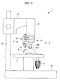
- Fig. 3 is a diagram illustrating a method for focus adjustment of the objective unit 5 and the stabilizer 7 in Fig. 1.
- the objective unit 5 and the stabilizer moving mechanism 33 are attached to, for example, an inverted microscope 500 before the focus adjustment of the objective unit 5 and the stabilizer moving mechanism 33.
- An indicator plate 71 with a cross mark, for example, is placed on top of the glass cover 43 of the end portion 39.
- the stabilizer body 31 is then moved along the optical-axis direction of the objective lens system 19 by rotating the knob of the microhead 63.
- the relative positions of the glass cover 43 on the end portion 39 and the objective lens system 19 are adjusted so that the focus (focal point) of the objective lens system 19 lies on the surface of the glass cover 43 in contact with the indicator plate 71, or the specimen A.
- Fig. 4 is a perspective view illustrating an examination method using the in vivo microscope system 1 in Fig. 1.
- a small laboratory animal is placed on the stage 3.
- the specimen A such as an organ
- the objective unit 5 and the stabilizer moving mechanism 33 are attached to the microscope body 9 after the completion of the focus adjustment, as shown in Fig. 1.
- the body male dovetail 57 fixed to the stabilizer moving mechanism 33 is fitted to the body female dovetail 53 fixed to the microscope body 9.
- the stabilizer moving mechanism 33 is attached to the microscope body 9 while being moved in a direction substantially perpendicular to the optical-axis direction of the microscope body 9. Accordingly, the objective unit 5 and the stabilizer moving mechanism 33 can be readily attached to the microscope body 9 with the small laboratory animal placed on the stage 3.
- the microscope body 9 is moved close to the small laboratory animal together with the stabilizer body 31 by operating the raising and lowering mechanism 17, as shown in Fig. 1.
- the end portion 39 of the stabilizer body 31 is moved close to the small laboratory animal and is pressed against the specimen A to suppress dynamic motion of the surface of the specimen A, as shown in Fig. 4.
- the pressing of the end portion 39 against the specimen A not only suppresses the dynamic motion of the specimen A, but also provides an in-focus observation image because the focus of the objective lens system 19 has been adjusted to the surface of the glass cover 43 in contact with the specimen A in advance.
- the stage 3 is moved in the X and Y directions by operating the adjustment dial 11 to move the specimen A in the X and Y directions, thus bringing a target examination region into the focus of the objective lens system 19.
- the glass cover 43 is attached to the end portion 39 as a pressing plate in the above embodiment
- the structure of the end portion 39 including the presence or absence of the glass cover 43 and the shape of the end portion 39, is not limited to the above embodiment.
- the manner of vibration suppression is not limited to simple pressing, and various approaches can of course be employed, including vibration suppression by suction through a suction hole defined in the end portion 39 using, for example, a suction pump.
- the objective lens system 19 can be readily replaced during examination because it can be attached to and detached from the stabilizer 7 in a direction crossing the optical-axis direction.
- the objective lens system 19 can be attached to and detached from the microscope body 9 and the stabilizer 7 by being moved in the direction crossing the optical-axis direction while a constant distance is maintained between the microscope body 9 and the specimen A. Because a constant distance is maintained between the microscope body 9 and the specimen A, the stabilizer 7 can continue to suppress vibrations in the examination region of the specimen A after the attachment/detachment of the objective lens system 19. In other words, the objective lens system 19 can be attached to and detached from the microscope body 9 and the stabilizer 7 during the examination while the stabilizer 7 is suppressing vibrations in the examination region of the specimen A.
- the stabilizer 7 can be readily detached from the microscope body 9 because the stabilizer 7 can be attached to and detached from the microscope body 9 in a direction crossing the optical-axis direction.
- the objective unit 5 and the stabilizer body 31 can be simultaneously attached to and detached from the microscope body 9 by attaching and detaching the stabilizer body 31 to and from the microscope body 9.
- the relative positions of the objective lens system 19 and the end portion 39 can therefore be adjusted while they have been detached from the microscope body 9.
- the objective unit 5 and the stabilizer body 31 can then be attached to the microscope body 9 with the adjusted relative positions thereof being maintained.
- the stabilizer moving mechanism 33 allows the focal point of the objective lens system 19 to be easily adjusted to the specimen A, where vibrations are suppressed by the end portion 39.
- the stabilizer moving mechanism 33 also allows easy WD adjustment.
- the end portion 39 is brought into contact with the examination region of the specimen A to suppress vibrations.
- the stabilizer moving mechanism 33 allows the focal point of the objective lens system 19 to be adjusted to the examination region, where vibrations are suppressed.
- the examination region, where vibrations are suppressed is always positioned at the surface of the end portion 39 in contact with the specimen A.
- the focal point can be readily adjusted to the examination region by adjusting the relative positions of the objective lens system 19 and the end portion 39 using the stabilizer moving mechanism 33 so that the focal point lies on the contact surface.
- the stabilizer moving mechanism 33 is detachably attached to the microscope body 9 and the end portion 39 is detachably attached to the stabilizer moving mechanism 33, the stabilizer moving mechanism 33 can be readily replaced. Also, the end portion 39 can be readily replaced by detaching only the end portion 39 from the stabilizer moving mechanism 33.
- the end portion 39 can be readily replaced because the end portion 39 is detachably attached to the stabilizer moving mechanism 33 in a direction crossing the optical-axis direction.
- the end portion 39 can be attached to and detached from the stabilizer moving mechanism 33 by being moved in the direction crossing the optical-axis direction. Accordingly, the end portion 39 can be readily replaced while a constant distance is maintained between the microscope body 9 and the specimen A.
- the specimen A can be readily examined because the stabilizer moving mechanism 33 is disposed between the microscope body 9 and the column 15.
- the stabilizer moving mechanism 33 is disposed between the microscope body 9 and the column 15, a large space can be left on the side of the microscope body 9 facing away from the column 15. Accordingly, the examiner can operate the in vivo microscope system 1 using the large space while the stabilizer moving mechanism 33 is kept out of the way. This facilitates the examination of the specimen A.
- Fig. 5 is a diagram showing another example of the objective lens system used for the in vivo microscope system 1 in Fig. 1.
- the type of objective lens system used is not limited to any particular type; it can be the objective lens system 19 shown in Fig. 1, as in the above embodiment, or, for example, a thinner objective lens system 19A with a shorter WD (stick-shaped objective lens) shown in Fig. 5.
- a notch-like opening 41A is preferably formed in the end portion 39 of the stabilizer body 31. The notch-like opening 41A allows detachment of the objective lens system 19 while preventing the front end of the objective lens system 19 from butting against the end portion 39.
- the position of the stabilizer moving mechanism 33 is not limited to any particular position, and it can be disposed between the microscope body 9 and the column 15, as in the above embodiment, or at any other position.
- An in vivo microscope system has the same basic structure as that according to the first embodiment except for the structure where the stabilizer moving mechanism is fixed to the microscope body. In this embodiment, therefore, only the vicinity of the structure where the stabilizer moving mechanism is fixed to the microscope body will be described with reference to Figs. 6 and 7, and no description will be given of the other components.
- Fig. 6 is a schematic diagram of the overall structure of the in vivo microscope system according to this embodiment.
- an in vivo microscope system (in vivo examination apparatus) 101 includes a stage 3 on which a specimen A is placed, an objective unit 5 facing the specimen A on the stage 3, a stabilizer (vibration suppressor) 107 for suppressing dynamic motion of the surface of the specimen A on the stage 3, and a microscope body 9 equipped with the objective unit 5 and the stabilizer 107.
- Fig. 7 is a diagram illustrating the structure of the objective unit 5 and the stabilizer 107 in Fig. 6.
- the stabilizer 107 includes a stabilizer body 31 and a stabilizer moving mechanism (moving part) 133.
- the stabilizer body 31 is attached to the microscope body 9 with the stabilizer moving mechanism 133 disposed therebetween.
- the stabilizer body 31 includes a mounting portion 35, an arm 37, and an end portion 39.
- the stabilizer moving mechanism 133 supports the stabilizer body 31 such that it can be moved along the optical-axis direction of the objective lens system 19 relative to the objective lens system 19.
- the stabilizer moving mechanism 133 is disposed between the microscope body 9 and the column 15.
- the stabilizer moving mechanism 133 includes a Z-stage 47, a moving mechanism plate 49, a stabilizer dovetail joint 51, and a body plate 159.
- the body plate 159 holds the objective female dovetail 23 and the Z-stage 47.
- the microscope body 9 is fixed to a surface of the body plate 159 opposite the microscope body 9 using screws, for example, and the objective female dovetail 23 is fixed to a surface of the body plate 159 opposite the objective unit 5 by the objective set screw 25.
- the Z-stage 47 is fixed to a side surface of the body plate 159. In other words, the microscope body 9 is fixed to the top surface of the body plate 159 perpendicular to the optical-axis direction of the objective unit 5, and the objective female dovetail 23 is fixed to the bottom surface of the body plate 159 perpendicular to the optical-axis direction of the objective unit 5.
- the Z-stage 47 is fixed to the side surface, parallel to the optical-axis direction, in a direction substantially perpendicular to the optical axis.
- the objective lens system 19 with a desired observation magnification is attached to the stabilizer moving mechanism 133 which is attached to the microscope body 9.
- the objective male dovetail 27 fixed to the objective lens system 19 is fitted into the objective female dovetail 23 fixed to the body plate 159 of the stabilizer moving mechanism 133.
- focal adjustment of the objective unit 5 and the stabilizer moving mechanism 133 is performed as in the first embodiment.
- a small laboratory animal is placed on the stage 3.
- the specimen A such as an organ, is exposed by making an incision in the skin C of the small laboratory animal (see Fig. 4).
- the microscope body 9 is then moved close to the small laboratory animal together with the stabilizer body 31 by operating the raising and lowering mechanism 17.
- the end portion 39 of the stabilizer body 31 is moved close to the small laboratory animal and is pressed against the specimen A (see Fig. 4) to suppress dynamic motion of the surface of the specimen A.
- the objective unit 5 can be readily replaced during examination because it can be attached to and detached from the stabilizer 107 in a direction crossing the optical-axis direction.
- the objective unit 5 can be attached and detached by being moved in the direction crossing the optical-axis direction while a constant distance is maintained between the microscope body 9 and the specimen A. Because a constant distance is maintained between the microscope body 9 and the specimen A, the stabilizer 107 can continue to suppress vibrations in the examination region of the specimen A after the attachment/detachment of the objective unit 5.
- the objective unit 5 can be attached to and detached from the microscope body 9 and the stabilizer 107 during the examination while the stabilizer 107 is suppressing vibrations in the examination region of the specimen A.
- An in vivo microscope system has the same basic structure as that according to the first embodiment except for the structure where the stabilizer moving mechanism is fixed to the microscope body. In this embodiment, therefore, only the vicinity of the structure where the stabilizer moving mechanism is fixed to the microscope body will be described with reference to Figs. 8 and 9, and no description will be given of the other components.
- Fig. 8 is a schematic diagram of the overall structure of the in vivo microscope system according to this embodiment.
- an in vivo microscope system (in vivo examination apparatus) 201 includes a stage 3 on which a specimen A is placed, an objective unit 5 facing the specimen A on the stage 3, a stabilizer (vibration suppressor) 207 for suppressing dynamic motion of the surface of the specimen A on the stage 3, and a microscope body 9 equipped with the objective unit 5 and the stabilizer 207.
- Fig. 9 is a diagram illustrating the structure of the objective unit 5 and the stabilizer 207 in Fig. 8.
- the stabilizer 207 includes a stabilizer body 31 and a stabilizer moving mechanism (moving part) 233.
- the stabilizer body 31 is attached to the microscope body 9 with the stabilizer moving mechanism 233 disposed therebetween.
- the stabilizer body 31 includes a mounting portion 35, an arm 37, and an end portion 39.
- the stabilizer moving mechanism 233 supports the stabilizer body 31 such that it can be moved along the optical-axis direction of the objective lens system 19 relative to the objective lens system 19.
- the stabilizer moving mechanism 233 is disposed between the microscope body 9 and the column 15.
- the stabilizer moving mechanism 233 includes a Z-stage 247, a moving mechanism plate 49, and a stabilizer dovetail joint 51.
- the Z-stage 247 allows the stabilizer 207 to be moved along the optical-axis direction of the objective lens system 19 relative to the objective lens system 19.
- the Z-stage 247 includes a fixed plate 261, a microhead 63, and a movable plate 65.
- the fixed plate 261 is fixed to the microscope body 9 using screws, for example, and is supported so that it can be moved relative to the movable plate 65.
- a cross roller guide (not shown) and the microhead 63 are disposed between the fixed plate 61 and the movable plate 65 so that the plates 61 and 65 can be moved relative to each other.
- the objective unit 5 can be readily replaced during examination because it can be attached to and detached from the microscope body 9 in a direction crossing the optical-axis direction.
- the objective unit 5 can be attached and detached by being moved in the direction crossing the optical-axis direction while a constant distance is maintained between the microscope body 9 and the specimen A. Because a constant distance is maintained between the microscope body 9 and the specimen A, the stabilizer 207 can continue to suppress vibrations in the examination region of the specimen A after the attachment/detachment of the objective unit 5.
- the objective unit 5 can be attached to and detached from the microscope body 9 during the examination while the stabilizer 207 is suppressing vibrations in the examination region of the specimen A.
Abstract
Description
- The present invention relates to in vivo examination apparatuses, and particularly to an in vivo examination apparatus including a stabilizer for allowing dynamic motion to be observed.
- This application is based on
Japanese Patent Application No. 2006-229720 - Visualization of ion concentration, membrane potential, and other properties by optical microscopy using fluorescent probes has recently been employed to examine, for example, biological functions of specimens such as nerve cells and organs, particularly to observe their dynamic motion.
- An example of a disclosed in vivo microscope system (in vivo examination apparatus) for observing dynamic motion has a stabilizer fitted and fixed to an outer cylindrical surface of a microscope objective unit (for example, see
Japanese Unexamined Patent Application, Publication No. 2005-338631 - The above in vivo microscope system, however, has the problem that the objective unit cannot be replaced during examination. Specifically, when the objective unit is replaced during examination, it alone cannot be replaced while suppressing vibrations at the examination site with the stabilizer, because the stabilizer is fixed to the cylindrical surface of the objective unit.
- The above in vivo microscope system also has the problem that replacement of the objective unit is burdensome. Specifically, the objective unit must be replaced together with the stabilizer because the stabilizer is fixed to the objective unit. This replacement is burdensome because it involves additional adjustments, including focus adjustment of an alternate objective unit and the stabilizer.
- An object of the present invention, which has been created to solve the above problems, is to provide an in vivo examination apparatus including an objective unit capable of being readily replaced during examination.
- To achieve the above object, the present invention provides the following solutions.
- The present invention provides an in vivo examination apparatus including a main body, a vibration suppressor configured to suppress vibrations in an examination region of an object under examination, and an objective optical system configured to observe the examination region where the vibrations are suppressed. The objective optical system and the vibration suppressor are attached to the main body. The objective optical system is attachable to and detachable from the main body in a direction crossing an optical-axis direction of the objective optical system.
- According to the present invention, the objective optical system can be readily replaced during examination because it can be attached to and detached from the main body in the direction crossing the optical-axis direction. The objective optical system can be attached and detached by being moved in the direction crossing the optical-axis direction while a constant distance is maintained between the main body and the object under examination. Because a constant distance is maintained between the main body and the object under examination, the vibration suppressor can continue to suppress vibrations in the examination region of the object under examination after the attachment/detachment of the objective optical system. In other words, the objective optical system can be attached to and detached from the main body during the examination while the vibration suppressor is suppressing vibrations in the examination region of the object under examination.
- In the present invention, preferably, the objective optical system is attached to the main body with the vibration suppressor disposed therebetween, the objective optical system is attachable to and detachable from the main body and the vibration suppressor in the direction crossing the optical-axis direction, and the vibration suppressor is attachable to and detachable from the main body.
- In this case, the vibration suppressor can continue to suppress vibrations in the examination region of the object under examination after the detachment of the objective optical system because the vibration suppressor is directly attached to the main body. The objective optical system and the vibration suppressor can be simultaneously attached to and detached from the main body by attaching and detaching the vibration suppressor to and from the main body. The relative positions of the objective optical system and the vibration suppressor can therefore be adjusted while they have been detached from the main body. The objective optical system and the vibration suppressor can then be attached to the main body with the adjusted relative positions thereof being maintained.
- In the above structure, the vibration suppressor is preferably attachable to and detachable from the main body in a direction crossing the optical-axis direction.
- In this case, the vibration suppressor can be readily detached from the main body without retracting the main body in the optical-axis direction.
- In the present invention, the vibration suppressor preferably includes a pressing part configured to suppress the vibrations in the examination region by coming into contact therewith and a moving part configured to support the pressing part movably in the optical-axis direction.
- In this case, the moving part of the vibration suppressor allows the focal point of the objective optical system to be easily adjusted to the object under examination, where vibrations are suppressed by the pressing part. The moving part also allows easy adjustment of working distance (hereinafter abbreviated as WD).
- The pressing part is brought into contact with the examination region of the object under examination to suppress vibrations. The moving part allows the focal point of the objective optical system to be adjusted to the examination region, where vibrations are suppressed. In other words, the examination region, where vibrations are suppressed, is always positioned at the surface of the pressing part in contact with the object under examination. The focal point can be readily adjusted to the examination region by adjusting the relative positions of the objective optical system and the pressing part using the moving part so that the focal point lies on the contact surface.
- In the present invention, preferably, the vibration suppressor includes a pressing part configured to suppress the vibrations in the examination region by coming into contact therewith and a moving part configured to support the pressing part movably in the optical-axis direction, and the pressing part is detachably attached to the moving part.
- In this case, the pressing part can be readily replaced by detaching only the pressing part from the moving part.
- In the present invention, preferably, the vibration suppressor includes a pressing part configured to suppress the vibrations in the examination region by coming into contact therewith and a moving part configured to support the pressing part movably in the optical-axis direction, the pressing part is detachably attached to the moving part, and the pressing part is attachable to and detachable from the moving part in a direction crossing the optical-axis direction.
- In this case, the pressing part can be readily replaced because the pressing part is detachably attached to the moving part in the direction crossing the optical-axis direction. The pressing part can be readily replaced while a constant distance is maintained between the main body and the object under examination.
- In the present invention, preferably, the vibration suppressor includes a pressing part configured to suppress the vibrations in the examination region by coming into contact therewith and a moving part configured to support the pressing part movably in the optical-axis direction, the in vivo examination apparatus further includes a column configured to support the main body, and the moving part is disposed between the main body and the column.
- In this case, a large space can be left on the side of the main body facing away from the column. Accordingly, the examiner can operate the in vivo examination apparatus using the large space while the moving part is kept out of the way. This facilitates the examination of the object under examination.
- The in vivo examination apparatus according to the present invention has the advantage that the objective optical system can be readily replaced during examination because the objective optical system and the vibration suppressor are attached to the main body and the objective optical system is attachable to and detachable from the main body in a direction crossing the optical-axis direction.
-
- Fig. 1 is a schematic diagram of the overall structure of an in vivo microscope system according to a first embodiment of the present invention;
- Fig. 2 is a diagram illustrating the structure of an objective unit and a stabilizer in Fig. 1;
- Fig. 3 is a diagram illustrating a method for focus adjustment of the objective unit and the stabilizer in Fig. 1;
- Fig. 4 is a perspective view illustrating an examination method using the in vivo microscope system in Fig. 1;
- Fig. 5 is a diagram showing another example of the objective lens system used for the in vivo microscope system in Fig. 1;
- Fig. 6 is a schematic diagram of the overall structure of an in vivo microscope system according to a second embodiment of the present invention;
- Fig. 7 is a diagram illustrating the structure of an objective unit and a stabilizer in Fig. 6;
- Fig. 8 is a schematic diagram of the overall structure of an in vivo microscope system according to a third embodiment of the present invention; and
- Fig. 9 is a diagram illustrating the structure of an objective unit and a stabilizer in Fig. 8.
- A first embodiment of the present invention will now be described with reference to Figs. 1 to 5.
- Fig. 1 is a schematic diagram of the overall structure of an in vivo microscope system according to this embodiment.
- An in vivo microscope system (in vivo examination apparatus) 1 according to this embodiment is designed to examine a specimen (object under examination) A. Examples of the specimen A include cells, biological tissue such as muscles, and a variety of organs such as hearts and livers of mammals typified by small laboratory animals.
- In Fig. 1, the in
vivo microscope system 1 includes astage 3 on which the specimen A is placed, an objective unit (objective optical system) 5 facing the specimen A on thestage 3, a stabilizer (vibration suppressor) 7 for suppressing dynamic motion of the surface of the specimen A on thestage 3, and a microscope body (main body) 9 equipped with theobjective unit 5 and thestabilizer 7. - The
stage 3 has anadjustment dial 11 for moving thestage 3 in two horizontal directions, for example, in the X and Y directions. Theadjustment dial 11 can be operated to move the specimen A on thestage 3 in the two horizontal directions, for example, in the X and Y directions. - The
microscope body 9 is attached to a column (support) 15 extending vertically from abase 13 with a raising andlowering mechanism 17 so that themicroscope body 9 can be moved vertically. Theobjective unit 5 and thestabilizer 7 are attached to themicroscope body 9. - The
objective unit 5 is attached to themicroscope body 9 so as to face vertically downward. The specimen A is placed on thestage 3, that is, between theobjective unit 5 and thestage 3, and can be observed through theobjective unit 5 positioned opposite the specimen A. Theobjective unit 5 includes anobjective lens system 19 and an objective dovetail joint 21. - The
objective lens system 19 is intended to observe the specimen A and is attached to an objectivemale dovetail 27 described below. - Fig. 2 is a diagram illustrating the structure of the
objective unit 5 and thestabilizer 7 in Fig. 1. - In Fig. 2, the objective dovetail joint 21 includes an objective
female dovetail 23, anobjective set screw 25, and the objectivemale dovetail 27. - The objective
female dovetail 23 and the objectivemale dovetail 27 constitute the objective dovetail joint 21. The objectivefemale dovetail 23 is fixed to abody plate 59 by the objective setscrew 25. - The
objective set screw 25 is screwed into a female screw thread formed in the body plate 59 (for example, a female screw thread according to Japanese Industrial Standards (JIS) B7141, entitled "Microscope -- Screw thread for objectives"; not shown) to fix the objectivefemale dovetail 23 to thebody plate 59. - The objective
male dovetail 27 and the objectivefemale dovetail 23 constitute the objective dovetail joint 21 such that the objectivemale dovetail 27 can be moved in a direction crossing the optical-axis direction of theobjective lens system 19, preferably, in a direction substantially perpendicular to the optical-axis direction of theobjective lens system 19. The objectivemale dovetail 27 has a female screw thread (according to JIS B7141, entitled "MicroscopeScrew thread for objectives"; not shown). Theobjective lens system 19 is attached to the objectivemale dovetail 27 by being screwed into the female screw thread. - The raising and lowering
mechanism 17 can raise and lower themicroscope body 9 to make theobjective unit 5 and thestabilizer 7 closer to and further away from the specimen A. That is, theobjective unit 5 can be moved close to and away from the specimen A for focusing. - In Fig. 2, the
stabilizer 7 includes astabilizer body 31 and a stabilizer moving mechanism (moving part) 33. Thestabilizer body 31 is attached to themicroscope body 9 with thestabilizer moving mechanism 33 disposed therebetween. Thestabilizer body 31 includes a mountingportion 35, anarm 37, and an end portion (pressing part) 39. - The mounting
portion 35 is a portion for attachment to thestabilizer moving mechanism 33. Theend portion 39 is a portion for pressing the surface of the specimen A to suppress its dynamic motion. Theend portion 39 extends in a direction crossing the optical-axis direction of theobjective lens system 19, preferably, in a direction substantially perpendicular to the optical-axis direction of theobjective lens system 19. Theend portion 39 has an opening 41 (see Fig. 4) through which the surface of the specimen A is observed with its dynamic motion being suppressed. Aglass cover 43 is disposed on a surface of theend portion 39 in contact with the specimen A so as to cover theopening 41. Thearm 37 joins the mountingportion 35 and theend portion 39 together. - When a small-animal specimen is observed, the
end portion 39 of thestabilizer 7 can be pressed against the surface of the specimen A to suppress its dynamic motion. The invivo microscope system 1 can thus provide a blur-free observation image of the surface of the specimen A. - In Fig. 1, the
stabilizer moving mechanism 33 supports thestabilizer body 31 such that it can be moved along the optical-axis direction of theobjective lens system 19 relative to theobjective lens system 19. Thestabilizer moving mechanism 33 is disposed between themicroscope body 9 and thecolumn 15. In Fig. 2, thestabilizer moving mechanism 33 includes a body dovetail joint 45, a Z-stage 47, a movingmechanism plate 49, and a stabilizer dovetail joint 51. - The body dovetail joint 45 supports the
stabilizer 7 and theobjective lens system 19 so that they can be attached to and detached from themicroscope body 9. The body dovetail joint 45 includes a bodyfemale dovetail 53, a body setscrew 55, abody male dovetail 57, and thebody plate 59. - The body
female dovetail 53 and thebody male dovetail 57 constitute the body dovetail joint 45. The bodyfemale dovetail 53 is fixed to themicroscope body 9 by the body setscrew 55. - The body set
screw 55 is screwed into a female screw thread formed in the microscope body 9 (for example, a female screw thread according to JIS B7141, entitled "MicroscopeScrew thread for objectives"; not shown) to fix the body female dovetail 53 to themicroscope body 9. - The body
female dovetail 53 and thebody male dovetail 57 constitute the body dovetail joint 45 such that thebody male dovetail 57 can be moved in a direction crossing the optical-axis direction of theobjective lens system 19, preferably, in a direction substantially perpendicular to the optical-axis direction of theobjective lens system 19. Thebody male dovetail 57 is fixed to thebody plate 59 using screws. - The
body plate 59 holds the objectivefemale dovetail 23, thebody male dovetail 57, and the Z-stage 47. Thebody male dovetail 57 is fixed to a surface of thebody plate 59 opposite themicroscope body 9, and the objectivefemale dovetail 23 is fixed to a surface of thebody plate 59 opposite theobjective unit 5. The Z-stage 47 is fixed to a side surface of thebody plate 59. In other words, thebody male dovetail 57 is fixed to the top surface of thebody plate 59 perpendicular to the optical-axis direction of theobjective unit 5, and the objectivefemale dovetail 23 is fixed to the bottom surface of thebody plate 59 perpendicular to the optical-axis direction of theobjective unit 5. The Z-stage 47 is fixed to the side surface, parallel to the optical-axis direction, in a direction substantially perpendicular to the optical axis. - The Z-
stage 47 allows thestabilizer 7 to be moved along the optical-axis direction of theobjective lens system 19 relative to theobjective lens system 19. The Z-stage 47 includes a fixedplate 61, amicrohead 63, and amovable plate 65. - The fixed
plate 61 is fixed to thebody plate 59 and is supported so that it can be moved relative to themovable plate 65. A cross roller guide (not shown) and themicrohead 63 are disposed between the fixedplate 61 and themovable plate 65 so that theplates - The
movable plate 65 can be moved relative to the fixedplate 61 by rotating a knob of themicrohead 63, which is fixed to the fixedplate 61. - The moving
mechanism plate 49 is fixed to themovable plate 65, which supports the movingmechanism plate 49 so that it can be moved relatively to the fixedplate 61. - The moving
mechanism plate 49 joins themovable plate 65 and the stabilizer dovetail joint 51 together. - The stabilizer dovetail joint 51 supports the
stabilizer body 31 so that it can be attached to and detached from thestabilizer moving mechanism 33. The stabilizer dovetail joint 51 includes a stabilizerfemale dovetail 67 and astabilizer male dovetail 69. - The stabilizer
female dovetail 67 and thestabilizer male dovetail 69 constitute the stabilizer dovetail joint 51. The stabilizerfemale dovetail 67 is fixed to the movingmechanism plate 49 using screws. - The stabilizer
female dovetail 67 and thestabilizer male dovetail 69 constitute the stabilizer dovetail joint 51 such that thestabilizer male dovetail 69 can be moved in a direction crossing the optical-axis direction of theobjective lens system 19, preferably, in a direction substantially perpendicular to the optical-axis direction of theobjective lens system 19. Thestabilizer male dovetail 69 is fixed to thestabilizer body 31 using screws. - The operation of the in
vivo microscope system 1 according to this embodiment will now be described. - First, the preparation procedure of the in
vivo microscope system 1 according to this embodiment will be described. - First, the
objective lens system 19 with a desired observation magnification is attached to thestabilizer moving mechanism 33 which is detached from themicroscope body 9. Specifically, the objectivemale dovetail 27 fixed to theobjective lens system 19 is fitted into the objectivefemale dovetail 23 fixed to thebody plate 59 of thestabilizer moving mechanism 33. - Fig. 3 is a diagram illustrating a method for focus adjustment of the
objective unit 5 and thestabilizer 7 in Fig. 1. - In Fig. 3, the
objective unit 5 and thestabilizer moving mechanism 33 are attached to, for example, aninverted microscope 500 before the focus adjustment of theobjective unit 5 and thestabilizer moving mechanism 33. - An
indicator plate 71 with a cross mark, for example, is placed on top of theglass cover 43 of theend portion 39. Thestabilizer body 31 is then moved along the optical-axis direction of theobjective lens system 19 by rotating the knob of themicrohead 63. The relative positions of theglass cover 43 on theend portion 39 and theobjective lens system 19 are adjusted so that the focus (focal point) of theobjective lens system 19 lies on the surface of theglass cover 43 in contact with theindicator plate 71, or the specimen A. - Fig. 4 is a perspective view illustrating an examination method using the in
vivo microscope system 1 in Fig. 1. - Next, a small laboratory animal is placed on the
stage 3. In Fig. 4, the specimen A, such as an organ, is exposed by making an incision in the skin C of the small laboratory animal. Theobjective unit 5 and thestabilizer moving mechanism 33 are attached to themicroscope body 9 after the completion of the focus adjustment, as shown in Fig. 1. Specifically, thebody male dovetail 57 fixed to thestabilizer moving mechanism 33 is fitted to the bodyfemale dovetail 53 fixed to themicroscope body 9. Thestabilizer moving mechanism 33 is attached to themicroscope body 9 while being moved in a direction substantially perpendicular to the optical-axis direction of themicroscope body 9. Accordingly, theobjective unit 5 and thestabilizer moving mechanism 33 can be readily attached to themicroscope body 9 with the small laboratory animal placed on thestage 3. - After the
objective unit 5 is attached to themicroscope body 9, themicroscope body 9 is moved close to the small laboratory animal together with thestabilizer body 31 by operating the raising and loweringmechanism 17, as shown in Fig. 1. Theend portion 39 of thestabilizer body 31 is moved close to the small laboratory animal and is pressed against the specimen A to suppress dynamic motion of the surface of the specimen A, as shown in Fig. 4. - The pressing of the
end portion 39 against the specimen A not only suppresses the dynamic motion of the specimen A, but also provides an in-focus observation image because the focus of theobjective lens system 19 has been adjusted to the surface of theglass cover 43 in contact with the specimen A in advance. - As shown in Fig. 1, the
stage 3 is moved in the X and Y directions by operating theadjustment dial 11 to move the specimen A in the X and Y directions, thus bringing a target examination region into the focus of theobjective lens system 19. - Although the
glass cover 43 is attached to theend portion 39 as a pressing plate in the above embodiment, the structure of theend portion 39, including the presence or absence of theglass cover 43 and the shape of theend portion 39, is not limited to the above embodiment. In addition, the manner of vibration suppression is not limited to simple pressing, and various approaches can of course be employed, including vibration suppression by suction through a suction hole defined in theend portion 39 using, for example, a suction pump. - With the above structure, the
objective lens system 19 can be readily replaced during examination because it can be attached to and detached from thestabilizer 7 in a direction crossing the optical-axis direction. - The
objective lens system 19 can be attached to and detached from themicroscope body 9 and thestabilizer 7 by being moved in the direction crossing the optical-axis direction while a constant distance is maintained between themicroscope body 9 and the specimen A. Because a constant distance is maintained between themicroscope body 9 and the specimen A, thestabilizer 7 can continue to suppress vibrations in the examination region of the specimen A after the attachment/detachment of theobjective lens system 19. In other words, theobjective lens system 19 can be attached to and detached from themicroscope body 9 and thestabilizer 7 during the examination while thestabilizer 7 is suppressing vibrations in the examination region of the specimen A. - The
stabilizer 7 can be readily detached from themicroscope body 9 because thestabilizer 7 can be attached to and detached from themicroscope body 9 in a direction crossing the optical-axis direction. - Because the
stabilizer 7 can be attached to and detached from themicroscope body 9 in the direction crossing the optical-axis direction, theobjective unit 5 and thestabilizer body 31 can be simultaneously attached to and detached from themicroscope body 9 by attaching and detaching thestabilizer body 31 to and from themicroscope body 9. The relative positions of theobjective lens system 19 and theend portion 39 can therefore be adjusted while they have been detached from themicroscope body 9. Theobjective unit 5 and thestabilizer body 31 can then be attached to themicroscope body 9 with the adjusted relative positions thereof being maintained. - The
stabilizer moving mechanism 33 allows the focal point of theobjective lens system 19 to be easily adjusted to the specimen A, where vibrations are suppressed by theend portion 39. Thestabilizer moving mechanism 33 also allows easy WD adjustment. - The
end portion 39 is brought into contact with the examination region of the specimen A to suppress vibrations. Thestabilizer moving mechanism 33 allows the focal point of theobjective lens system 19 to be adjusted to the examination region, where vibrations are suppressed. In other words, the examination region, where vibrations are suppressed, is always positioned at the surface of theend portion 39 in contact with the specimen A. The focal point can be readily adjusted to the examination region by adjusting the relative positions of theobjective lens system 19 and theend portion 39 using thestabilizer moving mechanism 33 so that the focal point lies on the contact surface. - Because the
stabilizer moving mechanism 33 is detachably attached to themicroscope body 9 and theend portion 39 is detachably attached to thestabilizer moving mechanism 33, thestabilizer moving mechanism 33 can be readily replaced. Also, theend portion 39 can be readily replaced by detaching only theend portion 39 from thestabilizer moving mechanism 33. - The
end portion 39 can be readily replaced because theend portion 39 is detachably attached to thestabilizer moving mechanism 33 in a direction crossing the optical-axis direction. - The
end portion 39 can be attached to and detached from thestabilizer moving mechanism 33 by being moved in the direction crossing the optical-axis direction. Accordingly, theend portion 39 can be readily replaced while a constant distance is maintained between themicroscope body 9 and the specimen A. - The specimen A can be readily examined because the
stabilizer moving mechanism 33 is disposed between themicroscope body 9 and thecolumn 15. - Because the
stabilizer moving mechanism 33 is disposed between themicroscope body 9 and thecolumn 15, a large space can be left on the side of themicroscope body 9 facing away from thecolumn 15. Accordingly, the examiner can operate the invivo microscope system 1 using the large space while thestabilizer moving mechanism 33 is kept out of the way. This facilitates the examination of the specimen A. - Fig. 5 is a diagram showing another example of the objective lens system used for the in
vivo microscope system 1 in Fig. 1. - The type of objective lens system used is not limited to any particular type; it can be the
objective lens system 19 shown in Fig. 1, as in the above embodiment, or, for example, a thinnerobjective lens system 19A with a shorter WD (stick-shaped objective lens) shown in Fig. 5. If theobjective lens system 19A is used, a notch-like opening 41A is preferably formed in theend portion 39 of thestabilizer body 31. The notch-like opening 41A allows detachment of theobjective lens system 19 while preventing the front end of theobjective lens system 19 from butting against theend portion 39. - The position of the
stabilizer moving mechanism 33 is not limited to any particular position, and it can be disposed between themicroscope body 9 and thecolumn 15, as in the above embodiment, or at any other position. - Next, a second embodiment of the present invention will be described with reference to Figs. 6 and 7.
- An in vivo microscope system according to this embodiment has the same basic structure as that according to the first embodiment except for the structure where the stabilizer moving mechanism is fixed to the microscope body. In this embodiment, therefore, only the vicinity of the structure where the stabilizer moving mechanism is fixed to the microscope body will be described with reference to Figs. 6 and 7, and no description will be given of the other components.
- Fig. 6 is a schematic diagram of the overall structure of the in vivo microscope system according to this embodiment.
- The same components as used in the first embodiment are indicated by the same reference numerals, and no description thereof will be given.
- In Fig. 6, an in vivo microscope system (in vivo examination apparatus) 101 includes a
stage 3 on which a specimen A is placed, anobjective unit 5 facing the specimen A on thestage 3, a stabilizer (vibration suppressor) 107 for suppressing dynamic motion of the surface of the specimen A on thestage 3, and amicroscope body 9 equipped with theobjective unit 5 and thestabilizer 107. - Fig. 7 is a diagram illustrating the structure of the
objective unit 5 and thestabilizer 107 in Fig. 6. - In Fig. 7, the
stabilizer 107 includes astabilizer body 31 and a stabilizer moving mechanism (moving part) 133. Thestabilizer body 31 is attached to themicroscope body 9 with thestabilizer moving mechanism 133 disposed therebetween. Thestabilizer body 31 includes a mountingportion 35, anarm 37, and anend portion 39. - In Fig. 7, the
stabilizer moving mechanism 133 supports thestabilizer body 31 such that it can be moved along the optical-axis direction of theobjective lens system 19 relative to theobjective lens system 19. Thestabilizer moving mechanism 133 is disposed between themicroscope body 9 and thecolumn 15. In Fig. 7, thestabilizer moving mechanism 133 includes a Z-stage 47, a movingmechanism plate 49, a stabilizer dovetail joint 51, and abody plate 159. - The
body plate 159 holds the objectivefemale dovetail 23 and the Z-stage 47. Themicroscope body 9 is fixed to a surface of thebody plate 159 opposite themicroscope body 9 using screws, for example, and the objectivefemale dovetail 23 is fixed to a surface of thebody plate 159 opposite theobjective unit 5 by the objective setscrew 25. The Z-stage 47 is fixed to a side surface of thebody plate 159. In other words, themicroscope body 9 is fixed to the top surface of thebody plate 159 perpendicular to the optical-axis direction of theobjective unit 5, and the objectivefemale dovetail 23 is fixed to the bottom surface of thebody plate 159 perpendicular to the optical-axis direction of theobjective unit 5. The Z-stage 47 is fixed to the side surface, parallel to the optical-axis direction, in a direction substantially perpendicular to the optical axis. - The operation of the in
vivo microscope system 101 according to this embodiment will now be described. - In Fig. 7, first, the
objective lens system 19 with a desired observation magnification is attached to thestabilizer moving mechanism 133 which is attached to themicroscope body 9. Specifically, the objectivemale dovetail 27 fixed to theobjective lens system 19 is fitted into the objectivefemale dovetail 23 fixed to thebody plate 159 of thestabilizer moving mechanism 133. Subsequently, focal adjustment of theobjective unit 5 and thestabilizer moving mechanism 133 is performed as in the first embodiment. - Next, a small laboratory animal is placed on the
stage 3. The specimen A, such as an organ, is exposed by making an incision in the skin C of the small laboratory animal (see Fig. 4). Themicroscope body 9 is then moved close to the small laboratory animal together with thestabilizer body 31 by operating the raising and loweringmechanism 17. Theend portion 39 of thestabilizer body 31 is moved close to the small laboratory animal and is pressed against the specimen A (see Fig. 4) to suppress dynamic motion of the surface of the specimen A. - With the above structure, the
objective unit 5 can be readily replaced during examination because it can be attached to and detached from thestabilizer 107 in a direction crossing the optical-axis direction. Theobjective unit 5 can be attached and detached by being moved in the direction crossing the optical-axis direction while a constant distance is maintained between themicroscope body 9 and the specimen A. Because a constant distance is maintained between themicroscope body 9 and the specimen A, thestabilizer 107 can continue to suppress vibrations in the examination region of the specimen A after the attachment/detachment of theobjective unit 5. In other words, theobjective unit 5 can be attached to and detached from themicroscope body 9 and thestabilizer 107 during the examination while thestabilizer 107 is suppressing vibrations in the examination region of the specimen A. - Next, a third embodiment of the present invention will be described with reference to Figs. 8 and 9.
- An in vivo microscope system according to this embodiment has the same basic structure as that according to the first embodiment except for the structure where the stabilizer moving mechanism is fixed to the microscope body. In this embodiment, therefore, only the vicinity of the structure where the stabilizer moving mechanism is fixed to the microscope body will be described with reference to Figs. 8 and 9, and no description will be given of the other components.
- Fig. 8 is a schematic diagram of the overall structure of the in vivo microscope system according to this embodiment.
- The same components as used in the first embodiment are indicated by the same reference numerals, and no description thereof will be given.
- In Fig. 8, an in vivo microscope system (in vivo examination apparatus) 201 includes a
stage 3 on which a specimen A is placed, anobjective unit 5 facing the specimen A on thestage 3, a stabilizer (vibration suppressor) 207 for suppressing dynamic motion of the surface of the specimen A on thestage 3, and amicroscope body 9 equipped with theobjective unit 5 and thestabilizer 207. - Fig. 9 is a diagram illustrating the structure of the
objective unit 5 and thestabilizer 207 in Fig. 8. - In Fig. 9, the
stabilizer 207 includes astabilizer body 31 and a stabilizer moving mechanism (moving part) 233. Thestabilizer body 31 is attached to themicroscope body 9 with thestabilizer moving mechanism 233 disposed therebetween. Thestabilizer body 31 includes a mountingportion 35, anarm 37, and anend portion 39. - In Fig. 8, the
stabilizer moving mechanism 233 supports thestabilizer body 31 such that it can be moved along the optical-axis direction of theobjective lens system 19 relative to theobjective lens system 19. Thestabilizer moving mechanism 233 is disposed between themicroscope body 9 and thecolumn 15. In Fig. 9, thestabilizer moving mechanism 233 includes a Z-stage 247, a movingmechanism plate 49, and a stabilizer dovetail joint 51. - The Z-
stage 247 allows thestabilizer 207 to be moved along the optical-axis direction of theobjective lens system 19 relative to theobjective lens system 19. The Z-stage 247 includes a fixedplate 261, amicrohead 63, and amovable plate 65. - The fixed
plate 261 is fixed to themicroscope body 9 using screws, for example, and is supported so that it can be moved relative to themovable plate 65. A cross roller guide (not shown) and themicrohead 63 are disposed between the fixedplate 61 and themovable plate 65 so that theplates - No description will be given of the operation of the in
vivo microscope system 201 according to this embodiment because the operation is similar to that of the invivo microscope system 101 according to the second embodiment. - With the above structure, the
objective unit 5 can be readily replaced during examination because it can be attached to and detached from themicroscope body 9 in a direction crossing the optical-axis direction. Theobjective unit 5 can be attached and detached by being moved in the direction crossing the optical-axis direction while a constant distance is maintained between themicroscope body 9 and the specimen A. Because a constant distance is maintained between themicroscope body 9 and the specimen A, thestabilizer 207 can continue to suppress vibrations in the examination region of the specimen A after the attachment/detachment of theobjective unit 5. In other words, theobjective unit 5 can be attached to and detached from themicroscope body 9 during the examination while thestabilizer 207 is suppressing vibrations in the examination region of the specimen A.
Claims (7)
- An in vivo examination apparatus comprising:a main body;a vibration suppressor configured to suppress vibrations in an examination region of an object under examination; andan objective optical system configured to observe the examination region where the vibrations are suppressed;wherein the objective optical system and the vibration suppressor are attached to the main body; and
the objective optical system is attachable to and detachable from the main body in a direction crossing an optical-axis direction of the objective optical system. - The in vivo examination apparatus according to Claim 1, wherein
the objective optical system is attached to the main body with the vibration suppressor disposed therebetween;
the objective optical system is attachable to and detachable from the main body and the vibration suppressor in the direction crossing the optical-axis direction; and
the vibration suppressor is attachable to and detachable from the main body. - The in vivo examination apparatus according to Claim 2, wherein the vibration suppressor is attachable to and detachable from the main body in a direction crossing the optical-axis direction.
- The in vivo examination apparatus according to one of claims 1 to 3, wherein the vibration suppressor comprises:a pressing part configured to suppress the vibrations in the examination region by coming into contact therewith; anda moving part configured to support the pressing part movably in the optical-axis direction.
- The in vivo examination apparatus according to Claim 4, wherein the pressing part is detachably attached to the moving part.
- The in vivo examination apparatus according to Claim 5, wherein the pressing part is attachable to and detachable from the moving part in a direction crossing the optical-axis direction.
- The in vivo examination apparatus according to one of claims 4 to 6, further comprising a column configured to support the main body, the moving part being disposed between the main body and the column.
Applications Claiming Priority (1)
| Application Number | Priority Date | Filing Date | Title |
|---|---|---|---|
| JP2006229720A JP4932384B2 (en) | 2006-08-25 | 2006-08-25 | Living body observation device |
Publications (2)
| Publication Number | Publication Date |
|---|---|
| EP1892552A1 true EP1892552A1 (en) | 2008-02-27 |
| EP1892552B1 EP1892552B1 (en) | 2009-12-23 |
Family
ID=38701484
Family Applications (1)
| Application Number | Title | Priority Date | Filing Date |
|---|---|---|---|
| EP07016354A Expired - Fee Related EP1892552B1 (en) | 2006-08-25 | 2007-08-21 | In vivo examination apparatus with a vibration suppressor |
Country Status (4)
| Country | Link |
|---|---|
| US (1) | US7675675B2 (en) |
| EP (1) | EP1892552B1 (en) |
| JP (1) | JP4932384B2 (en) |
| DE (1) | DE602007003909D1 (en) |
Cited By (1)
| Publication number | Priority date | Publication date | Assignee | Title |
|---|---|---|---|---|
| EP3133433B1 (en) * | 2014-12-29 | 2019-10-02 | Shanghai Ruiyu Biotech Co. Ltd. | Follow-up fixed focus system |
Families Citing this family (1)
| Publication number | Priority date | Publication date | Assignee | Title |
|---|---|---|---|---|
| JP6037732B2 (en) * | 2012-09-03 | 2016-12-07 | オリンパス株式会社 | Immersion holder, observation site fixing device, and microscope |
Citations (5)
| Publication number | Priority date | Publication date | Assignee | Title |
|---|---|---|---|---|
| EP0488023A1 (en) | 1990-11-19 | 1992-06-03 | Olympus Optical Co., Ltd. | Microscope having a focus-adjusting mechanism |
| WO1997041479A1 (en) * | 1996-04-26 | 1997-11-06 | Alpha Innotech Corporation | Anti-vibration stabilizer for a portable emission microscope |
| EP1186931A2 (en) | 2000-08-16 | 2002-03-13 | Leica Microsystems Heidelberg GmbH | Vibration damping device for microscopes and microscope with a vibration damping device |
| US6437911B1 (en) | 1999-09-16 | 2002-08-20 | Olympus Optical Co., Ltd. | Objective changing-over apparatus |
| US20040036962A1 (en) | 2002-01-28 | 2004-02-26 | Carl Zeiss Jena Gmbh | Microscope, in particular for surgery |
Family Cites Families (8)
| Publication number | Priority date | Publication date | Assignee | Title |
|---|---|---|---|---|
| JP3537194B2 (en) * | 1994-10-17 | 2004-06-14 | オリンパス株式会社 | Light microscope |
| US5793524A (en) * | 1997-08-04 | 1998-08-11 | Luloh; K. Peter | Device for non-contact wide-angle viewing of fundus during vitrectomy |
| US6392795B2 (en) * | 1998-08-28 | 2002-05-21 | Olympus Optical Co., Ltd. | Microscope with a dynamic damper |
| US6496308B2 (en) * | 2000-06-13 | 2002-12-17 | Olympus Optical Co., Ltd. | Relay optical system |
| JP4704758B2 (en) * | 2005-01-11 | 2011-06-22 | オリンパス株式会社 | Microscope observation system |
| US20050280892A1 (en) * | 2004-05-28 | 2005-12-22 | Nobuyuki Nagasawa | Examination method and examination apparatus |
| JP4624725B2 (en) * | 2004-05-28 | 2011-02-02 | オリンパス株式会社 | Microscope observation system and microscope observation method |
| JP2006145771A (en) * | 2004-11-18 | 2006-06-08 | Olympus Corp | Microscope objective, microscope and electric insulating member |
-
2006
- 2006-08-25 JP JP2006229720A patent/JP4932384B2/en not_active Expired - Fee Related
-
2007
- 2007-08-21 DE DE602007003909T patent/DE602007003909D1/en active Active
- 2007-08-21 US US11/842,561 patent/US7675675B2/en active Active
- 2007-08-21 EP EP07016354A patent/EP1892552B1/en not_active Expired - Fee Related
Patent Citations (5)
| Publication number | Priority date | Publication date | Assignee | Title |
|---|---|---|---|---|
| EP0488023A1 (en) | 1990-11-19 | 1992-06-03 | Olympus Optical Co., Ltd. | Microscope having a focus-adjusting mechanism |
| WO1997041479A1 (en) * | 1996-04-26 | 1997-11-06 | Alpha Innotech Corporation | Anti-vibration stabilizer for a portable emission microscope |
| US6437911B1 (en) | 1999-09-16 | 2002-08-20 | Olympus Optical Co., Ltd. | Objective changing-over apparatus |
| EP1186931A2 (en) | 2000-08-16 | 2002-03-13 | Leica Microsystems Heidelberg GmbH | Vibration damping device for microscopes and microscope with a vibration damping device |
| US20040036962A1 (en) | 2002-01-28 | 2004-02-26 | Carl Zeiss Jena Gmbh | Microscope, in particular for surgery |
Cited By (1)
| Publication number | Priority date | Publication date | Assignee | Title |
|---|---|---|---|---|
| EP3133433B1 (en) * | 2014-12-29 | 2019-10-02 | Shanghai Ruiyu Biotech Co. Ltd. | Follow-up fixed focus system |
Also Published As
| Publication number | Publication date |
|---|---|
| US7675675B2 (en) | 2010-03-09 |
| EP1892552B1 (en) | 2009-12-23 |
| DE602007003909D1 (en) | 2010-02-04 |
| JP4932384B2 (en) | 2012-05-16 |
| US20080174859A1 (en) | 2008-07-24 |
| JP2008052138A (en) | 2008-03-06 |
Similar Documents
| Publication | Publication Date | Title |
|---|---|---|
| US7903327B2 (en) | Fluorescence microscope apparatus | |
| JP6037732B2 (en) | Immersion holder, observation site fixing device, and microscope | |
| US20050280892A1 (en) | Examination method and examination apparatus | |
| EP1524542B1 (en) | Objective lens insertion tool & objective optical system attachment device | |
| JP6280770B2 (en) | measuring device | |
| US7675675B2 (en) | In vivo examination apparatus | |
| JP2008043771A (en) | Attachment module for fundus examination and operation microscope with it | |
| JP2005338631A (en) | Microscopic observation system and microscopic observation method | |
| EP1757969A1 (en) | Microscope moving unit and microscope apparatus | |
| US20040223213A1 (en) | Microscopic observing apparatus and probe microscope | |
| KR20180034815A (en) | Three dimensional confocal scanning needle probe | |
| JP2005234306A (en) | Microscopic observing apparatus | |
| US8405903B2 (en) | Objective-optical-system positioning apparatus and examination apparatus | |
| CN1834719A (en) | Microscope for operation | |
| JP4043991B2 (en) | Microscope observation apparatus and probe type microscope | |
| JP6978592B2 (en) | Dynamic focus zoom system for wide-area confocal and multiphoton microscopy | |
| JP3365803B2 (en) | Microscope focusing device | |
| EP1808720B1 (en) | Examination apparatus | |
| EP1843188A1 (en) | Stabilizer for in vivo examination | |
| DE202005009189U1 (en) | Arrangement for conducting con-focal laser-scanning contact endoscopy in larger cavity of body, using water immersion lens | |
| JP4996973B2 (en) | Stabilizer and biological observation apparatus | |
| CN219349259U (en) | Multifunctional adapter for live animal window microscopic imaging | |
| CN211610865U (en) | Real-time microscopic sterilization system | |
| JP4054419B2 (en) | microscope | |
| KR20220099128A (en) | Suction type stabilizer for objective lens and medical microscope and medical endoscope including the same |
Legal Events
| Date | Code | Title | Description |
|---|---|---|---|
| PUAI | Public reference made under article 153(3) epc to a published international application that has entered the european phase |
Free format text: ORIGINAL CODE: 0009012 |
|
| AK | Designated contracting states |
Kind code of ref document: A1 Designated state(s): AT BE BG CH CY CZ DE DK EE ES FI FR GB GR HU IE IS IT LI LT LU LV MC MT NL PL PT RO SE SI SK TR |
|
| AX | Request for extension of the european patent |
Extension state: AL BA HR MK YU |
|
| 17P | Request for examination filed |
Effective date: 20080516 |
|
| 17Q | First examination report despatched |
Effective date: 20080619 |
|
| AKX | Designation fees paid |
Designated state(s): DE FR GB |
|
| RTI1 | Title (correction) |
Free format text: IN VIVO EXAMINATION APPARATUS WITH A VIBRATION SUPPRESSOR |
|
| GRAP | Despatch of communication of intention to grant a patent |
Free format text: ORIGINAL CODE: EPIDOSNIGR1 |
|
| GRAS | Grant fee paid |
Free format text: ORIGINAL CODE: EPIDOSNIGR3 |
|
| GRAA | (expected) grant |
Free format text: ORIGINAL CODE: 0009210 |
|
| AK | Designated contracting states |
Kind code of ref document: B1 Designated state(s): DE FR GB |
|
| REG | Reference to a national code |
Ref country code: GB Ref legal event code: FG4D |
|
| REF | Corresponds to: |
Ref document number: 602007003909 Country of ref document: DE Date of ref document: 20100204 Kind code of ref document: P |
|
| PLBE | No opposition filed within time limit |
Free format text: ORIGINAL CODE: 0009261 |
|
| STAA | Information on the status of an ep patent application or granted ep patent |
Free format text: STATUS: NO OPPOSITION FILED WITHIN TIME LIMIT |
|
| 26N | No opposition filed |
Effective date: 20100924 |
|
| REG | Reference to a national code |
Ref country code: FR Ref legal event code: ST Effective date: 20110502 |
|
| PG25 | Lapsed in a contracting state [announced via postgrant information from national office to epo] |
Ref country code: FR Free format text: LAPSE BECAUSE OF NON-PAYMENT OF DUE FEES Effective date: 20100831 |
|
| GBPC | Gb: european patent ceased through non-payment of renewal fee |
Effective date: 20110821 |
|
| PG25 | Lapsed in a contracting state [announced via postgrant information from national office to epo] |
Ref country code: GB Free format text: LAPSE BECAUSE OF NON-PAYMENT OF DUE FEES Effective date: 20110821 |
|
| PGFP | Annual fee paid to national office [announced via postgrant information from national office to epo] |
Ref country code: DE Payment date: 20170815 Year of fee payment: 11 |
|
| REG | Reference to a national code |
Ref country code: DE Ref legal event code: R119 Ref document number: 602007003909 Country of ref document: DE |
|
| PG25 | Lapsed in a contracting state [announced via postgrant information from national office to epo] |
Ref country code: DE Free format text: LAPSE BECAUSE OF NON-PAYMENT OF DUE FEES Effective date: 20190301 |