EP1892438B1 - Control of the travel direction of a vehicle - Google Patents
Control of the travel direction of a vehicle Download PDFInfo
- Publication number
- EP1892438B1 EP1892438B1 EP20060119216 EP06119216A EP1892438B1 EP 1892438 B1 EP1892438 B1 EP 1892438B1 EP 20060119216 EP20060119216 EP 20060119216 EP 06119216 A EP06119216 A EP 06119216A EP 1892438 B1 EP1892438 B1 EP 1892438B1
- Authority
- EP
- European Patent Office
- Prior art keywords
- vehicle
- inclination
- detector
- speed
- reverse
- Prior art date
- Legal status (The legal status is an assumption and is not a legal conclusion. Google has not performed a legal analysis and makes no representation as to the accuracy of the status listed.)
- Expired - Fee Related
Links
Images


Classifications
-
- F—MECHANICAL ENGINEERING; LIGHTING; HEATING; WEAPONS; BLASTING
- F16—ENGINEERING ELEMENTS AND UNITS; GENERAL MEASURES FOR PRODUCING AND MAINTAINING EFFECTIVE FUNCTIONING OF MACHINES OR INSTALLATIONS; THERMAL INSULATION IN GENERAL
- F16H—GEARING
- F16H59/00—Control inputs to control units of change-speed-, or reversing-gearings for conveying rotary motion
- F16H59/36—Inputs being a function of speed
- F16H59/44—Inputs being a function of speed dependent on machine speed of the machine, e.g. the vehicle
-
- F—MECHANICAL ENGINEERING; LIGHTING; HEATING; WEAPONS; BLASTING
- F16—ENGINEERING ELEMENTS AND UNITS; GENERAL MEASURES FOR PRODUCING AND MAINTAINING EFFECTIVE FUNCTIONING OF MACHINES OR INSTALLATIONS; THERMAL INSULATION IN GENERAL
- F16H—GEARING
- F16H61/00—Control functions within control units of change-speed- or reversing-gearings for conveying rotary motion ; Control of exclusively fluid gearing, friction gearing, gearings with endless flexible members or other particular types of gearing
- F16H61/12—Detecting malfunction or potential malfunction, e.g. fail safe; Circumventing or fixing failures
-
- F—MECHANICAL ENGINEERING; LIGHTING; HEATING; WEAPONS; BLASTING
- F16—ENGINEERING ELEMENTS AND UNITS; GENERAL MEASURES FOR PRODUCING AND MAINTAINING EFFECTIVE FUNCTIONING OF MACHINES OR INSTALLATIONS; THERMAL INSULATION IN GENERAL
- F16H—GEARING
- F16H59/00—Control inputs to control units of change-speed-, or reversing-gearings for conveying rotary motion
- F16H59/36—Inputs being a function of speed
- F16H59/44—Inputs being a function of speed dependent on machine speed of the machine, e.g. the vehicle
- F16H2059/443—Detecting travel direction, e.g. the forward or reverse movement of the vehicle
-
- F—MECHANICAL ENGINEERING; LIGHTING; HEATING; WEAPONS; BLASTING
- F16—ENGINEERING ELEMENTS AND UNITS; GENERAL MEASURES FOR PRODUCING AND MAINTAINING EFFECTIVE FUNCTIONING OF MACHINES OR INSTALLATIONS; THERMAL INSULATION IN GENERAL
- F16H—GEARING
- F16H59/00—Control inputs to control units of change-speed-, or reversing-gearings for conveying rotary motion
- F16H59/60—Inputs being a function of ambient conditions
- F16H59/66—Road conditions, e.g. slope, slippery
- F16H2059/663—Road slope
-
- F—MECHANICAL ENGINEERING; LIGHTING; HEATING; WEAPONS; BLASTING
- F16—ENGINEERING ELEMENTS AND UNITS; GENERAL MEASURES FOR PRODUCING AND MAINTAINING EFFECTIVE FUNCTIONING OF MACHINES OR INSTALLATIONS; THERMAL INSULATION IN GENERAL
- F16H—GEARING
- F16H61/00—Control functions within control units of change-speed- or reversing-gearings for conveying rotary motion ; Control of exclusively fluid gearing, friction gearing, gearings with endless flexible members or other particular types of gearing
- F16H61/12—Detecting malfunction or potential malfunction, e.g. fail safe; Circumventing or fixing failures
- F16H2061/1208—Detecting malfunction or potential malfunction, e.g. fail safe; Circumventing or fixing failures with diagnostic check cycles; Monitoring of failures
-
- F—MECHANICAL ENGINEERING; LIGHTING; HEATING; WEAPONS; BLASTING
- F16—ENGINEERING ELEMENTS AND UNITS; GENERAL MEASURES FOR PRODUCING AND MAINTAINING EFFECTIVE FUNCTIONING OF MACHINES OR INSTALLATIONS; THERMAL INSULATION IN GENERAL
- F16H—GEARING
- F16H61/00—Control functions within control units of change-speed- or reversing-gearings for conveying rotary motion ; Control of exclusively fluid gearing, friction gearing, gearings with endless flexible members or other particular types of gearing
- F16H61/12—Detecting malfunction or potential malfunction, e.g. fail safe; Circumventing or fixing failures
- F16H2061/1256—Detecting malfunction or potential malfunction, e.g. fail safe; Circumventing or fixing failures characterised by the parts or units where malfunctioning was assumed or detected
- F16H2061/1284—Detecting malfunction or potential malfunction, e.g. fail safe; Circumventing or fixing failures characterised by the parts or units where malfunctioning was assumed or detected the failing part is a sensor
-
- F—MECHANICAL ENGINEERING; LIGHTING; HEATING; WEAPONS; BLASTING
- F16—ENGINEERING ELEMENTS AND UNITS; GENERAL MEASURES FOR PRODUCING AND MAINTAINING EFFECTIVE FUNCTIONING OF MACHINES OR INSTALLATIONS; THERMAL INSULATION IN GENERAL
- F16H—GEARING
- F16H2312/00—Driving activities
- F16H2312/02—Driving off
-
- F—MECHANICAL ENGINEERING; LIGHTING; HEATING; WEAPONS; BLASTING
- F16—ENGINEERING ELEMENTS AND UNITS; GENERAL MEASURES FOR PRODUCING AND MAINTAINING EFFECTIVE FUNCTIONING OF MACHINES OR INSTALLATIONS; THERMAL INSULATION IN GENERAL
- F16H—GEARING
- F16H59/00—Control inputs to control units of change-speed-, or reversing-gearings for conveying rotary motion
- F16H59/60—Inputs being a function of ambient conditions
- F16H59/66—Road conditions, e.g. slope, slippery
Definitions
- the present invention relates to a method for checking a reverse-speed detector or switch.
- the reverse gear switch mounted on the transmission or the shift gate has heretofore been used to activate a reversing light when the reverse gear is engaged.
- a malfunction of the switch and thus the reversing light was therefore comparatively unproblematic.
- the associated electronic evaluation unit With increasing, usually electronically controlled driving assistance of the driver, it is of increasing importance for the associated electronic evaluation unit to obtain information and, above all, reliable information about whether a reverse gear is engaged or not.
- the reliability of the information as to whether a reverse gear is actually engaged, especially when solving an electronic parking aid and a slope traction help is crucial and can cause disastrous damage to personal injury to a wrong signal. This is absolutely to be avoided.
- a redundant design of the reverse switch is usually out of space and material costs out of the question.
- this method completely disregards the problem of checking on non-level ground and further that in general the longitudinal acceleration sensor is attached to the body and that with the release of the brake in a hanging length, the spring-mounted body of the car realigns, and the The resulting longitudinal acceleration can affect the result of the longitudinal acceleration sensor and thus significantly affect the implementation of the process, if not distort it. Furthermore, no plausibility check is provided in the disclosed method.
- the method according to the invention serves to check (verify) the operability of a reverse gear detector of a vehicle which detects an engaged reverse gear, by evaluating the bodywork movement relative to the chassis in a relevant starting situation.
- the detector is, for example, an am Transmission or switch attached to the circuit board, which is actuated when the reverse gear is engaged.
- a signal of the reverse-speed detector which indicates that the reverse gear is engaged or not, is detected in a relevant starting situation.
- a relevant starting situation is identified by the fact that the speed of the vehicle is detected by means of a speed sensor and that this (the speed) is in an interval from standstill to a predetermined speed of the vehicle.
- the predetermined speed value is determined empirically and vehicle-dependent. However, it has surprisingly been found in several experiments that an upper limit of 2km / h and thus such a definition of the starting range is particularly suitable to ensure reliable and cross-vehicle monitoring.
- the temporal course of the inclination of the body of the vehicle relative to the chassis ie the so-called aestheticwegung the body relative to the chassis detected and summed up or integrated in the relevant Anfahrsituation ie in the interval from standstill to the predetermined speed. It is up to the skilled person to select a suitable sampling rate for the determination of the measured values over time.
- the obtained value of the integration or summation is at least evaluated according to the sign and optionally with a predetermined value comparative. It will be apparent to those skilled in the art that depending on the direction of longitudinal acceleration, ie forward or backward acceleration, there will be another sign of acceleration, the determination of what is positive or negative is merely a matter of convention.
- the optional comparison value is generally specified vehicle or chassis-specific.
- a presence or absence of a backward situation is identified by For example, it is checked whether an expected sign of the signal of the longitudinal acceleration sensor and / or the predetermined value is exceeded or fallen below. This identification result is compared with the signal from the reverse detector and, in the event of a discrepancy, an error is output and / or stored as a result of the comparison.
- the method is characterized in that compared to the prior art, a simple and comparatively simple means, ie sensors, a check of the functioning of the reverse-speed detector takes place. In addition, the process has proven to be particularly reliable.
- a relevant starting situation is then additionally identified by the fact that a level alignment of the vehicle is present at standstill.
- a relevant starting situation exists when, in addition to the condition that the speed is in the range of the standstill to the predetermined speed value, the condition is satisfied that a level orientation of the vehicle is determined at standstill by means of a tilt sensor. It has been shown in several experiments that then preferably a plane orientation is present when the determined by the inclination sensor inclination of the vehicle is in the range between -2% and 2%.
- the reliability of the method according to the invention can be increased, otherwise at a tilt of the vehicle at a standstill caused by the longitudinal acceleration in certain situations, such as by opposing effects, such as the subsequent alignment process, so minimal that it can not be evaluated.
- the accuracy and reliability of the method according to the invention are additionally increased.
- the aforementioned tilt sensor is a longitudinal acceleration sensor.
- the sensor technology for carrying out the method according to the invention can advantageously be reduced become.
- such sensors are used in four-wheel drive vehicles.
- a relevant Anfahrsituation is additionally identified by the fact that the reverse detector signals an engaged reverse and the inclination sensor or the longitudinal acceleration sensor signals a sloping forward of the vehicle inclination of the vehicle or that the reverse detector signaled no reverse gear engaged and the inclination sensor or the longitudinal acceleration sensor signals an inclination of the vehicle increasing in the forward direction of the vehicle.
- a starting situation is considered relevant only and should be checked when the vehicle at a standstill inclined upward and the detector indicates no reverse or when the vehicle is inclined sloping forward and the vehicle according to the detector
- Reverse engagement has the reliability of the method according to the invention can also be increased, since just such Anfahrsituation are not considered relevant in which the inclination of the vehicle at standstill, the longitudinal acceleration caused by the start so restrict or influence that it is so unimagined that they not or only badly detected by the sensor or can be evaluated thereafter.
- the accuracy and reliability of the method according to the invention are additionally increased.
- the speed is evaluated in an advantageous embodiment by means of a direction-insensitive speed sensor. Since non-directional speed sensors are much cheaper and are generally used to generate the speedometer signal and thus belong to the basic equipment of a vehicle, the inventive method can be realized inexpensively.
- a braking effect of the vehicle is detected by means of a sensor, and the measured value of the longitudinal acceleration is determined only after the braking effect has been discontinued and an alignment or transient caused thereby has ended.
- This is preferably considered only in a tilted orientation of the vehicle, d. H. only when an inclination of the vehicle is detected.
- the braking effect is monitored, for example, by means of a brake pressure sensor or a brake pedal switch. The effect of the accuracy and reliability of the inventive method affecting alignment or transient process can thus be eliminated in the determination of the essential for the assessment of the detector slope pattern.
- the inclination is determined at standstill, preferably after the alignment or transient process, and used as an offset value for approximate determination of the inclination of the body relative to the chassis of the vehicle, ie the inclination of the vehicle is compared to the body movement before the body movement determined by the chassis in order to maintain the inclination of the roadway.
- the measured inclination is corrected by this offset value, so as to approximately determine the inclination between the body and the chassis.
- the alignment and transient is considered after an empirically determined timing, for example, of 200 ms, after the release of the brake for completed and determined at this time, the offset value.
- the offset value can be detected and averaged in a corresponding time interval after completion of the transient process and before the onset of the body movement, the limits being empirically determined vehicle-specific.
- a plurality of relevant starting situations are evaluated for falsification, and an error is output and / or stored only when a predetermined frequency of the discrepancy is exceeded when comparing the signal of the detector and the determined presence or absence of a reverse situation.
- This can increase the reliability of the monitoring. It is the person skilled in the art to specify the number of times required for an error output on the basis of safety-relevant aspects.
- the error possibly with the frequency of the discrepancy, can be stored in a non-volatile memory, which retains its contents even after switching off the ignition and disconnecting the battery of the vehicle.
- the number with which the discrepancy has occurred is always reduced by one if there is a match between the signal of the detector and the result of the evaluation, i. H. to a confirmation of the function of the detector, has come.
- the invention further relates to a device for checking the operability of a, an inserted reverse gear detecting reverse gear detector with an evaluation unit.
- the evaluation unit is able to carry out the method in the previously described embodiments and the associated advantages.
- the invention relates to a vehicle with a speed sensor, a tilt sensor or longitudinal acceleration sensor and a device with an evaluation unit for carrying out the method described above.
- the speed sensor is preferably a direction-insensitive speed sensor.
- a sensor for monitoring the braking effect can be provided for the reasons explained above; it is preferably a brake pressure sensor or a brake pedal switch.
- the vehicle described above is preferably a vehicle with an electronic parking aid and / or a slope traction aid.
- the method according to the invention is of great advantage, since the evaluation unit, which is connected in each case with the aforementioned driving supports, receives one of the required information from the reverse gear detector. Thus, their proper function is only ensured if this detector works reliably. As described above, the function of the detector can be monitored very reliably by the method according to the invention.
- an error output by the method according to the invention can be used to switch the aforementioned driving support into an emergency operation in order to reduce the risk to persons in the event of failure of the reverse gear detector by a malfunction of the respective driving support.
- the reference numeral 1 corresponds to the time course of the signal of the speed sensor
- the reference numeral 2 the time course of the signal of the brake pressure sensor
- the reference numeral 3 the time course of the signal of the clutch position sensor
- the reference numeral 4 the time course of the signal of the accelerator pedal position sensor
- the reference numeral 5 the time course of the signal of the tilt sensor.
- the diagram of FIG. 1 describes the situation that a backward directed approach situation on flat road (amount of the slope less than 2%) is made.
- the integral A1 assumes a value below a negative limit and the slope remains negative up to a speed of 2km / h.
- the relevant starting situation is indicated by the integral A1. If the reverse gear detector signal is correct, its function is confirmed, otherwise an error is output.
- the diagram of FIG. 2 describes the situation that a forward-facing approach situation on flat road (amount of the slope less than 2%) is made.
- the Intergral A2 takes a value above a positive limit and the slope remains positive up to a speed of 2km / h.
- the relevant starting situation is indicated by the integral A2. If the reverse gear detector signal is correct, its function is confirmed, otherwise an error is output.
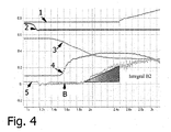
- the diagrams of Figures 3 and 4 describe two more start-up situations that are considered relevant for efficient monitoring.
- the diagram of FIG. 3 Namely, the situation shows that there is a downhill in the forward direction of the vehicle (-5%) and the reverse gear is engaged. That is, in this situation, it is checked whether the (positive) signal of the detector coincides with the expected measurement results. After release of the brake (strong drop in the course of the signal 2), after completion of the transient process, which is not taken into account, a course is detected with an almost constant course of the inclination in the region A. This area can be used to determine from the measured slope value, the inclination of the chassis or the roadway due to the subsequent later body movement of the body and the completed transient.
- the value (here the -5%) is determined in about 200 ms after the release of the brake and is used as the offset value in the further determination of the slope in order to calculate the approximate (relative) from the measured slope value by correction by the offset value. Tilt between the body and the chassis to get. With the beginning of the actual body movement between chassis and chassis, the inclination drops sharply.
- the integral B1 of the slope over the time from when the offset value was determined to the time when the speed of the vehicle is 2km / h is calculated.
- the integral B1 is below a negative limit and remains negative.
- the value in this case the + 5% is determined in about 200 ms after release of the brake and is used as an offset value in the further determination of the slope in order to calculate the approximate (relative) from the measured slope value by correction by the offset value.
- the integral B2 of the slope over the time from the time when the offset value was determined to the time when the speed of the vehicle is 2km / h is calculated.
- the integral B2 is above a positive limit and remains positive. Thus, the signal of the detector that no reverse gear is engaged, its function can be confirmed. If there is a discrepancy, an error is output.
Abstract
Description
Die vorliegende Erfindung betrifft ein Verfahren zur Überprüfung eines Rückwärtsgang-Detektors bzw. -Schalters.The present invention relates to a method for checking a reverse-speed detector or switch.
Im Allgemeinen wurde bisher der am Getriebe oder der Schaltkulisse angebrachte Rückwärtsgangschalter dazu benutzt, bei Einlegen des Rückwärtsgangs einen Rückfahrscheinwerfer zu aktivieren. Eine Fehlfunktion des Schalters und damit des Rückfahrscheinwerfers war daher bisher vergleichsweise unproblematisch. Mit zunehmender, meist elektronisch geregelter Fahrunterstützung des Fahrers ist es für die damit verbundene elektronische Auswerteinheit von immer größerer Bedeutung, eine Information und vor Allem eine zuverlässige Information darüber zu erhalten, ob ein Rückwärtsgang eingelegt ist oder nicht. Beispielsweise ist die Zuverlässigkeit der Information, ob tatsächlich ein Rückwärtsgang eingelegt ist, insbesondere beim Lösen einer elektronischen Parkhilfe und einer Hang-Anfahrhilfe von entscheidender Bedeutung und kann bei einem falschen Signal verheerende Schäden bis Personenschäden auslösen. Dies ist unbedingt zu vermeiden. Ein redundanter Aufbau des Rückwärtsgangschalters kommt meist aus Platz- und Materialkosten nicht in Frage.In general, the reverse gear switch mounted on the transmission or the shift gate has heretofore been used to activate a reversing light when the reverse gear is engaged. A malfunction of the switch and thus the reversing light was therefore comparatively unproblematic. With increasing, usually electronically controlled driving assistance of the driver, it is of increasing importance for the associated electronic evaluation unit to obtain information and, above all, reliable information about whether a reverse gear is engaged or not. For example, the reliability of the information as to whether a reverse gear is actually engaged, especially when solving an electronic parking aid and a slope traction help is crucial and can cause disastrous damage to personal injury to a wrong signal. This is absolutely to be avoided. A redundant design of the reverse switch is usually out of space and material costs out of the question.
So wird in der
Vor dem zuvor beschriebenen Stand der Technik ist es Aufgabe der vorliegenden Erfindung, ein verbessertes und vergleichsweise preiswert zu realisierendes Verfahren zur Überprüfung eines Rückwärtsgangsschalters sowie eine zugehörige Vorrichtung und ein entsprechendes Fahrzeug bereitzustellen.In view of the prior art described above, it is an object of the present invention to provide an improved and comparatively inexpensive method for checking a reverse gear switch and an associated device and a corresponding vehicle.
Diese Aufgabe wird durch ein Verfahren mit den Merkmalen des Anspruchs 1, durch eine Vorrichtung gemäß Anspruch 8 bzw. ein Fahrzeug gemäß Anspruch 9 gelöst. Vorteilhafte Ausgestaltungen ergeben sich aus den Unteransprüchen.This object is achieved by a method having the features of
Das erfindungsgemäße Verfahren dient der Überprüfung (Verifizierung) der Funktionsfähigkeit eines, einen eingelegten Rückwärtsgang detektierenden, Rückwärtsgang-Detektors eines Fahrzeugs unter Auswertung der Aufbaubewegung der Karosserie gegenüber dem Fahrwerk in einer relevanten Anfahrsituation. Bei dem Detektor handelt es sich beispielsweise um einen am Getriebe oder an der Schaltungskulisse angebrachten Schalter, welcher betätigt wird, wenn der Rückwärtsgang eingelegt wird. Bei dem Verfahren wird ein Signal des Rückwärtsgang-Detektors, das angibt, daß der Rückwärtsgang eingelegt ist oder nicht, in einer relevanten Anfahrsituation erfaßt. Eine relevante Anfahrsituation wird dadurch identifiziert, daß die Geschwindigkeit des Fahrzeugs mittels eines Geschwindigkeitssensors erfaßt wird und daß diese (die Geschwindigkeit) in einem Intervall vom Stillstand bis zu einer vorgegebenen Geschwindigkeit des Fahrzeugs liegt. Durch Beschränkung der Geschwindigkeit auf den so angegebenen Anfahrbereich wird sichergestellt, daß nachkommende fahrdynamische und fahrstreckenbedingte Neigungsänderungen das Überwachungsergebnis nicht beeinträchtigen.The method according to the invention serves to check (verify) the operability of a reverse gear detector of a vehicle which detects an engaged reverse gear, by evaluating the bodywork movement relative to the chassis in a relevant starting situation. The detector is, for example, an am Transmission or switch attached to the circuit board, which is actuated when the reverse gear is engaged. In the method, a signal of the reverse-speed detector, which indicates that the reverse gear is engaged or not, is detected in a relevant starting situation. A relevant starting situation is identified by the fact that the speed of the vehicle is detected by means of a speed sensor and that this (the speed) is in an interval from standstill to a predetermined speed of the vehicle. By limiting the speed to the starting range thus specified, it is ensured that any subsequent changes in inclination and driving distance do not affect the monitoring result.
Im Allgemeinen wird der vorgegebene Geschwindigkeitswert empirisch und fahrzeugabhängig ermittelt. Es hat sich jedoch in mehreren Versuchen überraschend gezeigt, daß eine obere Grenze von 2km/h und somit eine derartige Definition des Anfahrbereichs besonders geeignet ist, eine zuverlässige und fahrzeugübergreifende Überwachung zu gewährleisten.In general, the predetermined speed value is determined empirically and vehicle-dependent. However, it has surprisingly been found in several experiments that an upper limit of 2km / h and thus such a definition of the starting range is particularly suitable to ensure reliable and cross-vehicle monitoring.
Erfindungsgemäß wird der zeitliche Verlauf der Neigung der Karosserie des Fahrzeugs gegenüber dem Fahrwerk, d. h. der sogenannten Aufbauwegung der Karosserie gegenüber dem Fahrwerk erfaßt und in der relevanten Anfahrsituation d.h. in dem Intervall vom Stillstand bis zur vorgegebenen Geschwindigkeit aufsummiert oder integriert. Es obliegt dem Fachmann dabei, eine geeignete Abtastrate für die Bestimmung der Meßwerte im zeitlichen Verlauf zu wählen. Der erhaltene Wert der Integration bzw. Summation wird wenigstens dem Vorzeichen nach und optional mit einem vorgegebenen Wert vergleichend ausgewertet. Es wird dem Fachmann klar sein, daß sich je nach Richtung der Längsbeschleunigung, d. h. bei Vorwärts- oder Rückwärtsbeschleunigung ein anderes Vorzeichen der Beschleunigung ergibt, wobei die Festlegung dessen was positiv oder negativ ist, lediglich eine Frage der Konvention ist. Der optionale Vergleichswert wird im Allgemeinen Fahrzeug- oder Fahrwerk-spezifisch vorgegeben. Anhand der Auswertung wird ein Vorliegen oder Nicht-Vorliegen einer Rückwärtsfahrtsituation identifiziert, indem beispielsweise überprüft wird, ob ein erwartetes Vorzeichen des Signals des Längsbeschleunigungssensors und/oder der vorgegebene Wert über- bzw. unterschritten wird. Dieses Identifikationsergebnis wird mit dem Signal des Rückwärtsgang-Detektors verglichen und bei einer Diskrepanz wird als Ergebnis des Vergleichs ein Fehler ausgegeben und/oder gespeichert. Das Verfahren zeichnet sich dadurch aus, daß im Vergleich zum Stand der Technik eine einfach und durch vergleichsweise einfache Mittel, d. h. Sensoren, eine Überprüfung der Funktionsfähigkeit des Rückwärtsgang-Detektors erfolgt. Zudem hat sich das Verfahren als besonders zuverlässig erwiesen.According to the temporal course of the inclination of the body of the vehicle relative to the chassis, ie the so-called Aufbauwegung the body relative to the chassis detected and summed up or integrated in the relevant Anfahrsituation ie in the interval from standstill to the predetermined speed. It is up to the skilled person to select a suitable sampling rate for the determination of the measured values over time. The obtained value of the integration or summation is at least evaluated according to the sign and optionally with a predetermined value comparative. It will be apparent to those skilled in the art that depending on the direction of longitudinal acceleration, ie forward or backward acceleration, there will be another sign of acceleration, the determination of what is positive or negative is merely a matter of convention. The optional comparison value is generally specified vehicle or chassis-specific. On the basis of the evaluation, a presence or absence of a backward situation is identified by For example, it is checked whether an expected sign of the signal of the longitudinal acceleration sensor and / or the predetermined value is exceeded or fallen below. This identification result is compared with the signal from the reverse detector and, in the event of a discrepancy, an error is output and / or stored as a result of the comparison. The method is characterized in that compared to the prior art, a simple and comparatively simple means, ie sensors, a check of the functioning of the reverse-speed detector takes place. In addition, the process has proven to be particularly reliable.
Bei einer weiteren, vorteilhaften Ausführungsform des erfindungsgemäßen Verfahrens wird dann eine relevante Anfahrsituation zusätzlich dadurch identifiziert, daß eine ebene Ausrichtung des Fahrzeugs beim Stillstand vorliegt. D. h. eine relevante Anfahrsituation liegt dann vor, wenn neben der Bedingung, daß die Geschwindigkeit im Bereich des Stillstand bis zum vorgegebenen Geschwindigkeitswert liegt, die Bedingung erfüllt ist, daß mittels eines Neigungssensor eine ebene Ausrichtung des Fahrzeugs beim Stillstand ermittelt wird. Es hat sich in mehreren Versuchen gezeigt, daß dann bevorzugt eine ebene Ausrichtung vorliegt, wenn die durch den Neigungssensor bestimmte Neigung des Fahrzeugs im Bereich zwischen -2% und 2% beträgt. Dadurch, daß bei dieser Ausgestaltung eine Anfahrsituation nur dann als relevant erachtet wird, wenn das Fahrzeug nicht auf einem geneigten Untergrund steht, kann die Zuverlässigkeit des erfindungsgemäßen Verfahrens gesteigert werden, da ansonsten bei einer Neigung des Fahrzeugs im Stillstand die durch das Anfahren verursachte Längsbeschleunigung in bestimmten Situationen, beispielsweise durch gegenläufige Effekte, wie der nachfolgende Ausrichtvorgang, so minimal ausfallen kann, daß sie nicht ausgewertet werden kann. Somit wird durch die Beschränkung der Überprüfung des Detektors auf diese Anfahrsituation die Genauigkeit und Zuverlässigkeit des erfindungsgemäßen Verfahrens zusätzlich gesteigert. Beispielsweise handelt es sich bei dem zuvor erwähnten Neigungssensor um einen Längsbeschleunigungssensor. Dadurch kann vorteilhaft die zur Durchführung des erfindungsgemäßen Verfahrens sensortechnische Ausrüstung reduziert werden. Beispielsweise werden derartige Sensoren in Allradfahrzeugen eingesetzt.In a further, advantageous embodiment of the method according to the invention, a relevant starting situation is then additionally identified by the fact that a level alignment of the vehicle is present at standstill. Ie. A relevant starting situation exists when, in addition to the condition that the speed is in the range of the standstill to the predetermined speed value, the condition is satisfied that a level orientation of the vehicle is determined at standstill by means of a tilt sensor. It has been shown in several experiments that then preferably a plane orientation is present when the determined by the inclination sensor inclination of the vehicle is in the range between -2% and 2%. The fact that in this embodiment, a starting situation is only considered relevant if the vehicle is not on an inclined surface, the reliability of the method according to the invention can be increased, otherwise at a tilt of the vehicle at a standstill caused by the longitudinal acceleration in certain situations, such as by opposing effects, such as the subsequent alignment process, so minimal that it can not be evaluated. Thus, by limiting the inspection of the detector to this starting situation, the accuracy and reliability of the method according to the invention are additionally increased. For example, the aforementioned tilt sensor is a longitudinal acceleration sensor. As a result, the sensor technology for carrying out the method according to the invention can advantageously be reduced become. For example, such sensors are used in four-wheel drive vehicles.
Gemäß einer weiteren vorteilhaften Ausführungsform wird dann eine relevante Anfahrsituation zusätzlich dadurch identifiziert, daß der Rückwärtsgang-Detektor einen eingelegten Rückwärtsgang signalisiert und der Neigungssensor bzw. der Längsbeschleunigungssensor eine in Vorwärtsrichtung des Fahrzeugs abfallende Neigung des Fahrzeugs signalisiert oder daß der Rückwärtsgang-Detektor keinen eingelegten Rückwärtsgang signalisiert und der Neigungssensor bzw. der Längsbeschleunigungssensor eine in Vorwärtsrichtung des Fahrzeugs ansteigende Neigung des Fahrzeugs signalisiert. Dadurch, daß bei dieser Ausgestaltung eine Anfahrsituation nur dann als relevant erachtet wird und überprüft werden soll, wenn das Fahrzeug im Stillstand nach vorne ansteigend geneigt und der Detektor keinen Rückwärtsgang anzeigt oder wenn das Fahrzeug nach vorne abfallend geneigt ist und das Fahrzeug gemäß dem Detektor den Rückwärtsgang eingelegt hat kann die Zuverlässigkeit des erfindungsgemäßen Verfahrens ebenfalls gesteigert werden, da gerade solche Anfahrsituation nicht als relevant erachtet werden, bei denen die Neigung des Fahrzeugs im Stillstand die durch das Anfahren verursachte Längsbeschleunigung so einschränken oder beeinflussen, daß diese so unausgeprägt ist, daß sie nicht oder nur schlecht vom Sensor erfaßt bzw. danach ausgewertet werden kann. Somit wird durch die Beschränkung der Überprüfung des Detektors auf diese relevanten Anfahrsituationen die Genauigkeit und Zuverlässigkeit des erfindungsgemäßen Verfahrens zusätzlich gesteigert. Bevorzugt wird dann das Vorhandensein einer Neigung des Fahrzeugs im Stillstand vorausgesetzt, wenn der durch den Neigungssensor gemessene Betrag der Abweichung von der ebenen Ausrichtung des Fahrzeugs mehr als 2%, beispielsweise 5%, beträgt. Bevorzugt werden diese bei Neigung des Fahrzeugs als relevant erachteten Anfahrsituationen und die bei eben ausgerichtetem Fahrzeug als relevant erachteten Anfahrsituation jeweils zur Überprüfung des Detektors verwendet, um die Genauigkeit des Verfahrens und die Häufigkeit der Überprüfung aus sicherheitsrelevanten Überlegungen zu erhöhen.According to a further advantageous embodiment, then a relevant Anfahrsituation is additionally identified by the fact that the reverse detector signals an engaged reverse and the inclination sensor or the longitudinal acceleration sensor signals a sloping forward of the vehicle inclination of the vehicle or that the reverse detector signaled no reverse gear engaged and the inclination sensor or the longitudinal acceleration sensor signals an inclination of the vehicle increasing in the forward direction of the vehicle. Characterized in that in this embodiment, a starting situation is considered relevant only and should be checked when the vehicle at a standstill inclined upward and the detector indicates no reverse or when the vehicle is inclined sloping forward and the vehicle according to the detector Reverse engagement has the reliability of the method according to the invention can also be increased, since just such Anfahrsituation are not considered relevant in which the inclination of the vehicle at standstill, the longitudinal acceleration caused by the start so restrict or influence that it is so unimagined that they not or only badly detected by the sensor or can be evaluated thereafter. Thus, by limiting the inspection of the detector to these relevant starting situations, the accuracy and reliability of the method according to the invention are additionally increased. The presence of an inclination of the vehicle at standstill is then presumably presupposed if the amount of deviation from the plane orientation of the vehicle measured by the inclination sensor is more than 2%, for example 5%. These are considered to be relevant when tilting the vehicle considered to be relevant starting situations and the just aligned vehicle considered to be relevant starting situation respectively for checking the detector to increase the accuracy of the method and the frequency of review for safety-relevant considerations.
Die Geschwindigkeit wird in einer vorteilhaften Ausführungsform mittels eines richtungsunempfindlichen Geschwindigkeitssensors ausgewertet. Da richtungsunempfindliche Geschwindigkeitssensoren wesentlich preisgünstiger sind und im Allgemeinen zur Erzeugung des Tachosignals verwendet werden und somit zur Grundausstattung eines Fahrzeugs gehören, kann das erfindungsgemäße Verfahren preiswert realisiert werden.The speed is evaluated in an advantageous embodiment by means of a direction-insensitive speed sensor. Since non-directional speed sensors are much cheaper and are generally used to generate the speedometer signal and thus belong to the basic equipment of a vehicle, the inventive method can be realized inexpensively.
Bei einer weiteren vorteilhaften Ausführungsform wird eine Bremswirkung des Fahrzeugs mittels Sensor erfaßt und der Meßwert der Längsbeschleunigung erst nach dem Aussetzen der Bremswirkung und Abschluß eines dadurch bewirkten Ausricht- bzw. Einschwingvorgangs ermittelt. Dadurch wird verhindert, daß der beim Lösen der Bremse aufgrund der am Fahrwerk gefedert gelagerten Karosserie auftretende Ausricht- bzw. Einschwingvorgang der Karosserie gegenüber dem Fahrwerk das Meßergebnis des Neigungssensors beeinträchtigt. Dies wird bevorzugt nur bei einer geneigten Ausrichtung des Fahrzeugs berücksichtigt, d. h. lediglich dann, wenn eine Neigung des Fahrzeugs detektiert wird. Die Bremswirkung wird beispielsweise mittels eines Bremsdrucksensors oder eines Bremspedalschalters überwacht. Die Auswirkung des die Genauigkeit und Zuverlässigkeit des erfindungsgemäßen Verfahrens beeinträchtigenden Ausricht- bzw. Einschwingvorgangs kann so bei der Bestimmung des für die Beurteilung des Detektors wesentlichen Neigungsverlaufs eliminiert werden.In a further advantageous embodiment, a braking effect of the vehicle is detected by means of a sensor, and the measured value of the longitudinal acceleration is determined only after the braking effect has been discontinued and an alignment or transient caused thereby has ended. This prevents the occurring when releasing the brake sprung due to the chassis mounted body alignment or transient process of the body relative to the chassis affects the measurement result of the inclination sensor. This is preferably considered only in a tilted orientation of the vehicle, d. H. only when an inclination of the vehicle is detected. The braking effect is monitored, for example, by means of a brake pressure sensor or a brake pedal switch. The effect of the accuracy and reliability of the inventive method affecting alignment or transient process can thus be eliminated in the determination of the essential for the assessment of the detector slope pattern.
Gemäß einer weiteren vorteilhaften Ausführungsform wird im Stillstand, bevorzugt nach dem Ausricht- bzw. Einschwingvorgang, die Neigung bestimmt und als Offsetwert zur näherungsweisen Bestimmung der Neigung der Karosserie gegenüber dem Fahrwerk des Fahrzeugs verwendet, d. h. die Neigung des Fahrzeugs wird vor der Aufbaubewegung der Karosserie gegenüber dem Fahrwerk bestimmt, um die Neigung der Fahrbahn zu erhalten. Bei der nachfolgenden Integration bzw. Summation wird die gemessene Neigung um diesen Offsetwert korrigiert, um somit näherungsweise die Neigung zwischen Karosserie und Fahrwerk zu bestimmen. Damit kann die Neigung der Karosserie gegenüber dem Fahrwerk, d. h. die relative Neigung vergleichsweise einfach bestimmt werden, ohne daß beispielsweise jeweils ein Neigungssensor am Fahrwerk oder an der Karosserie vorzusehen ist. In einer Ausgestaltung wird der Ausricht- und Einschwingvorgang nach einem empirisch ermittelten Zeitablauf, beispielsweise von 200 ms, nach dem Lösen der Bremse für abgeschlossen erachtet und zu diesem Zeitpunkt der Offsetwert bestimmt. Alternativ kann der Offsetwert in einem entsprechendem Zeitintervall nach Abschluß des Einschwingvorgangs und vor dem Einsetzen der Aufbaubewegung erfaßt und gemittelt werden, wobei die Grenzen empirisch fahrzeugspezifisch zu bestimmen sind.According to a further advantageous embodiment, the inclination is determined at standstill, preferably after the alignment or transient process, and used as an offset value for approximate determination of the inclination of the body relative to the chassis of the vehicle, ie the inclination of the vehicle is compared to the body movement before the body movement determined by the chassis in order to maintain the inclination of the roadway. In the subsequent integration or summation, the measured inclination is corrected by this offset value, so as to approximately determine the inclination between the body and the chassis. Thus, the inclination of the Body relative to the chassis, ie the relative inclination are determined comparatively easy, without, for example, each provide a tilt sensor on the chassis or on the body. In one embodiment, the alignment and transient is considered after an empirically determined timing, for example, of 200 ms, after the release of the brake for completed and determined at this time, the offset value. Alternatively, the offset value can be detected and averaged in a corresponding time interval after completion of the transient process and before the onset of the body movement, the limits being empirically determined vehicle-specific.
Bei einer weiteren vorteilhaften Ausführungsform werden zur Falsifikation mehrere relevante Anfahrsituationen ausgewertet und erst bei Überschreiten einer vorbestimmten Häufigkeit der Diskrepanz beim Vergleich zwischen dem Signal des Detektors und dem ermittelten Vorhandensein bzw. NichtVorhandensein einer Rückwärtsfahrtsituation ein Fehler ausgegeben und/oder gespeichert. Dadurch kann die Zuverlässigkeit der Überwachung gesteigert werden. Es obliegt dem Fachmann, die Anzahl der für eine Fehlerausgabe erforderlichen Häufigkeit anhand sicherheitsrelevanter Gesichtspunkte vorzugeben. Der Fehler, gegebenenfalls mit der Häufigkeit der Diskrepanz, kann in einem nichtflüchtigen Speicher hinterlegt sein, der auch nach Abschalten der Zündung und Abklemmen der Batterie des Fahrzeugs seinen Inhalt beibehält. In einer weiteren Ausgestaltung wird die Anzahl, mit der es zur Diskrepanz gekommen ist, immer dann um eins reduziert, wenn es zu einer Übereinstimmung zwischen dem Signal des Detektors und dem Auswertergebnis, d. h. zu einer Bestätigung der Funktion des Detektors, gekommen ist.In a further advantageous embodiment, a plurality of relevant starting situations are evaluated for falsification, and an error is output and / or stored only when a predetermined frequency of the discrepancy is exceeded when comparing the signal of the detector and the determined presence or absence of a reverse situation. This can increase the reliability of the monitoring. It is the person skilled in the art to specify the number of times required for an error output on the basis of safety-relevant aspects. The error, possibly with the frequency of the discrepancy, can be stored in a non-volatile memory, which retains its contents even after switching off the ignition and disconnecting the battery of the vehicle. In a further embodiment, the number with which the discrepancy has occurred is always reduced by one if there is a match between the signal of the detector and the result of the evaluation, i. H. to a confirmation of the function of the detector, has come.
Die Erfindung betrifft ferner eine Vorrichtung zur Überprüfung der Funktionsfähigkeit eines, einen eingelegten Rückwärtsgang detektierenden, Rückwärtsgang-Detektors mit einer Auswerteinheit. Dabei ist die Auswerteinheit in der Lage, das Verfahren in den zuvor beschriebenen Ausführungsformen und den damit verbundenen Vorteilen durchzuführen.The invention further relates to a device for checking the operability of a, an inserted reverse gear detecting reverse gear detector with an evaluation unit. In this case, the evaluation unit is able to carry out the method in the previously described embodiments and the associated advantages.
Außerdem betrifft die Erfindung ein Fahrzeug mit einem Geschwindigkeitssensor, einem Neigungssensor oder Längsbeschleunigungssensor und einer Vorrichtung mit einer Auswerteinheit zur Durchführung des zuvor beschriebenen Verfahrens. Bevorzugt handelt es sich aus den zuvor bereits erwähnten Gründen bei dem Geschwindigkeitssensor um einen richtungsunempfindlichen Geschwindigkeitssensor. Optional kann ein Sensor zur Überwachung der Bremswirkung aus den zuvor erläuterten Gründen vorgesehen sein; bevorzugt handelt es sich um einen Bremsdrucksensor oder um ein Bremspedalschalter.In addition, the invention relates to a vehicle with a speed sensor, a tilt sensor or longitudinal acceleration sensor and a device with an evaluation unit for carrying out the method described above. For the reasons already mentioned above, the speed sensor is preferably a direction-insensitive speed sensor. Optionally, a sensor for monitoring the braking effect can be provided for the reasons explained above; it is preferably a brake pressure sensor or a brake pedal switch.
Bei dem zuvor beschriebenen Fahrzeug handelt es sich bevorzugt um ein Fahrzeug mit einer elektronischen Parkhilfe und/oder einer Hang-Anfahrhilfe. Bei dieser Art von elektronisch geregelter Fahrunterstützung des Fahrers ist das erfindungsgemäße Verfahren von großem Vorteil, da die mit den vorgenannten Fahrunterstützungen jeweils zusammenhängende Auswerteinheit eine der benötigten Informationen aus dem Rückwärtsgangdetektor erhält. Damit ist deren ordnungsgemäße Funktion nur dann sichergestellt, wenn dieser Detektor zuverlässig funktioniert. Wie zuvor beschrieben, kann durch das erfindungsgemäße Verfahren die Funktion des Detektors sehr zuverlässig überwacht werden. Zudem kann ein vom erfindungsgemäßen Verfahren ausgegebener Fehler dazu genutzt werden, die zuvor erwähnten Fahrunterstützungen in einen Notbetrieb umzuschalten, um beim Ausfall des Rückwärtsgangdetektors durch eine Fehlfunktion der jeweiligen Fahrunterstützung die Gefährdung für Personen zu reduzieren.The vehicle described above is preferably a vehicle with an electronic parking aid and / or a slope traction aid. In this type of electronically controlled driving assistance of the driver, the method according to the invention is of great advantage, since the evaluation unit, which is connected in each case with the aforementioned driving supports, receives one of the required information from the reverse gear detector. Thus, their proper function is only ensured if this detector works reliably. As described above, the function of the detector can be monitored very reliably by the method according to the invention. In addition, an error output by the method according to the invention can be used to switch the aforementioned driving support into an emergency operation in order to reduce the risk to persons in the event of failure of the reverse gear detector by a malfunction of the respective driving support.
Weitere vorteilhafte Ausgestaltungen sind in den Unteransprüchen und der folgenden Figurenbeschreibung offenbart, ohne die Erfindung darauf einzuschränken. Es zeigen:
Figur 1- in Diagrammform einen typischen Verlauf der Signale der jeweiligen Sensoren bei einer ebenen Ausrichtung der Fahrbahn und bei einer Rückwärtsfahrt,
Figur 2- in Diagrammform einen typischen Verlauf der Signale der jeweiligen Sensoren bei einer ebenen Ausrichtung der Fahrbahn und bei einer Vorwärtsfahrt,
Figur 3- in Diagrammform einen typischen Verlauf der Signale der jeweiligen Sensoren bei einer geneigten, in Vorwärtsrichtung des Fahrzeugs abfallenden Ausrichtung (-5%) der Fahrbahn und bei einer Rückwärtsfahrt die Steigung hinauf (d.h. Rückwärtsgang eingelegt), und
Figur 4- in Diagrammform einen typischen Verlauf der Signale der jeweiligen Sensoren bei einer geneigten, in Vorwärtsrichtung des Fahrzeugs ansteigenden Ausrichtung (+5%) der Fahrbahn und bei einer Vorwärtsfahrt die Steigung hinauf (d.h. Rückwärtsgang nicht eingelegt).
- FIG. 1
- a diagram of a typical course of the signals of the respective sensors in a flat orientation of the road and in a reverse drive,
- FIG. 2
- a diagram of a typical course of the signals of the respective sensors in a flat orientation of the road and in a forward drive,
- FIG. 3
- in diagram form a typical course of the signals of the respective sensors with an inclined, in the forward direction of the vehicle sloping orientation (-5%) of the road and in a reverse drive up the slope (ie reverse gear engaged), and
- FIG. 4
- a diagram of a typical course of the signals of the respective sensors in an inclined, in the forward direction of the vehicle increasing orientation (+ 5%) of the road and in a forward drive up the slope (ie reverse gear not engaged).
Die Figuren stellen die Anfahrsituationen dar, die zur Überwachung des Rückwärtsgangdetektors in einer erfindungsgemäßen Ausführungsform des Verfahrens als relevant erachtet werden. In allen Figuren entspricht das Bezugszeichen 1 dem zeitlichen Verlauf des Signals des Geschwindigkeitssensors, das Bezugszeichen 2 dem zeitlichen Verlauf des Signals des Bremsdrucksensors, das Bezugszeichen 3 dem zeitlichen Verlauf des Signals des Kupplungsstellungssensors, das Bezugszeichen 4 dem zeitlichen Verlauf des Signals des Gaspedalsignalstellungssensors und das Bezugszeichen 5 dem zeitlichen Verlauf des Signals des Neigungssensors. Einige der Verläufe dienen nur der Veranschaulichung und sind nicht wesentlich für die Durchführung des erfindungsgemäßen Verfahrens.The figures illustrate the starting situations that are considered relevant for monitoring the reverse gear detector in an embodiment of the method according to the invention. In all figures, the
Das Diagramm der
Das Diagramm der
Die vorhergehenden Situationen werden von den folgenden Situationen durch eine Neigungsmessung im Stillstand differenziert.The foregoing situations are differentiated from the following situations by a tilt measurement at a standstill.
Die Diagramme der
Das Integral B1 der Neigung über die Zeit vom Zeitpunkt an dem der Offsetwert bestimmt wurde, bis zum Zeitpunkt, an dem die Geschwindigkeit des Fahrzeugs 2km/h beträgt, wird berechnet. Das Integral B1 ist unter einem negativen Grenzwert und bleibt negativ. Somit kann beim Signal des Detektors, daß ein Rückwärtsgang eingelegt ist, dessen Funktion bestätigt werden. Bei Diskrepanz wird ein Fehler ausgegeben,The integral B1 of the slope over the time from when the offset value was determined to the time when the speed of the vehicle is 2km / h is calculated. The integral B1 is below a negative limit and remains negative. Thus, the signal of the detector that a reverse gear is engaged, its function can be confirmed. If there is a discrepancy, an error is output
Das Diagramm der
Claims (10)
- Method for checking the functional capability of a reverse gearspeed detector, which detects an engaged reverse gearspeed, of a vehicle, wherein a signal of the reverse gearspeed detector which indicates whether or not the reverse gearspeed is engaged is sensed in a relevant starting situation, wherein the relevant starting situation is identified by virtue of the fact that the speed of the vehicle is sensed by means of a speed sensor, and that this speed is in an interval from the stationary state up to a predefined speed, preferably 2 km/h, of the vehicle, wherein during the starting situation which is identified as relevant the time profile of the inclination of a bodywork of the vehicle with respect to a chassis of the vehicle is sensed, for example by means of an inclination sensor, and summed or integrated, and the value obtained here is evaluated by comparison at least according to the sign and optionally by comparison with a predefined value, and wherein on the basis of the evaluation presence or absence of a reversing situation is identified and this identification result is compared with the signal of the reverse gearspeed detector, wherein when there is a discrepancy in the comparison a fault is output and/or stored.
- Method according to Claim 1, wherein a relevant starting situation is then additionally identified by virtue of the fact that the inclination sensor signals a level orientation of the vehicle in the stationary state.
- Method according to Claim 1 or 2, wherein a relevant starting situation is then additionally identified by virtue of the fact that the reverse gearspeed detector signals an engaged reverse gearspeed and signals an inclination of the vehicle in the stationary state which drops away in the forward direction of the vehicle, or by virtue of the fact that the reverse gearspeed detector does not signal an engaged reverse gearspeed, and the inclination sensor signals an inclination of the vehicle in the stationary state which rises in the forward direction of the vehicle.
- Method according to one of the preceding claims, wherein the speed is sensed by means of a speed sensor which is insensitive to direction.
- Method according to one of the preceding claims, wherein a braking effect of the vehicle is sensed by means of a sensor, and the time profile of the inclination is not determined until after the braking effect finishes and an orientation process or transient recovery process of the vehicle which is brought about as a result is concluded.
- Method according to one of the preceding claims, wherein in the stationary state the inclination is preferably determined after the orientation process or transient recovery process and is used as an offset value for approximately determining the inclination of the vehicle bodywork with respect to the chassis of the vehicle.
- Method according to one of the preceding claims, wherein for the purpose of falsification a plurality of relevant starting situations are evaluated and a fault is not output and/or stored until a predetermined frequency of the discrepancy is exceeded.
- Device for checking the functional capability of a reverse gearspeed detector, which detects an engaged reverse gearspeed, with an evaluation unit, characterized in that said device is designed to carry out the method according to one of the preceding claims.
- Vehicle having a speed sensor, preferably a speed sensor which is insensitive to direction, and an inclination switch or brake pedal switch, and having a device according to the preceding claim.
- Vehicle according to Claim 9, having an electronic parking aid and/or a hill start aid.
Priority Applications (2)
| Application Number | Priority Date | Filing Date | Title |
|---|---|---|---|
| DE200650005856 DE502006005856D1 (en) | 2006-08-21 | 2006-08-21 | Checking a direction of travel of a vehicle |
| EP20060119216 EP1892438B1 (en) | 2006-08-21 | 2006-08-21 | Control of the travel direction of a vehicle |
Applications Claiming Priority (1)
| Application Number | Priority Date | Filing Date | Title |
|---|---|---|---|
| EP20060119216 EP1892438B1 (en) | 2006-08-21 | 2006-08-21 | Control of the travel direction of a vehicle |
Publications (2)
| Publication Number | Publication Date |
|---|---|
| EP1892438A1 EP1892438A1 (en) | 2008-02-27 |
| EP1892438B1 true EP1892438B1 (en) | 2010-01-06 |
Family
ID=37561356
Family Applications (1)
| Application Number | Title | Priority Date | Filing Date |
|---|---|---|---|
| EP20060119216 Expired - Fee Related EP1892438B1 (en) | 2006-08-21 | 2006-08-21 | Control of the travel direction of a vehicle |
Country Status (2)
| Country | Link |
|---|---|
| EP (1) | EP1892438B1 (en) |
| DE (1) | DE502006005856D1 (en) |
Families Citing this family (2)
| Publication number | Priority date | Publication date | Assignee | Title |
|---|---|---|---|---|
| DE102009020594A1 (en) * | 2008-11-08 | 2010-05-20 | Wabco Gmbh | Method for determining a direction of travel and control device for a vehicle system |
| EP3306143B1 (en) | 2016-10-04 | 2020-09-02 | Fico Triad, S.A. | Gear shift device for motor vehicles |
Family Cites Families (1)
| Publication number | Priority date | Publication date | Assignee | Title |
|---|---|---|---|---|
| DE10318503A1 (en) | 2003-04-24 | 2004-11-11 | Robert Bosch Gmbh | Method and device for monitoring a reverse gear switch |
-
2006
- 2006-08-21 EP EP20060119216 patent/EP1892438B1/en not_active Expired - Fee Related
- 2006-08-21 DE DE200650005856 patent/DE502006005856D1/en active Active
Also Published As
| Publication number | Publication date |
|---|---|
| DE502006005856D1 (en) | 2010-02-25 |
| EP1892438A1 (en) | 2008-02-27 |
Similar Documents
| Publication | Publication Date | Title |
|---|---|---|
| EP2032403B1 (en) | Method and device for detecting the initiation of the starting process of a motorcycle by a rider | |
| DE102010051203B4 (en) | Method for detecting critical driving situations in trucks or passenger vehicles, in particular for avoiding collisions | |
| EP1539523B1 (en) | Method and device for triggering an automatic emergency braking process of a vehicle | |
| WO2009065754A2 (en) | Method for controlling at least one electromechanical parking brake unit of an electromechanical parking brake system | |
| DE10258617A1 (en) | Method and device for triggering an automatic emergency braking operation of a vehicle | |
| EP2689990A2 (en) | Method and device for recognising when a kerbstone has been driven over | |
| EP0812747B1 (en) | Device and method for locking and release of pressure actuated vehicle brakes as a starting aid on an inclined roadway | |
| WO2006094659A1 (en) | Method and device for control of a reversible belt tensioner | |
| DE102008012912A1 (en) | Method and device for detecting contact of a curb by a vehicle | |
| DE102008036048A1 (en) | Method for controlling vehicle components to rock motor vehicle free automatically, involves providing varying drive torque periodically automatically at drive wheel in driving mode of motor vehicle | |
| WO2017067622A1 (en) | Method for controlling brakes | |
| DE102007028567A1 (en) | Brake device operating method for motor vehicle, involves verifying whether function of brake is affected at time when driver depends on its driving position, where display in vehicle takes place during presence of affected function | |
| EP2900528B1 (en) | Method and device for operating a vehicle and vehicle having such a device | |
| EP1892438B1 (en) | Control of the travel direction of a vehicle | |
| EP1564096B1 (en) | Checking the proper functioning of a parking brake by evaluating the rotation speed of a wheel | |
| DE102013001880A1 (en) | Method for determining whether vehicle e.g. passenger car, is towed, involves stating towing of vehicle if vehicle state information fulfill condition of predetermined set of conditions at predetermined time period | |
| DE102009027379A1 (en) | Driver assistance system for support of driver in driving conditions of motor vehicle, has brake assistant accomplishing control intervention on basis of current driving conditions, where system is connected with navigation system | |
| DE102005060298B4 (en) | Driver brake assistant with variable triggering threshold after the first collision | |
| DE102006053561B4 (en) | Method and device for checking an emergency braking system | |
| DE102005026262A1 (en) | Method of plausibility monitoring a switching signal in a vehicle especially a brake light switch in case of a loose connection finds nature of signal with electronic counter and compares with threshold value | |
| DE102007035543B4 (en) | Method and device for detecting the initiation of the starting process of a motor vehicle by a driver | |
| DE102017200376A1 (en) | Method for carrying out emergency braking, driver assistance system for a motor vehicle and motor vehicle | |
| DE102015121872B4 (en) | Method and control system for starting a vehicle | |
| DE102020121831A1 (en) | Method of securing a vehicle | |
| DE102014202325A1 (en) | Method and device for safe parking of a vehicle |
Legal Events
| Date | Code | Title | Description |
|---|---|---|---|
| PUAI | Public reference made under article 153(3) epc to a published international application that has entered the european phase |
Free format text: ORIGINAL CODE: 0009012 |
|
| AK | Designated contracting states |
Kind code of ref document: A1 Designated state(s): AT BE BG CH CY CZ DE DK EE ES FI FR GB GR HU IE IS IT LI LT LU LV MC NL PL PT RO SE SI SK TR |
|
| AX | Request for extension of the european patent |
Extension state: AL BA HR MK YU |
|
| 17P | Request for examination filed |
Effective date: 20080827 |
|
| AKX | Designation fees paid |
Designated state(s): DE FR GB |
|
| GRAP | Despatch of communication of intention to grant a patent |
Free format text: ORIGINAL CODE: EPIDOSNIGR1 |
|
| GRAS | Grant fee paid |
Free format text: ORIGINAL CODE: EPIDOSNIGR3 |
|
| GRAA | (expected) grant |
Free format text: ORIGINAL CODE: 0009210 |
|
| AK | Designated contracting states |
Kind code of ref document: B1 Designated state(s): DE FR GB |
|
| REG | Reference to a national code |
Ref country code: GB Ref legal event code: FG4D Free format text: NOT ENGLISH |
|
| REF | Corresponds to: |
Ref document number: 502006005856 Country of ref document: DE Date of ref document: 20100225 Kind code of ref document: P |
|
| PLBE | No opposition filed within time limit |
Free format text: ORIGINAL CODE: 0009261 |
|
| STAA | Information on the status of an ep patent application or granted ep patent |
Free format text: STATUS: NO OPPOSITION FILED WITHIN TIME LIMIT |
|
| 26N | No opposition filed |
Effective date: 20101007 |
|
| REG | Reference to a national code |
Ref country code: FR Ref legal event code: PLFP Year of fee payment: 11 |
|
| REG | Reference to a national code |
Ref country code: FR Ref legal event code: PLFP Year of fee payment: 12 |
|
| REG | Reference to a national code |
Ref country code: FR Ref legal event code: PLFP Year of fee payment: 13 |
|
| PGFP | Annual fee paid to national office [announced via postgrant information from national office to epo] |
Ref country code: DE Payment date: 20180716 Year of fee payment: 13 Ref country code: FR Payment date: 20180718 Year of fee payment: 13 |
|
| PGFP | Annual fee paid to national office [announced via postgrant information from national office to epo] |
Ref country code: GB Payment date: 20180726 Year of fee payment: 13 |
|
| REG | Reference to a national code |
Ref country code: DE Ref legal event code: R119 Ref document number: 502006005856 Country of ref document: DE |
|
| GBPC | Gb: european patent ceased through non-payment of renewal fee |
Effective date: 20190821 |
|
| PG25 | Lapsed in a contracting state [announced via postgrant information from national office to epo] |
Ref country code: DE Free format text: LAPSE BECAUSE OF NON-PAYMENT OF DUE FEES Effective date: 20200303 Ref country code: FR Free format text: LAPSE BECAUSE OF NON-PAYMENT OF DUE FEES Effective date: 20190831 |
|
| PG25 | Lapsed in a contracting state [announced via postgrant information from national office to epo] |
Ref country code: GB Free format text: LAPSE BECAUSE OF NON-PAYMENT OF DUE FEES Effective date: 20190821 |