EP1892414B1 - Composite membrane - Google Patents
Composite membrane Download PDFInfo
- Publication number
- EP1892414B1 EP1892414B1 EP20060015242 EP06015242A EP1892414B1 EP 1892414 B1 EP1892414 B1 EP 1892414B1 EP 20060015242 EP20060015242 EP 20060015242 EP 06015242 A EP06015242 A EP 06015242A EP 1892414 B1 EP1892414 B1 EP 1892414B1
- Authority
- EP
- European Patent Office
- Prior art keywords
- elastomer body
- layer
- composite diaphragm
- diaphragm according
- ptfe
- Prior art date
- Legal status (The legal status is an assumption and is not a legal conclusion. Google has not performed a legal analysis and makes no representation as to the accuracy of the status listed.)
- Active
Links
- 239000002131 composite material Substances 0.000 title claims description 21
- 239000012528 membrane Substances 0.000 title abstract description 25
- 229920001971 elastomer Polymers 0.000 claims abstract description 25
- 239000000806 elastomer Substances 0.000 claims abstract description 25
- 230000004888 barrier function Effects 0.000 claims abstract description 24
- 229920001343 polytetrafluoroethylene Polymers 0.000 claims abstract description 17
- 239000004810 polytetrafluoroethylene Substances 0.000 claims abstract description 17
- -1 polytetrafluoroethylene Polymers 0.000 claims abstract description 3
- 230000003014 reinforcing effect Effects 0.000 claims description 3
- 239000004753 textile Substances 0.000 claims description 3
- 229920001774 Perfluoroether Polymers 0.000 claims description 2
- 239000010410 layer Substances 0.000 description 25
- 239000002904 solvent Substances 0.000 description 2
- 230000007704 transition Effects 0.000 description 2
- 239000011247 coating layer Substances 0.000 description 1
- 230000000694 effects Effects 0.000 description 1
- 239000004744 fabric Substances 0.000 description 1
- 229920005570 flexible polymer Polymers 0.000 description 1
- 239000000463 material Substances 0.000 description 1
- 238000005086 pumping Methods 0.000 description 1
- 230000002787 reinforcement Effects 0.000 description 1
- 238000005096 rolling process Methods 0.000 description 1
Images

Classifications
-
- F—MECHANICAL ENGINEERING; LIGHTING; HEATING; WEAPONS; BLASTING
- F16—ENGINEERING ELEMENTS AND UNITS; GENERAL MEASURES FOR PRODUCING AND MAINTAINING EFFECTIVE FUNCTIONING OF MACHINES OR INSTALLATIONS; THERMAL INSULATION IN GENERAL
- F16K—VALVES; TAPS; COCKS; ACTUATING-FLOATS; DEVICES FOR VENTING OR AERATING
- F16K7/00—Diaphragm valves or cut-off apparatus, e.g. with a member deformed, but not moved bodily, to close the passage ; Pinch valves
- F16K7/12—Diaphragm valves or cut-off apparatus, e.g. with a member deformed, but not moved bodily, to close the passage ; Pinch valves with flat, dished, or bowl-shaped diaphragm
-
- F—MECHANICAL ENGINEERING; LIGHTING; HEATING; WEAPONS; BLASTING
- F04—POSITIVE - DISPLACEMENT MACHINES FOR LIQUIDS; PUMPS FOR LIQUIDS OR ELASTIC FLUIDS
- F04B—POSITIVE-DISPLACEMENT MACHINES FOR LIQUIDS; PUMPS
- F04B43/00—Machines, pumps, or pumping installations having flexible working members
- F04B43/0009—Special features
- F04B43/0054—Special features particularities of the flexible members
-
- F—MECHANICAL ENGINEERING; LIGHTING; HEATING; WEAPONS; BLASTING
- F16—ENGINEERING ELEMENTS AND UNITS; GENERAL MEASURES FOR PRODUCING AND MAINTAINING EFFECTIVE FUNCTIONING OF MACHINES OR INSTALLATIONS; THERMAL INSULATION IN GENERAL
- F16J—PISTONS; CYLINDERS; SEALINGS
- F16J3/00—Diaphragms; Bellows; Bellows pistons
- F16J3/02—Diaphragms
-
- F—MECHANICAL ENGINEERING; LIGHTING; HEATING; WEAPONS; BLASTING
- F05—INDEXING SCHEMES RELATING TO ENGINES OR PUMPS IN VARIOUS SUBCLASSES OF CLASSES F01-F04
- F05C—INDEXING SCHEME RELATING TO MATERIALS, MATERIAL PROPERTIES OR MATERIAL CHARACTERISTICS FOR MACHINES, ENGINES OR PUMPS OTHER THAN NON-POSITIVE-DISPLACEMENT MACHINES OR ENGINES
- F05C2225/00—Synthetic polymers, e.g. plastics; Rubber
- F05C2225/04—PTFE [PolyTetraFluorEthylene]
-
- F—MECHANICAL ENGINEERING; LIGHTING; HEATING; WEAPONS; BLASTING
- F05—INDEXING SCHEMES RELATING TO ENGINES OR PUMPS IN VARIOUS SUBCLASSES OF CLASSES F01-F04
- F05C—INDEXING SCHEME RELATING TO MATERIALS, MATERIAL PROPERTIES OR MATERIAL CHARACTERISTICS FOR MACHINES, ENGINES OR PUMPS OTHER THAN NON-POSITIVE-DISPLACEMENT MACHINES OR ENGINES
- F05C2253/00—Other material characteristics; Treatment of material
- F05C2253/22—Reinforcements
-
- Y—GENERAL TAGGING OF NEW TECHNOLOGICAL DEVELOPMENTS; GENERAL TAGGING OF CROSS-SECTIONAL TECHNOLOGIES SPANNING OVER SEVERAL SECTIONS OF THE IPC; TECHNICAL SUBJECTS COVERED BY FORMER USPC CROSS-REFERENCE ART COLLECTIONS [XRACs] AND DIGESTS
- Y10—TECHNICAL SUBJECTS COVERED BY FORMER USPC
- Y10T—TECHNICAL SUBJECTS COVERED BY FORMER US CLASSIFICATION
- Y10T428/00—Stock material or miscellaneous articles
- Y10T428/21—Circular sheet or circular blank
- Y10T428/218—Aperture containing
-
- Y—GENERAL TAGGING OF NEW TECHNOLOGICAL DEVELOPMENTS; GENERAL TAGGING OF CROSS-SECTIONAL TECHNOLOGIES SPANNING OVER SEVERAL SECTIONS OF THE IPC; TECHNICAL SUBJECTS COVERED BY FORMER USPC CROSS-REFERENCE ART COLLECTIONS [XRACs] AND DIGESTS
- Y10—TECHNICAL SUBJECTS COVERED BY FORMER USPC
- Y10T—TECHNICAL SUBJECTS COVERED BY FORMER US CLASSIFICATION
- Y10T428/00—Stock material or miscellaneous articles
- Y10T428/24—Structurally defined web or sheet [e.g., overall dimension, etc.]
- Y10T428/24273—Structurally defined web or sheet [e.g., overall dimension, etc.] including aperture
- Y10T428/24322—Composite web or sheet
-
- Y—GENERAL TAGGING OF NEW TECHNOLOGICAL DEVELOPMENTS; GENERAL TAGGING OF CROSS-SECTIONAL TECHNOLOGIES SPANNING OVER SEVERAL SECTIONS OF THE IPC; TECHNICAL SUBJECTS COVERED BY FORMER USPC CROSS-REFERENCE ART COLLECTIONS [XRACs] AND DIGESTS
- Y10—TECHNICAL SUBJECTS COVERED BY FORMER USPC
- Y10T—TECHNICAL SUBJECTS COVERED BY FORMER US CLASSIFICATION
- Y10T428/00—Stock material or miscellaneous articles
- Y10T428/31504—Composite [nonstructural laminate]
- Y10T428/3154—Of fluorinated addition polymer from unsaturated monomers
- Y10T428/31544—Addition polymer is perhalogenated
Landscapes
- Engineering & Computer Science (AREA)
- General Engineering & Computer Science (AREA)
- Mechanical Engineering (AREA)
- Diaphragms And Bellows (AREA)
- Glass Compositions (AREA)
- Laminated Bodies (AREA)
Abstract
Description
Die Erfindung betrifft eine Verbundmembran, mit einem Elastomerkörper und einer auf den Elastomerkörper aufgetragenen Auflageschicht aus Polytetrafluorethylen (PTFE), wobei zusätzlich eine als Permeationsbarriere ausgebildete Sperrschicht vorgesehen ist, die zwischen der Auflageschicht und dem Elastomerkörper angeordnet oder auf die dem Elastomerkörper abgewandte Seite der Auflageschicht aufgetragen ist.The invention relates to a composite membrane, comprising an elastomer body and a coated on the elastomer body pad of polytetrafluoroethylene (PTFE), wherein additionally designed as a permeation barrier barrier layer is provided, which is disposed between the support layer and the elastomeric body or applied to the elastomeric body side facing away from the support layer is.
Eine Verbundmembran des eingangs beschriebenen Aufbaus ist Gegenstand der
Darüber hinaus kennt man Verbundmembranen durch die
Grundsätzlich kann die Verbundmembran beispielsweise in eine Membranpumpe eingebaut werden. Hierbei wird die Membran randseitig eingespannt, während der innere Bereich der Verbundmembran Hubbewegungen ausführt. Mit jeder Hubbewegung wird ein biegsamer Membranabschnitt umgestülpt, wobei in einem radialen Schnitt Abrollbewegungen des biegsamen Materials beobachtet werden. Alternativ kann die Membran aber auch beispielsweise als Ventilmembran eingesetzt werden. Grundsätzlich ist die im Folgenden beschriebene erfindungsgemäße Verbundmembran jedoch für die verschiedensten Zwecke einsetzbar.In principle, the composite membrane can be installed, for example, in a membrane pump. In this case, the membrane is clamped at the edge, while the inner region of the composite membrane performs lifting movements. With each stroke movement, a flexible membrane section is everted, wherein rolling movements of the flexible material are observed in a radial section. Alternatively, however, the membrane can also be used, for example, as a valve membrane. In principle, however, the composite membrane according to the invention described below can be used for a wide variety of purposes.
Der Erfindung liegt das technische Problem zugrunde, die Standzeit einer eingangs beschriebenen Verbundmembran zu erhöhen.The invention is based on the technical problem of increasing the service life of a composite membrane described above.
Zur Lösung dieser technischen Problemstellung ist eine gattungsgemäße Verbundmembran dadurch gekennzeichnet, dass zwischen der Sperrschicht und dem Elastomerkörper zumindest eine PTFE enthaltene Zwischenschicht angeordnet ist.To solve this technical problem, a generic composite membrane is characterized in that between the barrier layer and the elastomer body at least one PTFE-containing intermediate layer is arranged.
Allgemein verhindert die Sperrschicht wirksam eine Permeation des die Membran beaufschlagenden Mediums hin zum Elastomerkörper. Ferner wird auch die Kontaktfläche zwischen Sperrschicht bzw. Auflageschicht und Elastomerkörper aufgrund der Permeationsbarrierewirkung der Sperrschicht nicht mit Medium beaufschlagt, so dass keine Gefahr einer Ablösung der Sperrschicht bzw. Auflageschicht vom Elastomerkörper besteht.Generally, the barrier layer effectively prevents permeation of the membrane impinging medium to the elastomeric body. Further, the contact surface between the barrier layer or support layer and elastomer body is not acted upon by the medium due to the permeation barrier effect of the barrier layer, so that there is no risk of detachment of the barrier layer or support layer of the elastomer body.
Nach vorteilhafter Ausführungsform besteht die Zwischenschicht aus PTFE. Die Sperrschicht kann ein Perfluoralkoxy-Copolymer (PFA) enthalten bzw. besteht vorzugsweise aus PFA. Fertige Folien mit dem Aufbau PTFE-PFA-PTFE sind beispielsweise im Handel erhältlich und kostengünstig einsetzbar.According to an advantageous embodiment, the intermediate layer consists of PTFE. The barrier layer may contain a perfluoroalkoxy copolymer (PFA) or preferably consists of PFA. Finished films with the structure PTFE-PFA-PTFE, for example, are commercially available and inexpensive to use.
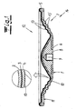
Der Elastomerkörper kann tellerförmig, insbesondere als kreisförmiger Teller ausgebildet sein, der eine Tellerwand mit einer Einspannfläche, einen Boden und einen den Tellerrand mit dem Boden verbindenden biegsamen Membranabschnitt aufweist. Der Boden des Elastomerkörpers kann einen einvulkanisierten Kern mit einer Anschlusseinrichtung für eine Kolbenstange oder alternativ eine mittige Öffnung zum Anschluss an eine Kolbenstange aufweisen. Der Elastomerkörper enthält vorzugsweise eine textile Verstärkungseinlage, kann jedoch auch ohne eine derartige Verstärkung ausgebildet sein. Ferner kann der Elastomerkörper auf seiner elastomeren Rückseite im Übergangsbereich zwischen dem Tellerrand und dem biegsamen Membranabschnitt eine ringförmig umlaufende Vertiefung enthalten.The elastomeric body may be plate-shaped, in particular designed as a circular plate, which has a plate wall with a clamping surface, a bottom and a plate rim connecting to the bottom flexible membrane portion. The bottom of the elastomeric body may have a vulcanized core with a connecting device for a piston rod or alternatively a central opening for connection to a piston rod. The elastomeric body preferably contains a textile reinforcing insert, but may also be formed without such reinforcement. Furthermore, the elastomeric body may contain on its elastomeric back in the transition region between the plate edge and the flexible membrane portion an annular circumferential recess.
Im Folgenden wird die Erfindung anhand einer lediglich ein Ausführungsbeispiel darstellenden Zeichnung ausführlich erläutert. Es zeigen schematisch:
- Fig. 1
- einen radialen Querschnitt durch eine erfindungsgemäße Verbundmembran,
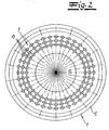
- Fig. 2
- eine Draufsicht auf die in
Fig. 1 dargestellte Verbundmembran, - Fig. 3
- eine Unteransicht der in
Fig. 1 dargestellten Verbundmembran, - Fig. 4
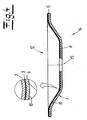
- eine alternative Ausführungsform der Erfindung in einer der
Fig. 1 entsprechenden Darstellung. - Fig. 5
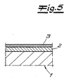
- eine ausschnittsweise Darstellung einer weiteren Ausführungsform der Erfindung.
- Fig. 1
- a radial cross section through a composite membrane according to the invention,
- Fig. 2
- a top view of the in
Fig. 1 illustrated composite membrane, - Fig. 3
- a bottom view of in
Fig. 1 represented composite membrane, - Fig. 4
- an alternative embodiment of the invention in one of
Fig. 1 corresponding representation. - Fig. 5
- a partial view of another embodiment of the invention.
In
Der
Die
Gemäß einer weiteren, in
Claims (8)
- A composite diaphragm having an elastomer body (1) and an application layer (2) of polytetrafluoroethylene (PTFE) applied to the elastomer body (1), whereby a barrier layer (3), also designed as a permeation barrier, is additionally provided, arranged between the application layer (2) and the elastomer body (1) or applied to the side of the application layer (2) facing away from the elastomer body (1), characterized in that at least one intermediate layer (4) containing PTFE is arranged between the barrier layer (3) and the elastomer body (1).
- The composite diaphragm according to claim 1, characterized in that the intermediate layer (4) is made of PTFE.
- The composite diaphragm according to claim 1 or 2, characterized in that the barrier layer (3) is a perfluoroalkoxy copolymer (PFA).
- The composite diaphragm according to claim 3, characterized in that the barrier layer (3) comprises PFA.
- The composite diaphragm according to any one of claims 1 to 4, characterized in that the elastomer body (1) is designed in the form of a plate.
- The composite diaphragm according to claim 5, characterized in that the elastomer body (1) is designed as a circular plate having a plate edge (5) with a clamping surface, a bottom (6) and a flexible diaphragm section (7) connecting the plate edge (5) to the bottom (6).
- The composite diaphragm according to claim 6, characterized in that the bottom (6) of the elastomer body (1) comprises a core (8) which is vulcanized in place and has a connecting mechanism (9) for a piston rod or the bottom has a central opening (15) for connection to a piston rod.
- The composite diaphragm according to any one of claims 1 to 7, characterized in that the elastomer body (1) contains a textile reinforcing insert (10).
Priority Applications (5)
| Application Number | Priority Date | Filing Date | Title |
|---|---|---|---|
| AT06015242T ATE446449T1 (en) | 2006-07-21 | 2006-07-21 | COMPOSITE MEMBRANE |
| DE200650005200 DE502006005200D1 (en) | 2006-07-21 | 2006-07-21 | composite membrane |
| EP20060015242 EP1892414B1 (en) | 2006-07-21 | 2006-07-21 | Composite membrane |
| PL06015242T PL1892414T3 (en) | 2006-07-21 | 2006-07-21 | Composite membrane |
| US11/580,098 US7905172B2 (en) | 2006-07-21 | 2006-10-12 | Laminate membrane |
Applications Claiming Priority (1)
| Application Number | Priority Date | Filing Date | Title |
|---|---|---|---|
| EP20060015242 EP1892414B1 (en) | 2006-07-21 | 2006-07-21 | Composite membrane |
Publications (2)
| Publication Number | Publication Date |
|---|---|
| EP1892414A1 EP1892414A1 (en) | 2008-02-27 |
| EP1892414B1 true EP1892414B1 (en) | 2009-10-21 |
Family
ID=37309241
Family Applications (1)
| Application Number | Title | Priority Date | Filing Date |
|---|---|---|---|
| EP20060015242 Active EP1892414B1 (en) | 2006-07-21 | 2006-07-21 | Composite membrane |
Country Status (5)
| Country | Link |
|---|---|
| US (1) | US7905172B2 (en) |
| EP (1) | EP1892414B1 (en) |
| AT (1) | ATE446449T1 (en) |
| DE (1) | DE502006005200D1 (en) |
| PL (1) | PL1892414T3 (en) |
Families Citing this family (27)
| Publication number | Priority date | Publication date | Assignee | Title |
|---|---|---|---|---|
| US20090045122A1 (en) * | 2007-08-17 | 2009-02-19 | Jun-Nan Lin | Fine bubble diffuser membrane for water and wastewater treatment |
| CN101868203B (en) | 2007-11-21 | 2014-10-22 | 史密夫及内修公开有限公司 | Wound dressing |
| WO2010000037A1 (en) * | 2008-07-03 | 2010-01-07 | Infrastructure Technology Limited | Membrane |
| GB201015656D0 (en) | 2010-09-20 | 2010-10-27 | Smith & Nephew | Pressure control apparatus |
| US9675946B2 (en) * | 2010-12-29 | 2017-06-13 | Whirlpool Corporation | Mixing bowl liner and lid |
| US9084845B2 (en) | 2011-11-02 | 2015-07-21 | Smith & Nephew Plc | Reduced pressure therapy apparatuses and methods of using same |
| JP5889649B2 (en) | 2012-01-26 | 2016-03-22 | サーパス工業株式会社 | Flow control device |
| JP5889648B2 (en) * | 2012-01-26 | 2016-03-22 | サーパス工業株式会社 | Flow control device |
| WO2013140255A1 (en) | 2012-03-20 | 2013-09-26 | Smith & Nephew Plc | Controlling operation of a reduced pressure therapy system based on dynamic duty cycle threshold determination |
| US9427505B2 (en) | 2012-05-15 | 2016-08-30 | Smith & Nephew Plc | Negative pressure wound therapy apparatus |
| JP6271871B2 (en) * | 2013-06-04 | 2018-01-31 | 株式会社フジキン | Diaphragm valve |
| DE102013214304A1 (en) * | 2013-07-22 | 2015-01-22 | Gemü Gebr. Müller Apparatebau Gmbh & Co. Kommanditgesellschaft | Membrane and process for its production |
| DE102014000358A1 (en) * | 2014-01-09 | 2015-07-09 | Hydac Technology Gmbh | accumulator |
| CH709942A2 (en) | 2014-07-21 | 2016-01-29 | Dätwyler Sealing Solutions Internat Ag | Control diaphragm for diaphragm carburetors. |
| DE102014014740A1 (en) * | 2014-10-09 | 2016-04-14 | A.RAYMOND et Cie. SCS | Shut-off body for a valve and valve with such a shut-off body |
| US10780202B2 (en) | 2014-12-22 | 2020-09-22 | Smith & Nephew Plc | Noise reduction for negative pressure wound therapy apparatuses |
| DE102015226463A1 (en) * | 2015-12-22 | 2017-06-22 | Robert Bosch Gmbh | Magnetic actuator for a delivery unit |
| CH712028A1 (en) * | 2016-01-11 | 2017-07-14 | Dätwyler Schweiz Ag | Regulating diaphragm for diaphragm carburettor. |
| US20190162177A1 (en) * | 2016-08-01 | 2019-05-30 | Walbro Llc | Fluid driven diaphragm pump |
| US10920763B2 (en) * | 2016-09-01 | 2021-02-16 | Wanner Engineering, Inc. | Diaphragm with edge seal |
| CH712963A1 (en) | 2016-09-29 | 2018-03-29 | Daetwyler Schweiz Ag | Pump diaphragm for a diaphragm pump for conveying a fluid. |
| CN108521784B (en) * | 2017-09-28 | 2021-10-08 | 深圳市大疆创新科技有限公司 | Pump device and plant protection unmanned aerial vehicle with same |
| KR102493794B1 (en) * | 2017-10-17 | 2023-01-31 | 니폰 필라고교 가부시키가이샤 | resin member |
| CN108372669A (en) * | 2018-03-06 | 2018-08-07 | 南京道隆生物科技有限公司 | A kind of sanitation-grade diaphragm and its manufacturing process |
| AU2019255317B2 (en) | 2018-04-18 | 2023-08-10 | Wanner Engineering, Inc. | Device for protecting a diaphragm pump from pressure differential |
| CN112135971A (en) * | 2019-07-29 | 2020-12-25 | 深圳市大疆创新科技有限公司 | Diaphragm pump |
| US11754181B2 (en) * | 2022-01-28 | 2023-09-12 | Graco Minnesota Inc. | Overmolded diaphragm for use in a pump |
Family Cites Families (8)
| Publication number | Priority date | Publication date | Assignee | Title |
|---|---|---|---|---|
| US4781535A (en) * | 1987-11-13 | 1988-11-01 | Pulsafeeder, Inc. | Apparatus and method for sensing diaphragm failures in reciprocating pumps |
| US5217797A (en) * | 1992-02-19 | 1993-06-08 | W. L. Gore & Associates, Inc. | Chemically resistant diaphragm |
| FR2766524B1 (en) * | 1997-07-28 | 1999-10-22 | Clextral | ELASTIC MEMBRANE FOR A MEMBRANE PUMP |
| WO2003024713A1 (en) * | 2001-09-18 | 2003-03-27 | Mykrolis Corporation | High-strength, chemically resistant laminar film with limited extractables |
| DE10227192B4 (en) * | 2002-06-18 | 2009-08-06 | Ulman Dichtungstechnik Gmbh | Composite membrane for diaphragm pumps |
| DE10227193B4 (en) * | 2002-06-18 | 2007-05-10 | Ulman Dichtungstechnik Gmbh | Composite membrane for diaphragm pumps |
| EP1406034A1 (en) * | 2002-10-05 | 2004-04-07 | Plastigum AG, Gummi- und Kunststoff-Fabrik | Membrane arrangement for membrane valves or membrane pumps |
| EP1518656B1 (en) * | 2003-09-26 | 2006-08-23 | Edo Giardini | Process for making a membrane for fluid-control apparatuses, and membrane made thereby |
-
2006
- 2006-07-21 AT AT06015242T patent/ATE446449T1/en active
- 2006-07-21 PL PL06015242T patent/PL1892414T3/en unknown
- 2006-07-21 DE DE200650005200 patent/DE502006005200D1/en active Active
- 2006-07-21 EP EP20060015242 patent/EP1892414B1/en active Active
- 2006-10-12 US US11/580,098 patent/US7905172B2/en active Active
Also Published As
| Publication number | Publication date |
|---|---|
| EP1892414A1 (en) | 2008-02-27 |
| ATE446449T1 (en) | 2009-11-15 |
| PL1892414T3 (en) | 2010-05-31 |
| US7905172B2 (en) | 2011-03-15 |
| DE502006005200D1 (en) | 2009-12-03 |
| US20080020178A1 (en) | 2008-01-24 |
Similar Documents
| Publication | Publication Date | Title |
|---|---|---|
| EP1892414B1 (en) | Composite membrane | |
| DE10227193B4 (en) | Composite membrane for diaphragm pumps | |
| EP0765449B1 (en) | Non-return valve | |
| WO2009021605A1 (en) | Nonreturn valve, in particular for medical uses | |
| DE102012012971A1 (en) | Damping element for a motor vehicle hydraulic system | |
| EP0910745B1 (en) | Diaphragm for a diaphragm pump | |
| DE102016003767A1 (en) | Switching diaphragm for a pressure control valve | |
| DE102010022410A1 (en) | Check valve, in particular for medical applications | |
| DE102016013008A1 (en) | Unit for regulating or controlling a fluid pressure | |
| DE202015009718U1 (en) | Shut-off body for a valve and valve with such a shut-off body | |
| EP3978751B1 (en) | Composite membrane for membrane pumps | |
| DE2628314A1 (en) | NON-RETURN VALVE, IN PARTICULAR FOR VACUUM PRESSURE DEVICES IN MOTOR VEHICLES | |
| WO2015022144A1 (en) | Sealing ring | |
| EP1525399A1 (en) | Diaphragm pump | |
| DE10227192B4 (en) | Composite membrane for diaphragm pumps | |
| DE102006055556B4 (en) | diaphragm pump | |
| DE1400589A1 (en) | Diaphragm valve | |
| WO2004007960A1 (en) | Multilayer membrane | |
| EP4119819A1 (en) | Membrane assembly with reinforcing elements | |
| DE102013215266A1 (en) | valve means | |
| DE212011100100U1 (en) | Piston head with sealing arrangement | |
| DE102018124467A1 (en) | Hydraulic micro valve | |
| DE2821136A1 (en) | DOUBLE MEMBRANE BODY | |
| DE102017010136A1 (en) | Valve and pneumatic brake system | |
| DE3813500A1 (en) | Diaphragm pump or diaphragm compressor |
Legal Events
| Date | Code | Title | Description |
|---|---|---|---|
| PUAI | Public reference made under article 153(3) epc to a published international application that has entered the european phase |
Free format text: ORIGINAL CODE: 0009012 |
|
| 17P | Request for examination filed |
Effective date: 20061223 |
|
| AK | Designated contracting states |
Kind code of ref document: A1 Designated state(s): AT BE BG CH CY CZ DE DK EE ES FI FR GB GR HU IE IS IT LI LT LU LV MC NL PL PT RO SE SI SK TR |
|
| AX | Request for extension of the european patent |
Extension state: AL BA HR MK YU |
|
| 17Q | First examination report despatched |
Effective date: 20080207 |
|
| AKX | Designation fees paid |
Designated state(s): AT BE BG CH CY CZ DE DK EE ES FI FR GB GR HU IE IS IT LI LT LU LV MC NL PL PT RO SE SI SK TR |
|
| GRAP | Despatch of communication of intention to grant a patent |
Free format text: ORIGINAL CODE: EPIDOSNIGR1 |
|
| GRAJ | Information related to disapproval of communication of intention to grant by the applicant or resumption of examination proceedings by the epo deleted |
Free format text: ORIGINAL CODE: EPIDOSDIGR1 |
|
| GRAP | Despatch of communication of intention to grant a patent |
Free format text: ORIGINAL CODE: EPIDOSNIGR1 |
|
| GRAS | Grant fee paid |
Free format text: ORIGINAL CODE: EPIDOSNIGR3 |
|
| GRAA | (expected) grant |
Free format text: ORIGINAL CODE: 0009210 |
|
| AK | Designated contracting states |
Kind code of ref document: B1 Designated state(s): AT BE BG CH CY CZ DE DK EE ES FI FR GB GR HU IE IS IT LI LT LU LV MC NL PL PT RO SE SI SK TR |
|
| REG | Reference to a national code |
Ref country code: GB Ref legal event code: FG4D Free format text: NOT ENGLISH |
|
| REG | Reference to a national code |
Ref country code: CH Ref legal event code: EP |
|
| REG | Reference to a national code |
Ref country code: IE Ref legal event code: FG4D |
|
| REF | Corresponds to: |
Ref document number: 502006005200 Country of ref document: DE Date of ref document: 20091203 Kind code of ref document: P |
|
| LTIE | Lt: invalidation of european patent or patent extension |
Effective date: 20091021 |
|
| PG25 | Lapsed in a contracting state [announced via postgrant information from national office to epo] |
Ref country code: SE Free format text: LAPSE BECAUSE OF FAILURE TO SUBMIT A TRANSLATION OF THE DESCRIPTION OR TO PAY THE FEE WITHIN THE PRESCRIBED TIME-LIMIT Effective date: 20091021 Ref country code: PT Free format text: LAPSE BECAUSE OF FAILURE TO SUBMIT A TRANSLATION OF THE DESCRIPTION OR TO PAY THE FEE WITHIN THE PRESCRIBED TIME-LIMIT Effective date: 20100222 Ref country code: LT Free format text: LAPSE BECAUSE OF FAILURE TO SUBMIT A TRANSLATION OF THE DESCRIPTION OR TO PAY THE FEE WITHIN THE PRESCRIBED TIME-LIMIT Effective date: 20091021 Ref country code: IS Free format text: LAPSE BECAUSE OF FAILURE TO SUBMIT A TRANSLATION OF THE DESCRIPTION OR TO PAY THE FEE WITHIN THE PRESCRIBED TIME-LIMIT Effective date: 20100221 Ref country code: FI Free format text: LAPSE BECAUSE OF FAILURE TO SUBMIT A TRANSLATION OF THE DESCRIPTION OR TO PAY THE FEE WITHIN THE PRESCRIBED TIME-LIMIT Effective date: 20091021 Ref country code: ES Free format text: LAPSE BECAUSE OF FAILURE TO SUBMIT A TRANSLATION OF THE DESCRIPTION OR TO PAY THE FEE WITHIN THE PRESCRIBED TIME-LIMIT Effective date: 20100201 |
|
| REG | Reference to a national code |
Ref country code: IE Ref legal event code: FD4D |
|
| PG25 | Lapsed in a contracting state [announced via postgrant information from national office to epo] |
Ref country code: SI Free format text: LAPSE BECAUSE OF FAILURE TO SUBMIT A TRANSLATION OF THE DESCRIPTION OR TO PAY THE FEE WITHIN THE PRESCRIBED TIME-LIMIT Effective date: 20091021 Ref country code: LV Free format text: LAPSE BECAUSE OF FAILURE TO SUBMIT A TRANSLATION OF THE DESCRIPTION OR TO PAY THE FEE WITHIN THE PRESCRIBED TIME-LIMIT Effective date: 20091021 |
|
| REG | Reference to a national code |
Ref country code: PL Ref legal event code: T3 |
|
| PG25 | Lapsed in a contracting state [announced via postgrant information from national office to epo] |
Ref country code: RO Free format text: LAPSE BECAUSE OF FAILURE TO SUBMIT A TRANSLATION OF THE DESCRIPTION OR TO PAY THE FEE WITHIN THE PRESCRIBED TIME-LIMIT Effective date: 20091021 Ref country code: IE Free format text: LAPSE BECAUSE OF FAILURE TO SUBMIT A TRANSLATION OF THE DESCRIPTION OR TO PAY THE FEE WITHIN THE PRESCRIBED TIME-LIMIT Effective date: 20091021 Ref country code: EE Free format text: LAPSE BECAUSE OF FAILURE TO SUBMIT A TRANSLATION OF THE DESCRIPTION OR TO PAY THE FEE WITHIN THE PRESCRIBED TIME-LIMIT Effective date: 20091021 Ref country code: DK Free format text: LAPSE BECAUSE OF FAILURE TO SUBMIT A TRANSLATION OF THE DESCRIPTION OR TO PAY THE FEE WITHIN THE PRESCRIBED TIME-LIMIT Effective date: 20091021 Ref country code: BG Free format text: LAPSE BECAUSE OF FAILURE TO SUBMIT A TRANSLATION OF THE DESCRIPTION OR TO PAY THE FEE WITHIN THE PRESCRIBED TIME-LIMIT Effective date: 20100121 |
|
| PLBE | No opposition filed within time limit |
Free format text: ORIGINAL CODE: 0009261 |
|
| STAA | Information on the status of an ep patent application or granted ep patent |
Free format text: STATUS: NO OPPOSITION FILED WITHIN TIME LIMIT |
|
| PG25 | Lapsed in a contracting state [announced via postgrant information from national office to epo] |
Ref country code: SK Free format text: LAPSE BECAUSE OF FAILURE TO SUBMIT A TRANSLATION OF THE DESCRIPTION OR TO PAY THE FEE WITHIN THE PRESCRIBED TIME-LIMIT Effective date: 20091021 Ref country code: CZ Free format text: LAPSE BECAUSE OF FAILURE TO SUBMIT A TRANSLATION OF THE DESCRIPTION OR TO PAY THE FEE WITHIN THE PRESCRIBED TIME-LIMIT Effective date: 20091021 |
|
| 26N | No opposition filed |
Effective date: 20100722 |
|
| PG25 | Lapsed in a contracting state [announced via postgrant information from national office to epo] |
Ref country code: GR Free format text: LAPSE BECAUSE OF FAILURE TO SUBMIT A TRANSLATION OF THE DESCRIPTION OR TO PAY THE FEE WITHIN THE PRESCRIBED TIME-LIMIT Effective date: 20100122 |
|
| BERE | Be: lapsed |
Owner name: ULMAN DICHTUNGSTECHNIK G.M.B.H. Effective date: 20100731 |
|
| PG25 | Lapsed in a contracting state [announced via postgrant information from national office to epo] |
Ref country code: MC Free format text: LAPSE BECAUSE OF NON-PAYMENT OF DUE FEES Effective date: 20100731 |
|
| REG | Reference to a national code |
Ref country code: CH Ref legal event code: PL |
|
| REG | Reference to a national code |
Ref country code: FR Ref legal event code: ST Effective date: 20110331 |
|
| PG25 | Lapsed in a contracting state [announced via postgrant information from national office to epo] |
Ref country code: CH Free format text: LAPSE BECAUSE OF NON-PAYMENT OF DUE FEES Effective date: 20100731 Ref country code: LI Free format text: LAPSE BECAUSE OF NON-PAYMENT OF DUE FEES Effective date: 20100731 |
|
| PG25 | Lapsed in a contracting state [announced via postgrant information from national office to epo] |
Ref country code: FR Free format text: LAPSE BECAUSE OF NON-PAYMENT OF DUE FEES Effective date: 20100802 |
|
| PG25 | Lapsed in a contracting state [announced via postgrant information from national office to epo] |
Ref country code: BE Free format text: LAPSE BECAUSE OF NON-PAYMENT OF DUE FEES Effective date: 20100731 |
|
| PG25 | Lapsed in a contracting state [announced via postgrant information from national office to epo] |
Ref country code: CY Free format text: LAPSE BECAUSE OF FAILURE TO SUBMIT A TRANSLATION OF THE DESCRIPTION OR TO PAY THE FEE WITHIN THE PRESCRIBED TIME-LIMIT Effective date: 20091021 |
|
| PG25 | Lapsed in a contracting state [announced via postgrant information from national office to epo] |
Ref country code: HU Free format text: LAPSE BECAUSE OF FAILURE TO SUBMIT A TRANSLATION OF THE DESCRIPTION OR TO PAY THE FEE WITHIN THE PRESCRIBED TIME-LIMIT Effective date: 20100422 Ref country code: LU Free format text: LAPSE BECAUSE OF NON-PAYMENT OF DUE FEES Effective date: 20100721 |
|
| PG25 | Lapsed in a contracting state [announced via postgrant information from national office to epo] |
Ref country code: TR Free format text: LAPSE BECAUSE OF FAILURE TO SUBMIT A TRANSLATION OF THE DESCRIPTION OR TO PAY THE FEE WITHIN THE PRESCRIBED TIME-LIMIT Effective date: 20091021 |
|
| REG | Reference to a national code |
Ref country code: AT Ref legal event code: MM01 Ref document number: 446449 Country of ref document: AT Kind code of ref document: T Effective date: 20110721 |
|
| PG25 | Lapsed in a contracting state [announced via postgrant information from national office to epo] |
Ref country code: AT Free format text: LAPSE BECAUSE OF NON-PAYMENT OF DUE FEES Effective date: 20110721 |
|
| PGFP | Annual fee paid to national office [announced via postgrant information from national office to epo] |
Ref country code: GB Payment date: 20190719 Year of fee payment: 14 |
|
| GBPC | Gb: european patent ceased through non-payment of renewal fee |
Effective date: 20200721 |
|
| PG25 | Lapsed in a contracting state [announced via postgrant information from national office to epo] |
Ref country code: GB Free format text: LAPSE BECAUSE OF NON-PAYMENT OF DUE FEES Effective date: 20200721 |
|
| P01 | Opt-out of the competence of the unified patent court (upc) registered |
Effective date: 20230530 |
|
| PGFP | Annual fee paid to national office [announced via postgrant information from national office to epo] |
Ref country code: NL Payment date: 20230719 Year of fee payment: 18 |
|
| PGFP | Annual fee paid to national office [announced via postgrant information from national office to epo] |
Ref country code: IT Payment date: 20230724 Year of fee payment: 18 |
|
| PGFP | Annual fee paid to national office [announced via postgrant information from national office to epo] |
Ref country code: PL Payment date: 20230714 Year of fee payment: 18 Ref country code: DE Payment date: 20230616 Year of fee payment: 18 |