EP1518656B1 - Process for making a membrane for fluid-control apparatuses, and membrane made thereby - Google Patents
Process for making a membrane for fluid-control apparatuses, and membrane made thereby Download PDFInfo
- Publication number
- EP1518656B1 EP1518656B1 EP20030425624 EP03425624A EP1518656B1 EP 1518656 B1 EP1518656 B1 EP 1518656B1 EP 20030425624 EP20030425624 EP 20030425624 EP 03425624 A EP03425624 A EP 03425624A EP 1518656 B1 EP1518656 B1 EP 1518656B1
- Authority
- EP
- European Patent Office
- Prior art keywords
- layer
- plastic material
- membrane
- injection
- moulding
- Prior art date
- Legal status (The legal status is an assumption and is not a legal conclusion. Google has not performed a legal analysis and makes no representation as to the accuracy of the status listed.)
- Expired - Lifetime
Links
- 239000012528 membrane Substances 0.000 title claims abstract description 72
- 238000000034 method Methods 0.000 title claims abstract description 35
- 239000000463 material Substances 0.000 claims abstract description 84
- 229920003023 plastic Polymers 0.000 claims abstract description 72
- 239000004033 plastic Substances 0.000 claims abstract description 72
- 238000000465 moulding Methods 0.000 claims abstract description 35
- 229920002725 thermoplastic elastomer Polymers 0.000 claims abstract description 28
- 239000012530 fluid Substances 0.000 claims abstract description 20
- 238000001746 injection moulding Methods 0.000 claims abstract description 12
- 229920000098 polyolefin Polymers 0.000 claims abstract description 8
- 239000004952 Polyamide Substances 0.000 claims abstract description 7
- 229920002647 polyamide Polymers 0.000 claims abstract description 7
- 229920000728 polyester Polymers 0.000 claims abstract description 6
- 239000011347 resin Substances 0.000 claims abstract description 6
- 229920005989 resin Polymers 0.000 claims abstract description 6
- 125000000391 vinyl group Chemical group [H]C([*])=C([H])[H] 0.000 claims abstract description 5
- 229920002554 vinyl polymer Polymers 0.000 claims abstract description 5
- 229920001903 high density polyethylene Polymers 0.000 claims description 21
- 239000004700 high-density polyethylene Substances 0.000 claims description 21
- 238000002347 injection Methods 0.000 claims description 17
- 239000007924 injection Substances 0.000 claims description 17
- 239000004699 Ultra-high molecular weight polyethylene Substances 0.000 claims description 14
- -1 polyethylene Polymers 0.000 claims description 13
- 229920000785 ultra high molecular weight polyethylene Polymers 0.000 claims description 13
- 239000004698 Polyethylene Substances 0.000 claims description 9
- 229920001971 elastomer Polymers 0.000 claims description 9
- 229920000573 polyethylene Polymers 0.000 claims description 9
- 239000000806 elastomer Substances 0.000 claims description 8
- 238000002844 melting Methods 0.000 claims description 3
- 230000008018 melting Effects 0.000 claims description 3
- 230000008878 coupling Effects 0.000 abstract 1
- 238000010168 coupling process Methods 0.000 abstract 1
- 238000005859 coupling reaction Methods 0.000 abstract 1
- 239000010410 layer Substances 0.000 description 82
- 229920001343 polytetrafluoroethylene Polymers 0.000 description 13
- 239000004810 polytetrafluoroethylene Substances 0.000 description 13
- 239000000126 substance Substances 0.000 description 8
- 239000000853 adhesive Substances 0.000 description 7
- 238000004026 adhesive bonding Methods 0.000 description 7
- 230000001070 adhesive effect Effects 0.000 description 7
- 239000013043 chemical agent Substances 0.000 description 6
- 239000007767 bonding agent Substances 0.000 description 5
- 229920003031 santoprene Polymers 0.000 description 5
- 229920006362 Teflon® Polymers 0.000 description 4
- 238000004519 manufacturing process Methods 0.000 description 4
- 229920006347 Elastollan Polymers 0.000 description 2
- 229920002449 FKM Polymers 0.000 description 2
- 229920002614 Polyether block amide Polymers 0.000 description 2
- 238000006073 displacement reaction Methods 0.000 description 2
- 239000007788 liquid Substances 0.000 description 2
- 229920001084 poly(chloroprene) Polymers 0.000 description 2
- 239000000843 powder Substances 0.000 description 2
- 239000002904 solvent Substances 0.000 description 2
- LFQSCWFLJHTTHZ-UHFFFAOYSA-N Ethanol Chemical compound CCO LFQSCWFLJHTTHZ-UHFFFAOYSA-N 0.000 description 1
- FAPWRFPIFSIZLT-UHFFFAOYSA-M Sodium chloride Chemical compound [Na+].[Cl-] FAPWRFPIFSIZLT-UHFFFAOYSA-M 0.000 description 1
- 238000005299 abrasion Methods 0.000 description 1
- 239000002253 acid Substances 0.000 description 1
- 150000007513 acids Chemical class 0.000 description 1
- 239000000654 additive Substances 0.000 description 1
- 239000012670 alkaline solution Substances 0.000 description 1
- 125000003118 aryl group Chemical group 0.000 description 1
- 230000015572 biosynthetic process Effects 0.000 description 1
- 238000005266 casting Methods 0.000 description 1
- 239000003518 caustics Substances 0.000 description 1
- 230000006835 compression Effects 0.000 description 1
- 238000007906 compression Methods 0.000 description 1
- 238000000748 compression moulding Methods 0.000 description 1
- 238000001816 cooling Methods 0.000 description 1
- 238000005260 corrosion Methods 0.000 description 1
- 230000007797 corrosion Effects 0.000 description 1
- 230000001419 dependent effect Effects 0.000 description 1
- 150000002148 esters Chemical class 0.000 description 1
- 238000004299 exfoliation Methods 0.000 description 1
- 238000001125 extrusion Methods 0.000 description 1
- 238000010438 heat treatment Methods 0.000 description 1
- 238000003780 insertion Methods 0.000 description 1
- 230000037431 insertion Effects 0.000 description 1
- 238000005304 joining Methods 0.000 description 1
- 239000002184 metal Substances 0.000 description 1
- 229920003052 natural elastomer Polymers 0.000 description 1
- 229920001194 natural rubber Polymers 0.000 description 1
- 229920001296 polysiloxane Polymers 0.000 description 1
- 229920003225 polyurethane elastomer Polymers 0.000 description 1
- 238000002360 preparation method Methods 0.000 description 1
- 239000000376 reactant Substances 0.000 description 1
- 239000005060 rubber Substances 0.000 description 1
- 239000002356 single layer Substances 0.000 description 1
- 238000005245 sintering Methods 0.000 description 1
- 239000011780 sodium chloride Substances 0.000 description 1
- 239000000243 solution Substances 0.000 description 1
- 238000010186 staining Methods 0.000 description 1
- 229920003051 synthetic elastomer Polymers 0.000 description 1
- 239000005061 synthetic rubber Substances 0.000 description 1
- 238000003856 thermoforming Methods 0.000 description 1
- 239000012815 thermoplastic material Substances 0.000 description 1
- XLYOFNOQVPJJNP-UHFFFAOYSA-N water Substances O XLYOFNOQVPJJNP-UHFFFAOYSA-N 0.000 description 1
- 238000003466 welding Methods 0.000 description 1
Images
Classifications
-
- B—PERFORMING OPERATIONS; TRANSPORTING
- B29—WORKING OF PLASTICS; WORKING OF SUBSTANCES IN A PLASTIC STATE IN GENERAL
- B29C—SHAPING OR JOINING OF PLASTICS; SHAPING OF MATERIAL IN A PLASTIC STATE, NOT OTHERWISE PROVIDED FOR; AFTER-TREATMENT OF THE SHAPED PRODUCTS, e.g. REPAIRING
- B29C45/00—Injection moulding, i.e. forcing the required volume of moulding material through a nozzle into a closed mould; Apparatus therefor
- B29C45/14—Injection moulding, i.e. forcing the required volume of moulding material through a nozzle into a closed mould; Apparatus therefor incorporating preformed parts or layers, e.g. injection moulding around inserts or for coating articles
- B29C45/14336—Coating a portion of the article, e.g. the edge of the article
-
- B—PERFORMING OPERATIONS; TRANSPORTING
- B29—WORKING OF PLASTICS; WORKING OF SUBSTANCES IN A PLASTIC STATE IN GENERAL
- B29C—SHAPING OR JOINING OF PLASTICS; SHAPING OF MATERIAL IN A PLASTIC STATE, NOT OTHERWISE PROVIDED FOR; AFTER-TREATMENT OF THE SHAPED PRODUCTS, e.g. REPAIRING
- B29C45/00—Injection moulding, i.e. forcing the required volume of moulding material through a nozzle into a closed mould; Apparatus therefor
- B29C45/16—Making multilayered or multicoloured articles
- B29C45/1676—Making multilayered or multicoloured articles using a soft material and a rigid material, e.g. making articles with a sealing part
-
- F—MECHANICAL ENGINEERING; LIGHTING; HEATING; WEAPONS; BLASTING
- F04—POSITIVE - DISPLACEMENT MACHINES FOR LIQUIDS; PUMPS FOR LIQUIDS OR ELASTIC FLUIDS
- F04B—POSITIVE-DISPLACEMENT MACHINES FOR LIQUIDS; PUMPS
- F04B43/00—Machines, pumps, or pumping installations having flexible working members
- F04B43/0009—Special features
- F04B43/0054—Special features particularities of the flexible members
-
- F—MECHANICAL ENGINEERING; LIGHTING; HEATING; WEAPONS; BLASTING
- F16—ENGINEERING ELEMENTS AND UNITS; GENERAL MEASURES FOR PRODUCING AND MAINTAINING EFFECTIVE FUNCTIONING OF MACHINES OR INSTALLATIONS; THERMAL INSULATION IN GENERAL
- F16J—PISTONS; CYLINDERS; SEALINGS
- F16J3/00—Diaphragms; Bellows; Bellows pistons
- F16J3/02—Diaphragms
-
- F—MECHANICAL ENGINEERING; LIGHTING; HEATING; WEAPONS; BLASTING
- F16—ENGINEERING ELEMENTS AND UNITS; GENERAL MEASURES FOR PRODUCING AND MAINTAINING EFFECTIVE FUNCTIONING OF MACHINES OR INSTALLATIONS; THERMAL INSULATION IN GENERAL
- F16J—PISTONS; CYLINDERS; SEALINGS
- F16J9/00—Piston-rings, e.g. non-metallic piston-rings, seats therefor; Ring sealings of similar construction
- F16J9/26—Piston-rings, e.g. non-metallic piston-rings, seats therefor; Ring sealings of similar construction characterised by the use of particular materials
-
- B—PERFORMING OPERATIONS; TRANSPORTING
- B29—WORKING OF PLASTICS; WORKING OF SUBSTANCES IN A PLASTIC STATE IN GENERAL
- B29C—SHAPING OR JOINING OF PLASTICS; SHAPING OF MATERIAL IN A PLASTIC STATE, NOT OTHERWISE PROVIDED FOR; AFTER-TREATMENT OF THE SHAPED PRODUCTS, e.g. REPAIRING
- B29C45/00—Injection moulding, i.e. forcing the required volume of moulding material through a nozzle into a closed mould; Apparatus therefor
- B29C45/14—Injection moulding, i.e. forcing the required volume of moulding material through a nozzle into a closed mould; Apparatus therefor incorporating preformed parts or layers, e.g. injection moulding around inserts or for coating articles
- B29C45/1418—Injection moulding, i.e. forcing the required volume of moulding material through a nozzle into a closed mould; Apparatus therefor incorporating preformed parts or layers, e.g. injection moulding around inserts or for coating articles the inserts being deformed or preformed, e.g. by the injection pressure
-
- B—PERFORMING OPERATIONS; TRANSPORTING
- B29—WORKING OF PLASTICS; WORKING OF SUBSTANCES IN A PLASTIC STATE IN GENERAL
- B29K—INDEXING SCHEME ASSOCIATED WITH SUBCLASSES B29B, B29C OR B29D, RELATING TO MOULDING MATERIALS OR TO MATERIALS FOR MOULDS, REINFORCEMENTS, FILLERS OR PREFORMED PARTS, e.g. INSERTS
- B29K2023/00—Use of polyalkenes or derivatives thereof as moulding material
- B29K2023/04—Polymers of ethylene
- B29K2023/06—PE, i.e. polyethylene
- B29K2023/0658—PE, i.e. polyethylene characterised by its molecular weight
- B29K2023/0683—UHMWPE, i.e. ultra high molecular weight polyethylene
-
- B—PERFORMING OPERATIONS; TRANSPORTING
- B29—WORKING OF PLASTICS; WORKING OF SUBSTANCES IN A PLASTIC STATE IN GENERAL
- B29K—INDEXING SCHEME ASSOCIATED WITH SUBCLASSES B29B, B29C OR B29D, RELATING TO MOULDING MATERIALS OR TO MATERIALS FOR MOULDS, REINFORCEMENTS, FILLERS OR PREFORMED PARTS, e.g. INSERTS
- B29K2221/00—Use of unspecified rubbers as reinforcement
- B29K2221/003—Thermoplastic elastomers
-
- B—PERFORMING OPERATIONS; TRANSPORTING
- B29—WORKING OF PLASTICS; WORKING OF SUBSTANCES IN A PLASTIC STATE IN GENERAL
- B29L—INDEXING SCHEME ASSOCIATED WITH SUBCLASS B29C, RELATING TO PARTICULAR ARTICLES
- B29L2031/00—Other particular articles
- B29L2031/755—Membranes, diaphragms
-
- Y—GENERAL TAGGING OF NEW TECHNOLOGICAL DEVELOPMENTS; GENERAL TAGGING OF CROSS-SECTIONAL TECHNOLOGIES SPANNING OVER SEVERAL SECTIONS OF THE IPC; TECHNICAL SUBJECTS COVERED BY FORMER USPC CROSS-REFERENCE ART COLLECTIONS [XRACs] AND DIGESTS
- Y10—TECHNICAL SUBJECTS COVERED BY FORMER USPC
- Y10T—TECHNICAL SUBJECTS COVERED BY FORMER US CLASSIFICATION
- Y10T428/00—Stock material or miscellaneous articles
- Y10T428/31504—Composite [nonstructural laminate]
- Y10T428/31786—Of polyester [e.g., alkyd, etc.]
-
- Y—GENERAL TAGGING OF NEW TECHNOLOGICAL DEVELOPMENTS; GENERAL TAGGING OF CROSS-SECTIONAL TECHNOLOGIES SPANNING OVER SEVERAL SECTIONS OF THE IPC; TECHNICAL SUBJECTS COVERED BY FORMER USPC CROSS-REFERENCE ART COLLECTIONS [XRACs] AND DIGESTS
- Y10—TECHNICAL SUBJECTS COVERED BY FORMER USPC
- Y10T—TECHNICAL SUBJECTS COVERED BY FORMER US CLASSIFICATION
- Y10T428/00—Stock material or miscellaneous articles
- Y10T428/31504—Composite [nonstructural laminate]
- Y10T428/31855—Of addition polymer from unsaturated monomers
- Y10T428/31938—Polymer of monoethylenically unsaturated hydrocarbon
Definitions
- the invention relates to a process for making a membrane for fluid-control apparatuses, and the membrane obtained with said process.
- the membrane or diaphragm is for example of the type to be used in pumps, compressors, pressure regulators, volume meters, valves.
- membranes of the above kind are provided in many cases for delivering, metering or directing fluids such as liquids that may also be of the corrosive and/or polluting type.
- FR-A-1 355 765 discloses a membrane of this type wherein the first layer is a film of plastic material selected from polyolefines, polyamides, polyesters or other plastic materials, and the second layer is made of an elastomer like natural or synthetic rubber or a silicone type rubber.
- the film of plastic material is first shaped to the form of the face of the membrane to be protected and is then applied to the membrane by gluing. However, the film may also be applied by other methods such as overmoulding.
- EP-A-0 732 501 discloses a sensing membrane having the capability of indicating wear conditions prior to failure of the membrane.
- the membrane comprises at least one layer typically made of a fluorinated resin such as polytetrafluoroethylene (PTFE) marked with the trademark Teflon® and available from Du Pont.
- PTFE polytetrafluoroethylene
- Polytetrafluoroethylene is preferred due to its great capability of resisting to chemical agents of various types, its tendency not to adhere to the treated materials and fluids and also due to the very reduced coefficient of friction it shows towards the treated fluids.
- the second layer is made of various materials and is generally set with a greater thickness than the first material.
- Said material is typically an elastomer like Neoprene or Viton®, but may also be a thermoplastic elastomer like a polyurethane elastomer or a polyamide elastomer.
- the two layers are disposed in side by side relationship and made to adhere to each other: the first layer is placed on the membrane side that is in contact with the fluid to control, the second on the other side that is protected by the first one.
- an adhesive is previously applied to the contacting surface of the layer of PTFE.
- the layer of elastomer and the layer of PTFE are then assembled into a pre-form and moulded to a desired shape. If a thermoplastic elastomer is used instead of an uncured elastomer like Neoprene or Viton®, an injection moulding step may take the place of the compression moulding step, as also disclosed in EP-A-1 058 005.
- preforming of the first layer selected for being adapted to chemically resist reactive/corrosive fluids, and above all gluing of the first layer to the second layer through special adhesives or bonding agents, is difficult and expensive.
- some membranes have a first layer of Teflon ® (PTFE) that is merely disposed tightly close to or pressed against another plastic material.
- PTFE Teflon ®
- a membrane with the layers joined together can be relied on to a greater extent in terms of reliability and mechanical duration and in particular reduces seepage of the treated fluid between the membranes and therefore corrosion of the second layer that is unsuitable to resist chemical agents or polluting substances.
- the material of the first layer may also be a UHMWPE (ultra high molecular weight polyethylene) (MODERN PLASTICS; HARPER, C. A.: "Modern Plastics Handbook” 2000, McGraw-Hill XP002271941), wherein the high molecular weight imparts outstanding abrasion resistance and other excellent mechanical properties.
- UHMWPE is often processed as a fine powder that can be ram extruded or compression moulded, although an injection-moulding grade is marketed by Hoechst.
- EP-A-0 183 342 discloses a diaphragm valve in which the membrane is made of a single layer of material injection-moulded on a rigid pressure element in form of a shaped piston head. The portion of the membrane connected to the rigid pressure element is thus made rigid with this body, so that the flexing properties of the membrane are greatly reduced.
- the technical task underlying the present invention is to conceive a process and a membrane capable of obviating the mentioned drawbacks and solving said technical problem.
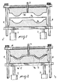
- a process comprising a plurality of steps carried out after arrangement of at least one moulding unit 1 including at least one mould 1a and a related countermould 1b defining at least one moulding cavity 2 between each other.
- Figs. 1 and 2 diagrammatically show a moulding unit 1 in which movements between mould 1a and countermould 1b close to and away from each other are driven by pistons 3 and guided by dowel and guide pins 4 .
- At least one first injector 5 is provided to introduce plastic material in a melted state into the moulding cavity 2 when the mould 1a and countermould 1b are in a closed position.
- the moulding cavity 2 has substantially fixed sizes and shape corresponding to the final sizes and shape of the membrane to be made.
- Said membrane taken as a whole is generally denoted at 6 while 6a specifically identifies the membrane obtained with the process referred to in Figs. 1 to 3.
- the membrane or diaphragm 6 is of the stratified type as it comprises several layers of plastic material.
- At least one first plastic material is provided to be inserted in the moulding cavity 2, which plastic material is of a type chemically resistant to the fluid to be treated, i.e. capable either of resisting the chemically reactive elements present in the fluid - generally a liquid - that the membrane 6 must control or treat, or of withstanding without damages the polluting substances present in the fluid or the dirtiness resulting from treatment of staining fluids.
- Said first plastic material is in fact the material designed to make at least one first layer 7 of the membrane 6 that is directly set in contact with said fluid.
- the first plastic material is selected from special thermoplastic materials having features of resistance to chemical agents: polyolefines, polyamides, polyesters, vinyl resins.
- a polyolefine such as polyethylene (PE) is selected and from the great variety of polyethylenes a high density polyethylene (HDPE) with an ultra high molecular weight (UHMWPE) is selected.
- PE polyethylene
- HDPE high density polyethylene
- UHMWPE ultra high molecular weight
- the high density polyethylene has density values ⁇ greater than 0.940 grams per cubic centimetre and it consists of mainly linear polymethylene chains (-CH 2 -CH 2 -CH 2 -CH 2 -).
- the high density polyethylene having an ultra high molecular weight is a particular high density polyethylene having a molecular weight higher than two million grams per mole, four or more million grams per mole for example.
- the very low friction coefficient is important in order to ensure the maximum efficiency in fluid control and is similar to that of polytetrafluoroethylene (PTFE) or Teflon® that, as well known, is minimum.
- PTFE polytetrafluoroethylene
- Teflon® Teflon®
- HDPE - UHMWPE polyethylene in addition has a chemical resistance still increased with respect to that of high density polyethylene with medium molecular weight (included between fifty thousand and five hundred thousand grams per mole, for example).
- High density polyethylene with an ultra high molecular weight are for example ski soles, bearings, gears, guides for moving mechanical elements.
- HDPE - UHMWPE polyethylene can be obtained by extrusion, exfoliation, sintering of powders, by casting, above all it can also be injection moulded.
- a subsequent step of the process of the present invention it is provided to inject at least one second plastic material of a type adapted to be moulded by injection into the moulding cavity 2 directly, i.e. without interposition of any adhesives or bonding agents, onto the first plastic material, so as to form at least one second layer 8 substantially defining the mechanical performance and duration in time of membrane 6.
- the second plastic material is in fact selected depending on its properties of flexibility, mechanical resistance and resistance to fatigue and in addition it is preferably of such an amount as to form a second layer 8 of greater thickness than the first layer 7.
- the capacity of resistance to chemical agents is not important because under operating conditions the second layer 8 is protected by the first layer 7.
- the second plastic material consists of a thermoplastic elastomer (TPE) selected from santoprene®, pebax®, hytrel®, finaprene®, elastollan®, pibiflex®.
- TPE thermoplastic elastomer
- the selected thermoplastic elastomer (TPE) is santoprene®, trademark of the Advanced Elastomer Systems.
- Santoprene® is a thermoplastic rubber that is distinguishable for its optimal mechanical properties and its easy workability, in particular because it can be easily moulded by injection.
- thermoplastic elastomer TPE
- the first layer 7 is partly preformed out of the moulding cavity 2, i.e. before being inserted into the moulding cavity 2. It is then inserted in the pre-formed shape when the mould 1 a and countermould 1b are in a substantially open position.
- the first layer is preformed out of said moulding cavity in the form of a sheet or film or plate 7a substantially flattened and not shaped.
- the plate 7a is automatically thermoformed by the injection step of the second plastic material, so as to become the first layer 7 with its final shape.
- the second layer 8 be fully shaped before being inserted into the moulding cavity 2.
- first and second layers, 7 and 8 are made definitively integral with each other in the absence of intermediate gluing means.
- the second plastic material is injection-moulded directly onto an adhesive-free surface of the first plastic material, and the second layers is joined adhesive-less to the first layer 7.
- Injection of the second plastic material onto the first is carried out following appropriate modalities compatible with a substantial integrity of the first plastic material.
- injection of the second plastic material is carried out in a manner adapted to bring the first plastic material to temperatures that on an average are close to and lower than the melting temperature.
- Said first plastic material is then characterised by a high viscosity in the melted state and in any case it does not heat in a uniform manner.
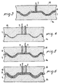
- a mould 1a and a countermould 1b are arranged that are mutually movable in a plurality of moulding positions, so as to form a moulding cavity 2 of varying volume.
- the mould and countermould are relatively movable between a first position (Fig. 4) at which the moulding cavity 2 substantially has the shape and sizes of the first layer 7 alone, and a second position (Fig. 5) at which the moulding cavity 2 has more extended sizes.
- the mould and countermould displacement is obtained through pistons 3.
- the first plastic material too is inserted by injection into the moulding cavity 2 by at least one second injector 9 and therefore the first layer 7 too is integrally made in the moulding cavity 2, which will bring about a further simplification in the operations.
- the second plastic material forming the second layer 8 is then injected after displacement of mould 1a and countermould 1b to said second position.
- the first layer can be made by means of a plate 7a inserted in the moulding cavity 2 when mould 1a and countermould 1b are in a substantially open position (Fig. 1) or alternatively the first layer 7 can be formed by injection (Fig. 4).
- the first layer 7 can be also very thin, in the order of some hundredths of a millimetre, when plate 7a is practically a film.
- the second layer 8 too can be very thin, in the order of some tenths of a millimetre.
- the minimum sizes of the layers are preferably bigger, to facilitate the injection operations, but they are always very reduced, in the order of one millimetre for example for the first layer 7 and some millimetres for the second layer 8.
- both layers 7 and 8 can be widely and readily varied and diversified, and the features of the plastic materials employed can be conveniently selected in view of the foreseen applications.
- a protected membrane 6b formed of three layers and shown in Fig. 8 can also be made, in which the thermoplastic elastomer layer (TPE) is held between two thin layers of HDPE - UHMWPE polyethylene, or other materials from those listed, to protect said thermoplastic elastomer (TPE) on both sides.
- TPE thermoplastic elastomer layer
- step mould 1a and countermould 1b are further separated from each other after injection moulding of the second layer 8, and then repeat the injection moulding operation (Fig. 6) of the first plastic material to form a third layer 10 as well.
- This situation is of immediate accomplishment due to the immediate repetition of the procedures for injection of the first layer 7 and reuse of the first plastic material, although the third layer 10 could also be made of a plastic material different from the first one.
- a protected membrane 6b can be adapted to avoid assembling problems to a user, when the membrane has a flattened shape or when on both sides of same the presence of seepage of corrosive substances is possible.
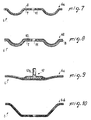
- the membrane 6 made with the process in accordance with the invention can have various shapes.
- a first membrane 6a formed of two layers and having an annular convexity Fig. 7
- a protected membrane 6b formed of three layers Fig. 8
- a flattened membrane 6c Fig. 9
- a cup-shaped membrane 6d Fig. 10
- the first membrane 6a shown in section in Fig. 7 is obtained with a moulding process as shown in Figs. 1 to 3, or the moulding process shown in Figs. 4 and 5, whereas the protected membrane 6b shown in section in Fig. 8 is obtained by the injection moulding process shown in Figs. 4 to 6, still with arrangement of a central hole 11 .
- the central hole 11 can be already made directly in the moulding process and its function is to enable passage, coaxially with the membrane, of a stem for operation of the latter.
- Said drive stem can be fastened for example by means of plates tightening the membrane at opposite faces thereof.
- the shape shown in Fig.9 on the contrary is of the type including means for engagement with said drive stem: partly buried in the second layer 8 - the one determining the mechanical properties of the membrane - is a mushroom-shaped element 12 provided with a tailpiece 12a to be fixed for example by screwing to said drive stem.
- the membrane comprises at least one first layer 7 of a first plastic material which is resistant against the chemical agents that are present in the fluid to be controlled and at least one second layer 8 of a second plastic material defining the mechanical performance of the membrane and preferably having a bigger thickness than that of the first layer.
- the first plastic material forming the first layer is selected from polyolefines, polyamides, polyesters, vinyl resins and preferably and advantageously it is a polyolefine such as high density polyethylene with an ultra high molecular weight (HDPE - UHMWPE).
- polyolefines such as high density polyethylene with an ultra high molecular weight (HDPE - UHMWPE).
- the second plastic material of the second layer is a thermoplastic elastomer (TPE) to be moulded by injection, and selected from santoprene®, pebax®, hytrel®, finaprene®, elastollan®, pibiflex®. Preferably it is santoprene ®.
- TPE thermoplastic elastomer
- first and second layers 7 and 8 are directly in contact with each other adhesive-less being mutually integral in the absence of gluing means.
- the invention achieves important advantages.
- HDPE - UHMWPE high density polyethylene with an ultra high molecular weight
- the new membranes are even ten times less expensive than the membranes where a layer of polytetrafluoroethylene (PTFE) is provided that is joined by special adhesive or gluing means to another plastic material.
- PTFE polytetrafluoroethylene
- the production cycle reaches the maximum simplicity and versatility when the moulding cavity is arranged so as to have a varying volume and all layers are directly and fully made and joined to each other in the same moulding cavity.
- HDPE - UHMWPE polyethylene
- TPE thermoplastic elastomer
- both plastic materials can be injection moulded, thus making it possible to manufacture the whole membrane within the same moulding cavity.
- the invention is susceptible of variations.
- This operation can be carried out either by inserting several plates 7a in the moulding unit of Fig. 1 for example, or by consecutively moulding several layers in the moulding unit of Fig. 4.
- the physical and chemical features and the thickness of the plastic materials forming the layers can be selected and varied depending on the foreseen uses, so as to always obtain optimal functional features.
- thermoplastic elastomers TPE
Landscapes
- Engineering & Computer Science (AREA)
- Mechanical Engineering (AREA)
- General Engineering & Computer Science (AREA)
- Manufacturing & Machinery (AREA)
- Injection Moulding Of Plastics Or The Like (AREA)
- Diaphragms And Bellows (AREA)
- Reciprocating Pumps (AREA)
- Laminated Bodies (AREA)
- Separation Using Semi-Permeable Membranes (AREA)
Abstract
Description
- The invention relates to a process for making a membrane for fluid-control apparatuses, and the membrane obtained with said process.
- The membrane or diaphragm is for example of the type to be used in pumps, compressors, pressure regulators, volume meters, valves.
- It is known that membranes of the above kind are provided in many cases for delivering, metering or directing fluids such as liquids that may also be of the corrosive and/or polluting type.
- Therefore, these membranes must be chemically resistant to these fluids and simultaneously they must be relied on to last a long time and be flexible and strong.
- Said different requirements are met in most cases by arranging membranes of the stratified type and having a first layer of a material resistant to chemical agents and a second layer of a material of appropriate mechanical strength, duration and flexibility.
- FR-A-1 355 765 discloses a membrane of this type wherein the first layer is a film of plastic material selected from polyolefines, polyamides, polyesters or other plastic materials, and the second layer is made of an elastomer like natural or synthetic rubber or a silicone type rubber. The film of plastic material is first shaped to the form of the face of the membrane to be protected and is then applied to the membrane by gluing. However, the film may also be applied by other methods such as overmoulding.
- EP-A-0 732 501 discloses a sensing membrane having the capability of indicating wear conditions prior to failure of the membrane. The membrane comprises at least one layer typically made of a fluorinated resin such as polytetrafluoroethylene (PTFE) marked with the trademark Teflon® and available from Du Pont.
- Polytetrafluoroethylene (PTFE) is preferred due to its great capability of resisting to chemical agents of various types, its tendency not to adhere to the treated materials and fluids and also due to the very reduced coefficient of friction it shows towards the treated fluids.
- The second layer is made of various materials and is generally set with a greater thickness than the first material. Said material is typically an elastomer like Neoprene or Viton®, but may also be a thermoplastic elastomer like a polyurethane elastomer or a polyamide elastomer.
- The two layers are disposed in side by side relationship and made to adhere to each other: the first layer is placed on the membrane side that is in contact with the fluid to control, the second on the other side that is protected by the first one.
- To cause the layers to adhere to each other, an adhesive is previously applied to the contacting surface of the layer of PTFE. The layer of elastomer and the layer of PTFE are then assembled into a pre-form and moulded to a desired shape. If a thermoplastic elastomer is used instead of an uncured elastomer like Neoprene or Viton®, an injection moulding step may take the place of the compression moulding step, as also disclosed in EP-A-1 058 005.
- The above mentioned known art enables membranes or diaphragms to be made of appropriate functional features, but it has some important drawbacks.
- In fact, preparation of said layers is arduous and very expensive: they must all be preformed or shaped in a precise manner and joined together.
- In particular, preforming of the first layer, selected for being adapted to chemically resist reactive/corrosive fluids, and above all gluing of the first layer to the second layer through special adhesives or bonding agents, is difficult and expensive.
- In fact, it is necessary to join materials that are very different from each other, although they all consist of plastic materials, and it is necessary to do it without worsening or altering the physical and chemical features of same.
- In real terms, in order to succeed in joining the polytetrafluoroethylene (PTFE) or Teflon® - that is distinguishable due to its tendency not to adhere to other materials - to another plastic material, special adhesives or bonding agents are required - Chemlock® available from Lord Corporation of Eire, for example - as well as special procedures to join the layers in the presence of the bonding agent and preventing the same from losing their physical and chemical properties. Costs for these operations are so high that attempts have been also made to avoid gluing and merely dispose the layers close to each other.
- In fact, some membranes have a first layer of Teflon ® (PTFE) that is merely disposed tightly close to or pressed against another plastic material.
- It is however apparent that a membrane with the layers joined together can be relied on to a greater extent in terms of reliability and mechanical duration and in particular reduces seepage of the treated fluid between the membranes and therefore corrosion of the second layer that is unsuitable to resist chemical agents or polluting substances.
- The material of the first layer may also be a UHMWPE (ultra high molecular weight polyethylene) (MODERN PLASTICS; HARPER, C. A.: "Modern Plastics Handbook" 2000, McGraw-Hill XP002271941), wherein the high molecular weight imparts outstanding abrasion resistance and other excellent mechanical properties. UHMWPE is often processed as a fine powder that can be ram extruded or compression moulded, although an injection-moulding grade is marketed by Hoechst.
- Further, EP-A-0 183 342 discloses a diaphragm valve in which the membrane is made of a single layer of material injection-moulded on a rigid pressure element in form of a shaped piston head. The portion of the membrane connected to the rigid pressure element is thus made rigid with this body, so that the flexing properties of the membrane are greatly reduced.
- There is therefore an unresolved technical problem consisting in how to make reliable membranes at low costs.
- Under this situation the technical task underlying the present invention is to conceive a process and a membrane capable of obviating the mentioned drawbacks and solving said technical problem.
- The technical task is achieved by a process for making a membrane for fluid-control apparatuses and by a membrane obtained with said process, as claimed in the appended
independent Claims 1 and 9, respectively. - Preferred embodiments are recited in the dependent Claims.
- Further features and advantages of the invention will become more apparent from the following detailed description of some preferred embodiments of the invention, with reference to the accompanying drawings, in which:
- Fig. 1 shows a first step of carrying out the process in accordance with the invention, with insertion of a first laminar and not preformed plastic material between a mould and a countermould in an open position;
- Fig. 2 shows a second step of the process, in which the mould and countermould are closed on the first plastic material;
- Fig. 3 shows a third step in which a second plastic material is injected;
- Fig. 4 is a further embodiment of the process in a first step during which a first layer is moulded;
- Fig. 5 shows a subsequent step to that seen in Fig. 4;
- Fig. 6 shows a further step, subsequent to that in Fig. 5;
- Fig. 7 is a section view of a membrane made up of two layers obtained with the process shown in Figs. 1 to 3, provided with a central opening;
- Fig. 8 is a section view of a membrane similar to that in Fig. 7 but consisting of three layers and obtained with the process seen in Figs. 4 to 6;
- Fig. 9 shows a two-layer membrane provided with a substantially flattened shape and centrally having a metal insert; and
- Fig. 10 shows a substantially cup-shaped two-layer membrane.
- In accordance with the invention, it is provided a process comprising a plurality of steps carried out after arrangement of at least one moulding unit 1 including at least one mould 1a and a related countermould 1b defining at least one
moulding cavity 2 between each other. - Figs. 1 and 2 diagrammatically show a moulding unit 1 in which movements between mould 1a and countermould 1b close to and away from each other are driven by
pistons 3 and guided by dowel andguide pins 4. - At least one
first injector 5 is provided to introduce plastic material in a melted state into themoulding cavity 2 when the mould 1a and countermould 1b are in a closed position. - In the preferred embodiment shown in Figs. 1 to 3 the
moulding cavity 2 has substantially fixed sizes and shape corresponding to the final sizes and shape of the membrane to be made. Said membrane taken as a whole is generally denoted at 6 while 6a specifically identifies the membrane obtained with the process referred to in Figs. 1 to 3. - The membrane or diaphragm 6 is of the stratified type as it comprises several layers of plastic material.
- In accordance with a step of the process, at least one first plastic material is provided to be inserted in the
moulding cavity 2, which plastic material is of a type chemically resistant to the fluid to be treated, i.e. capable either of resisting the chemically reactive elements present in the fluid - generally a liquid - that the membrane 6 must control or treat, or of withstanding without damages the polluting substances present in the fluid or the dirtiness resulting from treatment of staining fluids. - Said first plastic material is in fact the material designed to make at least one
first layer 7 of the membrane 6 that is directly set in contact with said fluid. - The first plastic material is selected from special thermoplastic materials having features of resistance to chemical agents: polyolefines, polyamides, polyesters, vinyl resins.
- Preferably a polyolefine such as polyethylene (PE) is selected and from the great variety of polyethylenes a high density polyethylene (HDPE) with an ultra high molecular weight (UHMWPE) is selected.
- The high density polyethylene (HDPE) has density values δ greater than 0.940 grams per cubic centimetre and it consists of mainly linear polymethylene chains (-CH2-CH2-CH2-CH2-).
- It has a great chemical inertia and in particular is chemically resistant to acids, alkaline solutions, saline solutions, water, alcohol, esters, oil, petrol. At room temperature practically it is not attackable by any reactant and is not soluble in any solvent. Only above 90°C it can be attacked by aromatic and chlorinated solvents.
- In addition, it also has optimal mechanical, technical and electric properties. Furthermore the high density polyethylene having an ultra high molecular weight (UHMWPE i.e. as above said "Ultra High Molecular Weight Poly-Ethylene") is a particular high density polyethylene having a molecular weight higher than two million grams per mole, four or more million grams per mole for example.
- Among other things, it is distinguishable for an exceptional resistance to wear and a very low coefficient of friction by sliding.
- The very low friction coefficient is important in order to ensure the maximum efficiency in fluid control and is similar to that of polytetrafluoroethylene (PTFE) or Teflon® that, as well known, is minimum.
- HDPE - UHMWPE polyethylene in addition has a chemical resistance still increased with respect to that of high density polyethylene with medium molecular weight (included between fifty thousand and five hundred thousand grams per mole, for example).
- It also has a maximum dimensional stability up to temperatures very close to the melting temperature and a high viscosity in the melted state as well.
- Presently made of high density polyethylene with an ultra high molecular weight are for example ski soles, bearings, gears, guides for moving mechanical elements.
- HDPE - UHMWPE polyethylene can be obtained by extrusion, exfoliation, sintering of powders, by casting, above all it can also be injection moulded.
- In a subsequent step of the process of the present invention it is provided to inject at least one second plastic material of a type adapted to be moulded by injection into the
moulding cavity 2 directly, i.e. without interposition of any adhesives or bonding agents, onto the first plastic material, so as to form at least onesecond layer 8 substantially defining the mechanical performance and duration in time of membrane 6. - The second plastic material is in fact selected depending on its properties of flexibility, mechanical resistance and resistance to fatigue and in addition it is preferably of such an amount as to form a
second layer 8 of greater thickness than thefirst layer 7. - The capacity of resistance to chemical agents is not important because under operating conditions the
second layer 8 is protected by thefirst layer 7. - The second plastic material consists of a thermoplastic elastomer (TPE) selected from santoprene®, pebax®, hytrel®, finaprene®, elastollan®, pibiflex®. Preferably, the selected thermoplastic elastomer (TPE) is santoprene®, trademark of the Advanced Elastomer Systems.
- Santoprene® is a thermoplastic rubber that is distinguishable for its optimal mechanical properties and its easy workability, in particular because it can be easily moulded by injection.
- The injection phase of the thermoplastic elastomer (TPE) directly onto the first plastic material without application of an adhesive achieves important results.
- In the case shown in Figs. 1 to 3, the
first layer 7 is partly preformed out of themoulding cavity 2, i.e. before being inserted into themoulding cavity 2. It is then inserted in the pre-formed shape when the mould 1 a and countermould 1b are in a substantially open position. In particular, the first layer is preformed out of said moulding cavity in the form of a sheet or film orplate 7a substantially flattened and not shaped. - Under this situation the
plate 7a is automatically thermoformed by the injection step of the second plastic material, so as to become thefirst layer 7 with its final shape. - However it is not to be excluded that the
second layer 8 be fully shaped before being inserted into themoulding cavity 2. - At all events, formation of the
second layer 8 by injection of the second plastic material onto the first one according to the invention gives rise to a perfect welding between the twolayers - Practically the first and second layers, 7 and 8, are made definitively integral with each other in the absence of intermediate gluing means.
- The second plastic material is injection-moulded directly onto an adhesive-free surface of the first plastic material, and the second layers is joined adhesive-less to the
first layer 7. - Injection of the second plastic material onto the first is carried out following appropriate modalities compatible with a substantial integrity of the first plastic material.
- In particular, injection of the second plastic material, obviously in a melted state, is carried out in a manner adapted to bring the first plastic material to temperatures that on an average are close to and lower than the melting temperature. This does not necessarily mean that the injection temperature should be very reduced: it is for example necessary to consider the moulding conditions that can be varied, the thickness of the layers and the cooling speed of the plastic material in the moulds.
- Said first plastic material is then characterised by a high viscosity in the melted state and in any case it does not heat in a uniform manner.
- In addition an appropriate heating of the surface in contact with the second plastic material is wished in order to join the two layers in a stable manner.
- The optimal temperatures and moulding conditions in any case can be easily identified by means of normal moulding tests well known by all technicians in the sector.
- In carrying out the process shown in Figs. 4 to 6, a mould 1a and a countermould 1b are arranged that are mutually movable in a plurality of moulding positions, so as to form a
moulding cavity 2 of varying volume. - For example, the mould and countermould are relatively movable between a first position (Fig. 4) at which the
moulding cavity 2 substantially has the shape and sizes of thefirst layer 7 alone, and a second position (Fig. 5) at which themoulding cavity 2 has more extended sizes. - The mould and countermould displacement is obtained through
pistons 3. Under this situation the first plastic material too is inserted by injection into themoulding cavity 2 by at least onesecond injector 9 and therefore thefirst layer 7 too is integrally made in themoulding cavity 2, which will bring about a further simplification in the operations. - The second plastic material forming the
second layer 8 is then injected after displacement of mould 1a and countermould 1b to said second position. - In this way a membrane similar to and made with the process of Figs. 1 to 3 and
- Fig. 7 and identified by 6a is obtained.
- Depending on the final features wished for the membrane, the first layer can be made by means of a
plate 7a inserted in themoulding cavity 2 when mould 1a and countermould 1b are in a substantially open position (Fig. 1) or alternatively thefirst layer 7 can be formed by injection (Fig. 4). - For example, in the case shown in Figs. 1 to 3, the
first layer 7 can be also very thin, in the order of some hundredths of a millimetre, whenplate 7a is practically a film. Thesecond layer 8 too can be very thin, in the order of some tenths of a millimetre. - With the embodiment shown in Figs. 4 and 5 the minimum sizes of the layers are preferably bigger, to facilitate the injection operations, but they are always very reduced, in the order of one millimetre for example for the
first layer 7 and some millimetres for thesecond layer 8. - Bigger sizes than the minimum ones can be selected with the greatest freedom and the process in accordance with the invention has a great flexibility and enables membranes adapted to the most different applications to be made.
- In fact, the thickness of both
layers - In addition, by providing a mould 1a and countermould 1b mutually movable, a protected membrane 6b formed of three layers and shown in Fig. 8 can also be made, in which the thermoplastic elastomer layer (TPE) is held between two thin layers of HDPE - UHMWPE polyethylene, or other materials from those listed, to protect said thermoplastic elastomer (TPE) on both sides.
- It is sufficient to provide a third step for the movable moulds, in which step mould 1a and countermould 1b are further separated from each other after injection moulding of the
second layer 8, and then repeat the injection moulding operation (Fig. 6) of the first plastic material to form athird layer 10 as well. - This situation is of immediate accomplishment due to the immediate repetition of the procedures for injection of the
first layer 7 and reuse of the first plastic material, although thethird layer 10 could also be made of a plastic material different from the first one. - A protected membrane 6b can be adapted to avoid assembling problems to a user, when the membrane has a flattened shape or when on both sides of same the presence of seepage of corrosive substances is possible.
- As highlighted in the figures, the membrane 6 made with the process in accordance with the invention can have various shapes.
- As shown in Figs. 7 to 10, for example, i.e. a first membrane 6a formed of two layers and having an annular convexity (Fig. 7), a protected membrane 6b formed of three layers (Fig. 8) or also a flattened membrane 6c (Fig. 9) or a cup-shaped membrane 6d (Fig. 10).
- The first membrane 6a shown in section in Fig. 7 is obtained with a moulding process as shown in Figs. 1 to 3, or the moulding process shown in Figs. 4 and 5, whereas the protected membrane 6b shown in section in Fig. 8 is obtained by the injection moulding process shown in Figs. 4 to 6, still with arrangement of a
central hole 11. - The
central hole 11 can be already made directly in the moulding process and its function is to enable passage, coaxially with the membrane, of a stem for operation of the latter. Said drive stem can be fastened for example by means of plates tightening the membrane at opposite faces thereof. - The shape shown in Fig.9 on the contrary is of the type including means for engagement with said drive stem: partly buried in the second layer 8 - the one determining the mechanical properties of the membrane - is a mushroom-shaped
element 12 provided with a tailpiece 12a to be fixed for example by screwing to said drive stem. - At all events the membrane comprises at least one
first layer 7 of a first plastic material which is resistant against the chemical agents that are present in the fluid to be controlled and at least onesecond layer 8 of a second plastic material defining the mechanical performance of the membrane and preferably having a bigger thickness than that of the first layer. - The first plastic material forming the first layer is selected from polyolefines, polyamides, polyesters, vinyl resins and preferably and advantageously it is a polyolefine such as high density polyethylene with an ultra high molecular weight (HDPE - UHMWPE).
- The second plastic material of the second layer is a thermoplastic elastomer (TPE) to be moulded by injection, and selected from santoprene®, pebax®, hytrel®, finaprene®, elastollan®, pibiflex®. Preferably it is santoprene ®.
- In addition, the first and
second layers - The invention achieves important advantages.
- In fact it allows membranes of full liability to be manufactured in a simple manner, in which the layers are perfectly formed and joined together in a stable manner also without use of adhesives or bonding agents.
- In particular, high density polyethylene with an ultra high molecular weight (HDPE - UHMWPE) has appeared to be quite satisfactory in terms of chemical resistance to most of the treated fluids, minimum coefficient of friction, duration and mechanical properties.
- Above all, choice of the materials, simplicity of the production cycle and absence of gluing means and operations, as well as possibility of completely avoiding thermoforming operations carried out on the layers before the injection-moulding step lead to manufacture of membranes much cheaper as compared with known membranes in which the layers are joined to each other.
- There is a great money saving: the new membranes are even ten times less expensive than the membranes where a layer of polytetrafluoroethylene (PTFE) is provided that is joined by special adhesive or gluing means to another plastic material. The production cycle reaches the maximum simplicity and versatility when the moulding cavity is arranged so as to have a varying volume and all layers are directly and fully made and joined to each other in the same moulding cavity.
- Then combination of said polyethylene (HDPE - UHMWPE) with a thermoplastic elastomer (TPE) offers the maximum compatibility between the layers and the possibility of forming all layers by injection moulding.
- In fact, both plastic materials can be injection moulded, thus making it possible to manufacture the whole membrane within the same moulding cavity.
- The invention is susceptible of variations.
- For example many layers can be made if the membrane properties are required to be increased.
- This operation can be carried out either by inserting
several plates 7a in the moulding unit of Fig. 1 for example, or by consecutively moulding several layers in the moulding unit of Fig. 4. - It is then pointed out that in the process in accordance with the invention the physical and chemical features and the thickness of the plastic materials forming the layers can be selected and varied depending on the foreseen uses, so as to always obtain optimal functional features.
- For example, it is to be noted that the high density polyethylene itself with an ultra high molecular weight is produced with several different additives and molecular weights and there is also a wide choice in the field of thermoplastic elastomers (TPE).
Claims (11)
- A process for making a membrane for fluid control apparatuses, comprising the steps of making at least one first layer (7) of a membrane (6) with a first plastic material chemically resistant to said fluid, making at least one second layer (8) of a second plastic material mainly defining the mechanical performance of said membrane (6), and making said layers (7, 8) integral with each other, wherein said first plastic material is selected from polyolefines, polyamides, polyesters, vinyl resins and said second plastic material is an elastomer,
characterised in that said second plastic material is a thermoplastic elastomer (TPE) and in that said thermoplastic elastomer (TPE) is injection-moulded directly onto an adhesive-free surface of said first plastic material inserted in a moulding cavity (2) of an injection mould (1a, 1b), thereby forming at least one second layer (8) joined adhesive-less to said first layer (7). - A process as claimed in claim 1, characterised in that injection-moulding of said second plastic material is carried out at temperatures bringing said first plastic material to average temperatures close to, and lower than, the melting temperature of said first plastic material.
- A process as claimed in claim 1 or 2, characterised in that it comprises a first step of injection-moulding said first layer (7), and a second step of injection-moulding said second layer (8) over said first layer (7).
- A process as claimed in claim 3, characterised in that a third layer (10) of plastic material is injection-moulded directly on said second layer (8).
- A process as claimed in one or more of the preceding claims, characterised in that said first plastic material is polyethylene (PE), preferably a high density polyethylene (HDPE) with an ultrahigh molecular weight (UHMWPE).
- A process as claimed in claim 1, characterised in that said first layer (7) is in the form of a flattened sheet or plate (7a) of said first plastic material and is inserted in said form into said moulding cavity (2), and in that said sheet or plate (7a) is thermoformed to its final shape by said injection-moulding of said second plastic material in said moulding cavity (2).
- A process as claimed in claim 4, characterised in that said third layer (10) is of the same plastic material as the material forming said first layer (7).
- A membrane for fluid control apparatuses, comprising at least one first layer (7) of a first plastic material chemically resistant to said fluid, and at least one second layer (8) of a second plastic material mainly defining the mechanical performance of the membrane, said layers (7, 8) being integral with each other, wherein said first plastic material is selected from polyolefines, polyamides, polyesters, vinyl resins, and said second plastic material is an elastomer,
characterised in that said second layer (8) is made of a thermoplastic elastomer (TPE) adapted to be injection-moulded, said thermoplastic elastomer being joined adhesive-less with said first plastic material of said first layer (7). - A membrane as claimed in claim 8, characterised in that it further comprises a third layer (10) of a plastic material adapted to be injection moulded, said third layer (10) being joined adhesive-less with said second layer (8) at the side thereof opposite to said first layer (7).
- A membrane as claimed in claim 9, characterised in that said third layer (10) is made of the same plastic material as the plastic material forming said first layer (7).
- A membrane as claimed in claim 8, characterised in that said first layer (7) is made of high density polyethylene (HDPE) with an ultrahigh molecular weight (UHMWPE).
Priority Applications (5)
| Application Number | Priority Date | Filing Date | Title |
|---|---|---|---|
| EP20030425624 EP1518656B1 (en) | 2003-09-26 | 2003-09-26 | Process for making a membrane for fluid-control apparatuses, and membrane made thereby |
| DE2003607850 DE60307850T2 (en) | 2003-09-26 | 2003-09-26 | Process for the preparation of a membrane for fluid influencing devices, and membrane produced thereafter |
| AT03425624T ATE337152T1 (en) | 2003-09-26 | 2003-09-26 | METHOD FOR PRODUCING A MEMBRANE FOR FLUID INFLUENCING DEVICES, AND MEMBRANE PRODUCED THEREFROM |
| ES03425624T ES2274194T3 (en) | 2003-09-26 | 2003-09-26 | MANUFACTURING PROCESS OF A MEMBRANE FOR FLUID CONTROL EQUIPMENT AND MEMBRANE MANUFACTURED IN ACCORDANCE WITH THE PROCEDURE. |
| US10/947,662 US20050110190A1 (en) | 2003-09-26 | 2004-09-23 | Process for making a membrane for fluid-control apparatuses, and membrane made thereby |
Applications Claiming Priority (1)
| Application Number | Priority Date | Filing Date | Title |
|---|---|---|---|
| EP20030425624 EP1518656B1 (en) | 2003-09-26 | 2003-09-26 | Process for making a membrane for fluid-control apparatuses, and membrane made thereby |
Publications (2)
| Publication Number | Publication Date |
|---|---|
| EP1518656A1 EP1518656A1 (en) | 2005-03-30 |
| EP1518656B1 true EP1518656B1 (en) | 2006-08-23 |
Family
ID=34178706
Family Applications (1)
| Application Number | Title | Priority Date | Filing Date |
|---|---|---|---|
| EP20030425624 Expired - Lifetime EP1518656B1 (en) | 2003-09-26 | 2003-09-26 | Process for making a membrane for fluid-control apparatuses, and membrane made thereby |
Country Status (5)
| Country | Link |
|---|---|
| US (1) | US20050110190A1 (en) |
| EP (1) | EP1518656B1 (en) |
| AT (1) | ATE337152T1 (en) |
| DE (1) | DE60307850T2 (en) |
| ES (1) | ES2274194T3 (en) |
Cited By (1)
| Publication number | Priority date | Publication date | Assignee | Title |
|---|---|---|---|---|
| US20260009379A1 (en) * | 2024-07-04 | 2026-01-08 | Joachim Oehrle | Composite diaphragm for diaphragm pump |
Families Citing this family (18)
| Publication number | Priority date | Publication date | Assignee | Title |
|---|---|---|---|---|
| ES2247956B1 (en) * | 2005-10-07 | 2007-05-16 | Santos Jimenez Fuentes | MANUFACTURING SYSTEM OF COATING PLATES AND RESULTING PLATES. |
| DE102005060167B4 (en) * | 2005-12-01 | 2016-04-07 | Aptar Dortmund Gmbh | dispenser |
| EP1892414B1 (en) * | 2006-07-21 | 2009-10-21 | ULMAN Dichtungstechnik GmbH | Composite membrane |
| US7410608B1 (en) * | 2007-09-19 | 2008-08-12 | Rectorseal Corporation | Methods for manufacturing a diaphragm for an air admittance valve |
| ES2776709T3 (en) | 2007-11-21 | 2020-07-31 | Smith & Nephew | Wound dressing |
| GB0723855D0 (en) | 2007-12-06 | 2008-01-16 | Smith & Nephew | Apparatus and method for wound volume measurement |
| DE102009018214A1 (en) * | 2009-04-21 | 2010-10-28 | Zahoransky Ag | Shaping machine, for shaping film material into blister packaging, has an injection molding unit coupled to one of the dies |
| GB201015656D0 (en) | 2010-09-20 | 2010-10-27 | Smith & Nephew | Pressure control apparatus |
| US9067003B2 (en) | 2011-05-26 | 2015-06-30 | Kalypto Medical, Inc. | Method for providing negative pressure to a negative pressure wound therapy bandage |
| KR101221853B1 (en) | 2011-08-19 | 2013-01-15 | 주식회사리온 | Manufacturing methode of membrane for chemical mechanical polishing and membrane for chemical mechanical polishing using the same |
| US9084845B2 (en) | 2011-11-02 | 2015-07-21 | Smith & Nephew Plc | Reduced pressure therapy apparatuses and methods of using same |
| US9901664B2 (en) | 2012-03-20 | 2018-02-27 | Smith & Nephew Plc | Controlling operation of a reduced pressure therapy system based on dynamic duty cycle threshold determination |
| US9427505B2 (en) | 2012-05-15 | 2016-08-30 | Smith & Nephew Plc | Negative pressure wound therapy apparatus |
| GB2516670A (en) * | 2013-07-29 | 2015-02-04 | Atlas Genetics Ltd | Fluid control device and method of manufacture |
| AU2015370583B2 (en) | 2014-12-22 | 2020-08-20 | Smith & Nephew Plc | Negative pressure wound therapy apparatus and methods |
| CN110951145B (en) * | 2019-12-18 | 2022-09-09 | 大韩道恩高分子材料(上海)有限公司 | Injection molding grade ultra-high molecular weight polyethylene material and preparation method and application thereof |
| DE102020128923A1 (en) * | 2020-11-03 | 2022-05-05 | Gemü Gebr. Müller Apparatebau Gmbh & Co. Kommanditgesellschaft | Method of making a diaphragm for a diaphragm valve and diaphragm |
| DE102023117879A1 (en) * | 2023-07-06 | 2025-01-09 | Prominent Gmbh | dosing membrane |
Family Cites Families (15)
| Publication number | Priority date | Publication date | Assignee | Title |
|---|---|---|---|---|
| FR1355765A (en) * | 1963-02-08 | 1964-03-20 | Jaeger Ets Ed | Improvement in deformable membranes |
| US4281070A (en) * | 1980-01-07 | 1981-07-28 | The Polymer Corporation | Melt processable UHMWPE |
| JPS59222676A (en) * | 1983-06-01 | 1984-12-14 | Nippon Denso Co Ltd | Diaphragm device |
| JPS60155428A (en) * | 1984-01-25 | 1985-08-15 | Nippon Petrochem Co Ltd | Manufacture of laminated sheet or laminated film |
| GB8421787D0 (en) * | 1984-08-29 | 1984-10-03 | Saunders Valve Co Ltd | Diaphragm valve |
| KR960007011B1 (en) * | 1988-01-29 | 1996-05-27 | 미쓰이세끼유 가가꾸 고오교오 가부시끼가이샤 | Laminated molded article and manufacturing method |
| TW232671B (en) * | 1990-01-16 | 1994-10-21 | Idemitsu Petrochemical Co | |
| JP3051487B2 (en) * | 1991-04-03 | 2000-06-12 | 三井化学株式会社 | Ultra-high molecular weight polyethylene shrink pipe, method and apparatus for producing the same |
| JP2726014B2 (en) * | 1995-01-06 | 1998-03-11 | 株式会社ワイ・テイ・エス | Diaphragm assembly and method of manufacturing the same |
| US5560279A (en) * | 1995-03-16 | 1996-10-01 | W. L. Gore & Associates, Inc. | Pre-failure sensing diaphragm |
| US6230609B1 (en) * | 1999-06-03 | 2001-05-15 | Norton Performance Plastics Corporation | Fluoropolymer diaphragm with integral attachment device |
| US6746637B1 (en) * | 1999-11-15 | 2004-06-08 | Westinghouse Air Brake Technologies Corporation | Process for making chemical resistant pump diaphragm |
| US6824139B2 (en) * | 2000-09-15 | 2004-11-30 | Hewlett-Packard Development Company, L.P. | Overmolded elastomeric diaphragm pump for pressurization in inkjet printing systems |
| US6641769B1 (en) * | 2001-03-27 | 2003-11-04 | Global Polymer Industries, Inc. | Method of forming composite ultrahigh molecular weight polyethylene material |
| US6740390B2 (en) * | 2001-04-25 | 2004-05-25 | Guardian Industries Corp. | Applique for A-pillar area of vehicle |
-
2003
- 2003-09-26 EP EP20030425624 patent/EP1518656B1/en not_active Expired - Lifetime
- 2003-09-26 AT AT03425624T patent/ATE337152T1/en not_active IP Right Cessation
- 2003-09-26 ES ES03425624T patent/ES2274194T3/en not_active Expired - Lifetime
- 2003-09-26 DE DE2003607850 patent/DE60307850T2/en not_active Expired - Fee Related
-
2004
- 2004-09-23 US US10/947,662 patent/US20050110190A1/en not_active Abandoned
Cited By (1)
| Publication number | Priority date | Publication date | Assignee | Title |
|---|---|---|---|---|
| US20260009379A1 (en) * | 2024-07-04 | 2026-01-08 | Joachim Oehrle | Composite diaphragm for diaphragm pump |
Also Published As
| Publication number | Publication date |
|---|---|
| EP1518656A1 (en) | 2005-03-30 |
| US20050110190A1 (en) | 2005-05-26 |
| ES2274194T3 (en) | 2007-05-16 |
| DE60307850D1 (en) | 2006-10-05 |
| DE60307850T2 (en) | 2007-04-12 |
| ATE337152T1 (en) | 2006-09-15 |
Similar Documents
| Publication | Publication Date | Title |
|---|---|---|
| EP1518656B1 (en) | Process for making a membrane for fluid-control apparatuses, and membrane made thereby | |
| CN1111660C (en) | Plastic coated valve rotor and method of manufacture | |
| EP2755703B1 (en) | Piston seal | |
| US6746637B1 (en) | Process for making chemical resistant pump diaphragm | |
| EP1076788A1 (en) | Valve gasket formed of composite materials and process | |
| US5622097A (en) | Hydraulic piston machine | |
| GB2519844A (en) | A sealing diaphragm and methods of manufacturing said diaphragm | |
| WO2008005654A2 (en) | Dispenser and piston for dispensing a liquid material and method of making a piston | |
| US11426511B2 (en) | Microflow restrictor assembly and methods of making the same | |
| EP0679224A1 (en) | Hydraulic machine and method for assembling a piston and slider shoe unit. | |
| EP2210024A1 (en) | Elastomeric valve | |
| US8226318B1 (en) | Tube with integral elastomeric applicator and method of manufacture therefor | |
| EP1834119B1 (en) | Stopcock closure plug | |
| WO2008042316A2 (en) | Fluid operated device with improved seal valve | |
| JPH10156874A (en) | Composite resin molding and its production | |
| JP4094086B2 (en) | Method of forming seal member for return plate in linear guide bearing | |
| CN1617993A (en) | Performance polymer film insert molding for fluid control devices | |
| WO2015143315A1 (en) | Lip seal having a base member and a lip member | |
| KR100333165B1 (en) | Constitution Of Valve Packing And Process For Preparing Thereof | |
| GB2494683A (en) | A piston seal for a syringe or syringe pump | |
| WO2010132374A2 (en) | Polymer-metallic reagent head | |
| NZ556525A (en) | Stopcock closure plug made from theroplastic elastomer (TPE) | |
| HK1108474B (en) | Stopcock closure plug |
Legal Events
| Date | Code | Title | Description |
|---|---|---|---|
| PUAI | Public reference made under article 153(3) epc to a published international application that has entered the european phase |
Free format text: ORIGINAL CODE: 0009012 |
|
| 17P | Request for examination filed |
Effective date: 20040805 |
|
| AK | Designated contracting states |
Kind code of ref document: A1 Designated state(s): AT BE BG CH CY CZ DE DK EE ES FI FR GB GR HU IE IT LI LU MC NL PT RO SE SI SK TR |
|
| AX | Request for extension of the european patent |
Extension state: AL LT LV MK |
|
| AKX | Designation fees paid |
Designated state(s): AT BE BG CH CY CZ DE DK EE ES FI FR GB GR HU IE IT LI LU MC NL PT RO SE SI SK TR |
|
| GRAP | Despatch of communication of intention to grant a patent |
Free format text: ORIGINAL CODE: EPIDOSNIGR1 |
|
| GRAS | Grant fee paid |
Free format text: ORIGINAL CODE: EPIDOSNIGR3 |
|
| GRAA | (expected) grant |
Free format text: ORIGINAL CODE: 0009210 |
|
| AK | Designated contracting states |
Kind code of ref document: B1 Designated state(s): AT BE BG CH CY CZ DE DK EE ES FI FR GB GR HU IE IT LI LU MC NL PT RO SE SI SK TR |
|
| PG25 | Lapsed in a contracting state [announced via postgrant information from national office to epo] |
Ref country code: NL Free format text: LAPSE BECAUSE OF FAILURE TO SUBMIT A TRANSLATION OF THE DESCRIPTION OR TO PAY THE FEE WITHIN THE PRESCRIBED TIME-LIMIT Effective date: 20060823 Ref country code: CZ Free format text: LAPSE BECAUSE OF FAILURE TO SUBMIT A TRANSLATION OF THE DESCRIPTION OR TO PAY THE FEE WITHIN THE PRESCRIBED TIME-LIMIT Effective date: 20060823 Ref country code: LI Free format text: LAPSE BECAUSE OF FAILURE TO SUBMIT A TRANSLATION OF THE DESCRIPTION OR TO PAY THE FEE WITHIN THE PRESCRIBED TIME-LIMIT Effective date: 20060823 Ref country code: AT Free format text: LAPSE BECAUSE OF FAILURE TO SUBMIT A TRANSLATION OF THE DESCRIPTION OR TO PAY THE FEE WITHIN THE PRESCRIBED TIME-LIMIT Effective date: 20060823 Ref country code: BE Free format text: LAPSE BECAUSE OF FAILURE TO SUBMIT A TRANSLATION OF THE DESCRIPTION OR TO PAY THE FEE WITHIN THE PRESCRIBED TIME-LIMIT Effective date: 20060823 Ref country code: FI Free format text: LAPSE BECAUSE OF FAILURE TO SUBMIT A TRANSLATION OF THE DESCRIPTION OR TO PAY THE FEE WITHIN THE PRESCRIBED TIME-LIMIT Effective date: 20060823 Ref country code: SI Free format text: LAPSE BECAUSE OF FAILURE TO SUBMIT A TRANSLATION OF THE DESCRIPTION OR TO PAY THE FEE WITHIN THE PRESCRIBED TIME-LIMIT Effective date: 20060823 Ref country code: RO Free format text: LAPSE BECAUSE OF FAILURE TO SUBMIT A TRANSLATION OF THE DESCRIPTION OR TO PAY THE FEE WITHIN THE PRESCRIBED TIME-LIMIT Effective date: 20060823 Ref country code: CH Free format text: LAPSE BECAUSE OF FAILURE TO SUBMIT A TRANSLATION OF THE DESCRIPTION OR TO PAY THE FEE WITHIN THE PRESCRIBED TIME-LIMIT Effective date: 20060823 Ref country code: SK Free format text: LAPSE BECAUSE OF FAILURE TO SUBMIT A TRANSLATION OF THE DESCRIPTION OR TO PAY THE FEE WITHIN THE PRESCRIBED TIME-LIMIT Effective date: 20060823 |
|
| REG | Reference to a national code |
Ref country code: GB Ref legal event code: FG4D |
|
| REG | Reference to a national code |
Ref country code: CH Ref legal event code: EP |
|
| REG | Reference to a national code |
Ref country code: IE Ref legal event code: FG4D |
|
| PG25 | Lapsed in a contracting state [announced via postgrant information from national office to epo] |
Ref country code: IE Free format text: LAPSE BECAUSE OF NON-PAYMENT OF DUE FEES Effective date: 20060926 |
|
| PG25 | Lapsed in a contracting state [announced via postgrant information from national office to epo] |
Ref country code: MC Free format text: LAPSE BECAUSE OF NON-PAYMENT OF DUE FEES Effective date: 20060930 |
|
| REF | Corresponds to: |
Ref document number: 60307850 Country of ref document: DE Date of ref document: 20061005 Kind code of ref document: P |
|
| PG25 | Lapsed in a contracting state [announced via postgrant information from national office to epo] |
Ref country code: BG Free format text: LAPSE BECAUSE OF FAILURE TO SUBMIT A TRANSLATION OF THE DESCRIPTION OR TO PAY THE FEE WITHIN THE PRESCRIBED TIME-LIMIT Effective date: 20061123 Ref country code: SE Free format text: LAPSE BECAUSE OF FAILURE TO SUBMIT A TRANSLATION OF THE DESCRIPTION OR TO PAY THE FEE WITHIN THE PRESCRIBED TIME-LIMIT Effective date: 20061123 Ref country code: DK Free format text: LAPSE BECAUSE OF FAILURE TO SUBMIT A TRANSLATION OF THE DESCRIPTION OR TO PAY THE FEE WITHIN THE PRESCRIBED TIME-LIMIT Effective date: 20061123 |
|
| PG25 | Lapsed in a contracting state [announced via postgrant information from national office to epo] |
Ref country code: PT Free format text: LAPSE BECAUSE OF FAILURE TO SUBMIT A TRANSLATION OF THE DESCRIPTION OR TO PAY THE FEE WITHIN THE PRESCRIBED TIME-LIMIT Effective date: 20070125 |
|
| NLV1 | Nl: lapsed or annulled due to failure to fulfill the requirements of art. 29p and 29m of the patents act | ||
| REG | Reference to a national code |
Ref country code: CH Ref legal event code: PL |
|
| ET | Fr: translation filed | ||
| REG | Reference to a national code |
Ref country code: ES Ref legal event code: FG2A Ref document number: 2274194 Country of ref document: ES Kind code of ref document: T3 |
|
| PLBE | No opposition filed within time limit |
Free format text: ORIGINAL CODE: 0009261 |
|
| STAA | Information on the status of an ep patent application or granted ep patent |
Free format text: STATUS: NO OPPOSITION FILED WITHIN TIME LIMIT |
|
| 26N | No opposition filed |
Effective date: 20070524 |
|
| PG25 | Lapsed in a contracting state [announced via postgrant information from national office to epo] |
Ref country code: GR Free format text: LAPSE BECAUSE OF FAILURE TO SUBMIT A TRANSLATION OF THE DESCRIPTION OR TO PAY THE FEE WITHIN THE PRESCRIBED TIME-LIMIT Effective date: 20061124 |
|
| PG25 | Lapsed in a contracting state [announced via postgrant information from national office to epo] |
Ref country code: EE Free format text: LAPSE BECAUSE OF FAILURE TO SUBMIT A TRANSLATION OF THE DESCRIPTION OR TO PAY THE FEE WITHIN THE PRESCRIBED TIME-LIMIT Effective date: 20060823 |
|
| PG25 | Lapsed in a contracting state [announced via postgrant information from national office to epo] |
Ref country code: TR Free format text: LAPSE BECAUSE OF FAILURE TO SUBMIT A TRANSLATION OF THE DESCRIPTION OR TO PAY THE FEE WITHIN THE PRESCRIBED TIME-LIMIT Effective date: 20060823 Ref country code: LU Free format text: LAPSE BECAUSE OF NON-PAYMENT OF DUE FEES Effective date: 20060926 Ref country code: HU Free format text: LAPSE BECAUSE OF FAILURE TO SUBMIT A TRANSLATION OF THE DESCRIPTION OR TO PAY THE FEE WITHIN THE PRESCRIBED TIME-LIMIT Effective date: 20070224 |
|
| PGFP | Annual fee paid to national office [announced via postgrant information from national office to epo] |
Ref country code: ES Payment date: 20080917 Year of fee payment: 6 |
|
| PG25 | Lapsed in a contracting state [announced via postgrant information from national office to epo] |
Ref country code: CY Free format text: LAPSE BECAUSE OF FAILURE TO SUBMIT A TRANSLATION OF THE DESCRIPTION OR TO PAY THE FEE WITHIN THE PRESCRIBED TIME-LIMIT Effective date: 20060823 |
|
| PGFP | Annual fee paid to national office [announced via postgrant information from national office to epo] |
Ref country code: IT Payment date: 20080918 Year of fee payment: 6 Ref country code: FR Payment date: 20080915 Year of fee payment: 6 |
|
| PGFP | Annual fee paid to national office [announced via postgrant information from national office to epo] |
Ref country code: GB Payment date: 20080918 Year of fee payment: 6 |
|
| PGFP | Annual fee paid to national office [announced via postgrant information from national office to epo] |
Ref country code: DE Payment date: 20080925 Year of fee payment: 6 |
|
| GBPC | Gb: european patent ceased through non-payment of renewal fee |
Effective date: 20090926 |
|
| REG | Reference to a national code |
Ref country code: FR Ref legal event code: ST Effective date: 20100531 |
|
| PG25 | Lapsed in a contracting state [announced via postgrant information from national office to epo] |
Ref country code: FR Free format text: LAPSE BECAUSE OF NON-PAYMENT OF DUE FEES Effective date: 20090930 Ref country code: DE Free format text: LAPSE BECAUSE OF NON-PAYMENT OF DUE FEES Effective date: 20100401 |
|
| PG25 | Lapsed in a contracting state [announced via postgrant information from national office to epo] |
Ref country code: GB Free format text: LAPSE BECAUSE OF NON-PAYMENT OF DUE FEES Effective date: 20090926 |
|
| PG25 | Lapsed in a contracting state [announced via postgrant information from national office to epo] |
Ref country code: IT Free format text: LAPSE BECAUSE OF NON-PAYMENT OF DUE FEES Effective date: 20090926 |
|
| REG | Reference to a national code |
Ref country code: ES Ref legal event code: FD2A Effective date: 20110711 |
|
| PG25 | Lapsed in a contracting state [announced via postgrant information from national office to epo] |
Ref country code: ES Free format text: LAPSE BECAUSE OF NON-PAYMENT OF DUE FEES Effective date: 20110629 |
|
| PG25 | Lapsed in a contracting state [announced via postgrant information from national office to epo] |
Ref country code: ES Free format text: LAPSE BECAUSE OF NON-PAYMENT OF DUE FEES Effective date: 20090927 |
|
| P01 | Opt-out of the competence of the unified patent court (upc) registered |
Effective date: 20230605 |