EP1892404A2 - Système de moteur Stirling double fonction - Google Patents
Système de moteur Stirling double fonction Download PDFInfo
- Publication number
- EP1892404A2 EP1892404A2 EP07253077A EP07253077A EP1892404A2 EP 1892404 A2 EP1892404 A2 EP 1892404A2 EP 07253077 A EP07253077 A EP 07253077A EP 07253077 A EP07253077 A EP 07253077A EP 1892404 A2 EP1892404 A2 EP 1892404A2
- Authority
- EP
- European Patent Office
- Prior art keywords
- stirling engine
- dual
- function system
- exhaust pipe
- secured
- Prior art date
- Legal status (The legal status is an assumption and is not a legal conclusion. Google has not performed a legal analysis and makes no representation as to the accuracy of the status listed.)
- Granted
Links
Images

Classifications
-
- F—MECHANICAL ENGINEERING; LIGHTING; HEATING; WEAPONS; BLASTING
- F02—COMBUSTION ENGINES; HOT-GAS OR COMBUSTION-PRODUCT ENGINE PLANTS
- F02G—HOT GAS OR COMBUSTION-PRODUCT POSITIVE-DISPLACEMENT ENGINE PLANTS; USE OF WASTE HEAT OF COMBUSTION ENGINES; NOT OTHERWISE PROVIDED FOR
- F02G1/00—Hot gas positive-displacement engine plants
- F02G1/04—Hot gas positive-displacement engine plants of closed-cycle type
- F02G1/043—Hot gas positive-displacement engine plants of closed-cycle type the engine being operated by expansion and contraction of a mass of working gas which is heated and cooled in one of a plurality of constantly communicating expansible chambers, e.g. Stirling cycle type engines
-
- B—PERFORMING OPERATIONS; TRANSPORTING
- B60—VEHICLES IN GENERAL
- B60K—ARRANGEMENT OR MOUNTING OF PROPULSION UNITS OR OF TRANSMISSIONS IN VEHICLES; ARRANGEMENT OR MOUNTING OF PLURAL DIVERSE PRIME-MOVERS IN VEHICLES; AUXILIARY DRIVES FOR VEHICLES; INSTRUMENTATION OR DASHBOARDS FOR VEHICLES; ARRANGEMENTS IN CONNECTION WITH COOLING, AIR INTAKE, GAS EXHAUST OR FUEL SUPPLY OF PROPULSION UNITS IN VEHICLES
- B60K8/00—Arrangement or mounting of propulsion units not provided for in one of main groups B60K1/00 - B60K7/00
-
- F—MECHANICAL ENGINEERING; LIGHTING; HEATING; WEAPONS; BLASTING
- F01—MACHINES OR ENGINES IN GENERAL; ENGINE PLANTS IN GENERAL; STEAM ENGINES
- F01N—GAS-FLOW SILENCERS OR EXHAUST APPARATUS FOR MACHINES OR ENGINES IN GENERAL; GAS-FLOW SILENCERS OR EXHAUST APPARATUS FOR INTERNAL-COMBUSTION ENGINES
- F01N5/00—Exhaust or silencing apparatus combined or associated with devices profiting by exhaust energy
- F01N5/02—Exhaust or silencing apparatus combined or associated with devices profiting by exhaust energy the devices using heat
-
- F—MECHANICAL ENGINEERING; LIGHTING; HEATING; WEAPONS; BLASTING
- F02—COMBUSTION ENGINES; HOT-GAS OR COMBUSTION-PRODUCT ENGINE PLANTS
- F02G—HOT GAS OR COMBUSTION-PRODUCT POSITIVE-DISPLACEMENT ENGINE PLANTS; USE OF WASTE HEAT OF COMBUSTION ENGINES; NOT OTHERWISE PROVIDED FOR
- F02G5/00—Profiting from waste heat of combustion engines, not otherwise provided for
- F02G5/02—Profiting from waste heat of exhaust gases
-
- F—MECHANICAL ENGINEERING; LIGHTING; HEATING; WEAPONS; BLASTING
- F02—COMBUSTION ENGINES; HOT-GAS OR COMBUSTION-PRODUCT ENGINE PLANTS
- F02G—HOT GAS OR COMBUSTION-PRODUCT POSITIVE-DISPLACEMENT ENGINE PLANTS; USE OF WASTE HEAT OF COMBUSTION ENGINES; NOT OTHERWISE PROVIDED FOR
- F02G2254/00—Heat inputs
- F02G2254/15—Heat inputs by exhaust gas
-
- F—MECHANICAL ENGINEERING; LIGHTING; HEATING; WEAPONS; BLASTING
- F02—COMBUSTION ENGINES; HOT-GAS OR COMBUSTION-PRODUCT ENGINE PLANTS
- F02G—HOT GAS OR COMBUSTION-PRODUCT POSITIVE-DISPLACEMENT ENGINE PLANTS; USE OF WASTE HEAT OF COMBUSTION ENGINES; NOT OTHERWISE PROVIDED FOR
- F02G2260/00—Recuperating heat from exhaust gases of combustion engines and heat from cooling circuits
-
- F—MECHANICAL ENGINEERING; LIGHTING; HEATING; WEAPONS; BLASTING
- F02—COMBUSTION ENGINES; HOT-GAS OR COMBUSTION-PRODUCT ENGINE PLANTS
- F02G—HOT GAS OR COMBUSTION-PRODUCT POSITIVE-DISPLACEMENT ENGINE PLANTS; USE OF WASTE HEAT OF COMBUSTION ENGINES; NOT OTHERWISE PROVIDED FOR
- F02G2280/00—Output delivery
- F02G2280/20—Rotary generators
-
- Y—GENERAL TAGGING OF NEW TECHNOLOGICAL DEVELOPMENTS; GENERAL TAGGING OF CROSS-SECTIONAL TECHNOLOGIES SPANNING OVER SEVERAL SECTIONS OF THE IPC; TECHNICAL SUBJECTS COVERED BY FORMER USPC CROSS-REFERENCE ART COLLECTIONS [XRACs] AND DIGESTS
- Y02—TECHNOLOGIES OR APPLICATIONS FOR MITIGATION OR ADAPTATION AGAINST CLIMATE CHANGE
- Y02E—REDUCTION OF GREENHOUSE GAS [GHG] EMISSIONS, RELATED TO ENERGY GENERATION, TRANSMISSION OR DISTRIBUTION
- Y02E20/00—Combustion technologies with mitigation potential
- Y02E20/30—Technologies for a more efficient combustion or heat usage
-
- Y—GENERAL TAGGING OF NEW TECHNOLOGICAL DEVELOPMENTS; GENERAL TAGGING OF CROSS-SECTIONAL TECHNOLOGIES SPANNING OVER SEVERAL SECTIONS OF THE IPC; TECHNICAL SUBJECTS COVERED BY FORMER USPC CROSS-REFERENCE ART COLLECTIONS [XRACs] AND DIGESTS
- Y02—TECHNOLOGIES OR APPLICATIONS FOR MITIGATION OR ADAPTATION AGAINST CLIMATE CHANGE
- Y02T—CLIMATE CHANGE MITIGATION TECHNOLOGIES RELATED TO TRANSPORTATION
- Y02T10/00—Road transport of goods or passengers
- Y02T10/10—Internal combustion engine [ICE] based vehicles
- Y02T10/12—Improving ICE efficiencies
Definitions
- the present invention relates to auxiliary power units (APU) and water recovery systems.
- APU auxiliary power units
- the present invention relates to Stirling engine systems configured to function as APUs and water recovery systems.
- One potential technique for providing water to military personnel involves condensing water vapor from the exhaust gases of military vehicles. Fuel combustion in an internal combustion engine produces water vapor, which is expelled with the other exhaust gases. The water vapor is condensed with the use of a portable condenser that is connected to the exhaust pipe of the military vehicle. The condensed water is filtered to remove hazardous contaminants, and may then be used as drinking water.
- While portable condensers are suitable for condensing water vapor, such units require electrical power.
- electrical power is another necessary resource that is scarce. Electrical power is typically provided with APUs, and is required to power electronic military equipment such as surveillance, illumination, and communication equipment. As such, there is a need for a system that is configured to provide water and electrical power for applications in remote hostile environments.
- the present invention relates to a dual-function system for use with a motorized machine that emits exhaust gases through an exhaust pipe.
- the disclosed dual-function system includes a heat source and a Stirling engine, where the Stirling engine is positionable to operate in an electrically-driven, refrigeration mode and in a thermally-driven, power generation mode. While positioned in the electrically-driven, refrigeration mode, the Stirling engine transfers heat from the exhaust pipe to condense liquid water from water vapor in the exhaust gases. While positioned in the thermally-driven, power generation mode, the Stirling engine transfers heat from the heat source to generate electrical power.
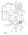
- FIG. 1 is a schematic illustration of engine assembly 10, which is an engine assembly of a motorized vehicle, such as a military transportation vehicle used in a remote environment (e.g., desert environments).
- Engine assembly 10 includes fuel tank 12, primary fuel line 14, engine 16, exhaust pipe 18, secondary fuel line 20, and dual-function system 22.
- dual-function system 22 is configured to operate as a water recovery system for collecting water and as an APU for generating electrical power.
- Fuel tank 12, primary fuel line 14, engine 16, and exhaust pipe 18 are standard engine components of a motorized vehicle. Fuel tank 12 supplies fuel to engine 16 via primary fuel line 14. Fuel tank 12 supplies fuel to engine 16 via primary fuel line 14. Engine 16 is an internal combustion engine that emits exhaust gases through exhaust pipe 18 while running. Exhaust pipe 18 discards the exhaust gases from engine 16, and includes pipe wall 24. While exhaust pipe 18 is shown and described as a pipe, the term "exhaust pipe”, as used herein, is intended to include any type of assembly that relays exhaust gases from a combustion engine.
- Pipe wall 24 is a standard exhaust pipe wall that extends from engine 16 to an exit of exhaust pipe 18. For ease of discussion, the emission control components disposed along exhaust pipe 18 (e.g., a catalytic converter and a muffler) are omitted.
- Secondary fuel line 20 is an additional fuel line that interconnects fuel tank 12 and dual-function system 22 for supplying fuel to dual-function system 22.
- Dual-function system 22 is disposed between exhaust pipe 18 and secondary fuel line 20, and includes control system 26, battery system 28, heat source 30, vent line 32, rotatable assembly 34, and heat exchanger 36.
- Control system 26 includes controller 38 and signal lines 40, 42, and 44, where controller 38 is an electronic control unit secured to the motorized vehicle. As discussed below, controller 38 allows an operator to direct the operation of heat source 30 via signal line 40, and to direct the operation of rotatable assembly 34 via signal lines 42 and 44.
- Battery system 28 includes battery 46 and electrical wires 48, where battery 46 is a rechargeable battery configured to both transmit and receive electrical power. Battery 46 is electrically connected to rotatable assembly 34 via electrical wires 48, which allows battery 46 to be remotely located from rotatable assembly 34.
- Heat source 30 is a fuel-based burner connected between secondary fuel line 20 and vent line 32. Heat source 30 bums the fuel received from secondary fuel line 20 and air to generate heat (e.g., up to 650°C). The exhaust gases from the ignited fuel exits heat source 30 through vent line 32. In an alternative embodiment, heat source 30 receives fuel from an auxiliary fuel tank, which avoids the need of connecting secondary fuel line 20 to fuel tank 12. This also allows different heat sources to be interchanged for heat source 30.
- Rotatable assembly 34 includes drive hub 50, idler hub 52, shaft 54, and Stirling engine 56.
- Drive hub 50 is a motor-powered hub secured to a first end of shaft 54, and to a frame (not shown) of the vehicle.
- Drive hub 50 rotates shaft 54 around axis 58 based on signals relayed from controller 38 via signal line 44.
- Idler hub 52 is a second hub secured to an opposing end of shaft 54 from drive hub 50, and is also secured to the frame of the vehicle.
- Shaft 54 is an axle shaft extending along axis 58, and is rotatably secured to the frame of the vehicle via drive hub 50 and idler hub 52.
- One or more of drive hub 50, idler hub 52, and shaft 54 may also include ball-bearing assemblies (not shown) to assist the rotation of shaft 54.
- Stirling engine 56 is a Stirling cycle-powered engine that includes engine body 62 and conductive head 64.
- Engine body 62 and conductive head 64 are standard Stirling engine components, which internally include a compressible gas (not shown), a power piston (not shown), and a displacer (not shown) for generating piston and displacer movement pursuant to a Stirling-cycle process.
- Suitable engines for Stirling engine 56 include engines that operate under Stirling-cycle processes, such as alpha-, beta-, and gamma-class Stirling engines. Examples of suitable commercially available Stirling engines include engines from Sunpower, Inc. Athens, OH; and Infinia Corporation, Kennewick, WA.
- Engine body 62 is secured to shaft 54 between drive hub 50 and idler hub 52. As a result of the secure connection between shaft 54 and engine body 62, the rotation of shaft 54 correspondingly rotates Stirling engine 56 around axis 58.
- Engine body 62 is also the portion of rotatable assembly 34 that receives signals from controller 38 via signal line 42, and that is electrically connected to battery 46 via electrical wires 48.
- Signal line 42 and electrical wires 48 are desirably flexible to remain connected to engine body 62 while Stirling engine 56 rotates around axis 58.
- Conductive head 64 is a heat-exchanging component that exhibits a thermal gradient during a Stirling-cycle process.
- Heat exchanger 36 is an intermediate vapor-transport heat exchanger secured around pipe wall 24 of exhaust pipe 18 at location 60.
- Location 60 may be any place along exhaust pipe 18 between engine 16 and the exit of exhaust pipe 18, and is desirably situated after a catalytic converter (not shown) of the vehicle to reduce pollutants in the exhaust gases.
- Heat exchanger 36 is configured to engage with conductive head 64 of Stirling engine 56, and transfers heat between exhaust pipe 18 and conductive head 64. While shown as a vapor-transport heat exchanger, heat exchanger 36 may alternatively be any type of conductive or convective heat-transfer system for transferring heat between exhaust pipe 18 and conductive head 64.
- Stirling engine 56 is rotatably positioned around axis 58 such that conductive head 64 engages with heat exchanger 36. In this rotational position, Stirling engine 56 is in an electrically-driven, refrigeration mode, where Stirling engine 56 is configured to receive electrical power from battery 46 for reducing the temperature of pipe wall 24 at location 60 via heat exchanger 36.
- controller 38 While Stirling engine 56 is positioned in the refrigeration mode, controller 38 directs Stirling engine 56 (via signal line 42) to draw electrical power from battery 46 through electrical wires 48. This is performed with an electrical switch or switches (not shown) located within engine body 62, which is selectable between an input state, a deactivated state, and an output state based on the signals from controller 38. As such, controller 38 directs the electrical switch(es) to change from the deactivated state to the input state, thereby allowing Stirling engine 56 to draw electrical power from battery 46. The electrical power causes the compressible gas within Stirling engine 56 to expand and contract pursuant to a Stirling-cycle process, thereby causing conductive head 64 to become cold through a refrigeration effect.
- conductive head 64 contacts heat exchanger 36, the cold temperature of conductive head 64 draws heat from heat exchanger 36, thereby reducing the temperature of heat exchanger 36.
- heat exchanger 36 draws heat from pipe wall 24 at location 60, thereby reducing the temperature of pipe wall 24 at location 60.
- the exhaust gases of internal combustion engines, such as engine 16 contain water vapor.
- the reduced temperature of pipe wall 24 causes water vapor in the exhaust gases flowing through exhaust pipe 18 to condense to liquid water on the inner surface of pipe wall 24.
- the condensed water may then be filtered and collected for use by personnel. Suitable systems and methods for filtering the collected water are disclosed in Jagtoyen et al., U.S. Patent No. 6,581,375 .
- dual-function system 22 functions as a water recovery system. This allows personnel to obtain water in remote locations and in emergency situations.
- conductive head 64 is shown in FIG. 1 as engaging with heat exchanger 36
- dual-function system 22 may be designed in a variety of manners such that conductive head 64 transfers heat from exhaust pipe 18 while Stirling engine 56 is positioned in the refrigeration mode.
- conductive head 64 may be designed to directly engage with pipe wall 24 of exhaust pipe 18 to draw heat from pipe wall 24.
- heat exchanger 36 is omitted.
- a portion of heat exchanger 36 extends within exhaust pipe 18 at location 60 to increase the heat transfer rate.
- a portion of pipe wall 24 at location 60 is removed and heat exchanger 36 is secured to pipe wall 24 such that a portion of heat exchanger 36 extends within exhaust pipe 18 at location 60.
- shaft 54 and Stirling engine 56 are rotatable around axis 58.
- controller 38 Prior to rotating shaft 54 and Stirling engine 56, controller 38 directs the electrical switch(es) within engine body 62 to change from the input state to the deactivated state. This cuts off the power supply from battery 46, which shuts down Stirling engine 56.
- controller 38 To rotate Stirling engine 56 around axis 58, controller 38 directs drive hub 50 (via signal line 44) to rotate shaft 54 around axis 58.
- the rotation of shaft 54 correspondingly rotates Stirling engine 56 around axis 58, which disengages conductive head 64 from heat exchanger 36 and exhaust pipe 18.
- Drive hub 50 rotates shaft 54 and Stirling engine 56 until conductive head 64 engages with heat source 30. In this rotational position, Stirling engine 56 is in a thermally-driven, power generation mode, and functions as an APU.
- FIG. 2 is a schematic illustration of engine assembly 10, where Stirling engine 56 is positioned in the thermally-driven, power generation state. As shown, while Stirling engine 56 is positioned in the power generation state, conductive head 64 engages with heat source 30. During operation, controller 38 directs the electrical switch(es) (not shown) located within engine body 62 to change from the deactivated state to the output state (via signal line 42). This allows Stirling engine 56 to transmit generated electrical power to battery 46 through electrical wires 48.
- Controller 38 also directs heat source 30 to receive fuel from secondary fuel line 20 and to ignite the fuel and air to generate heat in the proximity of conductive head 64 (via signal line 40).
- Conductive head 64 transfers the generated heat away from heat source 30 via convection and/or conduction, which causes the temperature of conductive head 64 to increase.
- This correspondingly causes the compressible gas within Stirling engine 56 to expand and contract pursuant to a Stirling-cycle process that is thermodynamically reversed from the refrigeration-based process discussed above.
- This causes Stirling engine 56 to generate electrical power, which is directed to battery 46 via electrical wires 48.
- Stirling engine 56 is configured to recharge battery 46 while relying on the fuel of fuel tank 12, thereby functioning as an APU. This allows personnel to obtain electrical power in remote locations for use with electronic equipment, such as surveillance, illumination, and communication equipment.
- controller 38 When an operator desires to switch Stirling engine 56 back to the refrigeration mode, controller 38 directs heat source 30 to shut off (via signal line 40), and directs the electrical switch(es) within engine body 62 to change from the output state to the deactivated state (via signal line 42). Controller 38 then directs drive hub 50 to rotate shaft 54 back around axis 58 in an opposite rotational direction from the previous rotation. This causes conductive head 64 to disengage from heat source 30 and rotate around axis 58 until conductive head 64 engages with heat exchanger 36.
- drive hub 50 is configured to rotate shaft 54 and Stirling engine 56 in the same rotational direction around axis 58 during each rotational period (i.e., shaft 54 and Stirling engine 56 rotate 360 degrees to return to the original position). This embodiment requires more space for the rotational range of Stirling engine 56, but reduces the mechanical complexity of drive hub 50.
- Rotating Stirling engine 56 between the refrigeration mode and the power generation mode allows a single Stirling engine to alternatively function as a water recovery system for collecting water and as an APU for generating power. This reduces material costs, installation costs, and space that are otherwise necessary with the use of multiple systems. While Stirling engine 56 is configured to rotate between the refrigeration mode and the power generation mode, Stirling engine 56 may alternatively be repositioned between the refrigeration mode and the power generation mode in a variety of manners based on the arrangement of engine assembly 10 (e.g., linear movement). However, rotating Stirling engine 56 between the refrigeration mode and the power generation mode provides an efficient means to operate dual-function system 22.
- dual-function system 22 is controlled in a manual manner rather than the electronic manner discussed above.
- controller 38 and signal lines 40, 42, and 44 are omitted, and an operator manually rotates shaft 54 and Stirling engine 56 around axis 58 between the refrigeration mode and the power generation mode.
- Heat source 30 is also manually ignited when Stirling engine 56 is positioned in the power generation mode.
- dual-function system 22 may alternatively be used with a variety of remotely-operated equipment that emit exhaust gases containing water vapor.
- dual-function system 22 is suitable for use with motorized machines such as industrial mining equipment and oil-rigging platforms.
- Stirling engine 56 By allowing Stirling engine 56 to be positioned between a refrigeration mode and a power generation mode, a single system (i.e., dual-function system 22) may be used with such machines to provide water and electrical power when needed.
Landscapes
- Engineering & Computer Science (AREA)
- Chemical & Material Sciences (AREA)
- Combustion & Propulsion (AREA)
- Mechanical Engineering (AREA)
- General Engineering & Computer Science (AREA)
- Transportation (AREA)
- Engine Equipment That Uses Special Cycles (AREA)
Applications Claiming Priority (1)
| Application Number | Priority Date | Filing Date | Title |
|---|---|---|---|
| US11/500,117 US7490469B2 (en) | 2006-08-07 | 2006-08-07 | Dual-function stirling engine system |
Publications (3)
| Publication Number | Publication Date |
|---|---|
| EP1892404A2 true EP1892404A2 (fr) | 2008-02-27 |
| EP1892404A3 EP1892404A3 (fr) | 2011-03-30 |
| EP1892404B1 EP1892404B1 (fr) | 2015-04-15 |
Family
ID=38846981
Family Applications (1)
| Application Number | Title | Priority Date | Filing Date |
|---|---|---|---|
| EP07253077.7A Not-in-force EP1892404B1 (fr) | 2006-08-07 | 2007-08-06 | Système de moteur Stirling double fonction |
Country Status (2)
| Country | Link |
|---|---|
| US (1) | US7490469B2 (fr) |
| EP (1) | EP1892404B1 (fr) |
Cited By (4)
| Publication number | Priority date | Publication date | Assignee | Title |
|---|---|---|---|---|
| CN103470352A (zh) * | 2013-09-23 | 2013-12-25 | 谢勇 | 基于斯特林发动机的汽车尾气余热回收装置 |
| US8844291B2 (en) | 2010-12-10 | 2014-09-30 | Vaporgenics Inc. | Universal heat engine |
| CN107650667A (zh) * | 2017-09-29 | 2018-02-02 | 温州泓呈祥科技有限公司 | 一种基于空气能的钢绳驱动汽车 |
| US11137177B1 (en) | 2019-03-16 | 2021-10-05 | Vaporgemics, Inc | Internal return pump |
Families Citing this family (3)
| Publication number | Priority date | Publication date | Assignee | Title |
|---|---|---|---|---|
| US8726661B2 (en) | 2010-08-09 | 2014-05-20 | GM Global Technology Operations LLC | Hybrid powertrain system including an internal combustion engine and a stirling engine |
| EP2490213A1 (fr) * | 2011-02-19 | 2012-08-22 | beyo GmbH | Procédé de conversion de messages de textes à caractères en fichiers audio avec leurs titres respectifs pour la sélection et la lecture à haute voix avec des dispositifs mobiles |
| DE102013009219A1 (de) * | 2013-05-31 | 2014-12-04 | Man Truck & Bus Ag | Verfahren und Vorrichtung zum Betreiben einer Brennkraftmaschine |
Citations (1)
| Publication number | Priority date | Publication date | Assignee | Title |
|---|---|---|---|---|
| US20020017098A1 (en) | 2000-06-14 | 2002-02-14 | Lennart Johansson | Exhaust gas alternator system |
Family Cites Families (9)
| Publication number | Priority date | Publication date | Assignee | Title |
|---|---|---|---|---|
| US4070860A (en) * | 1976-12-30 | 1978-01-31 | The United States Of America As Represented By The Secretary Of The Army | Automotive accessory engine |
| US4702903A (en) * | 1983-10-03 | 1987-10-27 | Keefer Bowie | Method and apparatus for gas separation and synthesis |
| US6216444B1 (en) * | 1998-05-14 | 2001-04-17 | Edmund Ferdinand Nagel | Combustion engine |
| US6672063B1 (en) * | 2002-09-25 | 2004-01-06 | Richard Alan Proeschel | Reciprocating hot air bottom cycle engine |
| WO2004067933A2 (fr) * | 2003-01-21 | 2004-08-12 | Los Angeles Advisory Services Inc. | Source d'energie a faible emission |
| US6871495B2 (en) | 2003-05-08 | 2005-03-29 | The Boeing Company | Thermal cycle engine boost bridge power interface |
| JP4248303B2 (ja) * | 2003-05-09 | 2009-04-02 | 本田技研工業株式会社 | 燃焼機関およびスターリング機関を備える動力装置 |
| CN100404837C (zh) | 2003-09-25 | 2008-07-23 | 珍巴多工业股份有限公司 | 斯特林循环发动机 |
| JP3788453B2 (ja) | 2003-10-01 | 2006-06-21 | トヨタ自動車株式会社 | 排熱回収装置 |
-
2006
- 2006-08-07 US US11/500,117 patent/US7490469B2/en not_active Expired - Fee Related
-
2007
- 2007-08-06 EP EP07253077.7A patent/EP1892404B1/fr not_active Not-in-force
Patent Citations (1)
| Publication number | Priority date | Publication date | Assignee | Title |
|---|---|---|---|---|
| US20020017098A1 (en) | 2000-06-14 | 2002-02-14 | Lennart Johansson | Exhaust gas alternator system |
Cited By (5)
| Publication number | Priority date | Publication date | Assignee | Title |
|---|---|---|---|---|
| US8844291B2 (en) | 2010-12-10 | 2014-09-30 | Vaporgenics Inc. | Universal heat engine |
| CN103470352A (zh) * | 2013-09-23 | 2013-12-25 | 谢勇 | 基于斯特林发动机的汽车尾气余热回收装置 |
| CN103470352B (zh) * | 2013-09-23 | 2017-03-08 | 陆安琪 | 基于斯特林发动机的汽车尾气余热回收装置 |
| CN107650667A (zh) * | 2017-09-29 | 2018-02-02 | 温州泓呈祥科技有限公司 | 一种基于空气能的钢绳驱动汽车 |
| US11137177B1 (en) | 2019-03-16 | 2021-10-05 | Vaporgemics, Inc | Internal return pump |
Also Published As
| Publication number | Publication date |
|---|---|
| EP1892404B1 (fr) | 2015-04-15 |
| EP1892404A3 (fr) | 2011-03-30 |
| US7490469B2 (en) | 2009-02-17 |
| US20090007562A1 (en) | 2009-01-08 |
Similar Documents
| Publication | Publication Date | Title |
|---|---|---|
| EP1892404B1 (fr) | Système de moteur Stirling double fonction | |
| JP4248303B2 (ja) | 燃焼機関およびスターリング機関を備える動力装置 | |
| EP1916397B1 (fr) | Appareil de moteur doté d'un système de récupération de chaleur et procédé de récupération de chaleur correspondant | |
| US7730723B2 (en) | Exhaust heat recovery apparatus | |
| EP3211195B1 (fr) | Procédé intégré d'entraînement d'un compresseur à co2 d'un système de capture de co2 au moyen d'une turbine d'échappement d'un moteur à combustion interne à bord d'une source mobile | |
| EP1574698B1 (fr) | Système de récupération de chaleur des gaz d'échappement d'un véhicule | |
| CN101410577B (zh) | 汽车供能系统 | |
| US7895835B2 (en) | Exhaust heat recovery apparatus | |
| US20140190162A1 (en) | Heat Recovery System for a Gas Turbine Engine | |
| EP3992447B1 (fr) | Moteur d'aéronef comportant un moteur thermique à co2 supercritique | |
| EP1736650A2 (fr) | Procédé et dispositif d'utilisation pour turbines à gaz | |
| WO2016067303A2 (fr) | Système de récupération de chaleur pour la famille des turbines à gaz entraînées par arbre pour l'aéronautique | |
| WO2007109414A2 (fr) | Système de récupération d'énergie | |
| WO2006075571A8 (fr) | Systeme de recuperation de la chaleur dissipee et unite de conversion thermoelectrique | |
| RU2247850C2 (ru) | Компактный электроэнергетический агрегат и метод вырабатывания энергии | |
| WO2012057848A1 (fr) | Système de récupération de chaleur pour moteur de turbine à gaz | |
| US20150000274A1 (en) | Waste heat recovery system including connection to a vehicle air conditioning system | |
| US8776516B2 (en) | Exhaust heat recovery system | |
| US20240359812A1 (en) | Multiple heat source cryogenic bottoming cycle sequencing and routing | |
| KR101966466B1 (ko) | 터빈 제너레이팅 장치 및 이를 구비하는 내연기관의 배기열 재활용 시스템 | |
| FR2810076A1 (fr) | Appareil modulaire pour la generation d'energie | |
| US12228095B2 (en) | Waste heat recovery system as a backup system for a machine for the production of energy | |
| EP4678894A2 (fr) | Séquençage et routage de cycle de fond cryogénique à sources de chaleur multiples | |
| AU2007278810A1 (en) | Energy supply system | |
| US8863520B2 (en) | Method and apparatus for an external combustion engine having a steam generator |
Legal Events
| Date | Code | Title | Description |
|---|---|---|---|
| PUAI | Public reference made under article 153(3) epc to a published international application that has entered the european phase |
Free format text: ORIGINAL CODE: 0009012 |
|
| AK | Designated contracting states |
Kind code of ref document: A2 Designated state(s): AT BE BG CH CY CZ DE DK EE ES FI FR GB GR HU IE IS IT LI LT LU LV MC MT NL PL PT RO SE SI SK TR |
|
| AX | Request for extension of the european patent |
Extension state: AL BA HR MK YU |
|
| PUAL | Search report despatched |
Free format text: ORIGINAL CODE: 0009013 |
|
| AK | Designated contracting states |
Kind code of ref document: A3 Designated state(s): AT BE BG CH CY CZ DE DK EE ES FI FR GB GR HU IE IS IT LI LT LU LV MC MT NL PL PT RO SE SI SK TR |
|
| AX | Request for extension of the european patent |
Extension state: AL BA HR MK RS |
|
| RIC1 | Information provided on ipc code assigned before grant |
Ipc: B60K 8/00 20060101ALI20110221BHEP Ipc: F02G 1/043 20060101AFI20080121BHEP Ipc: F01N 5/02 20060101ALI20110221BHEP Ipc: F01N 3/02 20060101ALI20110221BHEP Ipc: F02G 5/02 20060101ALI20110221BHEP |
|
| 17P | Request for examination filed |
Effective date: 20110927 |
|
| AKX | Designation fees paid |
Designated state(s): DE FR GB |
|
| GRAP | Despatch of communication of intention to grant a patent |
Free format text: ORIGINAL CODE: EPIDOSNIGR1 |
|
| INTG | Intention to grant announced |
Effective date: 20150113 |
|
| GRAS | Grant fee paid |
Free format text: ORIGINAL CODE: EPIDOSNIGR3 |
|
| RAP1 | Party data changed (applicant data changed or rights of an application transferred) |
Owner name: AEROJET ROCKETDYNE, INC. |
|
| GRAA | (expected) grant |
Free format text: ORIGINAL CODE: 0009210 |
|
| AK | Designated contracting states |
Kind code of ref document: B1 Designated state(s): DE FR GB |
|
| REG | Reference to a national code |
Ref country code: GB Ref legal event code: FG4D |
|
| REG | Reference to a national code |
Ref country code: DE Ref legal event code: R096 Ref document number: 602007041043 Country of ref document: DE Effective date: 20150528 |
|
| REG | Reference to a national code |
Ref country code: FR Ref legal event code: PLFP Year of fee payment: 9 |
|
| PGFP | Annual fee paid to national office [announced via postgrant information from national office to epo] |
Ref country code: DE Payment date: 20150824 Year of fee payment: 9 Ref country code: GB Payment date: 20150818 Year of fee payment: 9 |
|
| PGFP | Annual fee paid to national office [announced via postgrant information from national office to epo] |
Ref country code: FR Payment date: 20150831 Year of fee payment: 9 |
|
| REG | Reference to a national code |
Ref country code: DE Ref legal event code: R097 Ref document number: 602007041043 Country of ref document: DE |
|
| PLBE | No opposition filed within time limit |
Free format text: ORIGINAL CODE: 0009261 |
|
| STAA | Information on the status of an ep patent application or granted ep patent |
Free format text: STATUS: NO OPPOSITION FILED WITHIN TIME LIMIT |
|
| 26N | No opposition filed |
Effective date: 20160118 |
|
| REG | Reference to a national code |
Ref country code: DE Ref legal event code: R119 Ref document number: 602007041043 Country of ref document: DE |
|
| GBPC | Gb: european patent ceased through non-payment of renewal fee |
Effective date: 20160806 |
|
| REG | Reference to a national code |
Ref country code: FR Ref legal event code: ST Effective date: 20170428 |
|
| PG25 | Lapsed in a contracting state [announced via postgrant information from national office to epo] |
Ref country code: GB Free format text: LAPSE BECAUSE OF NON-PAYMENT OF DUE FEES Effective date: 20160806 Ref country code: DE Free format text: LAPSE BECAUSE OF NON-PAYMENT OF DUE FEES Effective date: 20170301 Ref country code: FR Free format text: LAPSE BECAUSE OF NON-PAYMENT OF DUE FEES Effective date: 20160831 |