EP1892401B1 - Control method for the injection of fuel for an internal combustion engine with indirect injection and spark ignition - Google Patents
Control method for the injection of fuel for an internal combustion engine with indirect injection and spark ignition Download PDFInfo
- Publication number
- EP1892401B1 EP1892401B1 EP07301262A EP07301262A EP1892401B1 EP 1892401 B1 EP1892401 B1 EP 1892401B1 EP 07301262 A EP07301262 A EP 07301262A EP 07301262 A EP07301262 A EP 07301262A EP 1892401 B1 EP1892401 B1 EP 1892401B1
- Authority
- EP
- European Patent Office
- Prior art keywords
- injection
- fuel
- cylinder
- engine
- injector
- Prior art date
- Legal status (The legal status is an assumption and is not a legal conclusion. Google has not performed a legal analysis and makes no representation as to the accuracy of the status listed.)
- Not-in-force
Links
- 238000002347 injection Methods 0.000 title claims abstract description 91
- 239000007924 injection Substances 0.000 title claims abstract description 91
- 239000000446 fuel Substances 0.000 title claims abstract description 25
- 238000000034 method Methods 0.000 title claims abstract description 8
- 238000002485 combustion reaction Methods 0.000 title claims description 11
- 238000011144 upstream manufacturing Methods 0.000 claims description 6
- 239000007788 liquid Substances 0.000 claims description 5
- 230000003111 delayed effect Effects 0.000 claims 1
- 230000003247 decreasing effect Effects 0.000 abstract description 2
- 229930195733 hydrocarbon Natural products 0.000 description 11
- 150000002430 hydrocarbons Chemical class 0.000 description 11
- 239000012530 fluid Substances 0.000 description 7
- 239000003054 catalyst Substances 0.000 description 6
- 238000011217 control strategy Methods 0.000 description 5
- 230000010363 phase shift Effects 0.000 description 3
- 239000004215 Carbon black (E152) Substances 0.000 description 2
- 230000032683 aging Effects 0.000 description 2
- 238000001704 evaporation Methods 0.000 description 2
- 230000004048 modification Effects 0.000 description 2
- 238000012986 modification Methods 0.000 description 2
- 230000002035 prolonged effect Effects 0.000 description 2
- 235000008429 bread Nutrition 0.000 description 1
- 230000003197 catalytic effect Effects 0.000 description 1
- 238000003776 cleavage reaction Methods 0.000 description 1
- 230000000694 effects Effects 0.000 description 1
- 230000008020 evaporation Effects 0.000 description 1
- 239000002245 particle Substances 0.000 description 1
- 230000007017 scission Effects 0.000 description 1
- 239000007921 spray Substances 0.000 description 1
Images


Classifications
-
- F—MECHANICAL ENGINEERING; LIGHTING; HEATING; WEAPONS; BLASTING
- F02—COMBUSTION ENGINES; HOT-GAS OR COMBUSTION-PRODUCT ENGINE PLANTS
- F02D—CONTROLLING COMBUSTION ENGINES
- F02D41/00—Electrical control of supply of combustible mixture or its constituents
- F02D41/02—Circuit arrangements for generating control signals
- F02D41/04—Introducing corrections for particular operating conditions
- F02D41/042—Introducing corrections for particular operating conditions for stopping the engine
-
- F—MECHANICAL ENGINEERING; LIGHTING; HEATING; WEAPONS; BLASTING
- F02—COMBUSTION ENGINES; HOT-GAS OR COMBUSTION-PRODUCT ENGINE PLANTS
- F02D—CONTROLLING COMBUSTION ENGINES
- F02D41/00—Electrical control of supply of combustible mixture or its constituents
- F02D41/02—Circuit arrangements for generating control signals
- F02D41/04—Introducing corrections for particular operating conditions
- F02D41/047—Taking into account fuel evaporation or wall wetting
-
- F—MECHANICAL ENGINEERING; LIGHTING; HEATING; WEAPONS; BLASTING
- F02—COMBUSTION ENGINES; HOT-GAS OR COMBUSTION-PRODUCT ENGINE PLANTS
- F02D—CONTROLLING COMBUSTION ENGINES
- F02D41/00—Electrical control of supply of combustible mixture or its constituents
- F02D41/30—Controlling fuel injection
- F02D41/32—Controlling fuel injection of the low pressure type
- F02D41/34—Controlling fuel injection of the low pressure type with means for controlling injection timing or duration
-
- Y—GENERAL TAGGING OF NEW TECHNOLOGICAL DEVELOPMENTS; GENERAL TAGGING OF CROSS-SECTIONAL TECHNOLOGIES SPANNING OVER SEVERAL SECTIONS OF THE IPC; TECHNICAL SUBJECTS COVERED BY FORMER USPC CROSS-REFERENCE ART COLLECTIONS [XRACs] AND DIGESTS
- Y02—TECHNOLOGIES OR APPLICATIONS FOR MITIGATION OR ADAPTATION AGAINST CLIMATE CHANGE
- Y02T—CLIMATE CHANGE MITIGATION TECHNOLOGIES RELATED TO TRANSPORTATION
- Y02T10/00—Road transport of goods or passengers
- Y02T10/10—Internal combustion engine [ICE] based vehicles
- Y02T10/40—Engine management systems
Definitions
- the present invention relates to a fuel injection control method for an internal combustion engine with indirect injection and controlled ignition.
- Tests for measuring the concentration of unburned hydrocarbons using a rapid concentration analyzer of the FFID (Flame Ionization Detector) type at the outlet of the exhaust valves made it possible to quantify the mass of liquid film present before the injection cut.
- FFID Flume Ionization Detector
- the fuel injection control method for indirect combustion internal combustion engine and controlled ignition comprising at least one cylinder, an injector associated with the intake duct of the cylinder and controlled during the cycle.
- fuel such as gasoline
- the fuel injection control method for indirect combustion internal combustion engine and controlled ignition comprising at least one cylinder, an injector associated with the intake duct of the cylinder and controlled during the cycle.
- the injector consists in controlling the injector by shifting the fuel injection phase in the intake duct beyond from the instant of closing of the intake valve before the injection is cut off and simultaneously reducing the fuel injection time during this prolonged injection phase until the injection is cut off, in order to reduce the quantity of injection fluid film of fuel present on the walls of the intake duct.
- the period of shift of the injection phase to the cutoff of the injector can be parameterized in number of operating cycles of the engine.
- the invention also provides an internal combustion engine with indirect injection and controlled ignition comprising a plurality of cylinders, intake ducts each associated with a cylinder with which the intake ducts communicate via an intake valve of the cylinder.
- cylinder injectors each associated with an intake duct and controlled during the operating cycle of the engine so as to inject fuel, such as gasoline, into the intake ducts upstream of the intake valves, and which is characterized in that each of the injectors is controlled according to the method as defined above.
- the strategy of the invention making it possible to reduce the amount of HC unburned hydrocarbons at the beginning of cleavage of the invention is achieved by two simultaneous actions comprising an action on the injection timing and an action on the injection time.
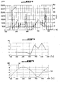
- the strategy adopted concerning the action on the injection timing with respect to the angular position of the crankshaft consists in performing an injection phasing switchover from an open intake valve injection phasing as indicated in FIG. PAO at injection timing with closed intake valve as indicated in PAF prior to injection cut-off.
- the injector 1 is controlled to shift the fuel injection phasing in the intake duct 3 beyond the closing time of the intake valve 4 before cutting off the injection.
- Such a changeover creates an enrichment E of the engine as indicated in figure 6 if you keep the same fuel injection time.
- the second strategy action consists in decreasing simultaneously with the first action, the injection time as represented in FIG. figure 7 before the cut C of the injection.
- Figures 7 and 8 considered together show that the injector 1 is driven by the electronic control computer of the engine during an injection time of 4000 microseconds during the PAO phasing injection 4 admission valve open and, during the injection PAF phasing With the inlet valve closed, the injection time at the time of this phase shift is lowered as indicated in Ab before the injection cutoff C occurring with the inlet valve closed.
- the control strategy of the injector according to the invention makes it possible not only to reduce the emissions of unburned hydrocarbons HC, but also the exotherm of the catalyst generally found in the prior art and, consequently, to slow the aging of the this one.
- control strategy of the invention requires no modification of the engine and / or its components, but only a modification of the software the electronic engine control computer. Thus, this strategy operates at low cost.
Landscapes
- Engineering & Computer Science (AREA)
- Chemical & Material Sciences (AREA)
- Combustion & Propulsion (AREA)
- Mechanical Engineering (AREA)
- General Engineering & Computer Science (AREA)
- Electrical Control Of Air Or Fuel Supplied To Internal-Combustion Engine (AREA)
- Fuel-Injection Apparatus (AREA)
- Combustion Methods Of Internal-Combustion Engines (AREA)
Abstract
Description
La présente invention concerne un procédé de commande d'injection de carburant pour moteur à combustion interne à injection indirecte et allumage commandé.The present invention relates to a fuel injection control method for an internal combustion engine with indirect injection and controlled ignition.
Elle s'adresse en particulier à des moteurs à essence comprenant un dispositif d'injection indirecte multipoint.It is particularly intended for gasoline engines comprising an indirect multipoint injection device.
Un dispositif d'injection indirecte d'essence est représenté en
En injection indirecte, une partie de l'essence injectée projetée sur les parois du conduit d'admission 3 comme indiqué en A se dépose sur ces parois sous forme d'un film liquide d'essence comme schématisé en B.In indirect injection, a part of the injected gasoline projected on the walls of the
En début de coupure de l'injection d'essence, le film liquide présent sur le conduit d'admission s'évaporant comme indiqué en C, il pénètre dans la chambre de combustion et ne brûle pas. Il se crée alors un pic d'hydrocarbures imbrûlés HC en sortie du moteur et en amont du catalyseur comme représenté en
Pour réduire le pic d'hydrocarbures imbrûlés lors de la coupure d'injection d'essence, il est nécessaire de diminuer la quantité d'essence présente sur les parois du conduit d'admission avant cette coupure.To reduce the peak of unburned hydrocarbons during the fuel injection cut, it is necessary to reduce the amount of gasoline present on the walls of the intake duct before this cut.
A cet effet, deux possibilités existent:
- optimiser l'injecteur en choisissant un angle d'inclinaison de celui-ci relativement au conduit d'admission comme représenté en
figure 1 , ou en utilisant un injecteur à pulvérisation améliorée; - optimiser le contrôle du moteur par un calculateur électronique suivant une stratégie de commande de l'injection d'essence avant la coupure de cette injection.
- optimize the injector by choosing an angle of inclination thereof relative to the intake duct as shown in FIG.
figure 1 , or using an improved spray injector; - optimize the control of the engine by an electronic computer according to a control strategy of the injection of gasoline before the cutting of this injection.
L'invention s'inscrit dans cette seconde possibilité par laquelle une stratégie de commande de l'injection a été identifiée, comme on le verra ultérieurement, pour diminuer la quantité d'essence présente sur les parois du conduit d'admission avant la coupure de l'injection et de l'allumage.The invention is part of this second possibility by which an injection control strategy has been identified, as will be seen later, to reduce the amount of gasoline present on the walls of the intake duct before cutting. injection and ignition.
Cette stratégie a été élaborée à partir des constatations suivantes.This strategy was developed from the following findings.
Des essais de mesure de concentration d'hydrocarbures imbrûlés à l'aide d'un analyseur rapide de concentration du type FFID (Détecteur à Ionisation de Flamme) en sortie des soupapes d'échappement ont permis de quantifier la masse de film liquide présent avant la coupure d'injection.Tests for measuring the concentration of unburned hydrocarbons using a rapid concentration analyzer of the FFID (Flame Ionization Detector) type at the outlet of the exhaust valves made it possible to quantify the mass of liquid film present before the injection cut.
Il apparaît que le phasage de l'injection d'essence a un impact important sur la masse du film liquide ou fluide avant la coupure d'injection comme cela ressort des
Il apparaît donc des
La présente invention a pour but de proposer une nouvelle stratégie permettant d'optimiser davantage la coupure d'injection d'essence afin de diminuer la quantité d'hydrocarbures imbrûlés en début de la coupure d'injection.The object of the present invention is to propose a new strategy making it possible to further optimize the gasoline injection cut in order to reduce the quantity of unburned hydrocarbons at the beginning of the injection cutoff.
A cet effet, selon l'invention, le procédé de commande d'injection du carburant pour moteur à combustion interne à injection indirecte et allumage commandé comprenant au moins un cylindre, un injecteur associé au conduit d'admission du cylindre et piloté lors du cycle de fonctionnement du moteur de manière à injecter du carburant, tel que de l'essence, dans le conduit d'admission en amont de la soupape d'admission ouverte du cylindre avant de pénétrer dans la chambre de combustion du cylindre, est caractérisé en ce qu'il consiste à piloter l'injecteur en décalant le phasage d'injection de carburant dans le conduit d'admission au-delà de l'instant de fermeture de la soupape d'admission avant coupure de l'injection et simultanément diminuer le temps d'injection de carburant pendant ce phasage prolongé d'injection jusqu'à la coupure de l'injection, afin de diminuer la quantité de film fluide de carburant présent sur les parois du conduit d'admission.For this purpose, according to the invention, the fuel injection control method for indirect combustion internal combustion engine and controlled ignition comprising at least one cylinder, an injector associated with the intake duct of the cylinder and controlled during the cycle. of operating the engine so as to inject fuel, such as gasoline, into the intake duct upstream of the open cylinder inlet valve before entering the combustion chamber of the cylinder, is characterized in that it consists in controlling the injector by shifting the fuel injection phase in the intake duct beyond from the instant of closing of the intake valve before the injection is cut off and simultaneously reducing the fuel injection time during this prolonged injection phase until the injection is cut off, in order to reduce the quantity of injection fluid film of fuel present on the walls of the intake duct.
La période de décalage du phasage d'injection jusqu'à la coupure de l'injecteur est paramétrable en nombre de cycles de fonctionnement du moteur.The period of shift of the injection phase to the cutoff of the injector can be parameterized in number of operating cycles of the engine.
L'invention vise également un moteur à combustion interne à injection indirecte et allumage commandé comprenant plusieurs cylindres, des conduits d'admission associés chacun à un cylindre avec lequel les conduits d'admission communiquent par l'intermédiaire d'une soupape d'admission du cylindre, des injecteurs associés chacun à un conduit d'admission et pilotés lors du cycle de fonctionnement du moteur de manière à injecter du carburant, tel que de l'essence, dans les conduits d'admission en amont des soupapes d'admission, et qui est caractérisé en ce que chacun des injecteurs est piloté suivant le procédé tel que défini précédemment.The invention also provides an internal combustion engine with indirect injection and controlled ignition comprising a plurality of cylinders, intake ducts each associated with a cylinder with which the intake ducts communicate via an intake valve of the cylinder. cylinder, injectors each associated with an intake duct and controlled during the operating cycle of the engine so as to inject fuel, such as gasoline, into the intake ducts upstream of the intake valves, and which is characterized in that each of the injectors is controlled according to the method as defined above.
L'invention sera mieux comprise, et d'autres buts, caractéristiques, détails et avantages de celle-ci apparaîtront plus clairement dans la description explicative qui va suivre faite en référence aux dessins schématiques annexés donnés uniquement à titre d'exemple illustrant un mode de réalisation de l'invention et dans lesquels:
- la
figure 1 est une vue en coupe longitudinale d'un conduit d'admission comportant un injecteur de carburant d'un dispositif d'injection indirecte pour moteur à injection indirecte et allumage commandé; - la
figure 2 est un graphe représentant les pics d'hydrocarbures imbrûlés exprimés en particules par millions (ppm) lors de la coupure d'injection d'essence sur un extrait de cycle d'essai normalisé; - la
figure 3 représente l'évolution de la masse du film fluide présent sur la paroi d'un conduit d'admission en fonction de l'angle de rotation du vilebrequin du moteur; - la
figure 4 représente les levées des soupapes d'échappement et d'admission en fonction de l'angle de rotation du vilebrequin; - la
figure 5 représente la variation de phasage d'injection conforme à l'invention en fonction du temps de fonctionnement du moteur proportionnel au nombre de cycles de ce moteur; - la
figure 6 est un gaphe représentant l'enrichissement du moteur en fonction du temps de fonctionnement de celui-ci lors de la variation de phasage d'injection de lafigure 5 ; - la
figure 7 est un graphe représentant le temps d'injection en microsecondes en fonction du temps de fonctionnement du moteur suivant la stratégie de commande d'injecteur conforme à l'invention; et - la
figure 8 représente l'évolution du phasage d'injection en fonction du temps de fonctionnement du moteur et conformément à la stratégie d'injection avant coupure d'injection de lafigure 7 .
- the
figure 1 is a longitudinal sectional view of an intake duct comprising a fuel injector of an indirect injection device for indirect injection engine and controlled ignition; - the
figure 2 is a graph of the unburned hydrocarbon peaks expressed as a million (ppm) particles at the fuel injection cutoff on a standardized test cycle extract; - the
figure 3 represents the evolution of the mass of the fluid film present on the wall of an intake duct as a function of the rotation angle of the crankshaft of the engine; - the
figure 4 represents the lift of the exhaust and intake valves as a function of the rotation angle of the crankshaft; - the
figure 5 represents the variation of injection phasing according to the invention as a function of the operating time of the motor proportional to the number of cycles of this engine; - the
figure 6 is a gaphe representing the enrichment of the engine as a function of the operating time of the latter during the injection phase shift of thefigure 5 ; - the
figure 7 is a graph representing the injection time in microseconds as a function of the operating time of the engine according to the injector control strategy according to the invention; and - the
figure 8 represents the evolution of the injection timing as a function of the operating time of the engine and in accordance with the strategy of injection before injection cutoff of thefigure 7 .
La stratégie de l'invention permettant de diminuer la quantité d'hydrocarbures imbrûlés HC en début de coupure de l'invention est réalisée par deux actions simultanées comprenant une action sur le phasage d'injection et une action sur le temps d'injection.The strategy of the invention making it possible to reduce the amount of HC unburned hydrocarbons at the beginning of cleavage of the invention is achieved by two simultaneous actions comprising an action on the injection timing and an action on the injection time.
Comme représenté aux
La stratégie de commande de l'injecteur conforme à l'invention permet de diminuer non seulement les émissions d'hydrocarbures imbrûlés HC, mais également l'exotherme du catalyseur constaté généralement dans l'art antérieur et, par conséquent, de ralentir le vieillissement de celui-ci.The control strategy of the injector according to the invention makes it possible not only to reduce the emissions of unburned hydrocarbons HC, but also the exotherm of the catalyst generally found in the prior art and, consequently, to slow the aging of the this one.
La stratégie de commande de l'invention ne nécessite aucune modification du moteur et/ou de ses composants, mais uniquement une modification du logiciel du calculateur électronique de commande du moteur. Ainsi, cette stratégie s'opère à faible coût.The control strategy of the invention requires no modification of the engine and / or its components, but only a modification of the software the electronic engine control computer. Thus, this strategy operates at low cost.
Claims (3)
- Method for controlling fuel injection for an internal combustion engine with indirect injection and controlled ignition including at least one cylinder (2), an injector (1), that is associated with the inlet duct (3) of cylinder (2) and actuated during the engine operating cycle so as to inject fuel, such as petrol, into the inlet duct (3) upstream of the open inlet valve (4) of the cylinder (2) before it enters the combustion chamber of the cylinder (2), characterized in that it consists of controlling the injector (1) so as to delay the phase for injecting fuel into the inlet duct (3) beyond the time when the inlet valve (4) closes before the injector (1) is cut off, and simultaneously reducing the fuel injection time during this delayed injection phase until the injection (1) is cut off, in order to reduce the quantity of liquid fuel film present on the walls of the inlet duct (3).
- Method as recited in claim 1, characterized in that the delay period of the injection phase until the injection (1) is cut off is adjustable according to the number of operating cycles of the engine.
- Internal combustion engine with indirect injection and controlled ignition including multiple cylinders (2), inlet ducts (3), each of which is assigned to a cylinder (2), with which the ducts are connected via an inlet valve (4) of cylinder (2) and injectors (1), each of which is assigned to an inlet duct (3) and actuated during the operating cycle of the engine so as to inject fuel, such as petrol, into the inlet ducts (3) upstream of the inlet valves (4), characterized in that each of the injectors (1) is controlled according to the method as recited in claim 1 or 2.
Applications Claiming Priority (1)
| Application Number | Priority Date | Filing Date | Title |
|---|---|---|---|
| FR0653391A FR2904983B1 (en) | 2006-08-17 | 2006-08-17 | FUEL INJECTION CONTROL METHOD FOR INTERNAL COMBUSTION ENGINE WITH INDIRECT INJECTION AND COMMAND IGNITION |
Publications (2)
| Publication Number | Publication Date |
|---|---|
| EP1892401A1 EP1892401A1 (en) | 2008-02-27 |
| EP1892401B1 true EP1892401B1 (en) | 2010-01-20 |
Family
ID=37963727
Family Applications (1)
| Application Number | Title | Priority Date | Filing Date |
|---|---|---|---|
| EP07301262A Not-in-force EP1892401B1 (en) | 2006-08-17 | 2007-07-23 | Control method for the injection of fuel for an internal combustion engine with indirect injection and spark ignition |
Country Status (4)
| Country | Link |
|---|---|
| EP (1) | EP1892401B1 (en) |
| AT (1) | ATE455945T1 (en) |
| DE (1) | DE602007004386D1 (en) |
| FR (1) | FR2904983B1 (en) |
Family Cites Families (3)
| Publication number | Priority date | Publication date | Assignee | Title |
|---|---|---|---|---|
| JP3325392B2 (en) * | 1994-07-06 | 2002-09-17 | 本田技研工業株式会社 | Fuel injection control device for internal combustion engine |
| JP2003254118A (en) * | 2002-02-28 | 2003-09-10 | Toyota Motor Corp | Operation stop control method for vehicle internal combustion engine |
| DE10324032A1 (en) * | 2003-05-27 | 2004-12-16 | Daimlerchrysler Ag | Low-emission operation of a petrol combustion engine during turning-off, whereby the inlet and fuel injection valves are deactivated before the engine comes to a standstill and the ignition system control unit is turned-off |
-
2006
- 2006-08-17 FR FR0653391A patent/FR2904983B1/en not_active Expired - Fee Related
-
2007
- 2007-07-23 DE DE602007004386T patent/DE602007004386D1/en active Active
- 2007-07-23 AT AT07301262T patent/ATE455945T1/en not_active IP Right Cessation
- 2007-07-23 EP EP07301262A patent/EP1892401B1/en not_active Not-in-force
Also Published As
| Publication number | Publication date |
|---|---|
| DE602007004386D1 (en) | 2010-03-11 |
| FR2904983B1 (en) | 2008-11-14 |
| ATE455945T1 (en) | 2010-02-15 |
| EP1892401A1 (en) | 2008-02-27 |
| FR2904983A1 (en) | 2008-02-22 |
Similar Documents
| Publication | Publication Date | Title |
|---|---|---|
| EP1726805B1 (en) | Method to control the exhaust gas scavenging of an engine with indirect injection, in particular supercharged engine, and engine using such a method | |
| WO2013190198A1 (en) | Engine unit with a recirculation line | |
| FR2918704A3 (en) | VALVE LIFTING METHOD FOR PREPARING AN AIR-FUEL MIXTURE WHEN COLD STARTING AN INTERNAL COMBUSTION ENGINE | |
| EP1892401B1 (en) | Control method for the injection of fuel for an internal combustion engine with indirect injection and spark ignition | |
| EP0961880B1 (en) | Method and device for regenerating a fuel vapour filter for a direct injection engine | |
| FR2891308A1 (en) | METHOD FOR MANAGING A CONTROLLED AUTO-IGNITION COMBUSTION ENGINE | |
| WO2006067338A1 (en) | Method for controlling an especially petrol, spark ignition, supercharged internal combustion engine | |
| EP3673165B1 (en) | Method for operating a combustion engine according to the thermodynamic conditions in the intake and exhaust lines | |
| WO2006117486A1 (en) | Method for reducing hydrocarbon emissions from a cold engine and device and engine for carrying out said method | |
| FR2830569A1 (en) | METHOD FOR HEATING A CATALYST LOCATED IN THE EXHAUST DEVICE OF AN INTERNAL COMBUSTION ENGINE | |
| FR2804475A1 (en) | DEVICE FOR INJECTING NATURAL GAS INTO THE COMBUSTION CHAMBER OF A CYLINDER | |
| FR2953887A1 (en) | Exhaust gas temperature determining method for petrol internal combustion engine of automobile, involves determining temperature rise of exhaust gas due to heat input by combustion reaction between excess air mass and unburnt fuel mass | |
| EP1769148B1 (en) | Improved method for controlling an internal combustion engine with the aim of reducing the pollutant emissions, engine operating according to this method, and motor vehicle equipped with said engine | |
| FR2870887A1 (en) | METHOD FOR MANAGING AN INTERNAL COMBUSTION ENGINE | |
| EP1870568B1 (en) | Internal combustion engine with indirect injection, in particular a supercharged engine with controlled ignition with two intakes to provide a phase of scavenging burned gases | |
| EP2562400A1 (en) | Method for regenerating a particulate filter of an internal combustion engine | |
| FR3156833A1 (en) | Method for controlling a stratified combustion internal combustion engine for knock noise reduction and corresponding powertrain | |
| FR3051227A1 (en) | METHOD FOR CONTROLLING A CONTROL IGNITION ENGINE | |
| EP2044312A2 (en) | Method for reducing hydrocarbon emissions from a cold engine with external fuel injection and engine for the implementation of said method | |
| FR3072129A1 (en) | METHOD FOR MANAGING THE OPERATION OF A DIRECT INJECTION DIRECT INJECTION IGNITION ENGINE | |
| FR2904051A1 (en) | METHOD FOR REGENERATING A PARTICLE FILTER | |
| FR2902461A1 (en) | Super-charged spark injection internal combustion engine for heavy vehicle, has petrol pump providing total quantity of petrol to injector under specific pressure to inject petrol into duct in time interval consecutive to closing of valve | |
| EP1703105A1 (en) | System for assisting the regeneration of a storage/releasing NOX trap in an exhaust system of a motor vehicle | |
| FR2921692A1 (en) | Air-fuel e.g. natural gaseous fuel, mixture combustion controlling method for e.g. four-stroke engine of vehicle, involves obtaining combustion of air-fuel mixture by self-ignition resulting from combustion of another air-fuel mixture | |
| FR2882100A1 (en) | FUEL INJECTION CONTROL METHOD FOR INTERNAL COMBUSTION ENGINE AND ENGINE USING SUCH A METHOD |
Legal Events
| Date | Code | Title | Description |
|---|---|---|---|
| PUAI | Public reference made under article 153(3) epc to a published international application that has entered the european phase |
Free format text: ORIGINAL CODE: 0009012 |
|
| AK | Designated contracting states |
Kind code of ref document: A1 Designated state(s): AT BE BG CH CY CZ DE DK EE ES FI FR GB GR HU IE IS IT LI LT LU LV MC MT NL PL PT RO SE SI SK TR |
|
| AX | Request for extension of the european patent |
Extension state: AL BA HR MK YU |
|
| 17P | Request for examination filed |
Effective date: 20080723 |
|
| AKX | Designation fees paid |
Designated state(s): AT BE BG CH CY CZ DE DK EE ES FI FR GB GR HU IE IS IT LI LT LU LV MC MT NL PL PT RO SE SI SK TR |
|
| GRAP | Despatch of communication of intention to grant a patent |
Free format text: ORIGINAL CODE: EPIDOSNIGR1 |
|
| GRAS | Grant fee paid |
Free format text: ORIGINAL CODE: EPIDOSNIGR3 |
|
| GRAA | (expected) grant |
Free format text: ORIGINAL CODE: 0009210 |
|
| AK | Designated contracting states |
Kind code of ref document: B1 Designated state(s): AT BE BG CH CY CZ DE DK EE ES FI FR GB GR HU IE IS IT LI LT LU LV MC MT NL PL PT RO SE SI SK TR |
|
| REG | Reference to a national code |
Ref country code: GB Ref legal event code: FG4D Free format text: NOT ENGLISH |
|
| REG | Reference to a national code |
Ref country code: CH Ref legal event code: EP |
|
| REG | Reference to a national code |
Ref country code: IE Ref legal event code: FG4D |
|
| REF | Corresponds to: |
Ref document number: 602007004386 Country of ref document: DE Date of ref document: 20100311 Kind code of ref document: P |
|
| REG | Reference to a national code |
Ref country code: NL Ref legal event code: VDEP Effective date: 20100120 |
|
| LTIE | Lt: invalidation of european patent or patent extension |
Effective date: 20100120 |
|
| PG25 | Lapsed in a contracting state [announced via postgrant information from national office to epo] |
Ref country code: AT Free format text: LAPSE BECAUSE OF FAILURE TO SUBMIT A TRANSLATION OF THE DESCRIPTION OR TO PAY THE FEE WITHIN THE PRESCRIBED TIME-LIMIT Effective date: 20100120 |
|
| REG | Reference to a national code |
Ref country code: GB Ref legal event code: 746 Effective date: 20100607 |
|
| PG25 | Lapsed in a contracting state [announced via postgrant information from national office to epo] |
Ref country code: NL Free format text: LAPSE BECAUSE OF FAILURE TO SUBMIT A TRANSLATION OF THE DESCRIPTION OR TO PAY THE FEE WITHIN THE PRESCRIBED TIME-LIMIT Effective date: 20100120 Ref country code: IS Free format text: LAPSE BECAUSE OF FAILURE TO SUBMIT A TRANSLATION OF THE DESCRIPTION OR TO PAY THE FEE WITHIN THE PRESCRIBED TIME-LIMIT Effective date: 20100520 Ref country code: PT Free format text: LAPSE BECAUSE OF FAILURE TO SUBMIT A TRANSLATION OF THE DESCRIPTION OR TO PAY THE FEE WITHIN THE PRESCRIBED TIME-LIMIT Effective date: 20100520 Ref country code: LT Free format text: LAPSE BECAUSE OF FAILURE TO SUBMIT A TRANSLATION OF THE DESCRIPTION OR TO PAY THE FEE WITHIN THE PRESCRIBED TIME-LIMIT Effective date: 20100120 Ref country code: ES Free format text: LAPSE BECAUSE OF FAILURE TO SUBMIT A TRANSLATION OF THE DESCRIPTION OR TO PAY THE FEE WITHIN THE PRESCRIBED TIME-LIMIT Effective date: 20100501 |
|
| REG | Reference to a national code |
Ref country code: IE Ref legal event code: FD4D |
|
| PG25 | Lapsed in a contracting state [announced via postgrant information from national office to epo] |
Ref country code: SI Free format text: LAPSE BECAUSE OF FAILURE TO SUBMIT A TRANSLATION OF THE DESCRIPTION OR TO PAY THE FEE WITHIN THE PRESCRIBED TIME-LIMIT Effective date: 20100120 Ref country code: PL Free format text: LAPSE BECAUSE OF FAILURE TO SUBMIT A TRANSLATION OF THE DESCRIPTION OR TO PAY THE FEE WITHIN THE PRESCRIBED TIME-LIMIT Effective date: 20100120 Ref country code: LV Free format text: LAPSE BECAUSE OF FAILURE TO SUBMIT A TRANSLATION OF THE DESCRIPTION OR TO PAY THE FEE WITHIN THE PRESCRIBED TIME-LIMIT Effective date: 20100120 Ref country code: FI Free format text: LAPSE BECAUSE OF FAILURE TO SUBMIT A TRANSLATION OF THE DESCRIPTION OR TO PAY THE FEE WITHIN THE PRESCRIBED TIME-LIMIT Effective date: 20100120 |
|
| PG25 | Lapsed in a contracting state [announced via postgrant information from national office to epo] |
Ref country code: CY Free format text: LAPSE BECAUSE OF FAILURE TO SUBMIT A TRANSLATION OF THE DESCRIPTION OR TO PAY THE FEE WITHIN THE PRESCRIBED TIME-LIMIT Effective date: 20100120 Ref country code: EE Free format text: LAPSE BECAUSE OF FAILURE TO SUBMIT A TRANSLATION OF THE DESCRIPTION OR TO PAY THE FEE WITHIN THE PRESCRIBED TIME-LIMIT Effective date: 20100120 Ref country code: SE Free format text: LAPSE BECAUSE OF FAILURE TO SUBMIT A TRANSLATION OF THE DESCRIPTION OR TO PAY THE FEE WITHIN THE PRESCRIBED TIME-LIMIT Effective date: 20100120 Ref country code: RO Free format text: LAPSE BECAUSE OF FAILURE TO SUBMIT A TRANSLATION OF THE DESCRIPTION OR TO PAY THE FEE WITHIN THE PRESCRIBED TIME-LIMIT Effective date: 20100120 Ref country code: IE Free format text: LAPSE BECAUSE OF FAILURE TO SUBMIT A TRANSLATION OF THE DESCRIPTION OR TO PAY THE FEE WITHIN THE PRESCRIBED TIME-LIMIT Effective date: 20100120 Ref country code: GR Free format text: LAPSE BECAUSE OF FAILURE TO SUBMIT A TRANSLATION OF THE DESCRIPTION OR TO PAY THE FEE WITHIN THE PRESCRIBED TIME-LIMIT Effective date: 20100421 |
|
| PLBE | No opposition filed within time limit |
Free format text: ORIGINAL CODE: 0009261 |
|
| STAA | Information on the status of an ep patent application or granted ep patent |
Free format text: STATUS: NO OPPOSITION FILED WITHIN TIME LIMIT |
|
| PG25 | Lapsed in a contracting state [announced via postgrant information from national office to epo] |
Ref country code: CZ Free format text: LAPSE BECAUSE OF FAILURE TO SUBMIT A TRANSLATION OF THE DESCRIPTION OR TO PAY THE FEE WITHIN THE PRESCRIBED TIME-LIMIT Effective date: 20100120 Ref country code: SK Free format text: LAPSE BECAUSE OF FAILURE TO SUBMIT A TRANSLATION OF THE DESCRIPTION OR TO PAY THE FEE WITHIN THE PRESCRIBED TIME-LIMIT Effective date: 20100120 Ref country code: BG Free format text: LAPSE BECAUSE OF FAILURE TO SUBMIT A TRANSLATION OF THE DESCRIPTION OR TO PAY THE FEE WITHIN THE PRESCRIBED TIME-LIMIT Effective date: 20100420 |
|
| 26N | No opposition filed |
Effective date: 20101021 |
|
| BERE | Be: lapsed |
Owner name: PEUGEOT CITROEN AUTOMOBILES SA Effective date: 20100731 |
|
| PG25 | Lapsed in a contracting state [announced via postgrant information from national office to epo] |
Ref country code: DK Free format text: LAPSE BECAUSE OF FAILURE TO SUBMIT A TRANSLATION OF THE DESCRIPTION OR TO PAY THE FEE WITHIN THE PRESCRIBED TIME-LIMIT Effective date: 20100120 |
|
| PG25 | Lapsed in a contracting state [announced via postgrant information from national office to epo] |
Ref country code: MC Free format text: LAPSE BECAUSE OF NON-PAYMENT OF DUE FEES Effective date: 20100731 |
|
| PG25 | Lapsed in a contracting state [announced via postgrant information from national office to epo] |
Ref country code: IT Free format text: LAPSE BECAUSE OF FAILURE TO SUBMIT A TRANSLATION OF THE DESCRIPTION OR TO PAY THE FEE WITHIN THE PRESCRIBED TIME-LIMIT Effective date: 20100120 |
|
| PG25 | Lapsed in a contracting state [announced via postgrant information from national office to epo] |
Ref country code: BE Free format text: LAPSE BECAUSE OF NON-PAYMENT OF DUE FEES Effective date: 20100731 |
|
| PG25 | Lapsed in a contracting state [announced via postgrant information from national office to epo] |
Ref country code: MT Free format text: LAPSE BECAUSE OF FAILURE TO SUBMIT A TRANSLATION OF THE DESCRIPTION OR TO PAY THE FEE WITHIN THE PRESCRIBED TIME-LIMIT Effective date: 20100120 |
|
| REG | Reference to a national code |
Ref country code: CH Ref legal event code: PL |
|
| PG25 | Lapsed in a contracting state [announced via postgrant information from national office to epo] |
Ref country code: LI Free format text: LAPSE BECAUSE OF NON-PAYMENT OF DUE FEES Effective date: 20110731 Ref country code: CH Free format text: LAPSE BECAUSE OF NON-PAYMENT OF DUE FEES Effective date: 20110731 |
|
| PGFP | Annual fee paid to national office [announced via postgrant information from national office to epo] |
Ref country code: GB Payment date: 20120629 Year of fee payment: 6 |
|
| PG25 | Lapsed in a contracting state [announced via postgrant information from national office to epo] |
Ref country code: HU Free format text: LAPSE BECAUSE OF FAILURE TO SUBMIT A TRANSLATION OF THE DESCRIPTION OR TO PAY THE FEE WITHIN THE PRESCRIBED TIME-LIMIT Effective date: 20100721 Ref country code: LU Free format text: LAPSE BECAUSE OF NON-PAYMENT OF DUE FEES Effective date: 20100723 |
|
| PG25 | Lapsed in a contracting state [announced via postgrant information from national office to epo] |
Ref country code: TR Free format text: LAPSE BECAUSE OF FAILURE TO SUBMIT A TRANSLATION OF THE DESCRIPTION OR TO PAY THE FEE WITHIN THE PRESCRIBED TIME-LIMIT Effective date: 20100120 |
|
| PGFP | Annual fee paid to national office [announced via postgrant information from national office to epo] |
Ref country code: DE Payment date: 20120625 Year of fee payment: 6 |
|
| GBPC | Gb: european patent ceased through non-payment of renewal fee |
Effective date: 20130723 |
|
| REG | Reference to a national code |
Ref country code: DE Ref legal event code: R119 Ref document number: 602007004386 Country of ref document: DE Effective date: 20140201 |
|
| PG25 | Lapsed in a contracting state [announced via postgrant information from national office to epo] |
Ref country code: DE Free format text: LAPSE BECAUSE OF NON-PAYMENT OF DUE FEES Effective date: 20140201 Ref country code: GB Free format text: LAPSE BECAUSE OF NON-PAYMENT OF DUE FEES Effective date: 20130723 |
|
| REG | Reference to a national code |
Ref country code: FR Ref legal event code: PLFP Year of fee payment: 10 |
|
| REG | Reference to a national code |
Ref country code: FR Ref legal event code: PLFP Year of fee payment: 11 |
|
| REG | Reference to a national code |
Ref country code: FR Ref legal event code: PLFP Year of fee payment: 12 |
|
| REG | Reference to a national code |
Ref country code: FR Ref legal event code: CA Effective date: 20180312 Ref country code: FR Ref legal event code: CD Owner name: PEUGEOT CITROEN AUTOMOBILES SA, FR Effective date: 20180312 |
|
| PGFP | Annual fee paid to national office [announced via postgrant information from national office to epo] |
Ref country code: FR Payment date: 20210623 Year of fee payment: 15 |
|
| PG25 | Lapsed in a contracting state [announced via postgrant information from national office to epo] |
Ref country code: FR Free format text: LAPSE BECAUSE OF NON-PAYMENT OF DUE FEES Effective date: 20220731 |