EP1892131A1 - Vehicle air conditioner - Google Patents
Vehicle air conditioner Download PDFInfo
- Publication number
- EP1892131A1 EP1892131A1 EP07016292A EP07016292A EP1892131A1 EP 1892131 A1 EP1892131 A1 EP 1892131A1 EP 07016292 A EP07016292 A EP 07016292A EP 07016292 A EP07016292 A EP 07016292A EP 1892131 A1 EP1892131 A1 EP 1892131A1
- Authority
- EP
- European Patent Office
- Prior art keywords
- instrument panel
- communicating port
- door
- vehicle
- temperature control
- Prior art date
- Legal status (The legal status is an assumption and is not a legal conclusion. Google has not performed a legal analysis and makes no representation as to the accuracy of the status listed.)
- Withdrawn
Links
Images


Classifications
-
- B—PERFORMING OPERATIONS; TRANSPORTING
- B60—VEHICLES IN GENERAL
- B60H—ARRANGEMENTS OF HEATING, COOLING, VENTILATING OR OTHER AIR-TREATING DEVICES SPECIALLY ADAPTED FOR PASSENGER OR GOODS SPACES OF VEHICLES
- B60H1/00—Heating, cooling or ventilating [HVAC] devices
- B60H1/00271—HVAC devices specially adapted for particular vehicle parts or components and being connected to the vehicle HVAC unit
-
- B—PERFORMING OPERATIONS; TRANSPORTING
- B60—VEHICLES IN GENERAL
- B60H—ARRANGEMENTS OF HEATING, COOLING, VENTILATING OR OTHER AIR-TREATING DEVICES SPECIALLY ADAPTED FOR PASSENGER OR GOODS SPACES OF VEHICLES
- B60H1/00—Heating, cooling or ventilating [HVAC] devices
- B60H1/00642—Control systems or circuits; Control members or indication devices for heating, cooling or ventilating devices
- B60H1/00735—Control systems or circuits characterised by their input, i.e. by the detection, measurement or calculation of particular conditions, e.g. signal treatment, dynamic models
- B60H1/00764—Control systems or circuits characterised by their input, i.e. by the detection, measurement or calculation of particular conditions, e.g. signal treatment, dynamic models the input being a vehicle driving condition, e.g. speed
- B60H1/00778—Control systems or circuits characterised by their input, i.e. by the detection, measurement or calculation of particular conditions, e.g. signal treatment, dynamic models the input being a vehicle driving condition, e.g. speed the input being a stationary vehicle position, e.g. parking or stopping
-
- B—PERFORMING OPERATIONS; TRANSPORTING
- B60—VEHICLES IN GENERAL
- B60H—ARRANGEMENTS OF HEATING, COOLING, VENTILATING OR OTHER AIR-TREATING DEVICES SPECIALLY ADAPTED FOR PASSENGER OR GOODS SPACES OF VEHICLES
- B60H1/00—Heating, cooling or ventilating [HVAC] devices
- B60H1/24—Devices purely for ventilating or where the heating or cooling is irrelevant
- B60H1/241—Devices purely for ventilating or where the heating or cooling is irrelevant characterised by the location of ventilation devices in the vehicle
- B60H1/242—Devices purely for ventilating or where the heating or cooling is irrelevant characterised by the location of ventilation devices in the vehicle located in the front area
-
- B—PERFORMING OPERATIONS; TRANSPORTING
- B60—VEHICLES IN GENERAL
- B60H—ARRANGEMENTS OF HEATING, COOLING, VENTILATING OR OTHER AIR-TREATING DEVICES SPECIALLY ADAPTED FOR PASSENGER OR GOODS SPACES OF VEHICLES
- B60H1/00—Heating, cooling or ventilating [HVAC] devices
- B60H1/24—Devices purely for ventilating or where the heating or cooling is irrelevant
- B60H1/247—Disposition of several air-diffusers in a vehicle for ventilation-air circulation in a vehicle cabin
-
- B—PERFORMING OPERATIONS; TRANSPORTING
- B60—VEHICLES IN GENERAL
- B60H—ARRANGEMENTS OF HEATING, COOLING, VENTILATING OR OTHER AIR-TREATING DEVICES SPECIALLY ADAPTED FOR PASSENGER OR GOODS SPACES OF VEHICLES
- B60H1/00—Heating, cooling or ventilating [HVAC] devices
- B60H1/34—Nozzles; Air-diffusers
- B60H1/3407—Nozzles; Air-diffusers providing an air stream in a fixed direction, e.g. using a grid or porous panel
-
- B—PERFORMING OPERATIONS; TRANSPORTING
- B60—VEHICLES IN GENERAL
- B60H—ARRANGEMENTS OF HEATING, COOLING, VENTILATING OR OTHER AIR-TREATING DEVICES SPECIALLY ADAPTED FOR PASSENGER OR GOODS SPACES OF VEHICLES
- B60H3/00—Other air-treating devices
- B60H3/0007—Adding substances other than water to the air, e.g. perfume, oxygen
- B60H3/0014—Adding substances other than water to the air, e.g. perfume, oxygen characterised by the location of the substance adding device
- B60H3/0028—Adding substances other than water to the air, e.g. perfume, oxygen characterised by the location of the substance adding device on or near an air outlet
-
- B—PERFORMING OPERATIONS; TRANSPORTING
- B60—VEHICLES IN GENERAL
- B60H—ARRANGEMENTS OF HEATING, COOLING, VENTILATING OR OTHER AIR-TREATING DEVICES SPECIALLY ADAPTED FOR PASSENGER OR GOODS SPACES OF VEHICLES
- B60H1/00—Heating, cooling or ventilating [HVAC] devices
- B60H1/00007—Combined heating, ventilating, or cooling devices
- B60H1/00021—Air flow details of HVAC devices
- B60H2001/00078—Assembling, manufacturing or layout details
- B60H2001/00085—Assembling, manufacturing or layout details of air intake
Definitions
- the present invention relates to a vehicle air conditioner to condition air in a passenger compartment of a vehicle.
- an instrument panel at a front part of a passenger compartment of the vehicle is heated to very high temperatures (50 to 70°C) with sunrays transmitted through a front windshield at the front part of the passenger compartment.
- the instrument panel serves as a heat source to prevent the passenger compartment from being efficiently cooled.
- a related art disclose a vehicle air conditioner which is disposed in the inside of an instrument panel at front part of a passenger compartment of a vehicle and is capable of removing heat from the inside of an instrument panel.
- Figure 7 shows the vehicle air conditioner.
- An intake box 101 has a fresh-air intake 102, a recirculation intake 103, and a door 104 to open/close the intakes 102 and 103.
- a downstream part of the intake box 101 is connected to a fan unit 115.
- a downstream part of the fan unit 115 is connected to a temperature control unit 117.
- the fresh-air intake 102 of the intake box 101 communicates through a fresh-air passage 105 with a fresh-air intake 113 of a cowl box that is exposed to the outside of the vehicle.
- An intermediate part of the fresh-air passage 105 is connected to an outlet of a vent passage 106.
- An inlet of the vent passage 106 is exposed to the inside of the instrument panel 107.
- the vent passage 106 includes a fan 108 and is opened/closed with a door 109.
- This related art operates a recirculation mode by opening the recirculation intake 103 of the intake box 101, closing the fresh-air intake 102 thereof, opening the door 109 of the vent passage 106, and activating the fan 108.
- heated air 110 inside the instrument panel 107 is drawn into the vent passage 106, is reversely passed (see arrows 111 in Fig. 7) through the fresh-air passage 105, and is discharged outside from the fresh-air intake 113 of the cowl box.
- the above-mentioned related art may remove heated air 110 from the inside of the instrument panel 107 to the outside of the vehicle via the vent passage 106, the fresh-air intake 105, and the fresh-air intake 113 of the cowl box.
- the related art has little effect of cooling the heated instrument panel 107 and the inside thereof.
- the vent passage 106, fan 108, and door 109 In a limited narrow space in the vicinity of the intake box 101, there are arranged the vent passage 106, fan 108, and door 109, and therefore, the related art must find a proper layout. This raises a problem of complicating the layout designing.
- the door 104 When the door 104 is operated to open the recirculation intake 103 of the intake box 101 and close the fresh-air intake 102 and the fan 108 is turned on, air 110 inside the instrument panel 107 is drawn into the vent passage 106 to produce a negative pressure inside the instrument panel 107.
- the negative pressure draws fresh air through leakage gaps of the body of the vehicle.
- the leakage gaps have large air-flow resistance to make a ventilation flow rate insufficient At the same time, the leakage gaps may introduce outside smell and dust into the vehicle.
- an object of the present invention is to provide a vehicle air conditioner capable of efficiently cooling an instrument panel and the inside thereof
- An aspect of the present invention provides a vehicle air conditioner comprising: an intake box provided in an inside of an instrument panel at a front part of a passenger compartment of a vehicle and having a recirculation intake, a fresh-air intake, and an intake door for opening/closing the intakes; a fan unit provided in the inside of the instrument panel and connected to the downstream of the intake box; a temperature control unit provided in the inside of the instrument panel and connected to the downstream of the fan unit and incorporating a cooling heat exchanger, a blow duct provided in the inside of the instrument panel and connecting the temperature control unit and the passenger compartment such that air flows from the temperature control unit to the passenger compartment via the blow duct; a communicating port formed at the blow duct or the temperature control unit and configured to communicate with the inside of the instrument panel; and a door configured to open/close the communicating port.
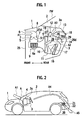
- Figure 1 is a vertical section showing a vehicle air conditioner according to an embodiment of the present invention
- Fig. 2 is an explanatory view showing a vehicle in which the vehicle air conditioner of Fig. 1 is installed
- Fig. 3 is an enlarged view showing a defroster duct of the vehicle air conditioner of Fig. 1
- Fig. 4 is a flowchart showing steps of carrying out ventilation with the vehicle air conditioner of Fig. 1 when one gets in the vehicle
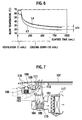
- Fig. 5 is a graph showing average temperatures in tested vehicles in cooling down tests
- Fig. 6 is a graph showing air temperatures sent from vents in the cooling down tests.
- Figure 1 is an enlarged vertical section showing a part A of Fig. 2.
- the vehicle 1 has an engine room or a front compartment and a passenger room or a passenger compartment 2, which are divided by a dash panel 25.
- an instrument panel 3 At a front part of the passenger compartment 2, there is an instrument panel 3.
- An air conditioning unit 4 is disposed in an inside space defined by the instrument panel 3(in a space that is located in front of the instrument panel 3 and behind the dash panel 25).
- the air conditioning unit 4 includes an intake box 8 having a recirculation intake 5, a fresh-air intake 6, and an intake door 7 for opening/closing the intakes 5 and 6, a fan unit 9 connected to a downstream part of the intake box 8, a temperature control unit 11 connected to a downstream part of the fan unit 9 and incorporating a cooling heat exchanger or an evaporator 10, and blow ducts 12,13, and 14 communicating with the downstream of the temperature control unit 11 and the passenger compartment 2.
- the temperature control unit 11 includes the cooling heat exchanger 10 for cooling air, a heating heat exchanger 16 for heating air arranged downstream from the cooling heat exchanger 10, and a mix door 17.
- the mix door 17 is arranged between the cooling heat exchanger 10 and the heating heat exchanger 16, to control air flow ratio between air flowing through the heating heat exchanger 16 and air bypassing the heating heat exchanger 16.
- an air mixing chamber 26 Downstream from the cooling heat exchanger 10 and heating exchanger 16, there is an air mixing chamber 26 to mix cool air from the cooling heat exchanger 10 and hot air from the heating heat exchanger 16. Downstream from the air mixing chamber 26, there are openings 27, 28, and 29 to which the blow ducts 12, 13, 14 are connected, respectively.
- the openings 27, 28, and 29 have blow mode doors 27d, 28d, and 29d to open/close the openings 27, 28, and 29, respectively.
- the blow mode doors 27d, 28d, and 29d are selectively opened/closed to guide conditioned air from the temperature control unit 4 through the blow ducts 12,13, and 14 into the passenger compartment 2.
- the blow duct 12 is a defroster duct that blows conditioned air from the temperature control unit 11 toward a front windshield FW of the passenger compartment 2.
- the blow duct 13 is a vent duct that blows conditioned air from the temperature control unit 11 toward the upper body of a passenger in each front seat.
- the blow duct 14 is a foot duct that blows conditioned air from the temperature control unit 11 toward the lower body of a passenger in each front seat.
- the defroster duct 12 is formed with a communicating port 18 to communicate with the inside and the outside of the defroster duct 12 such that the communicating port 18 communicates with the inside of the defroster duct 12 and the inside of the instrument panel 3.
- the defroster duct 12 incorporates a door 19 to open/close the communicating port 18.
- the communicating port 18 of the defroster duct 12 is diagonally oriented toward an upper rear side of the vehicle 1, more precisely, toward a top wall 3u of the instrument panel 3.
- the defroster duct 12 substantially vertically extends from the temperature control unit 11 toward the top wall 3u of the instrument panel 3.
- An outer wall of the defroster duct 12 includes a front wall 31, a rear wall 34, and left and right side walls (not shown).
- the rear wall 34 is formed with the communicating port 18.
- the rear wall 34 includes a lower wall portion 34a arranged upstream from the communicating port 18 (adjacent to an inlet 12a of the defroster duct 12), an upper wall portion 34b arranged downstream from the communicating port 18 (adjacent to an outlet 12b of the defroster duct 12), and a step wall portion 34c connecting the lower wall portion 34a and upper wall portion 34b to each other, in which the communicating port 18 is formed.
- the lower wall portion 34a is bulged out relative to the upper wall portion 34b toward the rear side of the vehicle such that the step wall portion 34c extends toward the upper front side and faces toward the upper rear side of the vehicle. Therefore, the communicating port 18 formed in the step wall portion 34c is open toward the top wall 3u of the instrument panel 3.
- a rotary shaft 41 of the door 19 is disposed downstream from the communicating port 18 along the defroster duct 12 and at the upper edge of the communicating port 18.
- the door 19 rotates to change the opening ratio between the defroster duct 12 and the communication port 18 such that the opening of the defroster duct 12 becomes larger as the opening of the communication port 18 is made smaller and the opening of the defroster duct 12 becomes smaller as the opening of the communication port 18 is made larger.
- the door 19 fully opens the defroster duct 12 while fully closing the communicating port 18, and fully closes the defroster duct 12 while fully opening the communicating port 18.
- the door 19 points the top wall 3u of the instrument panel 3 to smoothly guide cool air from the communicating port 18 toward the top wall 3u.
- the blow mode door 27d for opening/closing the inlet 12a of the defroster duct 12 has a rotary shaft 42, which is on an extension line X extended from a lower end of the upper wall portion 34b. When fully opened, the blow mode door 27d agrees with the extension line X.
- the external passage 20 communicates with the inside and outside of the vehicle 1, as shown in Fig. 2.
- the external passage 20 is provided with a discharge fan 21 and a door 22.
- the door 22 is, for example, a drafter door that is flexible to be automatically closed in original form and is opened by wind pressure produced when the discharge fan 21 is operated.
- FIG. 4 is a flowchart showing steps of carrying out ventilation with the vehicle air conditioner of Fig. 1 when one gets in the vehicle 1. Namely, the steps shown in Fig. 4 are carried out when it is detected that one gets in the vehicle 1 in response to a signal from an electronic key (not shown) to open/close a door of the vehicle 1.
- Step S 1 determines whether or not a temperature in the passenger compartment 2 is higher than a predetermined temperature (for example, 40°C). If the passenger compartment temperature is higher than the predetermined temperature, step S2 is carried out.
- Step S2 sets the temperature control unit 11 to a fresh air introducing mode (PRE) and establishes a defroster blowing mode by opening the defroster duct 12 and closing the vent duct 13 and foot duct 14.
- PRE fresh air introducing mode
- step S3 sets the fan unit 9 to a maximum air flow to draw fresh air from the fresh-air intake 6.
- step S4 opens the door 19 of the communicating port 18.
- step S5 turns on the discharge fan 21 of the external passage 20.
- step S1 is again carried out With these steps, the communicating port 18 of the defroster duct 12 becomes passable, the intake box 8 is set to the fresh-air introducing mode, and the fan unit 9 is operated. As a result, fresh air having a relatively low temperature is drawn into the vehicle 1 as indicated with an arrow A1.
- the cooling heat exchanger 10 produces cool air, which is sent through the defroster duct 12 to the inside of the instrument panel 3 as indicated with arrows A2 and A3.
- the cool air cools the inside of the instrument panel 3, flows through the passenger compartment 2 from the instrument panel 3 as indicated with an arrow A4, and goes outside from the rear of the passenger compartment 2 as indicated with an arrow A5. In this way, hot air is purged from the passenger compartment 2.
- step S6 determines that the temperature in the passenger compartment 2 is not higher than the predetermined temperature, there is no need of cooling the inside of the instrument panel 3, and therefore, step S6 is carried out Step S6 closes the communicating port 18 with the door 19 and step S7 stops the discharge fan 21 to close the door 22. Thereafter, step S1 is again carried out.
- the embodiment uses cool air generated by the cooling heat exchanger 10 of the temperature control unit 11 to cools the instrument panel 3 and the inside thereof that are at high temperatures to serve as heat sources when a person gets in the vehicle 1 after, for example, the vehicle 1 is parked for a long time under the sun.
- the vehicle air conditioner includes the air conditioning unit disposed in the inside of the instrument panel 3 which includes the temperature control unit 11 incorporating the cooling heat exchanger 10 and the blow ducts 12,13, and 14 connected to the downstream of the temperature control unit 11 and the passenger compartment 2.
- One of the blow ducts (the defroster duct 12 in this embodiment) is formed with the communicating port 18 to communicate with the inside and outside of the defroster duct 12 and includes the door 19 to open/close the communicating port 18.
- the cooling heat exchanger 10 of the temperature control unit 11 generates cool air to cool the inside of the instrument panel 3 that will be a heat source after the vehicle 1 is parked for a long time under the blazing sun.
- the embodiment can improve the cooling ability of the passenger compartment 2 of the vehicle 1.
- the blow duct 12 is provided with the communicating port 18 and door 19. This configuration allows a relatively easy layout designing without changing the existing intake box 8 and temperature control unit 11.
- the inside of the instrument panel 3 is ventilated by drawing fresh air through the ftesh-air intake 6 instead of leakage gaps of the vehicle 1.
- the embodiment can utilize an existing air filter (not shown) in the air conditioning unit 4 to remove smell and dust from fresh air to be drawn into the vehicle 1.
- drawing fresh air through the fresh-air intake 6 involves smaller air-flow resistance, to thereby increase a ventilation flow rate. Accordingly, the embodiment can effectively cool the instrument panel 3 and the inside thereof
- the communicating port 18 faces the top wall 3u of the instrument panel 3. This configuration can blow cool air to the top wall 3u of the instrument panel 3 that is easily heated to high temperatures, and therefore, can improve the cooling efficacy of the vehicle 1.
- the blow duct 12 provided with the communicating port 18 is the defroster duct 12 extending from the temperature control unit 11 toward the top wall 3u of the instrument panel 3.
- the defroster duct 12 allows the communicating port 18 to be located closer to the top wall 3u of the instrument panel 3, to effectively cool the top wall 3u.
- the step wall portion 34c connects the lower wall portion 34a and upper wall portion 34b to each other and is formed with the communicating port 18.
- the lower wall portion 34a is off to the outside relative to the upper wall portion 34b. This arrangement allows the communicating port 18 to orient the top wall 3u of the instrument panel 3.
- This simple configuration enables the upwardly oriented blow duct 12 to be provided with the communicating port 18 facing the top wall 3u of the instrument panel 3. Since the lower wall portion 34a upstream from the communicating port 18 is bulged out, air smoothly flows toward the communicating port 18, to easily maintain a large flow rate of cool air passing through the communicating port 18.
- the door 19 has the rotary shaft 41 that is arranged downstream from the communicating port 18 (on the outlet 12b side of the communicating port 18), so that the door 19 may entirely open the blow duct 12 while entirely closing the communicating port 18, or entirely close the blow duct 12 while wholly opening the communicating port 18.
- the door 19 points the top wall 3u of the instrument panel 3.
- cool air from the communicating port 18 can smoothly be guided to the top wall 3u of the instrument panel 3, i.e., a large quantity of cool air can hit the top wall 3u of the instrument panel 3 to improve the cooling effect.
- the blow mode door 27d for opening/closing the inlet 12a of the blow duct 12 is arranged upstream from the door 19.
- the blow mode door 27d has the rotary shaft 42 that is on the extension line X extended from a lower end of the upper wall portion 34b.
- blow mode door 27d When opened, the blow mode door 27d provides a regulating effect to provide a smooth air flow. This results in improving the cooling effect of the top wall 3u of the instrument panel 3.
- the external passage 20 is separately arranged from the fresh-air intake 6 of the intake box 8 and has the discharge fan 21 to forcibly discharge air from the passenger compartment 2.
- This configuration improves a ventilation flow rate to effectively cool the instrument panel 3 and the inside thereof
- the external passage 20 is arranged at the rear of the passenger compartment 2. Accordingly, cool air blown into the inside of the instrument panel 3 that is at the front of the passenger compartment 2 flows from the front to the rear of the passenger compartment 2 and is discharged from the external passage 20 at the rear of the passenger compartment 2 to the outside of the vehicle 1. With this, heated air in the whole passenger compartment 2 is purged out to the outside of the vehicle. This results in further improving the cooling performance of the passenger compartment 2.
- the applicant of the present invention carried out cooling down tests at an ambient temperature of 40°C, a humidity of 50%, and a solar irradiance of 1046 W. Under these conditions, the vehicle 1 was left for 60 minutes. Thereafter, the vehicle air conditioner of the embodiment was operated for one minute to ventilate the inside of the instrument panel 3, and then, a normal cooling operation was carried out for ten minutes. According to the tests, average temperatures in the tested room (passenger compartment 2) changed as indicated with a curve L1 shown in Fig. 5 and blow temperatures from temperature control unit changed as indicated with a curve L3 shown in Fig. 6. When no ventilation of the embodiment was conducted, average temperatures in the tested room (passenger compartment 2) changed as indicated with a curve L2 shown in Fig.
- the above-mentioned embodiment arranges the communicating port 18 and door 19 in the defroster duct 12 that is oriented toward the front windshield FW of the passenger compartment 2.
- the temperature control unit 11 may have a communicating port communicating with the inside and outside of the temperature control unit 11 and a door for opening/closing the port.
- the vent duct 13 that is oriented toward the upper half of a passenger in each front seat in the passenger compartment 2 may have a communicating port communicating with the inside and outside of the vent duct 13 and a door for opening/closing the port.
- the foot duct 14 that is oriented toward the lower half of a passenger in each front seat in the passenger compartment 2 may have a communicating port communicating with the inside and outside of the foot duct 14 and a door for opening/closing the port. It is preferable to form the communicating port in the vent duct 13or in the defroster duct 12 than to form the same in the foot duct 14, so that the communicating port is located in the vicinity of the top wall 3u of the instrument panel 3 that is easily heated to high temperatures. Like the embodiment, it is more preferable to form the communicating port in the defroster duct 12 that is above the temperature control unit 11 than to form the same in the vent duct 13, so that the communicating port may be closer to the top wall 3u of the instrument panel 3.
- the door 22 of the external passage 20 is a drafter door that automatically closes due to its own flexibility and opens due to wind pressure produced when the discharge fan 21 operates.
- the drafter door it is possible to use a door that automatically closes due to its own weight, or any other door.
Landscapes
- Engineering & Computer Science (AREA)
- Mechanical Engineering (AREA)
- Physics & Mathematics (AREA)
- Thermal Sciences (AREA)
- Air-Conditioning For Vehicles (AREA)
Abstract
Description
- This application is based upon and claims the benefit of priority from the prior
Japanese Patent Application No. 2006-226738 - The present invention relates to a vehicle air conditioner to condition air in a passenger compartment of a vehicle.
- If a vehicle is parked for a long time under the blazing sun, an instrument panel at a front part of a passenger compartment of the vehicle is heated to very high temperatures (50 to 70°C) with sunrays transmitted through a front windshield at the front part of the passenger compartment. When starting such a vehicle, the instrument panel serves as a heat source to prevent the passenger compartment from being efficiently cooled.
- A related art (see
Japanese Unexamined Patent Application Publication No. 2005-186860 intake box 101 has a fresh-air intake 102, arecirculation intake 103, and adoor 104 to open/close theintakes intake box 101 is connected to afan unit 115. A downstream part of thefan unit 115 is connected to atemperature control unit 117. The fresh-air intake 102 of theintake box 101 communicates through a fresh-air passage 105 with a fresh-air intake 113 of a cowl box that is exposed to the outside of the vehicle. An intermediate part of the fresh-air passage 105 is connected to an outlet of avent passage 106. An inlet of thevent passage 106 is exposed to the inside of theinstrument panel 107. Thevent passage 106 includes afan 108 and is opened/closed with adoor 109. - This related art operates a recirculation mode by opening the
recirculation intake 103 of theintake box 101, closing the fresh-air intake 102 thereof, opening thedoor 109 of thevent passage 106, and activating thefan 108. In the recirculation mode, heatedair 110 inside theinstrument panel 107 is drawn into thevent passage 106, is reversely passed (seearrows 111 in Fig. 7) through the fresh-air passage 105, and is discharged outside from the fresh-air intake 113 of the cowl box. - The above-mentioned related art may remove
heated air 110 from the inside of theinstrument panel 107 to the outside of the vehicle via thevent passage 106, the fresh-air intake 105, and the fresh-air intake 113 of the cowl box. The related art, however, has little effect of cooling theheated instrument panel 107 and the inside thereof. - In a limited narrow space in the vicinity of the
intake box 101, there are arranged thevent passage 106,fan 108, anddoor 109, and therefore, the related art must find a proper layout. This raises a problem of complicating the layout designing. When thedoor 104 is operated to open therecirculation intake 103 of theintake box 101 and close the fresh-air intake 102 and thefan 108 is turned on,air 110 inside theinstrument panel 107 is drawn into thevent passage 106 to produce a negative pressure inside theinstrument panel 107. The negative pressure draws fresh air through leakage gaps of the body of the vehicle. The leakage gaps have large air-flow resistance to make a ventilation flow rate insufficient At the same time, the leakage gaps may introduce outside smell and dust into the vehicle. - In consideration of the problems of the related art, an object of the present invention is to provide a vehicle air conditioner capable of efficiently cooling an instrument panel and the inside thereof
- An aspect of the present invention provides a vehicle air conditioner comprising: an intake box provided in an inside of an instrument panel at a front part of a passenger compartment of a vehicle and having a recirculation intake, a fresh-air intake, and an intake door for opening/closing the intakes; a fan unit provided in the inside of the instrument panel and connected to the downstream of the intake box; a temperature control unit provided in the inside of the instrument panel and connected to the downstream of the fan unit and incorporating a cooling heat exchanger, a blow duct provided in the inside of the instrument panel and connecting the temperature control unit and the passenger compartment such that air flows from the temperature control unit to the passenger compartment via the blow duct; a communicating port formed at the blow duct or the temperature control unit and configured to communicate with the inside of the instrument panel; and a door configured to open/close the communicating port.
-
- Figure 1 is a vertical section showing a vehicle air conditioner according to an embodiment of the present invention;
- Figure 2 is an explanatory view showing a vehicle in which the vehicle air conditioner of Figs. 1 is installed;
- Figure 3 is an enlarged view showing a defroster duct of the vehicle air conditioner of Fig. 1;
- Figure 4 is a flowchart showing steps of carrying out ventilation with the vehicle air conditioner of Fig. 1 when one gets in the vehicle;
- Figure 5 is a graph showing average temperatures in tested vehicles in cooling down tests;
- Figure 6 is a graph showing vent blow temperatures in the cooling down tests; and
- Figure 7 is a vertical section showing a vehicle air conditioner according to a related art.
- A vehicle air conditioner according to an embodiment of the present invention will be explained with reference to drawings.
- Figure 1 is a vertical section showing a vehicle air conditioner according to an embodiment of the present invention, Fig. 2 is an explanatory view showing a vehicle in which the vehicle air conditioner of Fig. 1 is installed, Fig. 3 is an enlarged view showing a defroster duct of the vehicle air conditioner of Fig. 1, Fig. 4 is a flowchart showing steps of carrying out ventilation with the vehicle air conditioner of Fig. 1 when one gets in the vehicle, Fig. 5 is a graph showing average temperatures in tested vehicles in cooling down tests, and Fig. 6 is a graph showing air temperatures sent from vents in the cooling down tests. Figure 1 is an enlarged vertical section showing a part A of Fig. 2.
- In Figs. 1 and 2, the
vehicle 1 has an engine room or a front compartment and a passenger room or apassenger compartment 2, which are divided by adash panel 25. At a front part of thepassenger compartment 2, there is aninstrument panel 3. Anair conditioning unit 4 is disposed in an inside space defined by the instrument panel 3(in a space that is located in front of theinstrument panel 3 and behind the dash panel 25). Theair conditioning unit 4 includes anintake box 8 having arecirculation intake 5, a fresh-air intake 6, and anintake door 7 for opening/closing theintakes intake box 8, atemperature control unit 11 connected to a downstream part of the fan unit 9 and incorporating a cooling heat exchanger or anevaporator 10, andblow ducts temperature control unit 11 and thepassenger compartment 2. Thetemperature control unit 11 includes thecooling heat exchanger 10 for cooling air, aheating heat exchanger 16 for heating air arranged downstream from thecooling heat exchanger 10, and amix door 17. Themix door 17 is arranged between thecooling heat exchanger 10 and theheating heat exchanger 16, to control air flow ratio between air flowing through theheating heat exchanger 16 and air bypassing theheating heat exchanger 16. - Downstream from the
cooling heat exchanger 10 andheating exchanger 16, there is anair mixing chamber 26 to mix cool air from thecooling heat exchanger 10 and hot air from theheating heat exchanger 16. Downstream from theair mixing chamber 26, there areopenings blow ducts openings blow mode doors openings blow mode doors temperature control unit 4 through theblow ducts passenger compartment 2. - The
blow duct 12 is a defroster duct that blows conditioned air from thetemperature control unit 11 toward a front windshield FW of thepassenger compartment 2. Theblow duct 13 is a vent duct that blows conditioned air from thetemperature control unit 11 toward the upper body of a passenger in each front seat. Theblow duct 14 is a foot duct that blows conditioned air from thetemperature control unit 11 toward the lower body of a passenger in each front seat. - According to the embodiment, the
defroster duct 12 is formed with a communicatingport 18 to communicate with the inside and the outside of thedefroster duct 12 such that the communicatingport 18 communicates with the inside of thedefroster duct 12 and the inside of theinstrument panel 3. Thedefroster duct 12 incorporates adoor 19 to open/close the communicatingport 18. The communicatingport 18 of thedefroster duct 12 is diagonally oriented toward an upper rear side of thevehicle 1, more precisely, toward atop wall 3u of theinstrument panel 3. - With reference to Fig. 3, the
defroster duct 12 will be explained in detail. Thedefroster duct 12 substantially vertically extends from thetemperature control unit 11 toward thetop wall 3u of theinstrument panel 3. An outer wall of thedefroster duct 12 includes afront wall 31, arear wall 34, and left and right side walls (not shown). Therear wall 34 is formed with the communicatingport 18. Therear wall 34 includes alower wall portion 34a arranged upstream from the communicating port 18 (adjacent to aninlet 12a of the defroster duct 12), anupper wall portion 34b arranged downstream from the communicating port 18 (adjacent to anoutlet 12b of the defroster duct 12), and astep wall portion 34c connecting thelower wall portion 34a andupper wall portion 34b to each other, in which the communicatingport 18 is formed. - The
lower wall portion 34a is bulged out relative to theupper wall portion 34b toward the rear side of the vehicle such that thestep wall portion 34c extends toward the upper front side and faces toward the upper rear side of the vehicle. Therefore, the communicatingport 18 formed in thestep wall portion 34c is open toward thetop wall 3u of theinstrument panel 3. - A
rotary shaft 41 of thedoor 19 is disposed downstream from the communicatingport 18 along thedefroster duct 12 and at the upper edge of the communicatingport 18. Thedoor 19 rotates to change the opening ratio between thedefroster duct 12 and thecommunication port 18 such that the opening of thedefroster duct 12 becomes larger as the opening of thecommunication port 18 is made smaller and the opening of thedefroster duct 12 becomes smaller as the opening of thecommunication port 18 is made larger. Thedoor 19 fully opens thedefroster duct 12 while fully closing the communicatingport 18, and fully closes thedefroster duct 12 while fully opening the communicatingport 18. When closing thedefroster duct 12 and opening the communicatingport 18, thedoor 19 points thetop wall 3u of theinstrument panel 3 to smoothly guide cool air from the communicatingport 18 toward thetop wall 3u. - The
blow mode door 27d for opening/closing theinlet 12a of thedefroster duct 12 has arotary shaft 42, which is on an extension line X extended from a lower end of theupper wall portion 34b. When fully opened, theblow mode door 27d agrees with the extension line X. - At the rear of the
passenger compartment 2, there is anexternal passage 20 communicating with the inside and outside of thevehicle 1, as shown in Fig. 2. Theexternal passage 20 is provided with adischarge fan 21 and a door 22. The door 22 is, for example, a drafter door that is flexible to be automatically closed in original form and is opened by wind pressure produced when thedischarge fan 21 is operated. - Figure 4 is a flowchart showing steps of carrying out ventilation with the vehicle air conditioner of Fig. 1 when one gets in the
vehicle 1. Namely, the steps shown in Fig. 4 are carried out when it is detected that one gets in thevehicle 1 in response to a signal from an electronic key (not shown) to open/close a door of thevehicle 1.Step S 1 determines whether or not a temperature in thepassenger compartment 2 is higher than a predetermined temperature (for example, 40°C). If the passenger compartment temperature is higher than the predetermined temperature, step S2 is carried out. Step S2 sets thetemperature control unit 11 to a fresh air introducing mode (PRE) and establishes a defroster blowing mode by opening thedefroster duct 12 and closing thevent duct 13 andfoot duct 14. Thereafter, step S3 sets the fan unit 9 to a maximum air flow to draw fresh air from the fresh-air intake 6. Step S4 opens thedoor 19 of the communicatingport 18. Step S5 turns on thedischarge fan 21 of theexternal passage 20. Thereafter, step S1 is again carried out With these steps, the communicatingport 18 of thedefroster duct 12 becomes passable, theintake box 8 is set to the fresh-air introducing mode, and the fan unit 9 is operated. As a result, fresh air having a relatively low temperature is drawn into thevehicle 1 as indicated with an arrow A1. At the same time, thecooling heat exchanger 10 produces cool air, which is sent through thedefroster duct 12 to the inside of theinstrument panel 3 as indicated with arrows A2 and A3. The cool air cools the inside of theinstrument panel 3, flows through thepassenger compartment 2 from theinstrument panel 3 as indicated with an arrow A4, and goes outside from the rear of thepassenger compartment 2 as indicated with an arrow A5. In this way, hot air is purged from thepassenger compartment 2. - If step S2 determines that the temperature in the
passenger compartment 2 is not higher than the predetermined temperature, there is no need of cooling the inside of theinstrument panel 3, and therefore, step S6 is carried out Step S6 closes the communicatingport 18 with thedoor 19 and step S7 stops thedischarge fan 21 to close the door 22. Thereafter, step S1 is again carried out. - In this way, the embodiment uses cool air generated by the
cooling heat exchanger 10 of thetemperature control unit 11 to cools theinstrument panel 3 and the inside thereof that are at high temperatures to serve as heat sources when a person gets in thevehicle 1 after, for example, thevehicle 1 is parked for a long time under the sun. - According to the embodiment, the vehicle air conditioner includes the air conditioning unit disposed in the inside of the
instrument panel 3 which includes thetemperature control unit 11 incorporating thecooling heat exchanger 10 and theblow ducts temperature control unit 11 and thepassenger compartment 2. One of the blow ducts (thedefroster duct 12 in this embodiment) is formed with the communicatingport 18 to communicate with the inside and outside of thedefroster duct 12 and includes thedoor 19 to open/close the communicatingport 18. - The
cooling heat exchanger 10 of thetemperature control unit 11 generates cool air to cool the inside of theinstrument panel 3 that will be a heat source after thevehicle 1 is parked for a long time under the blazing sun. The embodiment can improve the cooling ability of thepassenger compartment 2 of thevehicle 1. According to the embodiment, theblow duct 12 is provided with the communicatingport 18 anddoor 19. This configuration allows a relatively easy layout designing without changing the existingintake box 8 andtemperature control unit 11. - According to the embodiment, the inside of the
instrument panel 3 is ventilated by drawing fresh air through the ftesh-air intake 6 instead of leakage gaps of thevehicle 1. Accordingly, the embodiment can utilize an existing air filter (not shown) in theair conditioning unit 4 to remove smell and dust from fresh air to be drawn into thevehicle 1. Compared with drawing fresh air through the leakage gaps of thevehicle 1, drawing fresh air through the fresh-air intake 6 involves smaller air-flow resistance, to thereby increase a ventilation flow rate. Accordingly, the embodiment can effectively cool theinstrument panel 3 and the inside thereof - According to the embodiment, the communicating
port 18 faces thetop wall 3u of theinstrument panel 3. This configuration can blow cool air to thetop wall 3u of theinstrument panel 3 that is easily heated to high temperatures, and therefore, can improve the cooling efficacy of thevehicle 1. - According to the embodiment, the
blow duct 12 provided with the communicatingport 18 is thedefroster duct 12 extending from thetemperature control unit 11 toward thetop wall 3u of theinstrument panel 3. Compared with the other blow ducts (ventduct 13 and foot duct 14), thedefroster duct 12 allows the communicatingport 18 to be located closer to thetop wall 3u of theinstrument panel 3, to effectively cool thetop wall 3u. - According to the embodiment, the
wall 34 of theblow duct 12 in which the communicatingport 18 includes thelower wall portion 34a arranged upstream from the communicatingport 18, theupper wall portion 34b arranged downstream from the communicatingport 18, and thestep wall portion 34c. Thestep wall portion 34c connects thelower wall portion 34a andupper wall portion 34b to each other and is formed with the communicatingport 18. Thelower wall portion 34a is off to the outside relative to theupper wall portion 34b. This arrangement allows the communicatingport 18 to orient thetop wall 3u of theinstrument panel 3. - This simple configuration enables the upwardly oriented
blow duct 12 to be provided with the communicatingport 18 facing thetop wall 3u of theinstrument panel 3. Since thelower wall portion 34a upstream from the communicatingport 18 is bulged out, air smoothly flows toward the communicatingport 18, to easily maintain a large flow rate of cool air passing through the communicatingport 18. - According to the embodiment, the
door 19 has therotary shaft 41 that is arranged downstream from the communicating port 18 (on theoutlet 12b side of the communicating port 18), so that thedoor 19 may entirely open theblow duct 12 while entirely closing the communicatingport 18, or entirely close theblow duct 12 while wholly opening the communicatingport 18. When closing theblow duct 12 and opening the communicatingport 18, thedoor 19 points thetop wall 3u of theinstrument panel 3. - As a result, cool air from the communicating
port 18 can smoothly be guided to thetop wall 3u of theinstrument panel 3, i.e., a large quantity of cool air can hit thetop wall 3u of theinstrument panel 3 to improve the cooling effect. - According to the embodiment, the
blow mode door 27d for opening/closing theinlet 12a of theblow duct 12 is arranged upstream from thedoor 19. Theblow mode door 27d has therotary shaft 42 that is on the extension line X extended from a lower end of theupper wall portion 34b. - When opened, the
blow mode door 27d provides a regulating effect to provide a smooth air flow. This results in improving the cooling effect of thetop wall 3u of theinstrument panel 3. - According to the embodiment, the
external passage 20 is separately arranged from the fresh-air intake 6 of theintake box 8 and has thedischarge fan 21 to forcibly discharge air from thepassenger compartment 2. This configuration improves a ventilation flow rate to effectively cool theinstrument panel 3 and the inside thereof - According to the embodiment, the
external passage 20 is arranged at the rear of thepassenger compartment 2. Accordingly, cool air blown into the inside of theinstrument panel 3 that is at the front of thepassenger compartment 2 flows from the front to the rear of thepassenger compartment 2 and is discharged from theexternal passage 20 at the rear of thepassenger compartment 2 to the outside of thevehicle 1. With this, heated air in thewhole passenger compartment 2 is purged out to the outside of the vehicle. This results in further improving the cooling performance of thepassenger compartment 2. - The applicant of the present invention carried out cooling down tests at an ambient temperature of 40°C, a humidity of 50%, and a solar irradiance of 1046 W. Under these conditions, the
vehicle 1 was left for 60 minutes. Thereafter, the vehicle air conditioner of the embodiment was operated for one minute to ventilate the inside of theinstrument panel 3, and then, a normal cooling operation was carried out for ten minutes. According to the tests, average temperatures in the tested room (passenger compartment 2) changed as indicated with a curve L1 shown in Fig. 5 and blow temperatures from temperature control unit changed as indicated with a curve L3 shown in Fig. 6. When no ventilation of the embodiment was conducted, average temperatures in the tested room (passenger compartment 2) changed as indicated with a curve L2 shown in Fig. 5 and blow temperatures from temperature control unit changed as indicated with a curve L5 shown in Fig. 6. Compared with conducting no ventilation, conducting the ventilation of the embodiment shows an average room temperature difference ΔT1 of about 2°C (Fig. 5) and a blow temperature difference ΔT2 of about 8°C (Fig. 6). This confirms that executing ventilation by the vehicle air conditioner according to the embodiment when a person gets in thevehicle 1 improves the cooling efficiency of thepassenger compartment 2. - The above-mentioned embodiment arranges the communicating
port 18 anddoor 19 in thedefroster duct 12 that is oriented toward the front windshield FW of thepassenger compartment 2. This does not limit the present invention. Thetemperature control unit 11 may have a communicating port communicating with the inside and outside of thetemperature control unit 11 and a door for opening/closing the port. Thevent duct 13 that is oriented toward the upper half of a passenger in each front seat in thepassenger compartment 2 may have a communicating port communicating with the inside and outside of thevent duct 13 and a door for opening/closing the port. Thefoot duct 14 that is oriented toward the lower half of a passenger in each front seat in thepassenger compartment 2 may have a communicating port communicating with the inside and outside of thefoot duct 14 and a door for opening/closing the port. It is preferable to form the communicating port in the vent duct 13or in thedefroster duct 12 than to form the same in thefoot duct 14, so that the communicating port is located in the vicinity of thetop wall 3u of theinstrument panel 3 that is easily heated to high temperatures. Like the embodiment, it is more preferable to form the communicating port in thedefroster duct 12 that is above thetemperature control unit 11 than to form the same in thevent duct 13, so that the communicating port may be closer to thetop wall 3u of theinstrument panel 3. - According to the embodiment, the door 22 of the
external passage 20 is a drafter door that automatically closes due to its own flexibility and opens due to wind pressure produced when thedischarge fan 21 operates. Instead of the drafter door, it is possible to use a door that automatically closes due to its own weight, or any other door. - Although the present invention has been explained with reference to certain embodiments, the present invention is not limited to the embodiments. Modifications and variations of the embodiments can be made without departing from the spirit and scope of the appended claims. The embodiments, therefore, are only for illustrative purposes and are not intended to limit the present invention.
Claims (8)
- A vehicle air conditioner comprising:an intake box (8) provided in an inside of an instrument panel (3) at a front part of a passenger compartment (2) of a vehicle and having a recirculation intake (5), a fresh-air intake (6), and an intake door (7) for opening/closing the intakes (5,6);a fan unit (9) provided in the inside of the instrument panel (3) and connected to the downstream of the intake box (8);a temperature control unit (11) provided in the inside of the instrument panel (3) and connected to the downstream of the fan unit (9) and incorporating a cooling heat exchanger (10);a blow duct (12,13,14) provided in the inside of the instrument panel (3) and connecting the temperature control unit (11) and the passenger compartment (2) such that air flows from the temperature control unit (11) to the passenger compartment (2) via the blow duct (12,13,14);a communicating port (18) formed at the blow duct (12) or the temperature control unit and configured to communicate with the inside of the instrument panel (3); anda door (19) configured to open/close the communicating port (18).
- The vehicle air conditioner according to claim 1, wherein:the communicating port is formed at the temperature control unit (11) and oriented toward the top wall (3u) of the instrument panel (3).
- The vehicle air conditioner according to claim 1, wherein:the communicating port (18) is formed at the blow duct (12) which extends from the temperature control unit (11) toward a top wall (3u) of the instrument panel (3); andthe communicating port (18) is oriented toward the top wall (3u) of the instrument panel (3).
- The vehicle air conditioner according to claim 3, wherein:the blow duct (12) includes a wall (34) in which the communicating port (18) is formed,the wall (34) comprises a lower wall portion (34a) upstream from the communicating port and an upper wall portion (34b) downstream from the communicating port, andthe lower wall portion is bulged out relative to the upper wall portion.
- The vehicle air conditioner according to claim 3, wherein:the door (19) has a rotary shaft (41) downstream from the communicating port (18) and is configured to point the top wall (3u) of the instrument panel (3) while closing the blow duct (12) and opening the communicating port (18).
- The vehicle air conditioner according to claim 5, further comprising:a blow mode door (27d) arranged upstream from the door (19) and configured to open/close the blow duct (12), a rotary shaft (42) of the blow mode door (27d) disposed on an extension line (X) of a lower end of the upper wall portion (34b).
- The vehicle air conditioner according to claim 1, further comprising:an external passage (20) communicating with the inside and outside of the vehicle, the external passage (20) being provided with a discharge fan (21) configured to blow air through the external passage (20) and a door (22) configured to open and close the external passage (20).
- The vehicle air conditioner according to claim 7, wherein:the external passage (20) is arranged at a rear part of the passenger compartment (2).
Applications Claiming Priority (1)
| Application Number | Priority Date | Filing Date | Title |
|---|---|---|---|
| JP2006226738A JP2008049782A (en) | 2006-08-23 | 2006-08-23 | Vehicle air conditioner |
Publications (1)
| Publication Number | Publication Date |
|---|---|
| EP1892131A1 true EP1892131A1 (en) | 2008-02-27 |
Family
ID=38606660
Family Applications (1)
| Application Number | Title | Priority Date | Filing Date |
|---|---|---|---|
| EP07016292A Withdrawn EP1892131A1 (en) | 2006-08-23 | 2007-08-20 | Vehicle air conditioner |
Country Status (4)
| Country | Link |
|---|---|
| US (1) | US20080066480A1 (en) |
| EP (1) | EP1892131A1 (en) |
| JP (1) | JP2008049782A (en) |
| CN (1) | CN101130336A (en) |
Cited By (1)
| Publication number | Priority date | Publication date | Assignee | Title |
|---|---|---|---|---|
| US20160236534A1 (en) * | 2013-10-14 | 2016-08-18 | Weidplas Gmbh | Motor vehicle having an air-conditioning system |
Families Citing this family (13)
| Publication number | Priority date | Publication date | Assignee | Title |
|---|---|---|---|---|
| DE102006020377A1 (en) * | 2006-04-28 | 2007-10-31 | Behr Gmbh & Co. Kg | Vehicle air conditioner with heater and evaporator contained in air guidance casing, inclines them at acute angle to horizontal plane, with optional partial overlap |
| IT1401209B1 (en) * | 2010-07-02 | 2013-07-12 | Cnh Italia Spa | CABIN FOR AGRICULTURAL VEHICLE EQUIPPED WITH A VENTILATION AND AIR-CONDITIONING SYSTEM |
| JP5625993B2 (en) * | 2011-02-22 | 2014-11-19 | 株式会社デンソー | Air conditioner for vehicles |
| JP5785840B2 (en) * | 2011-09-29 | 2015-09-30 | 富士重工業株式会社 | Vehicle, cooling device, and cooling method |
| JP6134535B2 (en) * | 2013-02-26 | 2017-05-24 | 株式会社ケーヒン | Air conditioner for vehicles |
| JP6223710B2 (en) * | 2013-05-16 | 2017-11-01 | 株式会社日本クライメイトシステムズ | Air conditioner for vehicles |
| US9925844B2 (en) * | 2013-08-08 | 2018-03-27 | Denso International America, Inc. | Two door structure for partial recirculation in an air conditioning system |
| JP6015607B2 (en) * | 2013-09-18 | 2016-10-26 | 株式会社デンソー | Air conditioning unit for vehicles |
| DE102014211529B4 (en) * | 2014-06-17 | 2016-02-18 | Ford Global Technologies, Llc | Method and device for operating a heat accumulator in a motor vehicle |
| CN108394251A (en) * | 2018-03-28 | 2018-08-14 | 艾泰斯热系统研发(上海)有限公司 | The air-conditioning system and control method of reversed arrangement |
| US20190366795A1 (en) * | 2018-06-05 | 2019-12-05 | GM Global Technology Operations LLC | Cooling assembly and a passenger compartment for a vehicle that utilizes the cooling assembly |
| US10906477B2 (en) | 2019-04-04 | 2021-02-02 | Nissan North America, Inc. | Vehicle passenger compartment vent structure |
| US11148507B2 (en) | 2019-04-04 | 2021-10-19 | Nissan North America, Inc. | Vehicle passenger compartment vent structure |
Citations (4)
| Publication number | Priority date | Publication date | Assignee | Title |
|---|---|---|---|---|
| FR2805778A1 (en) * | 2000-03-06 | 2001-09-07 | Valeo Climatisation | Procedure and device, for diffusing air flow into passenger compartment of vehicle, consists of fan with outlet pipe, with diffusing panel to produce air flow at speed, within defined range |
| EP1132232A1 (en) * | 2000-03-06 | 2001-09-12 | Valeo Climatisation | Heat and/or air conditioning device with at least one outlet for defrosting |
| US20040031279A1 (en) | 2002-08-09 | 2004-02-19 | Tomohiro Kamiya | Air conditioning system |
| JP2005186860A (en) | 2003-12-26 | 2005-07-14 | Zexel Valeo Climate Control Corp | Vehicular ventilating device |
Family Cites Families (2)
| Publication number | Priority date | Publication date | Assignee | Title |
|---|---|---|---|---|
| JPH0238131A (en) * | 1988-07-29 | 1990-02-07 | Sanden Corp | Air conditioner for vehicle |
| JP3885681B2 (en) * | 2002-07-29 | 2007-02-21 | 日産自動車株式会社 | Air conditioner for vehicles |
-
2006
- 2006-08-23 JP JP2006226738A patent/JP2008049782A/en not_active Withdrawn
-
2007
- 2007-08-20 EP EP07016292A patent/EP1892131A1/en not_active Withdrawn
- 2007-08-22 US US11/892,412 patent/US20080066480A1/en not_active Abandoned
- 2007-08-23 CN CN200710146162.6A patent/CN101130336A/en active Pending
Patent Citations (4)
| Publication number | Priority date | Publication date | Assignee | Title |
|---|---|---|---|---|
| FR2805778A1 (en) * | 2000-03-06 | 2001-09-07 | Valeo Climatisation | Procedure and device, for diffusing air flow into passenger compartment of vehicle, consists of fan with outlet pipe, with diffusing panel to produce air flow at speed, within defined range |
| EP1132232A1 (en) * | 2000-03-06 | 2001-09-12 | Valeo Climatisation | Heat and/or air conditioning device with at least one outlet for defrosting |
| US20040031279A1 (en) | 2002-08-09 | 2004-02-19 | Tomohiro Kamiya | Air conditioning system |
| JP2005186860A (en) | 2003-12-26 | 2005-07-14 | Zexel Valeo Climate Control Corp | Vehicular ventilating device |
Cited By (1)
| Publication number | Priority date | Publication date | Assignee | Title |
|---|---|---|---|---|
| US20160236534A1 (en) * | 2013-10-14 | 2016-08-18 | Weidplas Gmbh | Motor vehicle having an air-conditioning system |
Also Published As
| Publication number | Publication date |
|---|---|
| US20080066480A1 (en) | 2008-03-20 |
| JP2008049782A (en) | 2008-03-06 |
| CN101130336A (en) | 2008-02-27 |
Similar Documents
| Publication | Publication Date | Title |
|---|---|---|
| EP1892131A1 (en) | Vehicle air conditioner | |
| US9956846B2 (en) | Partial recirculation vehicle HVAC system | |
| US4376408A (en) | Air circulation system in a vehicle compartment of an automotive vehicle | |
| US7905278B2 (en) | Vehicular air conditioner | |
| JP5631809B2 (en) | Air conditioner for vehicles | |
| JP6414344B2 (en) | Airflow control system | |
| JP2010076506A (en) | Air conditioner for vehicle | |
| US20140335774A1 (en) | Convex grid shape to reduce turbulence under rotary door | |
| CN217374074U (en) | Rear exhaust duct structure of vehicle-mounted air conditioner, vehicle-mounted air conditioner and automobile | |
| JP4687435B2 (en) | Air conditioner for vehicles | |
| KR20070023073A (en) | An air-conditioning system of bus | |
| JP2010013056A (en) | Air conditioning device for vehicle | |
| JP2006264430A (en) | Vehicular ventilator | |
| JP7262252B2 (en) | air conditioning unit for vehicle | |
| KR101703203B1 (en) | Air conditioning system for electric automotive vehicles | |
| KR200442465Y1 (en) | Vent Door for Air Conditioner Unit of Vehicle | |
| JP2518661Y2 (en) | Intake unit of automobile air conditioner | |
| JP2003285621A (en) | Air conditioner for vehicle | |
| JPH055515U (en) | Automotive air conditioner heater unit | |
| JPS5921927Y2 (en) | Vehicle air conditioner | |
| JP2006193089A (en) | Vehicular ventilation device | |
| JP2010069920A (en) | Automobile air-conditioner | |
| KR20110024141A (en) | Air conditioner for vehicles | |
| JP2007307974A (en) | Vehicular air-conditioner | |
| KR20100011633A (en) | A radiator cooling system for a rear engine bus |
Legal Events
| Date | Code | Title | Description |
|---|---|---|---|
| PUAI | Public reference made under article 153(3) epc to a published international application that has entered the european phase |
Free format text: ORIGINAL CODE: 0009012 |
|
| AK | Designated contracting states |
Kind code of ref document: A1 Designated state(s): AT BE BG CH CY CZ DE DK EE ES FI FR GB GR HU IE IS IT LI LT LU LV MC MT NL PL PT RO SE SI SK TR |
|
| AX | Request for extension of the european patent |
Extension state: AL BA HR MK YU |
|
| 17P | Request for examination filed |
Effective date: 20080604 |
|
| 17Q | First examination report despatched |
Effective date: 20080709 |
|
| AKX | Designation fees paid |
Designated state(s): DE FR GB |
|
| STAA | Information on the status of an ep patent application or granted ep patent |
Free format text: STATUS: THE APPLICATION IS DEEMED TO BE WITHDRAWN |
|
| 18D | Application deemed to be withdrawn |
Effective date: 20100415 |