EP1892061A1 - Nail driving device, attachment therfore and method - Google Patents
Nail driving device, attachment therfore and method Download PDFInfo
- Publication number
- EP1892061A1 EP1892061A1 EP07016316A EP07016316A EP1892061A1 EP 1892061 A1 EP1892061 A1 EP 1892061A1 EP 07016316 A EP07016316 A EP 07016316A EP 07016316 A EP07016316 A EP 07016316A EP 1892061 A1 EP1892061 A1 EP 1892061A1
- Authority
- EP
- European Patent Office
- Prior art keywords
- nail
- attachment
- driving device
- barrel
- nails
- Prior art date
- Legal status (The legal status is an assumption and is not a legal conclusion. Google has not performed a legal analysis and makes no representation as to the accuracy of the status listed.)
- Granted
Links
Images


Classifications
-
- B—PERFORMING OPERATIONS; TRANSPORTING
- B25—HAND TOOLS; PORTABLE POWER-DRIVEN TOOLS; MANIPULATORS
- B25C—HAND-HELD NAILING OR STAPLING TOOLS; MANUALLY OPERATED PORTABLE STAPLING TOOLS
- B25C1/00—Hand-held nailing tools; Nail feeding devices
- B25C1/08—Hand-held nailing tools; Nail feeding devices operated by combustion pressure
- B25C1/10—Hand-held nailing tools; Nail feeding devices operated by combustion pressure generated by detonation of a cartridge
- B25C1/18—Details and accessories, e.g. splinter guards, spall minimisers
- B25C1/188—Arrangements at the forward end of the barrel, e.g. splinter guards, spall minimisers, safety arrangements, silencers, bolt retainers
-
- B—PERFORMING OPERATIONS; TRANSPORTING
- B25—HAND TOOLS; PORTABLE POWER-DRIVEN TOOLS; MANIPULATORS
- B25C—HAND-HELD NAILING OR STAPLING TOOLS; MANUALLY OPERATED PORTABLE STAPLING TOOLS
- B25C5/00—Manually operated portable stapling tools; Hand-held power-operated stapling tools; Staple feeding devices therefor
- B25C5/16—Staple-feeding devices, e.g. with feeding means, supports for staples or accessories concerning feeding devices
- B25C5/1637—Supports for the staples being fed
- B25C5/1641—Supports for the staples being fed allowing the feeding of a variety of elements
- B25C5/1658—Supports for the staples being fed allowing the feeding of a variety of elements of different sizes of staples
- B25C5/1662—Supports for the staples being fed allowing the feeding of a variety of elements of different sizes of staples by use of interchangeable supports
Definitions
- the present invention relates to a nail driving device.
- the present invention also relates to an attachment for a nail driving device.
- the present invention further relates to a method for inserting nails using a nail driving device.
- gas-firing hammers Use is made in per se known manner of for instance gas-firing hammers to drive in tacks or nails.
- An example of such a gas-firing hammer is a gas-firing hammer from the applicant of this patent application, such as the "powers trak-it”.
- a nail driving device for driving into an object at least a first relatively long type of nail and a second relatively short type of nail, comprising:
- An advantage of such a device according to the present invention is that both the longer nails and the shorter nails can be processed by means of a nail driving device.
- Long nails can herein be processed by making use of the open side inlet of the barrel. It is also possible for the device, making use of the attachment, to be reliably suitable for use of the short nails, such as the so-called 'haften' nails.
- the attachment can be mounted in the nail driving device on an actuator for the driving-in process arranged on the barrel and/or can be mounted in releasable manner on the nail driving device.
- the attachment comprises a guide member which, in the position of the attachment mounted on the barrel, provides a guiding for the short type of nail.
- the attachment of the nail driving device more preferably comprises a substantially protective actuation end part for protecting the object upon actuation of the driving-in process.
- a known gas-firing hammer is provided close to the head of the barrel with protrusions for preventing displacement during the actuation operation.
- the substantially protective actuation end part of the attachment is particularly suitable for performing an actuation operation in the case of a relatively vulnerable or soft roof covering, such as strips comprising tar. Such tar strips are usually fastened using the relatively short nails.
- the attachment of the nail driving device comprises a positioning member for positioning at least some of the nails arranged in the array during the actuation for the purpose of providing a suitable orientation relative to the barrel.
- a positioning member for positioning at least some of the nails arranged in the array during the actuation for the purpose of providing a suitable orientation relative to the barrel.
- the positioning member preferably comprises a pressing end part which extends in the direction of the magazine at an angle to the barrel substantially corresponding to the angle of the magazine relative to the barrel. It hereby becomes possible to press a number of nails simultaneously, whereby the positive effect of the pressing end part on the strip with nails is enhanced.
- the magazine is preferably adapted to guide at least the outer ends of both the first and the second type of nails.
- the relatively short, second type of nails are hereby prevented from moving into a tilted position relative to the guiding direction of the magazine, which could impede or obstruct the throughfeed at some point in the magazine.
- the magazine is adapted to guide at least the outer ends of both the first and the second type of nails. It is important here that the pressing mechanism of the nails has sufficient space in a magazine which, as specified in the foregoing, is suitable for the short 'haften' nails or tacks.
- the substantially plate-like or flat member is here oriented such that it can serve on the side of the barrel thereof as guide for short nails to be driven through the barrel.
- Such a plate-like flat member can also serve as pressing end part for the nail array still present in the magazine, or a least a part thereof close to the barrel.
- the flat end surface can also serve as protection for the object for nailing during the actuation operation, or pressing of the head of the barrel against the object whereby the drive device is also actuated.
- a side wall of the attachment preferably comprises a part enabling a relatively short nail distance relative to parts protruding from the workpiece.
- a further aspect of the present invention relates to an attachment for a nail driving device according to one or more of the claims 1-9.
- a further aspect of the present invention relates to the method for driving in nails, comprising steps for the use of the nail driving device and/or attachment according to one or more of the foregoing claims. It is possible here to use the nail driving device with attachment. It is further possible to use the nail driving device without attachment. Advantages of the present invention are therefore, among others, that short nails can be inserted into an object while making use of a readily placeable attachment with a device which would in general be unsuitable for such short nails. Further advantages, features and details of the present invention will be described hereinbelow with reference to the accompanying figures, in which:
- a first preferred embodiment (fig. 1) relates to a gas-firing hammer 1 comprising, among other parts, housing 24 comprising a combustion engine and a fuel container, a handle 26, a battery 27, a trigger 23.
- a gas-firing hammer 1 comprising, among other parts, housing 24 comprising a combustion engine and a fuel container, a handle 26, a battery 27, a trigger 23.
- the device further comprises a per se known barrel 3 with an actuator 25 which is arranged therealong and which debouches at the end of the barrel into an actuator head arranged round the barrel and having pointed tips which will for instance prevent shifting when the device is actuated.
- the device further comprises a magazine 4 which is suitable for holding nails arranged in strips. These nails are arranged in the magazine such that the heads 21 of the nails are situated in the head guide channel 22.
- the shank of the nail with the tip arranged on the other end relative to the head, extends from the head guide channel 22 into the magazine.
- the length of the nail is herein such that it extends no further than the bottom edge 19 of the magazine.
- the shank herein extends between side walls 20 of the magazine, these side walls being provided with openings 18 which on the one hand save weight and on the other provide a view into the magazine.
- a pressure slide 17 is further provided in the magazine for the purpose of pressing the strip and nails in the direction of the barrel.
- a relatively large part of the magazine is necessarily open at the position of this slide.
- the relatively short nails 13 shown in the figure can hereby tilt transversely of the guide direction of the slide.
- a fastening member 15 is mounted at the beginning of the slide, wherein a guide rod 16 extends in the guide direction of the magazine from this fastening member. This preferably takes place in the manner shown in figure 2, wherein guide rod 16 extends behind the slide.
- the slide is preferably held under bias by means of a flat spring which can be wound up.
- an attachment 2 is placed over the actuation member 25 present on the barrel and subsequently fixed in opening 7 by means of a screw element.
- a screw thread M6 is for instance applied here.
- the attachment comprises a substantially flattened circular wall 5 which is placed round the actuation member.
- Attachment 2 also comprises an end wall 6 having therein an opening which is shown in figure 1 in the line of the barrel.
- the attachment also comprises a flat plate 8 which extends partially through the substantially cylindrical wall 5 on the side of the magazine when the attachment is placed on the device.
- Flat plate 8 has a "barrel wall" 10 which defines a part of the barrel of the gas-firing hammer.
- the shown relatively short nails 13 are hereby guided through the barrel, whereby there is no risk they will egress through the open side of the barrel suitable for allowing a long shank of the nail extending to a position close to the bottom edge of magazine 19.
- Flat plate 8 is further provided on the top side with a pressing wall 11 which has an angle relative to the barrel such that it can press a number of, such as for instance the shown four nail tips, in the actuation position of the attachment as shown in figure 2.
- a pressing wall 11 which has an angle relative to the barrel such that it can press a number of, such as for instance the shown four nail tips, in the actuation position of the attachment as shown in figure 2.
- the strip with nails is hereby once again positioned as well as possible relative to the barrel.
- Figure 1 shows the device in the passive state, wherein actuation unit 25, the nail driving rod 12 and the attachment are situated in the rest position.
- the attachment and the actuation unit 25 are pressed upward relative to the barrel and the device in the direction of arrow C by pressing the gas-firing hammer downward in the direction of arrow A.
- Actuation unit 25, a pin of which extends along the barrel, is hereby driven into the device and the combustion engine is activated in per se known manner when trigger 23 is also actuated.
- the nail driving rod 12 is then thrust downward by the combustion engine and pushes the nail 13 downward through the barrel.
- the pressing wall 11 of plate 8 of the attachment is pressed against the nail array, whereby the foremost nail situated in the barrel is oriented as well as possible just before the nail driving rod 12 tears it from the strip and drives it into workpiece 28.
- the nail is guided downward by the barrel and also by guide wall 10 of plate 8 in appropriate manner through the barrel and eventually through opening 9 on the underside of end plate 6 of the attachment.
- FIG. 6 shows a bottom view of the attachment wherein the two side walls of the magazine are shown as they extend on either side along plate 8 in the position of use of the attachment.
- the outer ends of side walls 20 of the magazine are shown with broken lines since in bottom view they have to be situated above the shown position of the attachment.
- the walls of the magazine are provided for this purpose with a recess or opening 29.
- the shanks of long nails are hereby situated partially in this free space as they approach the open side of the barrel. Because such long nails are also guided through a higher part of the magazine, such long nails will hereby remain oriented in the lengthwise direction.
- the open side of the barrel results in a further advantage of the present invention.
- a possible disruption during the feed and/or throughfeed of short nails in particular can be obviated in simple manner in that, because of the presence of much free space due to, among other things, the opening 29 in the magazine, the disruption can be remedied using the fingers and/or with a tool.
- the attachment is removed there is, owing to such an arrangement, much space available for gaining access to the barrel.
- Such a significant advantage is not possible in a gas-firing hammer specifically suitable for the short tacks or 'haften' nails, among other reasons because there is very little space available in such a relatively short barrel.
- a further advantage of the shown embodiment is that the wall of the attachment is flattened on two sides, whereby the distance of the nail to be inserted relative to the outer side of the wall is relatively small. Nails can hereby be inserted closely against a standing edge or wall.
- the same flattened wall can be envisaged on the front side of the attachment or for instance at any conceivable angle along the periphery of the wall subject to the application of the gas-firing hammer.
- the strength of the hereby weakened side wall can be obtained by the end plate and/or thickened portions in other parts of the attachment.
- the present invention is described in the foregoing on the basis of several preferred embodiments.
- the described device is for instance described on the basis of nails with a round head and at a determined angle.
- the invention is not limited hereto and can likewise be applied with nails having a D-shaped head and at any random angle.
- the invention is also described on the basis of a gas-firing hammer.
- the invention is however also suitable for a device with a powder-firing hammer or a device driven for instance by air pressure or an electric motor.
- the invention includes an attachment for a fastener gun having a barrel along which fasteners are fired and a magazine for holding fasteners having a first length and from which said first length fasteners are fed one by one into said barrel, said attachment being releasably securable to said nail gun and including a stop surface arranged such that when, in use, the attachment is secured to a said nail gun and the magazine of the nail gun is holding fasteners having a second length that is shorter than said first length, the stop surface is positioned to restrict movement in the firing direction of the fastener gun of at least the fastener in the magazine that is positioned to be next fed into the barrel.
- the nail gun comprises an actuator member slidable on said barrel and the attachment is releasably securable to the actuator member.
Abstract
- a drive unit for driving a thrust or pushing member (12) for driving the nail (13) into the object,
- a magazine (4) for holding a supply of nails (13) preferably arranged in an array,
- a barrel (3) for driving a nail (13) therethrough in the longitudinal direction thereof during driving of the nail into the object, wherein the barrel (3) comprises a side inlet for the first and second type of nail,
- an actuator (25) for actuating the driving operation, and
- an attachment (2) which can be mounted in releasable manner on the nail driving device for facilitating driving of the second relatively short type of nail into the object.
Description
- The present invention relates to a nail driving device. The present invention also relates to an attachment for a nail driving device. The present invention further relates to a method for inserting nails using a nail driving device.
- Use is made in per se known manner of for instance gas-firing hammers to drive in tacks or nails. An example of such a gas-firing hammer is a gas-firing hammer from the applicant of this patent application, such as the "powers trak-it".
- Using such a gas-firing hammer driven by a combustion engine, it is possible to successively drive strips of nails placed in a magazine into the object to be nailed. In the example stated in the foregoing use is made of nails arranged at a mutual distance by means of plastic. It is possible in alternative manner to attach nails arranged against each other into a strip using for instance paper. Known gas-firing hammers are suitable for nails of a length of for instance five to ten centimetres.
- In addition to such long nails, use is also made in for instance the roofing trade of relatively short nails with a proportionally large head, for instance for the purpose of fixing relatively soft roof covering material, and/or 'haften' with a length of for instance 2.5 to 3.5 cm, which are for instance known as 'haften' nails. A known drawback of applying the relatively long nails and the relatively short nails is that different devices are required for both the long and the short nails at the working location. This is time-consuming and costly in practice.
- In order to obviate such prior art drawbacks the present invention provides a nail driving device for driving into an object at least a first relatively long type of nail and a second relatively short type of nail, comprising:
- a drive unit for driving a thrust or pushing member for driving the nail into the object,
- a magazine for holding a supply of nails preferably arranged in an array,
- a barrel for driving a nail therethrough in the longitudinal direction thereof during driving of the nail into the object, wherein the barrel comprises a side inlet for the first and second type of nail,
- an actuator for actuating the driving operation, and
- an attachment for facilitating driving of the second relatively short type of nail into the object.
- An advantage of such a device according to the present invention is that both the longer nails and the shorter nails can be processed by means of a nail driving device. Long nails can herein be processed by making use of the open side inlet of the barrel. It is also possible for the device, making use of the attachment, to be reliably suitable for use of the short nails, such as the so-called 'haften' nails.
- In a first preferred embodiment the attachment can be mounted in the nail driving device on an actuator for the driving-in process arranged on the barrel and/or can be mounted in releasable manner on the nail driving device. An advantage hereof is that the attachment can be mounted in simple manner on the device, for instance by means of tightening a screw element. It is likewise possible to apply a different securing principle for this mounting.
- In a further preferred embodiment the attachment comprises a guide member which, in the position of the attachment mounted on the barrel, provides a guiding for the short type of nail. An advantage of such an embodiment is that it becomes possible for the barrel to be substantially closed on all sides, or for the barrel to provide a guiding on substantially all sides for short nails which, if an open side wall in the barrel were open, could exit in askew position from the barrel without the guiding. It is important to note here that a further advantage is that, after removal of the attachment and therefore the guide, the side inlet of the barrel is once again open, whereby the relatively long first type of nail can be inserted therethrough into the barrel.
- The attachment of the nail driving device more preferably comprises a substantially protective actuation end part for protecting the object upon actuation of the driving-in process. A known gas-firing hammer is provided close to the head of the barrel with protrusions for preventing displacement during the actuation operation. The substantially protective actuation end part of the attachment is particularly suitable for performing an actuation operation in the case of a relatively vulnerable or soft roof covering, such as strips comprising tar. Such tar strips are usually fastened using the relatively short nails.
- In a further preferred embodiment the attachment of the nail driving device comprises a positioning member for positioning at least some of the nails arranged in the array during the actuation for the purpose of providing a suitable orientation relative to the barrel. An advantage of such a positioning member is that one or more nails of the array, in addition to the nail which is situated in the barrel and which will be struck in by the actuation operation, will be pressed by means of the positioning member. The orientation of the strip with nails in the magazine is hereby improved due to an improved positioning of the foremost nails relative to the barrel entrance. The tips of the nails are here preferably pressed by means of the positioning member.
- The positioning member preferably comprises a pressing end part which extends in the direction of the magazine at an angle to the barrel substantially corresponding to the angle of the magazine relative to the barrel. It hereby becomes possible to press a number of nails simultaneously, whereby the positive effect of the pressing end part on the strip with nails is enhanced.
- The magazine is preferably adapted to guide at least the outer ends of both the first and the second type of nails. Particularly the relatively short, second type of nails are hereby prevented from moving into a tilted position relative to the guiding direction of the magazine, which could impede or obstruct the throughfeed at some point in the magazine. It is recommended here that the magazine is adapted to guide at least the outer ends of both the first and the second type of nails. It is important here that the pressing mechanism of the nails has sufficient space in a magazine which, as specified in the foregoing, is suitable for the short 'haften' nails or tacks.
- In a further preferred embodiment the attachment is embodied comprising:
- a substantially cylindrical or flattened cylindrical basic body,
- a mounting member for mounting on the nail driving device,
- a substantially flat end surface with a passage opening for nails, this passage opening lying in line with the barrel in the position of use of the attachment, and
- a substantially plate-like or flat member which serves as positioning member.
- An advantage of such an attachment is that it is suitable for simple positioning at the position of the outer end of the barrel of the nail driving device. The substantially plate-like or flat member is here oriented such that it can serve on the side of the barrel thereof as guide for short nails to be driven through the barrel. Such a plate-like flat member can also serve as pressing end part for the nail array still present in the magazine, or a least a part thereof close to the barrel. The flat end surface can also serve as protection for the object for nailing during the actuation operation, or pressing of the head of the barrel against the object whereby the drive device is also actuated.
- A side wall of the attachment preferably comprises a part enabling a relatively short nail distance relative to parts protruding from the workpiece.
- A further aspect of the present invention relates to an attachment for a nail driving device according to one or more of the claims 1-9.
- A further aspect of the present invention relates to the method for driving in nails, comprising steps for the use of the nail driving device and/or attachment according to one or more of the foregoing claims. It is possible here to use the nail driving device with attachment. It is further possible to use the nail driving device without attachment. Advantages of the present invention are therefore, among others, that short nails can be inserted into an object while making use of a readily placeable attachment with a device which would in general be unsuitable for such short nails. Further advantages, features and details of the present invention will be described hereinbelow with reference to the accompanying figures, in which:
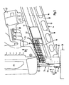
- Fig. 1 shows a schematic, partly cut-away side view of a preferred embodiment according to the present invention in a rest position;
- Fig. 2 shows the same view of the embodiment of figure 1 in an actuated operating position;
- Fig. 3 is a front view of a preferred embodiment of an attachment according to the present invention;
- Fig. 4 shows a cross-section of the attachment of figure 3 along the line A-A;
- Fig. 5 is a top view of the attachment of figure 3;
- Fig. 6 shows a bottom view of the attachment of figure 3 in combination with a schematic view of a magazine of a nail driving device.
- A first preferred embodiment (fig. 1) according to the present invention relates to a gas-firing hammer 1 comprising, among other parts,
housing 24 comprising a combustion engine and a fuel container, ahandle 26, abattery 27, atrigger 23. Such a device is per se known and the operation of these parts will not be described in detail in this text. The device further comprises a per se knownbarrel 3 with an actuator 25 which is arranged therealong and which debouches at the end of the barrel into an actuator head arranged round the barrel and having pointed tips which will for instance prevent shifting when the device is actuated. - The device further comprises a magazine 4 which is suitable for holding nails arranged in strips. These nails are arranged in the magazine such that the
heads 21 of the nails are situated in thehead guide channel 22. The shank of the nail, with the tip arranged on the other end relative to the head, extends from thehead guide channel 22 into the magazine. The length of the nail is herein such that it extends no further than thebottom edge 19 of the magazine. The shank herein extends betweenside walls 20 of the magazine, these side walls being provided withopenings 18 which on the one hand save weight and on the other provide a view into the magazine. Apressure slide 17 is further provided in the magazine for the purpose of pressing the strip and nails in the direction of the barrel. - Because of the presence of this slide 17 a relatively large part of the magazine is necessarily open at the position of this slide. The relatively
short nails 13 shown in the figure can hereby tilt transversely of the guide direction of the slide. In order to prevent this tilting of nails 13 afastening member 15 is mounted at the beginning of the slide, wherein aguide rod 16 extends in the guide direction of the magazine from this fastening member. This preferably takes place in the manner shown in figure 2, whereinguide rod 16 extends behind the slide. The slide is preferably held under bias by means of a flat spring which can be wound up. - According to the present invention an
attachment 2 is placed over the actuation member 25 present on the barrel and subsequently fixed inopening 7 by means of a screw element. A screw thread M6 is for instance applied here. The attachment comprises a substantially flattenedcircular wall 5 which is placed round the actuation member.Attachment 2 also comprises anend wall 6 having therein an opening which is shown in figure 1 in the line of the barrel. The attachment also comprises aflat plate 8 which extends partially through the substantiallycylindrical wall 5 on the side of the magazine when the attachment is placed on the device.Flat plate 8 has a "barrel wall" 10 which defines a part of the barrel of the gas-firing hammer. The shown relativelyshort nails 13 are hereby guided through the barrel, whereby there is no risk they will egress through the open side of the barrel suitable for allowing a long shank of the nail extending to a position close to the bottom edge ofmagazine 19. -
Flat plate 8 is further provided on the top side with apressing wall 11 which has an angle relative to the barrel such that it can press a number of, such as for instance the shown four nail tips, in the actuation position of the attachment as shown in figure 2. At each actuation of the device the strip with nails is hereby once again positioned as well as possible relative to the barrel. - Figure 1 shows the device in the passive state, wherein actuation unit 25, the
nail driving rod 12 and the attachment are situated in the rest position. In order to drive a nail into aworkpiece 28 the attachment and the actuation unit 25 are pressed upward relative to the barrel and the device in the direction of arrow C by pressing the gas-firing hammer downward in the direction of arrow A. Actuation unit 25, a pin of which extends along the barrel, is hereby driven into the device and the combustion engine is activated in per se known manner whentrigger 23 is also actuated. - The
nail driving rod 12 is then thrust downward by the combustion engine and pushes thenail 13 downward through the barrel. Through actuation ofattachment 2 thepressing wall 11 ofplate 8 of the attachment is pressed against the nail array, whereby the foremost nail situated in the barrel is oriented as well as possible just before thenail driving rod 12 tears it from the strip and drives it intoworkpiece 28. During this driving operation the nail is guided downward by the barrel and also byguide wall 10 ofplate 8 in appropriate manner through the barrel and eventually throughopening 9 on the underside ofend plate 6 of the attachment. - The attachment is shown in greater detail in figures 3-6. Figure 6 shows a bottom view of the attachment wherein the two side walls of the magazine are shown as they extend on either side along
plate 8 in the position of use of the attachment. The outer ends ofside walls 20 of the magazine are shown with broken lines since in bottom view they have to be situated above the shown position of the attachment. - The walls of the magazine are provided for this purpose with a recess or
opening 29. The shanks of long nails are hereby situated partially in this free space as they approach the open side of the barrel. Because such long nails are also guided through a higher part of the magazine, such long nails will hereby remain oriented in the lengthwise direction. - The open side of the barrel results in a further advantage of the present invention. By applying the attachment on such a long barrel open on the side there is the advantage that a possible disruption during the feed and/or throughfeed of short nails in particular can be obviated in simple manner in that, because of the presence of much free space due to, among other things, the
opening 29 in the magazine, the disruption can be remedied using the fingers and/or with a tool. Certainly when the attachment is removed there is, owing to such an arrangement, much space available for gaining access to the barrel. Such a significant advantage is not possible in a gas-firing hammer specifically suitable for the short tacks or 'haften' nails, among other reasons because there is very little space available in such a relatively short barrel. - A further advantage of the shown embodiment is that the wall of the attachment is flattened on two sides, whereby the distance of the nail to be inserted relative to the outer side of the wall is relatively small. Nails can hereby be inserted closely against a standing edge or wall. The same flattened wall can be envisaged on the front side of the attachment or for instance at any conceivable angle along the periphery of the wall subject to the application of the gas-firing hammer. The strength of the hereby weakened side wall can be obtained by the end plate and/or thickened portions in other parts of the attachment.
- The present invention is described in the foregoing on the basis of several preferred embodiments. The described device is for instance described on the basis of nails with a round head and at a determined angle. The invention is not limited hereto and can likewise be applied with nails having a D-shaped head and at any random angle. The invention is also described on the basis of a gas-firing hammer. The invention is however also suitable for a device with a powder-firing hammer or a device driven for instance by air pressure or an electric motor.
- The invention includes an attachment for a fastener gun having a barrel along which fasteners are fired and a magazine for holding fasteners having a first length and from which said first length fasteners are fed one by one into said barrel, said attachment being releasably securable to said nail gun and including a stop surface arranged such that when, in use, the attachment is secured to a said nail gun and the magazine of the nail gun is holding fasteners having a second length that is shorter than said first length, the stop surface is positioned to restrict movement in the firing direction of the fastener gun of at least the fastener in the magazine that is positioned to be next fed into the barrel.
- Preferably the nail gun comprises an actuator member slidable on said barrel and the attachment is releasably securable to the actuator member.
- Different aspects of different embodiments are deemed described in combination thereof, wherein all combinations which can be made on the basis of this document by a skilled person must be included. These preferred embodiments are not limitative for the scope of protection of this text. The rights sought are defined in the appended claims.
Claims (12)
- Nail driving device for driving into an object at least a first relatively long type of nail and a second relatively short type of nail, comprising:- a drive unit for driving a thrust or pushing member for driving the nail into the object,- a magazine for holding a supply of nails preferably arranged in an array,- a barrel for driving a nail therethrough in the longitudinal direction thereof during driving of the nail into the object, wherein the barrel comprises a side inlet for the first and second type of nail,- an actuator for actuating the driving operation, and- an attachment for facilitating driving of the second relatively short type of nail into the object.
- Nail driving device as claimed in claim 1, wherein the attachment can be mounted on an actuator for the driving-in process arranged on the barrel and/or can be mounted in releasable manner on the nail driving device.
- Nail driving device as claimed in claim 1 or 2, wherein the attachment comprises a guide member which, in the position of the attachment mounted on the barrel, provides a guiding for the short type of nail.
- Nail driving device as claimed in one or more of the foregoing claims, wherein the attachment comprises a substantially protective actuation end part for protecting the object upon actuation of the driving-in process.
- Nail driving device as claimed in one or more of the foregoing claims, wherein the attachment comprises a positioning member for positioning at least some of the nails arranged in the array during the actuation for the purpose of providing a suitable orientation relative to the barrel.
- Nail driving device as claimed in claim 5, wherein the positioning member comprises a pressing end part which extends in the direction of the magazine at an angle to the barrel substantially corresponding to the angle of the magazine relative to the barrel.
- Nail driving device as claimed in one or more of the foregoing claims, wherein the magazine is adapted to guide at least the outer ends of both the first and the second type of nails.
- Nail driving device as claimed in claim 7, wherein the magazine is provided with one or two guides for preventing tilting of the short nails in a direction which differs from the feed direction of the magazine.
- Nail driving device as claimed in one or more of the foregoing claims, wherein the attachment is embodied comprising:- a substantially cylindrical or flattened cylindrical basic body,- a mounting member for mounting on the nail driving device,- a substantially flat end surface with a passage opening for nails, this passage opening lying in line with the barrel in the position of use of the attachment, and- a substantially plate-like or flat member which serves as positioning member.
- Nail driving device as claimed in one or more of the claims 1-9, wherein the attachment comprises one or more flattened portions in a side wall thereof.
- Attachment for a nail driving device as claimed in one or more of the foregoing claims.
- Method for driving in nails, comprising steps for the use of the nail driving device and/or an attachment as claimed in one or more of the foregoing claims.
Applications Claiming Priority (1)
| Application Number | Priority Date | Filing Date | Title |
|---|---|---|---|
| NL1032352A NL1032352C2 (en) | 2006-08-22 | 2006-08-22 | Nail drive device, attachment therefor and method. |
Publications (3)
| Publication Number | Publication Date |
|---|---|
| EP1892061A1 true EP1892061A1 (en) | 2008-02-27 |
| EP1892061B1 EP1892061B1 (en) | 2012-08-01 |
| EP1892061B8 EP1892061B8 (en) | 2012-09-05 |
Family
ID=37708173
Family Applications (1)
| Application Number | Title | Priority Date | Filing Date |
|---|---|---|---|
| EP20070016316 Not-in-force EP1892061B8 (en) | 2006-08-22 | 2007-08-21 | Nail driving device, attachment therefor and method |
Country Status (2)
| Country | Link |
|---|---|
| EP (1) | EP1892061B8 (en) |
| NL (1) | NL1032352C2 (en) |
Cited By (3)
| Publication number | Priority date | Publication date | Assignee | Title |
|---|---|---|---|---|
| WO2012065090A1 (en) * | 2010-11-12 | 2012-05-18 | Illinois Tool Works Inc. | Fastener -driving tool |
| CN104227659A (en) * | 2013-06-21 | 2014-12-24 | 苏州宝时得电动工具有限公司 | Electric hammer with nail box |
| US10493607B2 (en) | 2016-06-28 | 2019-12-03 | Black & Decker, Inc. | Concrete nailer having magazine cutout for deep tracks |
Citations (3)
| Publication number | Priority date | Publication date | Assignee | Title |
|---|---|---|---|---|
| US5437404A (en) | 1993-07-13 | 1995-08-01 | Illinois Tool Works Inc. | Adjustable shear block assembly |
| US5615819A (en) * | 1995-10-03 | 1997-04-01 | Hou; Chang Feng-Mei | Nail magazine structure of a power nailer |
| US6896165B1 (en) * | 2004-03-22 | 2005-05-24 | Bentley Fastening Tools Co., Ltd. | Device for preventing short nails of a nail gun from being deadlocked |
-
2006
- 2006-08-22 NL NL1032352A patent/NL1032352C2/en not_active IP Right Cessation
-
2007
- 2007-08-21 EP EP20070016316 patent/EP1892061B8/en not_active Not-in-force
Patent Citations (3)
| Publication number | Priority date | Publication date | Assignee | Title |
|---|---|---|---|---|
| US5437404A (en) | 1993-07-13 | 1995-08-01 | Illinois Tool Works Inc. | Adjustable shear block assembly |
| US5615819A (en) * | 1995-10-03 | 1997-04-01 | Hou; Chang Feng-Mei | Nail magazine structure of a power nailer |
| US6896165B1 (en) * | 2004-03-22 | 2005-05-24 | Bentley Fastening Tools Co., Ltd. | Device for preventing short nails of a nail gun from being deadlocked |
Cited By (4)
| Publication number | Priority date | Publication date | Assignee | Title |
|---|---|---|---|---|
| WO2012065090A1 (en) * | 2010-11-12 | 2012-05-18 | Illinois Tool Works Inc. | Fastener -driving tool |
| CN104227659A (en) * | 2013-06-21 | 2014-12-24 | 苏州宝时得电动工具有限公司 | Electric hammer with nail box |
| CN104227659B (en) * | 2013-06-21 | 2016-11-23 | 苏州宝时得电动工具有限公司 | Electric hammer with staple cartridge |
| US10493607B2 (en) | 2016-06-28 | 2019-12-03 | Black & Decker, Inc. | Concrete nailer having magazine cutout for deep tracks |
Also Published As
| Publication number | Publication date |
|---|---|
| NL1032352C2 (en) | 2008-02-25 |
| EP1892061B8 (en) | 2012-09-05 |
| EP1892061B1 (en) | 2012-08-01 |
Similar Documents
| Publication | Publication Date | Title |
|---|---|---|
| US4380312A (en) | Stapling tool | |
| CA2422447C (en) | Framing tool with automatic fastener-size adjustment | |
| US8627991B2 (en) | Fastening tool with blind guide work contact tip | |
| US6679414B2 (en) | Interchangeable magazine for a tool | |
| EP1951478B1 (en) | Combustion-powered driving tool with workpiece contact element | |
| US7506789B2 (en) | Continuous feed cap system | |
| US6032848A (en) | Fastener-driving tool having wear guard defining fastener-guiding surface | |
| JPH0624719B2 (en) | Fastener driving tool | |
| US5437404A (en) | Adjustable shear block assembly | |
| KR20070114275A (en) | Power nailer with driver blade blocking mechanism in magazine | |
| WO2014182463A1 (en) | Fastening device for driving double-headed fasteners | |
| EP1892061A1 (en) | Nail driving device, attachment therfore and method | |
| US10688640B2 (en) | Magazine for a fastener tool | |
| US20050050712A1 (en) | Fastener driving tool for spacing object from substrate | |
| US6123245A (en) | Nailer with nail guiding channel | |
| JP5218330B2 (en) | Impact tool | |
| US20200376639A1 (en) | Multiple strike fastener driver/holder | |
| US11338423B2 (en) | Slap hammer with cap dispenser | |
| US4643345A (en) | Combination staple and riveting gun | |
| EP1880805A1 (en) | Cap nailer and feed system | |
| US20040182908A1 (en) | Power tool for metal piercing fasteners | |
| JP3117696U (en) | Nail clogging tool for nailing machine | |
| EP1880807A1 (en) | Cap bypass feeder | |
| US20080017685A1 (en) | Cap collation system | |
| WO1994021430A1 (en) | Portable fastener driver assembly |
Legal Events
| Date | Code | Title | Description |
|---|---|---|---|
| PUAI | Public reference made under article 153(3) epc to a published international application that has entered the european phase |
Free format text: ORIGINAL CODE: 0009012 |
|
| AK | Designated contracting states |
Kind code of ref document: A1 Designated state(s): AT BE BG CH CY CZ DE DK EE ES FI FR GB GR HU IE IS IT LI LT LU LV MC MT NL PL PT RO SE SI SK TR |
|
| AX | Request for extension of the european patent |
Extension state: AL BA HR MK YU |
|
| 17P | Request for examination filed |
Effective date: 20080827 |
|
| AKX | Designation fees paid |
Designated state(s): AT BE CH DE LI NL |
|
| R17P | Request for examination filed (corrected) |
Effective date: 20080827 |
|
| RBV | Designated contracting states (corrected) |
Designated state(s): AT BE BG CH CY CZ DE DK EE ES FI FR GB GR HU IE IS IT LI LT LU LV MC MT NL PL PT RO SE SI SK TR |
|
| RTI1 | Title (correction) |
Free format text: NAIL DRIVING DEVICE, ATTACHMENT THEREFOR AND METHOD |
|
| GRAP | Despatch of communication of intention to grant a patent |
Free format text: ORIGINAL CODE: EPIDOSNIGR1 |
|
| GRAS | Grant fee paid |
Free format text: ORIGINAL CODE: EPIDOSNIGR3 |
|
| GRAA | (expected) grant |
Free format text: ORIGINAL CODE: 0009210 |
|
| AK | Designated contracting states |
Kind code of ref document: B1 Designated state(s): AT BE BG CH CY CZ DE DK EE ES FI FR GB GR HU IE IS IT LI LT LU LV MC MT NL PL PT RO SE SI SK TR |
|
| REG | Reference to a national code |
Ref country code: GB Ref legal event code: FG4D |
|
| REG | Reference to a national code |
Ref country code: AT Ref legal event code: REF Ref document number: 568408 Country of ref document: AT Kind code of ref document: T Effective date: 20120815 Ref country code: CH Ref legal event code: EP |
|
| RAP2 | Party data changed (patent owner data changed or rights of a patent transferred) |
Owner name: BLACK & DECKER INC. |
|
| REG | Reference to a national code |
Ref country code: IE Ref legal event code: FG4D |
|
| REG | Reference to a national code |
Ref country code: DE Ref legal event code: R096 Ref document number: 602007024264 Country of ref document: DE Effective date: 20120927 |
|
| REG | Reference to a national code |
Ref country code: NL Ref legal event code: T3 |
|
| REG | Reference to a national code |
Ref country code: LT Ref legal event code: MG4D Effective date: 20120801 |
|
| PG25 | Lapsed in a contracting state [announced via postgrant information from national office to epo] |
Ref country code: LT Free format text: LAPSE BECAUSE OF FAILURE TO SUBMIT A TRANSLATION OF THE DESCRIPTION OR TO PAY THE FEE WITHIN THE PRESCRIBED TIME-LIMIT Effective date: 20120801 Ref country code: IS Free format text: LAPSE BECAUSE OF FAILURE TO SUBMIT A TRANSLATION OF THE DESCRIPTION OR TO PAY THE FEE WITHIN THE PRESCRIBED TIME-LIMIT Effective date: 20121201 Ref country code: FI Free format text: LAPSE BECAUSE OF FAILURE TO SUBMIT A TRANSLATION OF THE DESCRIPTION OR TO PAY THE FEE WITHIN THE PRESCRIBED TIME-LIMIT Effective date: 20120801 Ref country code: CY Free format text: LAPSE BECAUSE OF FAILURE TO SUBMIT A TRANSLATION OF THE DESCRIPTION OR TO PAY THE FEE WITHIN THE PRESCRIBED TIME-LIMIT Effective date: 20120801 |
|
| PG25 | Lapsed in a contracting state [announced via postgrant information from national office to epo] |
Ref country code: SI Free format text: LAPSE BECAUSE OF FAILURE TO SUBMIT A TRANSLATION OF THE DESCRIPTION OR TO PAY THE FEE WITHIN THE PRESCRIBED TIME-LIMIT Effective date: 20120801 Ref country code: PT Free format text: LAPSE BECAUSE OF FAILURE TO SUBMIT A TRANSLATION OF THE DESCRIPTION OR TO PAY THE FEE WITHIN THE PRESCRIBED TIME-LIMIT Effective date: 20121203 Ref country code: SE Free format text: LAPSE BECAUSE OF FAILURE TO SUBMIT A TRANSLATION OF THE DESCRIPTION OR TO PAY THE FEE WITHIN THE PRESCRIBED TIME-LIMIT Effective date: 20120801 Ref country code: PL Free format text: LAPSE BECAUSE OF FAILURE TO SUBMIT A TRANSLATION OF THE DESCRIPTION OR TO PAY THE FEE WITHIN THE PRESCRIBED TIME-LIMIT Effective date: 20120801 Ref country code: GR Free format text: LAPSE BECAUSE OF FAILURE TO SUBMIT A TRANSLATION OF THE DESCRIPTION OR TO PAY THE FEE WITHIN THE PRESCRIBED TIME-LIMIT Effective date: 20121102 Ref country code: LV Free format text: LAPSE BECAUSE OF FAILURE TO SUBMIT A TRANSLATION OF THE DESCRIPTION OR TO PAY THE FEE WITHIN THE PRESCRIBED TIME-LIMIT Effective date: 20120801 |
|
| PG25 | Lapsed in a contracting state [announced via postgrant information from national office to epo] |
Ref country code: MC Free format text: LAPSE BECAUSE OF NON-PAYMENT OF DUE FEES Effective date: 20120831 |
|
| PG25 | Lapsed in a contracting state [announced via postgrant information from national office to epo] |
Ref country code: RO Free format text: LAPSE BECAUSE OF FAILURE TO SUBMIT A TRANSLATION OF THE DESCRIPTION OR TO PAY THE FEE WITHIN THE PRESCRIBED TIME-LIMIT Effective date: 20120801 Ref country code: CZ Free format text: LAPSE BECAUSE OF FAILURE TO SUBMIT A TRANSLATION OF THE DESCRIPTION OR TO PAY THE FEE WITHIN THE PRESCRIBED TIME-LIMIT Effective date: 20120801 Ref country code: DK Free format text: LAPSE BECAUSE OF FAILURE TO SUBMIT A TRANSLATION OF THE DESCRIPTION OR TO PAY THE FEE WITHIN THE PRESCRIBED TIME-LIMIT Effective date: 20120801 Ref country code: ES Free format text: LAPSE BECAUSE OF FAILURE TO SUBMIT A TRANSLATION OF THE DESCRIPTION OR TO PAY THE FEE WITHIN THE PRESCRIBED TIME-LIMIT Effective date: 20121112 Ref country code: EE Free format text: LAPSE BECAUSE OF FAILURE TO SUBMIT A TRANSLATION OF THE DESCRIPTION OR TO PAY THE FEE WITHIN THE PRESCRIBED TIME-LIMIT Effective date: 20120801 |
|
| REG | Reference to a national code |
Ref country code: IE Ref legal event code: MM4A |
|
| PG25 | Lapsed in a contracting state [announced via postgrant information from national office to epo] |
Ref country code: IT Free format text: LAPSE BECAUSE OF FAILURE TO SUBMIT A TRANSLATION OF THE DESCRIPTION OR TO PAY THE FEE WITHIN THE PRESCRIBED TIME-LIMIT Effective date: 20120801 Ref country code: SK Free format text: LAPSE BECAUSE OF FAILURE TO SUBMIT A TRANSLATION OF THE DESCRIPTION OR TO PAY THE FEE WITHIN THE PRESCRIBED TIME-LIMIT Effective date: 20120801 |
|
| PLBE | No opposition filed within time limit |
Free format text: ORIGINAL CODE: 0009261 |
|
| STAA | Information on the status of an ep patent application or granted ep patent |
Free format text: STATUS: NO OPPOSITION FILED WITHIN TIME LIMIT |
|
| 26N | No opposition filed |
Effective date: 20130503 |
|
| PG25 | Lapsed in a contracting state [announced via postgrant information from national office to epo] |
Ref country code: IE Free format text: LAPSE BECAUSE OF NON-PAYMENT OF DUE FEES Effective date: 20120821 Ref country code: BG Free format text: LAPSE BECAUSE OF FAILURE TO SUBMIT A TRANSLATION OF THE DESCRIPTION OR TO PAY THE FEE WITHIN THE PRESCRIBED TIME-LIMIT Effective date: 20121101 |
|
| REG | Reference to a national code |
Ref country code: DE Ref legal event code: R097 Ref document number: 602007024264 Country of ref document: DE Effective date: 20130503 |
|
| PG25 | Lapsed in a contracting state [announced via postgrant information from national office to epo] |
Ref country code: MT Free format text: LAPSE BECAUSE OF FAILURE TO SUBMIT A TRANSLATION OF THE DESCRIPTION OR TO PAY THE FEE WITHIN THE PRESCRIBED TIME-LIMIT Effective date: 20120801 |
|
| PG25 | Lapsed in a contracting state [announced via postgrant information from national office to epo] |
Ref country code: TR Free format text: LAPSE BECAUSE OF FAILURE TO SUBMIT A TRANSLATION OF THE DESCRIPTION OR TO PAY THE FEE WITHIN THE PRESCRIBED TIME-LIMIT Effective date: 20120801 |
|
| PG25 | Lapsed in a contracting state [announced via postgrant information from national office to epo] |
Ref country code: LU Free format text: LAPSE BECAUSE OF NON-PAYMENT OF DUE FEES Effective date: 20120821 |
|
| PG25 | Lapsed in a contracting state [announced via postgrant information from national office to epo] |
Ref country code: HU Free format text: LAPSE BECAUSE OF FAILURE TO SUBMIT A TRANSLATION OF THE DESCRIPTION OR TO PAY THE FEE WITHIN THE PRESCRIBED TIME-LIMIT Effective date: 20070821 |
|
| REG | Reference to a national code |
Ref country code: FR Ref legal event code: PLFP Year of fee payment: 10 |
|
| REG | Reference to a national code |
Ref country code: FR Ref legal event code: PLFP Year of fee payment: 11 |
|
| PGFP | Annual fee paid to national office [announced via postgrant information from national office to epo] |
Ref country code: NL Payment date: 20170814 Year of fee payment: 11 |
|
| PGFP | Annual fee paid to national office [announced via postgrant information from national office to epo] |
Ref country code: GB Payment date: 20170719 Year of fee payment: 11 Ref country code: GB Payment date: 20170816 Year of fee payment: 11 Ref country code: CH Payment date: 20170814 Year of fee payment: 11 |
|
| PGFP | Annual fee paid to national office [announced via postgrant information from national office to epo] |
Ref country code: AT Payment date: 20170725 Year of fee payment: 11 |
|
| REG | Reference to a national code |
Ref country code: FR Ref legal event code: PLFP Year of fee payment: 12 |
|
| PGFP | Annual fee paid to national office [announced via postgrant information from national office to epo] |
Ref country code: BE Payment date: 20180614 Year of fee payment: 12 |
|
| PGFP | Annual fee paid to national office [announced via postgrant information from national office to epo] |
Ref country code: FR Payment date: 20180712 Year of fee payment: 12 |
|
| REG | Reference to a national code |
Ref country code: DE Ref legal event code: R119 Ref document number: 602007024264 Country of ref document: DE |
|
| REG | Reference to a national code |
Ref country code: CH Ref legal event code: PL |
|
| REG | Reference to a national code |
Ref country code: NL Ref legal event code: MM Effective date: 20180901 |
|
| REG | Reference to a national code |
Ref country code: AT Ref legal event code: MM01 Ref document number: 568408 Country of ref document: AT Kind code of ref document: T Effective date: 20180821 |
|
| GBPC | Gb: european patent ceased through non-payment of renewal fee |
Effective date: 20180821 |
|
| PG25 | Lapsed in a contracting state [announced via postgrant information from national office to epo] |
Ref country code: AT Free format text: LAPSE BECAUSE OF NON-PAYMENT OF DUE FEES Effective date: 20180821 Ref country code: LI Free format text: LAPSE BECAUSE OF NON-PAYMENT OF DUE FEES Effective date: 20180831 Ref country code: CH Free format text: LAPSE BECAUSE OF NON-PAYMENT OF DUE FEES Effective date: 20180831 |
|
| PG25 | Lapsed in a contracting state [announced via postgrant information from national office to epo] |
Ref country code: NL Free format text: LAPSE BECAUSE OF NON-PAYMENT OF DUE FEES Effective date: 20180901 |
|
| PG25 | Lapsed in a contracting state [announced via postgrant information from national office to epo] |
Ref country code: DE Free format text: LAPSE BECAUSE OF NON-PAYMENT OF DUE FEES Effective date: 20190301 |
|
| PG25 | Lapsed in a contracting state [announced via postgrant information from national office to epo] |
Ref country code: GB Free format text: LAPSE BECAUSE OF NON-PAYMENT OF DUE FEES Effective date: 20180821 |
|
| REG | Reference to a national code |
Ref country code: BE Ref legal event code: MM Effective date: 20190831 |
|
| PG25 | Lapsed in a contracting state [announced via postgrant information from national office to epo] |
Ref country code: FR Free format text: LAPSE BECAUSE OF NON-PAYMENT OF DUE FEES Effective date: 20190831 |
|
| PG25 | Lapsed in a contracting state [announced via postgrant information from national office to epo] |
Ref country code: BE Free format text: LAPSE BECAUSE OF NON-PAYMENT OF DUE FEES Effective date: 20190831 |