EP1892029A1 - Permeable member, permeable member kit, and permeable casing and permeable tank using them - Google Patents
Permeable member, permeable member kit, and permeable casing and permeable tank using them Download PDFInfo
- Publication number
- EP1892029A1 EP1892029A1 EP06756942A EP06756942A EP1892029A1 EP 1892029 A1 EP1892029 A1 EP 1892029A1 EP 06756942 A EP06756942 A EP 06756942A EP 06756942 A EP06756942 A EP 06756942A EP 1892029 A1 EP1892029 A1 EP 1892029A1
- Authority
- EP
- European Patent Office
- Prior art keywords
- ventilation member
- gas permeable
- permeable membrane
- gas
- absorbing layer
- Prior art date
- Legal status (The legal status is an assumption and is not a legal conclusion. Google has not performed a legal analysis and makes no representation as to the accuracy of the status listed.)
- Granted
Links
Images


Classifications
-
- F—MECHANICAL ENGINEERING; LIGHTING; HEATING; WEAPONS; BLASTING
- F16—ENGINEERING ELEMENTS AND UNITS; GENERAL MEASURES FOR PRODUCING AND MAINTAINING EFFECTIVE FUNCTIONING OF MACHINES OR INSTALLATIONS; THERMAL INSULATION IN GENERAL
- F16K—VALVES; TAPS; COCKS; ACTUATING-FLOATS; DEVICES FOR VENTING OR AERATING
- F16K15/00—Check valves
- F16K15/14—Check valves with flexible valve members
- F16K15/144—Check valves with flexible valve members the closure elements being fixed along all or a part of their periphery
- F16K15/145—Check valves with flexible valve members the closure elements being fixed along all or a part of their periphery the closure elements being shaped as a solids of revolution, e.g. cylindrical or conical
-
- B—PERFORMING OPERATIONS; TRANSPORTING
- B01—PHYSICAL OR CHEMICAL PROCESSES OR APPARATUS IN GENERAL
- B01D—SEPARATION
- B01D53/00—Separation of gases or vapours; Recovering vapours of volatile solvents from gases; Chemical or biological purification of waste gases, e.g. engine exhaust gases, smoke, fumes, flue gases, aerosols
- B01D53/26—Drying gases or vapours
- B01D53/263—Drying gases or vapours by absorption
-
- B—PERFORMING OPERATIONS; TRANSPORTING
- B01—PHYSICAL OR CHEMICAL PROCESSES OR APPARATUS IN GENERAL
- B01D—SEPARATION
- B01D53/00—Separation of gases or vapours; Recovering vapours of volatile solvents from gases; Chemical or biological purification of waste gases, e.g. engine exhaust gases, smoke, fumes, flue gases, aerosols
- B01D53/26—Drying gases or vapours
- B01D53/261—Drying gases or vapours by adsorption
-
- B—PERFORMING OPERATIONS; TRANSPORTING
- B01—PHYSICAL OR CHEMICAL PROCESSES OR APPARATUS IN GENERAL
- B01D—SEPARATION
- B01D53/00—Separation of gases or vapours; Recovering vapours of volatile solvents from gases; Chemical or biological purification of waste gases, e.g. engine exhaust gases, smoke, fumes, flue gases, aerosols
- B01D53/26—Drying gases or vapours
- B01D53/28—Selection of materials for use as drying agents
-
- B—PERFORMING OPERATIONS; TRANSPORTING
- B60—VEHICLES IN GENERAL
- B60R—VEHICLES, VEHICLE FITTINGS, OR VEHICLE PARTS, NOT OTHERWISE PROVIDED FOR
- B60R16/00—Electric or fluid circuits specially adapted for vehicles and not otherwise provided for; Arrangement of elements of electric or fluid circuits specially adapted for vehicles and not otherwise provided for
- B60R16/02—Electric or fluid circuits specially adapted for vehicles and not otherwise provided for; Arrangement of elements of electric or fluid circuits specially adapted for vehicles and not otherwise provided for electric constitutive elements
-
- F—MECHANICAL ENGINEERING; LIGHTING; HEATING; WEAPONS; BLASTING
- F16—ENGINEERING ELEMENTS AND UNITS; GENERAL MEASURES FOR PRODUCING AND MAINTAINING EFFECTIVE FUNCTIONING OF MACHINES OR INSTALLATIONS; THERMAL INSULATION IN GENERAL
- F16K—VALVES; TAPS; COCKS; ACTUATING-FLOATS; DEVICES FOR VENTING OR AERATING
- F16K15/00—Check valves
- F16K15/14—Check valves with flexible valve members
- F16K15/148—Check valves with flexible valve members the closure elements being fixed in their centre
-
- F—MECHANICAL ENGINEERING; LIGHTING; HEATING; WEAPONS; BLASTING
- F16—ENGINEERING ELEMENTS AND UNITS; GENERAL MEASURES FOR PRODUCING AND MAINTAINING EFFECTIVE FUNCTIONING OF MACHINES OR INSTALLATIONS; THERMAL INSULATION IN GENERAL
- F16K—VALVES; TAPS; COCKS; ACTUATING-FLOATS; DEVICES FOR VENTING OR AERATING
- F16K24/00—Devices, e.g. valves, for venting or aerating enclosures
-
- F—MECHANICAL ENGINEERING; LIGHTING; HEATING; WEAPONS; BLASTING
- F21—LIGHTING
- F21S—NON-PORTABLE LIGHTING DEVICES; SYSTEMS THEREOF; VEHICLE LIGHTING DEVICES SPECIALLY ADAPTED FOR VEHICLE EXTERIORS
- F21S45/00—Arrangements within vehicle lighting devices specially adapted for vehicle exteriors, for purposes other than emission or distribution of light
- F21S45/30—Ventilation or drainage of lighting devices
-
- F—MECHANICAL ENGINEERING; LIGHTING; HEATING; WEAPONS; BLASTING
- F21—LIGHTING
- F21V—FUNCTIONAL FEATURES OR DETAILS OF LIGHTING DEVICES OR SYSTEMS THEREOF; STRUCTURAL COMBINATIONS OF LIGHTING DEVICES WITH OTHER ARTICLES, NOT OTHERWISE PROVIDED FOR
- F21V31/00—Gas-tight or water-tight arrangements
- F21V31/03—Gas-tight or water-tight arrangements with provision for venting
-
- H—ELECTRICITY
- H05—ELECTRIC TECHNIQUES NOT OTHERWISE PROVIDED FOR
- H05K—PRINTED CIRCUITS; CASINGS OR CONSTRUCTIONAL DETAILS OF ELECTRIC APPARATUS; MANUFACTURE OF ASSEMBLAGES OF ELECTRICAL COMPONENTS
- H05K5/00—Casings, cabinets or drawers for electric apparatus
- H05K5/02—Details
- H05K5/0213—Venting apertures; Constructional details thereof
- H05K5/0216—Venting plugs comprising semi-permeable membranes
-
- Y—GENERAL TAGGING OF NEW TECHNOLOGICAL DEVELOPMENTS; GENERAL TAGGING OF CROSS-SECTIONAL TECHNOLOGIES SPANNING OVER SEVERAL SECTIONS OF THE IPC; TECHNICAL SUBJECTS COVERED BY FORMER USPC CROSS-REFERENCE ART COLLECTIONS [XRACs] AND DIGESTS
- Y10—TECHNICAL SUBJECTS COVERED BY FORMER USPC
- Y10T—TECHNICAL SUBJECTS COVERED BY FORMER US CLASSIFICATION
- Y10T137/00—Fluid handling
- Y10T137/7722—Line condition change responsive valves
- Y10T137/7837—Direct response valves [i.e., check valve type]
- Y10T137/7838—Plural
-
- Y—GENERAL TAGGING OF NEW TECHNOLOGICAL DEVELOPMENTS; GENERAL TAGGING OF CROSS-SECTIONAL TECHNOLOGIES SPANNING OVER SEVERAL SECTIONS OF THE IPC; TECHNICAL SUBJECTS COVERED BY FORMER USPC CROSS-REFERENCE ART COLLECTIONS [XRACs] AND DIGESTS
- Y10—TECHNICAL SUBJECTS COVERED BY FORMER USPC
- Y10T—TECHNICAL SUBJECTS COVERED BY FORMER US CLASSIFICATION
- Y10T137/00—Fluid handling
- Y10T137/7722—Line condition change responsive valves
- Y10T137/7837—Direct response valves [i.e., check valve type]
- Y10T137/7879—Resilient material valve
- Y10T137/788—Having expansible port
- Y10T137/7882—Having exit lip
Definitions
- the present invention relates to a ventilation member and a ventilation member kit that are fixed to a tank, or to a housing for electrical components (typically automobile electrical components) for ensuring ventilation between the interior and the exterior of the tank or the housing and suppressing the entry of foreign matter into the interior of the tank or the housing.
- the invention also relates to a vented housing and a vented tank in which the ventilation member and/or the ventilation member kit is/are fixed.
- ventilation members are attached to housings of electric appliances such as mobile telephones, cameras, and of automobile electrical components including lamps, pressure sensors, and ECUs (Electrical Control Units), in order to ensure ventilation between the interior and the exterior of the housings and to prevent the entry of foreign matter into the interior of the housings.
- Attaching such ventilation members to the housings makes it possible to prevent the entry of water, dust, and the like into the interior of the housings and at the same time to achieve the following; the pressure change inside the housing associated with temperature change can be alleviated, sound can be transmitted between the interior and the exterior of the housing, and the gas produced in the interior of the housing can be discharged to the exterior of the housing.
- a ventilation member 101 disclosed in Document 1 has, as shown in Fig. 16 , a tubular support body 103 and a closed-bottomed protective cover 104.
- a gas permeable membrane 102 is disposed on one end face of the tubular support body 103.
- the protective cover 104 is fitted to the support body 103 so as to cover the gas permeable membrane 102.
- the ventilation member 101 is fixed to a housing 105 so as to cover an opening 106 of the housing 105, and gas is allowed to permeate through the gas permeable membrane 102 so that ventilation between the interior and the exterior of the housing 105 is ensured.
- the protective cover 104 is provided in order to prevent the breakage of the gas permeable membrane 102 caused by, for example, contact with foreign objects.
- the conventional ventilation member 101 allows the gas inside the housing 105 and the gas outside the housing 105 to be in communication with each other via the gas permeable membrane 102 at all times, and therefore, water vapor outside the housing 105 may enter the interior of the housing 105, producing water droplets on the inner surface of the housing 105 (i.e., fogging the inner surface of the housing 105).
- the housing is a lamp that is one type of automobile electrical components
- the water droplets can become a cause of reducing the light intensity of the light emitted from the lamp.
- fogging is apt to occur by turning off the lamp when the air temperature is low and the humidity of the exterior the housing is high (for example, when it is raining or snowing in winter).
- a conventional ventilation member is attached to a tank (such as a bottle for chemicals, an organic solvent tank, and a gas tank), it is possible to obtain similar advantageous effects to those in the case where the ventilation member is attached to the housing, while preventing the entry of water, dust, and the like into the tank.
- a tank such as a bottle for chemicals, an organic solvent tank, and a gas tank
- the conventional ventilation member 101 when the conventional ventilation member 101 is attached to a tank, the gas inside the tank and the gas outside the tank are in communication with each other via the gas permeable membrane 102 at all times, as in the case where the conventional ventilation member 101 is attached to the housing 105. Consequently, water vapor outside the tank may enter the interior of the tank, causing adverse effects on the liquid accommodated in the tank or causing moisture to accumulate in the tank.
- a ventilation member includes: a first gas permeable membrane, a second gas permeable membrane, and an absorbing layer allowing a gas passing through an opening of a housing or a tank to permeate therethrough, with the ventilation member being fixed to the opening; a support body for supporting the first gas permeable membrane, the second gas permeable membrane, and the absorbing layer; and a first one-way valve disposed so as to cover the first gas permeable membrane.
- the first gas permeable membrane and the second gas permeable membrane are disposed in such a manner that the gas permeates through the gas permeable membranes independently of each other.
- the second gas permeable membrane and the absorbing layer are disposed in such a manner that the gas permeates through the second gas permeable membrane and the absorbing layer successively.
- the absorbing layer contains a water absorbent.
- a ventilation member kit includes: a first ventilation member comprising a first gas permeable membrane allowing a gas passing through a first opening of a housing or a tank to permeate therethrough, with the first ventilation member being fixed to the first opening, a first support body for supporting the first gas permeable membrane, and a first one-way valve disposed so as to cover the first gas permeable membrane; and a second ventilation member comprising a second gas permeable membrane and an absorbing layer allowing a gas passing through a second opening of the housing or the tank to permeate therethrough, with the second ventilation member being fixed to the second opening, and a second support body for supporting the second gas permeable membrane and the absorbing layer, wherein in the second ventilation member, the second gas permeable membrane and the absorbing layer are disposed in such a manner that the gas permeates through the second gas permeable membrane and the absorbing layer successively, and the absorbing layer contains a water absorbent.
- a vented housing according to the present invention is a vented housing having an opening for allowing gas to pass therethrough, and includes the foregoing ventilation member according to the present invention.
- the ventilation member is fixed to the opening in such a manner that a gas flow direction of the first one-way valve of the ventilation member is a direction in which the gas passes from an interior to an exterior of the housing.
- a vented housing according to the present invention is a vented housing having first and second openings for allowing gas to pass therethrough, and includes the foregoing ventilation member kit according to the present invention.
- the first ventilation member of the ventilation member kit is fixed to the first opening in such a manner that a gas flow direction of the first one-way valve of the first ventilation member is a direction in which the gas passes from an interior to an exterior of the housing.
- the second ventilation member of the ventilation member kit is fixed to the second opening.
- a vented tank according to the present invention is a vented tank having an opening for allowing gas to pass therethrough, and includes the foregoing ventilation member according to the present invention.
- the ventilation member is fixed to the opening in such a manner that a gas flow direction of the first one-way valve of the ventilation member is a direction in which the gas passes from an interior to an exterior of the tank.
- a vented tank according to the present invention is a vented tank having first and second openings for allowing gas to pass therethrough, and includes the foregoing ventilation member kit according to the present invention.
- the first ventilation member of the ventilation member kit is fixed to the first opening in such a manner that a gas flow direction of the first one-way valve of the first ventilation member is a direction in which the gas passes from an interior to an exterior of the tank.
- the second ventilation member of the ventilation member kit is fixed to the second opening.
- the present invention makes it possible to extend the time until fogging will be produced in a housing and to shorten the time until the produced fogging will be cleared up even when the interior of the housing has been fogged, by employing a one-way valve (check valve) and an absorbing layer containing a water absorbent to control the gas flow from the exterior to the interior of the housing and the gas flow from the interior to the exterior of the housing.
- a one-way valve check valve
- an absorbing layer containing a water absorbent to control the gas flow from the exterior to the interior of the housing and the gas flow from the interior to the exterior of the housing.
- the present invention makes it possible to reduce the amount of water vapor that enters the interior of a tank and to discharge a gas in the tank quickly to the exterior of the tank when the pressure inside the tank increases, by employing a one-way valve (check valve) and an absorbing layer containing a water absorbent to control the gas flow from the exterior to the interior of the tank and the gas flow from the interior to the exterior of the tank.
- a one-way valve check valve
- an absorbing layer containing a water absorbent to control the gas flow from the exterior to the interior of the tank and the gas flow from the interior to the exterior of the tank.
- the ventilation member kit provided with a ventilation member (first ventilation member) having the one-way valve and a ventilation member (second ventilation member) having the absorbing layer.
- FIG. 1A and 1B One example of the ventilation member according to the present invention is illustrated in Figs. 1A and 1B .
- a ventilation member 1 shown in Figs. 1A and 1B is provided with a first gas permeable membrane 2, a second gas permeable membrane 3, and a support body 4 for supporting the first and the second gas permeable membranes.
- the support body 4 is inserted in and fixed to an opening 52 of a housing 51.
- the first gas permeable membrane 2 and the second gas permeable membrane 3 are juxtaposed in the opening 52.
- the gas passing through the opening 52 can permeate through the gas permeable membranes independently.
- the ventilation member 1 further is provided with a first one-way valve 5 (check valve) supported by the support body 4 so as to cover the first gas permeable membrane, and an absorbing layer 6 containing a water absorbent for absorbing the moisture contained in the gas that passes through the opening 52.
- the absorbing layer 6 and the second gas permeable membrane 3 are disposed so that the above-mentioned gas permeates through the second gas permeable membrane 3 and the absorbing layer 6 successively (in whichever order).
- the gas flow direction of the first one-way valve 5 is a direction in which the gas passes from the interior to the exterior of the housing 51 with the ventilation member 1 being fixed to the opening 52 of the housing 51.
- the ventilation member 1 is a ventilation member in which a first ventilation member 21 provided with the first one-way valve 5 and a second ventilation member 22 provided with the absorbing layer 6 are integrated. It also can be said that the gas passage of the first ventilation member 21 and the gas passage of the second ventilation member 22 are independent of each other, when focusing on the gas permeable membranes provided for the respective ventilation members. It also can be said that the one-way valve 5 is disposed in the gas passage of the first ventilation member 21 and that the second gas permeable membrane 3 and the absorbing layer 6 are disposed on the gas passage of the second ventilation member 22. It should be noted that in Fig. 1B , the ventilation member 1 shown in Fig.
- FIG. 1A is viewed from the top (in other words, viewed in the direction along the arrow A in Fig. 1A), and Fig. 1B shows the state in which the one-way valve 5 is open for clarity in illustration (in Fig. 1A , the one-way valve 5 is closed). It is likewise in Fig. 8B , which will be referred to later.
- the gas tends to move from the exterior toward the interior of the housing 51.
- the one-way valve 5 closes up at this point, so that the gas is led to permeate through the second gas permeable membrane 3 and the absorbing layer 6 and is introduced into the interior of the housing 51 (i.e., the gas is introduced through the second ventilation member 22 to the interior of the housing 51).
- the gas in which the amount of moisture is reduced by the absorbing layer 6 is introduced into the interior of the housing 51, and therefore, the time until fogging will be produced in the housing 51 can be extended. It is also possible to prevent the production of fogging in the housing 51 by optimizing the type and amount of the water absorbent contained in the absorbing layer 6.
- the gas tends to move from the interior toward the exterior of the housing 51.
- the one-way valve 5 opens up at this point, so the gas is allowed to permeate through both the first permeable membrane 2 and the second gas permeable membrane 3 and is discharged to the exterior of the housing 51 (i.e., the gas is discharged to the exterior of the housing 51 via the first ventilation member 21 and the second ventilation member 22).
- the fogging can be cleared quickly since the gas within the housing 51 can be discharged quickly.
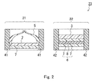
- the first ventilation member 21 and the second ventilation member 22 may not necessarily be integrated with each other. As illustrated in Fig. 2 , the first ventilation member 21 and the second ventilation member 22 may be separated from each other to form a ventilation member kit 23.
- the first gas permeable membrane 2 is supported by a first support body 41
- the second gas permeable membrane 3 and the absorbing layer 6 are supported by a second support body 42.
- the support body 41 and the support body 42 are fixed respectively to a first opening and a second opening of a housing, independently of each other.
- the structure of the first one-way valve 5 is not particularly limited.
- the one-way valve 5 shown in Fig. 1 is made of an elastic material.
- This type of valve has the advantages as follows; it is highly adaptable to various types of first gas permeable membranes 2 with various gas permeable areas, it can be processed easily into various valve shapes, and the setting of the pressure difference (between the interior and the exterior of the housing 51) at which the valve opens is easy.
- the one-way valve 5 is made of an elastic material, the one-way valve 5 can be kept closed without applying any force thereto when there is little pressure difference between the interior and the exterior of the housing 51 (when in the steady state condition), and therefore, it becomes easier to prevent the entry of water vapor into the housing 51 when in the steady state condition.
- the elastic material include rubber, elastomer, and thermoplastic resin.
- the one-way valve 5 does not necessarily have a structure that can completely block the movement of the gas from the exterior to the interior of the housing 51 as long as it has a structure that can block the movement substantially.
- the specific shape of the one-way valve 5 is not particularly limited. As illustrated in Fig. 3 , the one-way valve 5 may be fixed to the first gas permeable membrane 2 and a later-described reinforcing layer 7. Such a one-way valve 5 may be formed by a resin film or a metal film easily.
- the one-way valve 5 shown in Fig. 3 is supported by the first gas permeable membrane 2 and the reinforcing layer 7.
- the one-way valve 5 may be supported by any optional member as long as the one-way valve 5 is disposed so as to cover the first gas permeable membrane 2.
- first ventilation member 21, which is provided with the one-way valve 5 is depicted in Fig. 3 for clarity in illustration, and likewise, only the first or the second ventilation member may be depicted also in the figures that will be referred to later.
- the number of layers of the first gas permeable membrane 2 and the one-way valve 5, as well as the positional relationship between the first gas permeable membrane 2 and the one-way valve 5, in the ventilation member 1 (in the gas passage of the first ventilation member 21) may be determined as desired.
- the one-way valve 5 When the one-way valve 5 is disposed more outward than the first gas permeable membrane 2 as shown in Fig. 1 , the one-way valve 5 also may serve as a protective cover for protecting the first gas permeable membrane 2.
- the absorbing layer 6 shown in Fig. 1A has a structure in which a water absorbent 8 is sandwiched by a pair of reinforcing layers 7.
- the structure of the absorbing layer 6 is not limited to the example shown in Fig. 1A but should retain the water absorbent 8 in the gas passage of the second ventilation member 22.
- the water absorbent 8 may be sandwiched by a pair of second gas permeable membranes 3. In this case, the water absorbent 8 serves as the absorbing layer 6.
- the water absorbent 8 may be sandwiched by the second gas permeable membrane 3 and the reinforcing layer 7.
- the water absorbent 8 may be disposed by itself in the gas passage of the second ventilation member 22.
- the absorbing layer 6 may contain a binder resin that serves as the base material for retaining the shape of the absorbing layer 6.
- the absorbing layer 6 may be disposed by itself in the gas passage of the second ventilation member 22.
- Preferable binder resins include fluororesin and polyolefin, and an example of the fluororesin is polytetrafluoroethylene (PTFE).
- PTFE polytetrafluoroethylene
- the absorbing layer 6 also can serve as the second gas permeable membrane 3 by controlling the porosity and/or average pore diameter of the PTFE porous material (i.e., the second gas permeable membrane 3 and the absorbing layer 6 can be integrated with each other).
- the weight ratio of the water absorbent 8 to the binder resin contained in the absorbing layer 6 normally may be within the range of from 95:5 to 20:80, and preferably within the range of from 90:10 to 25:75. If the content of the binder resin is too small, the binder resin is difficult to become a base material, whereas if the content thereof is too large, the water absorption performance of the absorbing layer 6 degrades. Normally, the thickness of the absorbing layer 6 containing the binder resin should be within the range of from 0.05 mm to 50 mm, and preferably within the range of from 0.5 mm to 5 mm.
- a gap may exist between the second gas permeable membrane 3 and the absorbing layer 6, but when the second gas permeable membrane 3 and the absorbing layer 6 are in contact with each other as shown in Fig. 1 , the absorbing layer 6 also can serve as a reinforcing layer for the second gas permeable membrane 3.
- the water absorbent 8 is disposed in the entire gas permeable part (the entire gas permeable area) of the absorbing layer 6 in the absorbing layer 6 shown in Fig. 1
- the water absorbent 8 may be disposed in at least a portion of the gas permeable part the absorbing layer 6, as illustrated in Fig. 6 .
- the number of layers of the second gas permeable membrane 3 and the absorbing layer 6 as well as the positional relationship between the second gas permeable membrane 3 and the absorbing layer 6 in the ventilation member 1 (in the gas passage of the second ventilation member 22) may be determined as desired.
- the water absorbent 8 may be a common water-absorbent, an adsorbent, and/or a drying agent.
- the water absorbent 8 may be at least one material selected from a material that adsorbs moisture physically (physical adsorbent) and a material that reacts with moisture chemically (chemical absorbent).
- the two materials may be disposed so as to be mixed together in the absorbing layer 6 or the two materials may be disposed separately.
- the weight ratio of the physical adsorbent to the chemical absorbent contained in the water absorbent 8 is within the range of from 1:100 to 1:5, and preferably within the range of from 1:20 to 1:7.
- the water absorbent 8 may be an absorbent that absorbs corrosive substances (such as SO x , NO x , and HCl) in the atmosphere. In this case, the amounts of the corrosive substances that are introduced into the housing 51 can be reduced.
- corrosive substances such as SO x , NO x , and HCl
- the material that adsorbs moisture physically may include at least one material selected from silica such as silica gel, activated carbon, zeolite, alumina, boria, titanium oxide, sepiolite, and activated clay.
- the zeolite includes a molecular sieve, which is an artificial zeolite.
- the material that chemically reacts with moisture may include at least one substance selected from the group consisting of alkali metal oxides, alkaline-earth metal oxides, metal sulfates, metal halides, and metallic perchlorate salts.
- alkali metal oxides include Na 2 O and K 2 O.
- alkaline-earth metal oxides include CaO, MgO, SrO, and BaO.
- metal sulfates include CaSO 4 , MgSO 4 , FeSO 4 , and NiSO 4 .
- the metal halides include CaCl 2 , MgCl 2 , CrCl 2 , FeCl 2 , and NiCl 2 .
- metallic perchlorate salts examples include KClO 4 , NaClO 4 , Fe(ClO 4 ) 2 , Co(ClO 4 ) 2 , Ca(ClO 4 ) 2 , Mg(ClO 4 ) 2 , Ba(ClO 4 ) 2 , Mn(ClO 4 ) 2 .
- BaO, SrO, CaO, and CaSO 4 are preferable because of their large hygroscopic rates.
- the material that physically adsorbs moisture is used as the water absorbent 8, it is easy to remove the moisture from the water absorbent 8 by heat drying or the like (that is, it is easy to recycle and reuse it as the water absorbent 8).
- a material that changes its color by absorbing moisture may be added to the water absorbent 8.
- the just-mentioned material may include silica gel containing a cobalt salt, for example.
- the gas permeability of the first gas permeable membrane 2 with a pressure difference of 10 kPa being applied may be, but is not particularly limited to be, within the range of from 50 to 200,000 cm 3 /min ⁇ cm 2 , and preferably within the range of 100 to 100,000 cm 3 /min ⁇ cm 2 , from the viewpoint of removing the fogging in the housing 51 more quickly and preventing an excessive pressure increase in the housing 51.
- gas permeability with a pressure difference of 10 kPa being applied means the volume of a gas that passes through a gas permeable membrane per unit time and per unit area of the gas permeable membrane when a pressure difference of 10 kPa is produced between the two sides of the gas permeable membrane.
- Such a gas permeability may be measured using the Frazier air permeability testing method according to JIS L 1096 (1999) or the Gurley densometer testing method according to JIS P 8117.
- the meaning and the testing methods of the later-described "gas permeability with a pressure difference of 1 kPa being applied" are likewise.
- the gas permeable area of the first gas permeable membrane 2 may be, but is not particularly limited to be, within the range of from 5 to 5,000 mm 2 , and preferably within the range of from 30 to 3,000 mm 2 , from the viewpoint of removing the fogging in the housing 51 more quickly and preventing an excessive pressure increase in the housing 51.
- the gas permeability of the second gas permeable membrane 3 is not particularly limited, the gas permeability thereof with a pressure difference of 1 kPa being applied may be within the range of from 0.05 to 100 cm 3 /min ⁇ cm 2 , and preferably within the range of 0.1 to 50 cm 3 /min ⁇ cm 2 , from the viewpoint of extending the time until fogging will be produced in the housing 51.
- the gas permeable area of the second gas permeable membrane 3 may be, but is not particularly limited to be, within the range of from 1 to 2,000 mm 2 , and preferably within the range of from 5 to 1,000 mm 2 , from the viewpoint of further extending the time until fogging will be produced in the housing 51.
- the ratio of the gas permeable area of the first gas permeable membrane 2 and the gas permeable area of the second gas permeable membrane 3 may be set as appropriate depending on the characteristics required as the ventilation member 1.
- the ratio of (the gas permeable area of the first gas permeable membrane 2)/(the gas permeable area of the second gas permeable membrane 3) may be within the range of from about 0.01 to 1000, and preferably within the range of from about 0.05 to 500.
- the material and structure of the first and second gas permeable membranes are not particularly limited as long as a necessary gas permeation quantity can be ensured.
- a gas permeable membrane containing fabric, nonwoven fabric, net, porous material, or foamed material it is possible to employ a gas permeable membrane containing fabric, nonwoven fabric, net, porous material, or foamed material.
- a gas permeable membrane containing a porous material of fluororesin and/or a porous material of polyolefin is preferable from the viewpoints of water repellency (waterproofness), heat resistance, chemical resistance, and the like.
- fluororesin examples include polytetrafluoroethylene (PTFE), polychloro-trifluoroethylene, tetrafluoroethylene-hexafluoropropylene copolymer, tetrafluoroethylene-perfluoroalkylvinyl copolymer, tetrafluoroethylene-ethylene copolymer, and polyvinylidene fluoride (PVdF). It is especially preferable to use a PTFE porous material, which is capable of ensuring sufficient ventilation performance with a small gas permeable area and preventing the entry of foreign matter such as water and dust into the housing 51 highly effectively.
- the polyolefin examples include polyethylene, polypropylene, and ultrahigh-molecular-weight polyethylene.
- the average pore diameter of the porous material be within the range of from about 0.01 ⁇ m to 50 ⁇ m from the viewpoint of waterproofness.
- a porous material can be obtained by a common method for forming porous materials, such as a drawing method and an extraction method.
- the number of layers of each of the first gas permeable membrane 2 and the second gas permeable membrane 3 provided for the ventilation member 1 according to the present invention is not limited to one layer, and it may be set as desired.
- the reinforcing layer 7 is laminated with the first gas permeable membrane 2.
- the absorbing layer 6 containing the reinforcing layers 7 is disposed so as to be in contact with the second gas permeable membrane 3, and the absorbing layer 6 also serves as a reinforcing layer for the second gas permeable membrane 3.
- a reinforcing layer 7 may be laminated with at least one gas permeable membrane selected from the first gas permeable membrane 2 and the second gas permeable membrane 3, and the strength of the gas permeable membrane with which a reinforcing layer 7 is laminated can be improved.
- the number of layers of the reinforcing layer 7 laminated with the gas permeable membrane may be set as desired.
- the material and the structure of the reinforcing layer 7 are not particularly limited, but it is preferable that the reinforcing layer have better gas permeability than the gas permeable membrane.
- the reinforcing layer 7 that may be used include fabric, nonwoven fabric, mesh, net, sponge, foam, and porous material, which may be made of, for example, a resin or a metal.
- the reinforcing layer 7 may be joined to the gas permeable membrane.
- the joining may be performed by such techniques as adhesive lamination, heat lamination, heat bonding, and ultrasonic welding.
- At least one of the gas permeable membrane selected from the first and the second gas permeable membranes may be a liquid repellent (e.g. water repellent or oil repellent) membrane.
- the liquid repellency of the membrane can be achieved by a liquid repellent treatment for the membrane, and the treatment may be conducted by, for example, applying a substance having a small surface tension to the gas permeable membrane, then drying and thereafter curing it.
- the liquid repellent that may be used for the liquid repellent treatment include a solution containing a polymer material having perfluoroalkyl groups.
- the application of the liquid repellent to a gas permeable membrane may be conducted by a common technique, such as an impregnation method or a spraying method.
- the gas permeable membrane is liquid repellent treated, it is possible to prevent the gas permeable membrane from being plugged up because of the oil or the surfactant in the environment in which the ventilation member 1 is placed.
- the liquid repellent treatment is especially effective when the ventilation member 1 is used outdoors (for example, when used for a housing for ECUs or automobile lamps).
- thermoplastic resin As the material for the support body 4 from the viewpoint of moldability.
- examples that may be used include various thermoplastic elastomers such as olefin-based, styrene-based, urethane-based, ester-based, amide-based, and vinyl chloride-based thermoplastic elastomers; various thermoplastic resins such as polyolefin, polyamide, polyester, polyacetal, polysulfone, polyacrylic, and polyphenylene sulfide; and composite materials thereof.
- the various members that are supported by the support body 4 may be fixed to the support body 4 by using such techniques as heat-bonding, ultrasonic welding, and adhesive bonding. Especially, heat-bonding and ultrasonic welding techniques are simple and therefore preferable.
- first gas permeable membrane 2 is fixed to the support body 4
- damages to the first gas permeable membrane 2 can be minimized when the reinforcing layer 7 and the first gas permeable membrane 2 are laminated together and thereafter fixed to the support body 4.
- the second gas permeable membrane 3 is fixed to the support body 4
- damages to the second gas permeable membrane 3 can be minimized when the second gas permeable membrane 3 is laminated with the reinforcing layer 7 and/or the absorbing layer 6 and thereafter fixed to the support body 4.
- the shape of the support body 4 is not particularly limited as long as the purpose of the ventilation member 1 is met.
- the support body 4 may be formed using common molding techniques, such as injection molding and extrusion molding.
- the first support body 41 and the second support body 42 in the ventilation member kit 23 may be similar to the support body 4.
- each of the first gas permeable membrane 2, the second gas permeable membrane 3, and the absorbing layer 6 is supported directly by the support body 4; however, it is possible to dispose another member between each of the just-mentioned members and the support body 4. In this case, each of the just-mentioned members is supported by the support body 4 via the member that is disposed therebetween.
- the first gas permeable membrane 2 is supported by the support body 4 via the one-way valve 5 and a support layer 9.
- the material used for the support layer 9 may be similar to the material used for the support body 4, and the shape and structure thereof are not particularly limited.
- the specific configuration for integrating the first ventilation member 21 and the second ventilation member 22 together is not particularly limited.
- a ventilation member 1 having the configuration shown in Figs. 8A and 8B may be employed.
- a second gas permeable membrane 3 and an adsorbing layer 6, which are in a doughnut-like shape, are fixed in a substantially tubular support body 4.
- a one-way valve 5 and a laminated body of a first gas permeable membrane 2 and a reinforcing layer 7 are fixed on the inner sides of the second gas permeable membrane 3 and the adsorbing layer 6 via a support layer 9.
- FIG. 8A and 8B may be a ventilation member in which the second ventilation member 22 having the absorbing layer 6 is disposed in an outer circumferential part thereof and the first ventilation member 21 having the one-way valve 5 is disposed in an inner circumferential part thereof.
- Fig. 8B is a view in which the ventilation member 1 shown in Fig. 8A is viewed from the upper face (in other words, viewed in the direction along the arrow B in Fig. 8A ).
- the ventilation member of the present invention further may have a second one-way valve disposed so as to cover the second gas permeable membrane.
- Fig. 9 illustrates one example of the ventilation member 1 that has such a configuration.
- the ventilation member 1 shown in Fig. 9 further has a second one-way valve 10 supported by the support body 4 so as to cover the second gas permeable membrane 3.
- the gas flow direction of the second one-way valve 10 is the direction in which a gas passes from the exterior toward the interior of the housing 51 with the ventilation member 1 being fixed to the opening 52 of the housing 51 (i.e., the gas flow direction of the second one-way valve 10 and the gas flow direction of the first one-way valve 5 are opposite to each other).
- the second one-way valve 10 is disposed nearer to the external environment than the absorbing layer 6, which is located at an innermost position in the ventilation member 1 (i.e., in the gas passage of the second ventilation member 22) toward the housing 51.
- This configuration makes it possible to prevent the entry of water vapor into the absorbing layer 6 from the external environment and to extend the lifetime and replacement cycle of the absorbing layer 6 because the second one-way valve 10 can be closed when in the steady state condition.
- the material used for the second one-way valve 10 as well as the specific shape and structure of the second one-way valve 10 may be similar to those of the first one-way valve 5.
- the one-way valve 10 is made of an elastic material, the one-way valve 10 can be kept closed without applying any force thereto when in the steady state condition, and therefore, it becomes easier to prevent the entry of water vapor into the absorbing layer 6.
- the number of the second one-way valve 10 as well as the positional relationship between the second one-way valve 10 and the second gas permeable membrane 3 and/or the absorbing layer 6 in the ventilation member 1 (in the gas passage of the second ventilation member 22) may be determined as desired.
- the second one-way valve 10 When the second one-way valve 10 is disposed nearer to the external environment than the second gas permeable membrane 3 as shown in Fig. 9 , the second one-way valve 10 also may serve as a protective cover for protecting the first gas permeable membrane 2.
- the method for fixing the ventilation member 1 to the opening 52 of the housing 51 is not particularly limited, and common fixing methods may be employed.
- the ventilation member 1 may be fixed by inserting it into the opening 52, or as illustrated in Fig. 10 , the ventilation member 1 may be fixed so as to cover the opening 52.
- the outer diameter of the support body 4 be slightly larger than the inner diameter of the opening 52.
- the inner diameter of the support body 4 be slightly smaller than the outer diameter of the opening 52.
- bottom faces (denoted as C and C' in Fig. 11 ) of the ventilation member 1 and a surface of the housing 51 are adhesive-bonded together so as to cover the opening 52 of the housing 51.
- a male screw may be formed on the outer circumferential surface of the support body 4 of the ventilation member 1 and a female screw may be formed in the opening 52 of the housing 51 so that the support body 4 and the opening 52 can be screw-fastened together to fix the ventilation member 1. It is also possible to fix the ventilation member 1 by simply fitting the ventilation member 1 and the opening 52 together.
- FIG. 12 Another example of the ventilation member 1 according to the present invention is illustrated in Fig 12 .
- the ventilation member 1 shown in Fig. 12 further has a closed-bottomed protective cover 11 that covers the first gas permeable membrane 2 and the second gas permeable membrane 3.
- the protective cover 11 is supported by the support body 4 in such a manner that a space gap can exist between the gas permeable membranes and the protective cover 11 to ensure a gas passage from the external environment to the gas permeable membranes.
- Such ventilation member can prevent breakage or the like of the gas permeable membrane because the protective cover 11 hinders foreign matters from the exterior, such as stone chips, dust, and water, from making contact with the gas permeable membranes.
- the shape of the protective cover 11 and the method for supporting the protective cover 11 by the support body 4 are not particularly limited.
- a protrusion portion 12 that is formed on the support body 4 supports the protective cover and ensures the gas passage.
- the ventilation member according to the present invention may also be used not only in the configuration in which the first ventilation member 21 and the second ventilation member 22 are integrated with each other, as shown in, for example, Figs. 1A (1B ), ) 8A (8B) and 9 , but also as the ventilation member kit 23 having the first ventilation member 21 and the second ventilation member 22, as shown in Fig. 2 .
- the first and the second ventilation members may be fabricated or sold independently as separate ventilation members before they will be fixed to the first and the second openings of the housing.
- the first and the second ventilation members in the ventilation member kit 23 will be described.
- a first ventilation member 21 shown in Fig. 13 is provided with a first gas permeable membrane 2 and a support body 4 for supporting the first gas permeable membrane.
- the support body 4 is fixed so as to cover the opening 52 of the housing 51 at bottom faces (denoted as D and D' in Fig. 12 ) of the first ventilation member 21 by adhesive bonding.
- the first ventilation member 21 further has a first one-way valve (check valve) 5 supported by the support body 4 so as to cover the first gas permeable membrane 2.
- the gas flow direction of the first one-way valve 5 is the direction in which a gas passes from the interior toward the exterior of the housing 51 with the first ventilation member 21 being fixed to the opening 52 of the housing 51.
- the gas tends to move from the interior toward the exterior of the housing 51.
- the one-way valve 5 of the first ventilation member 21 opens up, so that the gas is allowed to permeate through the first gas permeable membrane 2 and is discharged quickly to the exterior of the housing 51.
- the fogging can be cleared quickly.
- the specific structure and configuration of the first ventilation member 21 may be similar to those of the previously-described first ventilation member 21 in the ventilation member 1 according to the present invention.
- the method for fixing the first ventilation member 21 to the housing 51 may be similar to the previously-described fixing method of the ventilation member 1 to the housing 51.
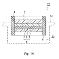
- a second ventilation member 22 shown in Fig. 14 is provided with a second gas permeable membrane 3 and a support body 4 for supporting the second gas permeable membrane.
- the support body 4 is inserted in and fixed to an opening 52 of a housing 51.
- the second ventilation member 22 further has an absorbing layer 6 containing a water absorbent for absorbing the moisture contained in the gas that passes through the opening 52.
- the absorbing layer 6 and the second gas permeable membrane 3 are disposed so that the above-mentioned gas permeates through the second gas permeable membrane 3 and the absorbing layer 6 successively (in whichever order). It can be said that the second gas permeable membrane 3 and the absorbing layer 6 are disposed on the gas passage of the second ventilation member 22.
- the gas tends to move from the exterior toward the interior of the housing 51, and the gas is led to permeate through the second gas permeable membrane 3 and the absorbing layer 6 and is introduced into the interior of the housing 51.
- the gas in which the amount of moisture is reduced by the absorbing layer 6 is introduced into the interior of the housing 51, and therefore, the time until fogging will be produced in the housing 51 can be extended. It is also possible to prevent the production of fogging in the housing 51 itself by optimizing the type and amount of the water absorbent contained in the absorbing layer 6.
- the specific structure and configuration of the second ventilation member 22 may be similar to those of the previously-described second ventilation member 22 in the ventilation member 1 according to the present invention.
- the method for fixing the second ventilation member 22 to the housing 51 may be similar to the previously-described fixing method of the ventilation member 1 to the housing 51.
- the ventilation member 1, the first ventilation member 21, and the second ventilation member 22 of the present invention may be provided with optional components other than the above-described components as needed.
- the gas tends to move from the exterior toward the interior of the tank.
- the one-way valve 5 closes up at this point, so that the gas is led to permeate through the second gas permeable membrane 3 and the absorbing layer 6 and is introduced into the interior of the tank.
- the gas in which the amount of moisture is reduced by the absorbing layer 6 is introduced into the interior of the tank, and therefore, the amount of water vapor that enters the interior of the tank can be reduced. It is also possible to prevent the entry of water vapor into the tank by optimizing the type and amount of the water absorbent contained in the absorbing layer 6.
- the one-way valve 5 opens up, so the gas is allowed to permeate through the first gas permeable membrane 2 and the second gas permeable membrane 3 and is discharged to the exterior of the tank.
- the gas in the tank can be discharged quickly to the exterior of the tank.
- a vented housing according to the present invention has a structure in which a ventilation member 1 and/or a ventilation member kit 23 according to the present invention is/are fixed to an opening of the housing.
- a ventilation member 1 and/or a ventilation member kit 23 according to the present invention is/are fixed to an opening of the housing.
- the gas flow direction of the one-way valve 5 provided in the ventilation member 1 (or the ventilation member kit 23) needs to be the direction in which the gas passes from the interior to the exterior of the housing.
- the type of the vented housing in which a ventilation member according to the present invention may be fixed is not particularly limited.
- Examples include electrical components such as headlamps, tail lamps, fog lamps, turn indicator lamps, reversing lamps, motor housings, pressure sensors, pressure switches, ECUs, batteries, and electric double layer capacitors, as well as electric products in which electronic devices and electronic circuits are accommodated, such as mobile telephones, cameras, electric shavers, electric toothbrushes, and lamps.
- the advantageous effects obtained are significant when the vented housing is an automobile electrical component, such as an automobile lamp.
- a vented tank according to the present invention has a structure in which a ventilation member 1 and/or a ventilation member kit 23 according to the present invention is/are fixed to an opening of the tank.
- a vented tank that can reduce the amount of water vapor that enters the interior of the tank and can discharge the gas in the tank quickly to the exterior of the tank when the pressure inside the tank increases.
- the gas flow direction of the one-way valve 5 provided in the ventilation member 1 (or the ventilation member kit 23) needs to be the direction in which the gas passes from the interior to the exterior of the tank.
- the type of the vented tank to which a ventilation member according to the present invention is fixed is not particularly limited. Examples may include containers for accommodating liquid therein, such as various bottles for chemicals, organic solvent tanks, and gas tanks.
- Fig. 1 five types of the ventilation members that have a structure as shown in Fig. 1 as the example samples and three types of comparative example samples were fabricated to evaluate the fogging characteristic, the fogging clearing characteristic, and the pressure difference eliminating characteristic for each of the ventilation member samples when fixed to an automobile lamp.
- a support body 4 as shown in Fig. 1 that has two holes (one of the holes, hole A had a diameter of 16 mm ⁇ , and the other one, hole B had a diameter of 10 mm ⁇ ) for placing gas permeable membranes therein was molded using a thermoplastic elastomer ("Milastomer 6030" made by Mitsui Chemicals, Inc.) by injection molding.
- a laminated material of a polytetrafluoroethylene (PTFE) porous film and a polyolefin non-woven fabric (“Temish” made by Nitto Denko Corp.: the gas permeability of the film with a pressure difference of 10 kPa being applied was 20,000 cm 3 /min ⁇ cm 2 ), serving as the laminated material of the reinforcing layer 7 and the first gas permeable membrane 2, was fixed in the hole A of the molded support body 4 by heat-bonding.
- a one-way valve 5 obtained by molding silicone rubber (made by Shin-Etsu Silicone Co., Ltd.) was fixed further thereto so as to cover the entire surface of the fixed laminated material.
- the gas permeable area of the laminated material was 100 mm 2 , and it was confirmed separately that the one-way valve 5 opens when the pressure inside the lamp becomes about 1 kPa higher than that of the external environment.
- barium oxide (BaO) powder serving as the water absorbent 8
- BaO porous films (Temish” made by Nitto Denko Corp.: the gas permeability of the film with a pressure difference of 1 kPa being applied was 20 cm 3 /min ⁇ cm 2 ), to form a laminated material (gas permeable area 25 mm 2 ), which serves as the second gas permeable membrane 3 and the absorbing layer 6.
- the laminated material was fixed in the hole B of the support body 4 by a compression method.
- a ventilation member 1 (sample 1) shown in Fig. 1 was fabricated.
- the PTFE porous films were subjected to an oil repellent treatment.
- a support body 4 as shown in Fig. 1 that has two holes for disposing gas permeable membranes therein (both holes having a diameter of 16 mm ⁇ ) was molded by injection molding using a polypropylene resin ("J802H” made by Ube Industries, Ltd.).
- a laminated material of a PTFE porous film (“Temish” made by Nitto Denko Corp.) and a net made of polyolefin ("Conwed Net ON3330" made by Nisseki Plasto Co., Ltd.), serving as the laminated material of the reinforcing layer 7 and the first gas permeable membrane 2, (formed by heat lamination: the gas permeability of the film with a pressure difference of 10 kPa being applied was 50,400 cm 3 /min ⁇ cm 2 ) was fixed in one of the holes in the molded support body 4 by heat-bonding.
- a one-way valve 5 obtained by molding nitrile rubber was fixed further thereto so as to cover the entire surface of the fixed laminated material.
- the gas permeable area of the laminated material is 78.5 mm 2 , and it was confirmed separately that the one-way valve 5 opens when the pressure inside the lamp becomes about 1.2 kPa higher than that of the external environment.
- a mixture of calcium oxide (CaO) powder and activated carbon, serving as the water absorbent 8 was sandwiched between a pair of polypropylene porous films ("NTG" made by Nitto Denko Corp.: the gas permeability of the film with a pressure difference of 1 kPa being applied was 1.2 cm 3 /min ⁇ cm 2 ) to form a laminated material (gas permeable area 78.5 mm 2 ), serving as the second gas permeable membrane 3 and the absorbing layer 6.
- the laminated material was fixed in the other hole of the support body 4 by heat-bonding.
- a ventilation member 1 (sample 2) shown in Fig. 1 was fabricated.
- the weight ratio of the calcium oxide and the activated carbon contained in the water absorbent 8 was 2:8.
- a support body 4 as shown in Fig. 1 that has two holes (one of the holes, hole A had a diameter of 10 mm ⁇ , and the other one, hole B had a diameter of 30 mm ⁇ ) for placing gas permeable membranes therein was molded using an ethylene propylene rubber (EPDM) ("EP21" made by JSR Corp.) by vulcanization molding.
- EPDM ethylene propylene rubber
- an ultrahigh-molecular-weight polyethylene porous film ("Sunmap" made by Nitto Denko Corp.: the gas permeability of the film with a pressure difference of 10 kPa being applied was 106,700 cm 3 /min ⁇ cm 2 ), serving as the first gas permeable membrane 2, was fixed in the hole A of the molded support body 4 by a rubber adhesive.
- a one-way valve 5 obtained by molding a polyethylene film was fixed further thereto so as to cover the entire surface of the first gas permeable membrane 2 that has been fixed.
- the gas permeable area of the laminated material was 19.6 mm 2 , and it was confirmed separately that the one-way valve 5 opens when the pressure inside the lamp becomes about 0.7 kPa higher than that of the external environment.
- potassium oxide (K 2 O) powder serving as the water absorbent 8 was sandwiched between a pair of PTFE porous films ("Temish” made by Nitto Denko Corp.: the gas permeability of the film with a pressure difference of 1 kPa being applied was 58 cm 3 /min ⁇ cm 2 ), to form a laminated material (gas permeable area 380 mm 2 ), and zeolite (made by Asahi Glass Co., Ltd.), serving as the water absorbent 8, likewise was sandwiched between a pair of PTFE porous films, the same as the just-mentioned ones, to form a laminated material (gas permeable area 380 mm 2 ).
- a support body 4 as shown in Fig. 1 that has two holes (one of the holes, hole A had a diameter of 55 mm ⁇ , and the other one, hole B had a diameter of 8 mm ⁇ ) for placing gas permeable membranes therein was molded using a polyester elastomer ("Hytrel" made by Toray-DuPont Corp.) by injection molding.
- a laminated material of a PTFE porous film ("Temish” made by Nitto Denko Corp.) and a net made of polyester ("Bellcouple” made by Kanebo Inc.) (the gas permeability of the film with a pressure difference of 10 kPa being applied was 54 cm 3 /min ⁇ cm 2 ), serving as the laminated material of the reinforcing layer 7 and the first gas permeable membrane 2, was fixed in the hole A of the molded support body 4 by heat-bonding.
- a one-way valve 5 obtained by molding silicone rubber (made by Shin-Etsu Silicone Co., Ltd.) was fixed further thereto so as to cover the entire surface of the fixed laminated material.
- the gas permeable area of the laminated material was 1,590 mm 2 , and it was confirmed separately that the one-way valve 5 opens when the pressure inside the lamp becomes about 1 kPa higher than that of the external environment.
- a mixture of magnesium oxide (MgO) powder and calcium chloride (CaCl 2 ) powder, serving as the water absorbent 8 was sandwiched between a pair of polyester porous films (the gas permeability of the film with a pressure difference of 1 kPa being applied was 98 cm 3 /min ⁇ cm 2 ) to form a laminated material (gas permeable area: 3.1 mm 2 ), serving as the second gas permeable membrane 3 and the absorbing layer 6.
- the laminated material was fixed in the hole B of the support body 4 by heat-bonding.
- a ventilation member 1 (sample 4) shown in Fig. 1 was fabricated.
- the weight ratio of the magnesium oxide and the calcium chloride contained in the water absorbent 8 was 5:5.
- a support body 4 as shown in Fig. 1 that has two holes (one of the holes, hole A had a diameter of 75 mm ⁇ , and the other one, hole B had a diameter of 60 mm ⁇ ) for placing gas permeable membranes therein was molded using a thermoplastic elastomer ("Milastomer 6030" made by Mitsui Chemicals, Inc.) by injection molding.
- an ultrahigh-molecular-weight polyethylene porous film (“Sunmap” made by Nitto Denko Corp.: the gas permeability of the film with a pressure difference of 10 kPa being applied is 218,000 cm 3 /min ⁇ cm 2 ), serving as the first gas permeable membrane 2, was fixed in the hole A of the molded support body 4 by heat-bonding.
- a one-way valve 5 obtained by molding a thermoplastic elastomer was fixed further thereto so as to cover the entire surface of the fixed laminated material.
- the gas permeable area of the laminated material was 3,318 mm 2 , and it was confirmed separately that the one-way valve 5 opens when the pressure inside the lamp becomes about 2 kPa higher than that of the external environment.
- a PTFE resin was mixed with strontium oxide (SrO) and silica gel, serving as the water absorbent 8, and the resultant mixture was extrusion-molded and drawing-processed to form an absorbing layer 6 in which a porous material of PTFE was the base material and the water absorbent 8 was dispersed in the base material.
- strontium oxide SrO
- silica gel serving as the water absorbent 8
- a laminated material of a second gas permeable membrane 3 (PTFE porous film: "Temish” made by Nitto Denko Corp.) and the just-described absorbing layer 6 was fixed in the hole B of the support body 4 by heat-bonding (the laminated material had a gas permeability of 0.38 cm 3 /min ⁇ cm 2 with a pressure difference of 1 kPa being applied).
- a ventilation member 1 (sample 5) was fabricated.
- the gas permeable area of the laminated material was 1,963 mm 2 .
- thermoplastic elastomer As used in the sample 1, a support body having one hole (18 mm ⁇ ) for placing a gas permeable membrane was molded by injection molding. Next, the same gas permeable membrane as the first gas permeable membrane 2 in the sample 1 was fixed in the just-mentioned hole by heat-bonding to prepare a sample A. The gas permeable area of the gas permeable membrane fixed was set to be 125 mm 2 .
- the same support body as that used in the sample A was molded by injection molding, and a polyester film was fixed so as to plug the opening of the hole in the molded support body by heat-bonding, to prepare a sample B.
- a ventilation member that has a structure as shown in Fig. 16 was fabricated as a sample C.
- a support body having one hole (10 mm ⁇ ) for placing a gas permeable membrane was molded by injection molding.
- the same gas permeable membrane as the first gas permeable membrane 2 in the sample 1 was fixed on the just-mentioned hole by heat-bonding.
- a protective cover made of a polypropylene resin was fitted onto the support body.
- a ventilation member (sample C) as shown in Fig. 16 was fabricated.
- the gas permeable area of the gas permeable membrane fixed was set to be 79 mm 2 .
- each of the samples 1 to 5 and the samples A to C fabricated in these manners was fixed to an opening (fitting hole) 63 of an automobile lamp (lamp) 61 (made by Visteon Corp.: the internal volume of the housing was about 4,000 cm 2 ) shown in Fig. 15 to evaluate the time until fogging will be produced in the lamp 61 (fogging characteristic), the time until the produced fogging will be cleared up when fogging has been produced in the housing (fogging clearing characteristic), and the pressure difference eliminating characteristic.
- the evaluation methods are described below.
- the lamp 61 with the opening 63 being open was placed in a dryer and was retained in an atmosphere at 50°C and 10 to 30% RH (RH: relative humidity) for 5 hours.
- each of the ventilation member samples was fixed so as to be inserted in the opening 63, and using a thermostatic chamber capable of setting two different conditions, the lamp 61 was retained for 24 hours in such conditions that a lens unit 64 was in an atmosphere at 5°C and 50% RH and a main unit 62 was in an atmosphere at 40°C and 90% RH.
- Fogging clearing characteristic was evaluated for each of the lamps 61 in which fogging had been produced on the inner surface of the lens unit 64 during the evaluation of the fogging characteristic.
- the evaluation was conducted as follows.
- the lamp 61 was retained in an atmosphere at 25°C and 50% RH, and wind was applied from the lens unit 64 side to the lamp at a wind speed of 1.7 ⁇ 0.1 m/sec. and a constant volume of air, to measure the time until the fogging produced on the inner surface of the lens unit 64 was cleared up, which was employed as the fogging clearing characteristic.
- the fogging produced on the inner surface of the lens unit 64 was not cleared even after 24 hours after the start of the evaluation, it was determined as "unable to fogging clearing.”
- each of the ventilation member samples was fixed so as to be inserted in the opening 63 of a lamp 61, and the lamps 61 with the ventilation member samples fixed were retained in an atmosphere at 5°C for 4 hours.
- the temperature of the atmosphere in which the lamps 61 were retained was elevated from 4°C to 85°C over a 15 minute period, and then, the difference between the pressure of the interior of the lamp 61 and that of the exterior of the lamp 61 was measured.
- the case in which the pressure difference exceeded 10 kPa in the temperature increase period is denoted by “ ⁇ ” which means “poor,” and the case in which the pressure difference was 10 kPa or less in the period is denoted by a white circle " ⁇ " which means "good.”
- the present invention makes it possible to provide a ventilation member and a ventilation member kit that can extend the time until fogging will be produced in a housing and also can shorten the time until the produced fogging will be cleared up even when the interior of the housing has been fogged.
- the invention makes it possible to provide a vented housing that can extend the time until fogging will be produced in the housing and can clear the fogging up quickly even when fogging has been produced.
- the present invention makes it possible to provide a ventilation member and a ventilation member kit that can reduce the amount of water vapor that enters the interior of a tank and can discharge a gas in the tank to the exterior of the tank quickly when the pressure inside the tank increases.
- the ventilation member (ventilation member kit) according to the present invention may be used for various housings or tanks without any particular limitations.
- Examples of the vented housing using the ventilation member (ventilation member kit) according to the present invention include: automobile lamps such as headlamps, tail lamps, fog lamps, turn indicator lamps, and reversing lamps; automobile electrical components such as motor housings, pressure sensors, pressure switches, and ECUs; electrical components such as batteries and electric double layer capacitors; and electric appliances such as mobile telephones, cameras, electric shavers, electric toothbrushes, indoor lamps, and outdoor lamps.
- Examples of the vented tank that employs the ventilation member (ventilation member kit) according to the present invention include various bottles for chemicals, organic solvent tanks, and gas tanks.
Landscapes
- Engineering & Computer Science (AREA)
- General Engineering & Computer Science (AREA)
- Mechanical Engineering (AREA)
- Chemical & Material Sciences (AREA)
- Analytical Chemistry (AREA)
- General Chemical & Material Sciences (AREA)
- Oil, Petroleum & Natural Gas (AREA)
- Chemical Kinetics & Catalysis (AREA)
- Microelectronics & Electronic Packaging (AREA)
- Drying Of Gases (AREA)
- Separation Using Semi-Permeable Membranes (AREA)
- Arrangement Of Elements, Cooling, Sealing, Or The Like Of Lighting Devices (AREA)
- Self-Closing Valves And Venting Or Aerating Valves (AREA)
- Check Valves (AREA)
- Non-Portable Lighting Devices Or Systems Thereof (AREA)
- Solid-Sorbent Or Filter-Aiding Compositions (AREA)
Abstract

Description
- The present invention relates to a ventilation member and a ventilation member kit that are fixed to a tank, or to a housing for electrical components (typically automobile electrical components) for ensuring ventilation between the interior and the exterior of the tank or the housing and suppressing the entry of foreign matter into the interior of the tank or the housing. The invention also relates to a vented housing and a vented tank in which the ventilation member and/or the ventilation member kit is/are fixed.
- Conventionally, ventilation members are attached to housings of electric appliances such as mobile telephones, cameras, and of automobile electrical components including lamps, pressure sensors, and ECUs (Electrical Control Units), in order to ensure ventilation between the interior and the exterior of the housings and to prevent the entry of foreign matter into the interior of the housings. Attaching such ventilation members to the housings makes it possible to prevent the entry of water, dust, and the like into the interior of the housings and at the same time to achieve the following; the pressure change inside the housing associated with temperature change can be alleviated, sound can be transmitted between the interior and the exterior of the housing, and the gas produced in the interior of the housing can be discharged to the exterior of the housing.
- One example of such a ventilation member is disclosed in
JP 2001-143524A ventilation member 101 disclosed inDocument 1 has, as shown inFig. 16 , atubular support body 103 and a closed-bottomedprotective cover 104. A gaspermeable membrane 102 is disposed on one end face of thetubular support body 103. Theprotective cover 104 is fitted to thesupport body 103 so as to cover the gaspermeable membrane 102. Theventilation member 101 is fixed to ahousing 105 so as to cover anopening 106 of thehousing 105, and gas is allowed to permeate through the gaspermeable membrane 102 so that ventilation between the interior and the exterior of thehousing 105 is ensured. Theprotective cover 104 is provided in order to prevent the breakage of the gaspermeable membrane 102 caused by, for example, contact with foreign objects. - The
conventional ventilation member 101, however, allows the gas inside thehousing 105 and the gas outside thehousing 105 to be in communication with each other via the gaspermeable membrane 102 at all times, and therefore, water vapor outside thehousing 105 may enter the interior of thehousing 105, producing water droplets on the inner surface of the housing 105 (i.e., fogging the inner surface of the housing 105). For example, when the housing is a lamp that is one type of automobile electrical components, the water droplets (fogging) can become a cause of reducing the light intensity of the light emitted from the lamp. Such fogging is apt to occur by turning off the lamp when the air temperature is low and the humidity of the exterior the housing is high (for example, when it is raining or snowing in winter). From the viewpoint of improving the automobile's safety, there is a need for a ventilation member that can extend the time until the fogging will be produced and that allows the fogging to disappear quickly after turning on the lamp, for example, even if the fogging is produced. The same characteristics have been required for the ventilation members used for other kinds of housings. - It is possible to delay the generation of water droplets (production of fogging) by reducing the gas permeable area of the gas permeable membrane provided for the ventilation member to decrease the amount of the water vapor that enters the interior of the housing per unit time; however, in this method, the amount of the water vapor discharged to the exterior of the housing per unit time also decreases simultaneously, and therefore, it takes a long time before the generated water droplets disappear (i.e., until fogging will be cleared up). In addition, when electricity is passed through an electrical component, such as a lamp, in which the interior of the housing heats up during electricity application, when fogging has been produced therein, the water droplets are heated and water vapor is produced; however, the ventilation member provided with a gas permeable membrane having a small gas permeable area requires a long time to release the produced water vapor to the exterior of the housing.
- When such a conventional ventilation member is attached to a tank (such as a bottle for chemicals, an organic solvent tank, and a gas tank), it is possible to obtain similar advantageous effects to those in the case where the ventilation member is attached to the housing, while preventing the entry of water, dust, and the like into the tank.
- However, when the
conventional ventilation member 101 is attached to a tank, the gas inside the tank and the gas outside the tank are in communication with each other via the gaspermeable membrane 102 at all times, as in the case where theconventional ventilation member 101 is attached to thehousing 105. Consequently, water vapor outside the tank may enter the interior of the tank, causing adverse effects on the liquid accommodated in the tank or causing moisture to accumulate in the tank. - Accordingly, it is an object of the present invention to provide a ventilation member that can extend the time until fogging will be produced in the housing and shorten the time until the produced fogging will be cleared up even when the interior of the housing has been fogged, by allowing the ventilation member to have a structure that has not been available before. It is also an object of the invention to provide a vented housing using the just-mentioned ventilation member.
- It is also an object of the present invention to provide a ventilation member that can reduce the amount of water vapor entering the interior of a tank and can discharge the gas in the tank quickly to the exterior of the tank when the pressure inside the tank increases, by allowing the ventilation member to have a structure that has not been available before. It is also an object of the invention to provide a vented tank that uses the just-mentioned ventilation member.
- A ventilation member according to the present invention includes: a first gas permeable membrane, a second gas permeable membrane, and an absorbing layer allowing a gas passing through an opening of a housing or a tank to permeate therethrough, with the ventilation member being fixed to the opening; a support body for supporting the first gas permeable membrane, the second gas permeable membrane, and the absorbing layer; and a first one-way valve disposed so as to cover the first gas permeable membrane. The first gas permeable membrane and the second gas permeable membrane are disposed in such a manner that the gas permeates through the gas permeable membranes independently of each other. The second gas permeable membrane and the absorbing layer are disposed in such a manner that the gas permeates through the second gas permeable membrane and the absorbing layer successively. The absorbing layer contains a water absorbent.
- A ventilation member kit according to the present invention includes: a first ventilation member comprising a first gas permeable membrane allowing a gas passing through a first opening of a housing or a tank to permeate therethrough, with the first ventilation member being fixed to the first opening, a first support body for supporting the first gas permeable membrane, and a first one-way valve disposed so as to cover the first gas permeable membrane; and a second ventilation member comprising a second gas permeable membrane and an absorbing layer allowing a gas passing through a second opening of the housing or the tank to permeate therethrough, with the second ventilation member being fixed to the second opening, and a second support body for supporting the second gas permeable membrane and the absorbing layer, wherein in the second ventilation member, the second gas permeable membrane and the absorbing layer are disposed in such a manner that the gas permeates through the second gas permeable membrane and the absorbing layer successively, and the absorbing layer contains a water absorbent.
- A vented housing according to the present invention is a vented housing having an opening for allowing gas to pass therethrough, and includes the foregoing ventilation member according to the present invention. The ventilation member is fixed to the opening in such a manner that a gas flow direction of the first one-way valve of the ventilation member is a direction in which the gas passes from an interior to an exterior of the housing.
- In another embodiment, a vented housing according to the present invention is a vented housing having first and second openings for allowing gas to pass therethrough, and includes the foregoing ventilation member kit according to the present invention. The first ventilation member of the ventilation member kit is fixed to the first opening in such a manner that a gas flow direction of the first one-way valve of the first ventilation member is a direction in which the gas passes from an interior to an exterior of the housing. The second ventilation member of the ventilation member kit is fixed to the second opening.
- A vented tank according to the present invention is a vented tank having an opening for allowing gas to pass therethrough, and includes the foregoing ventilation member according to the present invention. The ventilation member is fixed to the opening in such a manner that a gas flow direction of the first one-way valve of the ventilation member is a direction in which the gas passes from an interior to an exterior of the tank.
- In another embodiment, a vented tank according to the present invention is a vented tank having first and second openings for allowing gas to pass therethrough, and includes the foregoing ventilation member kit according to the present invention. The first ventilation member of the ventilation member kit is fixed to the first opening in such a manner that a gas flow direction of the first one-way valve of the first ventilation member is a direction in which the gas passes from an interior to an exterior of the tank. The second ventilation member of the ventilation member kit is fixed to the second opening.
- The present invention makes it possible to extend the time until fogging will be produced in a housing and to shorten the time until the produced fogging will be cleared up even when the interior of the housing has been fogged, by employing a one-way valve (check valve) and an absorbing layer containing a water absorbent to control the gas flow from the exterior to the interior of the housing and the gas flow from the interior to the exterior of the housing.
- In addition, the present invention makes it possible to reduce the amount of water vapor that enters the interior of a tank and to discharge a gas in the tank quickly to the exterior of the tank when the pressure inside the tank increases, by employing a one-way valve (check valve) and an absorbing layer containing a water absorbent to control the gas flow from the exterior to the interior of the tank and the gas flow from the interior to the exterior of the tank.
- These advantageous effects also are obtained by the ventilation member kit provided with a ventilation member (first ventilation member) having the one-way valve and a ventilation member (second ventilation member) having the absorbing layer.
-
-
Fig. 1A is a cross-sectional view schematically illustrating one example of the ventilation member according to the present invention. -
Fig. 1B is a schematic view of the ventilation member shown inFig. 1A , viewed from the top. -
Fig. 2 is a cross-sectional view schematically illustrating one example of the ventilation member kit according to the present invention. -
Fig. 3 is a cross-sectional view schematically illustrating one example of the structure of the ventilation member according to the present invention. -
Fig. 4A is a cross-sectional view schematically illustrating one example of the structure of the ventilation member according to the present invention. -
Fig. 4B is a cross-sectional view schematically illustrating one example of the structure of the ventilation member according to the present invention. -
Fig. 5 is a cross-sectional view schematically illustrating one example of the structure of the ventilation member according to the present invention. -
Fig. 6 is a cross-sectional view schematically illustrating one example of the structure of the ventilation member according to the present invention. -
Fig. 7 is a cross-sectional view schematically illustrating another example of the ventilation member according to the present invention. -
Fig. 8A is a cross-sectional view schematically illustrating still another example of the ventilation member according to the present invention. -
Fig. 8B is a schematic view of the ventilation member shown inFig. 8A , viewed from the top. -
Fig. 9 is a cross-sectional view schematically illustrating yet another example of the ventilation member according to the present invention. -
Fig. 10 is a schematic cross-sectional view for illustrating one example of how to fix the ventilation member, according to the present invention, to a housing. -
Fig. 11 is a schematic cross-sectional view for illustrating another example of how to fix the ventilation member, according to the present invention, to the housing. -
Fig. 12 is a cross-sectional view schematically illustrating still another example, different from the foregoing examples, of the ventilation member according to the present invention. -
Fig. 13 is a cross-sectional view schematically illustrating yet another example, different from the foregoing examples, of the ventilation member according to the present invention. -
Fig. 14 is a cross-sectional view schematically illustrating further another example, different from the foregoing examples, of the ventilation member according to the present invention. -
Fig. 15 is a side view for illustrating the shape of an automobile lamp, which is used as a housing in an example. -
Fig. 16 is a cross-sectional view schematically illustrating one example of a conventional ventilation member. - Hereinbelow, preferred embodiments of the present invention are described with reference to the drawings. In the following description, the same parts are designated by the same reference numerals, and the repetitive description thereof may be omitted.
- One example of the ventilation member according to the present invention is illustrated in
Figs. 1A and 1B . - A
ventilation member 1 shown inFigs. 1A and 1B is provided with a first gaspermeable membrane 2, a second gaspermeable membrane 3, and asupport body 4 for supporting the first and the second gas permeable membranes. Thesupport body 4 is inserted in and fixed to anopening 52 of ahousing 51. The first gaspermeable membrane 2 and the second gaspermeable membrane 3 are juxtaposed in theopening 52. The gas passing through theopening 52 can permeate through the gas permeable membranes independently. Theventilation member 1 further is provided with a first one-way valve 5 (check valve) supported by thesupport body 4 so as to cover the first gas permeable membrane, and anabsorbing layer 6 containing a water absorbent for absorbing the moisture contained in the gas that passes through theopening 52. Theabsorbing layer 6 and the second gaspermeable membrane 3 are disposed so that the above-mentioned gas permeates through the second gaspermeable membrane 3 and theabsorbing layer 6 successively (in whichever order). The gas flow direction of the first one-way valve 5 is a direction in which the gas passes from the interior to the exterior of thehousing 51 with theventilation member 1 being fixed to theopening 52 of thehousing 51. - It can be said that the
ventilation member 1 is a ventilation member in which afirst ventilation member 21 provided with the first one-way valve 5 and asecond ventilation member 22 provided with theabsorbing layer 6 are integrated. It also can be said that the gas passage of thefirst ventilation member 21 and the gas passage of thesecond ventilation member 22 are independent of each other, when focusing on the gas permeable membranes provided for the respective ventilation members. It also can be said that the one-way valve 5 is disposed in the gas passage of thefirst ventilation member 21 and that the second gaspermeable membrane 3 and theabsorbing layer 6 are disposed on the gas passage of thesecond ventilation member 22. It should be noted that inFig. 1B , theventilation member 1 shown inFig. 1A is viewed from the top (in other words, viewed in the direction along the arrow A inFig. 1A), and Fig. 1B shows the state in which the one-way valve 5 is open for clarity in illustration (inFig. 1A , the one-way valve 5 is closed). It is likewise inFig. 8B , which will be referred to later. - When the interior of the
housing 51 becomes a negative pressure condition relative to the external environment, the gas tends to move from the exterior toward the interior of thehousing 51. However, the one-way valve 5 closes up at this point, so that the gas is led to permeate through the second gaspermeable membrane 3 and theabsorbing layer 6 and is introduced into the interior of the housing 51 (i.e., the gas is introduced through thesecond ventilation member 22 to the interior of the housing 51). At this time, the gas in which the amount of moisture is reduced by the absorbinglayer 6 is introduced into the interior of thehousing 51, and therefore, the time until fogging will be produced in thehousing 51 can be extended. It is also possible to prevent the production of fogging in thehousing 51 by optimizing the type and amount of the water absorbent contained in theabsorbing layer 6. - Conversely, when the interior of the
housing 51 becomes a pressurized condition relative to the external environment, the gas tends to move from the interior toward the exterior of thehousing 51. And, the one-way valve 5 opens up at this point, so the gas is allowed to permeate through both the firstpermeable membrane 2 and the second gaspermeable membrane 3 and is discharged to the exterior of the housing 51 (i.e., the gas is discharged to the exterior of thehousing 51 via thefirst ventilation member 21 and the second ventilation member 22). Thus, even when fogging is developed in thehousing 51, the fogging can be cleared quickly since the gas within thehousing 51 can be discharged quickly. Moreover, it is possible to prevent an excessive pressure increase in thehousing 51. - The
first ventilation member 21 and thesecond ventilation member 22 may not necessarily be integrated with each other. As illustrated inFig. 2 , thefirst ventilation member 21 and thesecond ventilation member 22 may be separated from each other to form aventilation member kit 23. In theventilation member kit 23 shown inFig. 2 , the first gaspermeable membrane 2 is supported by afirst support body 41, and the second gaspermeable membrane 3 and theabsorbing layer 6 are supported by asecond support body 42. Thesupport body 41 and thesupport body 42 are fixed respectively to a first opening and a second opening of a housing, independently of each other. - The structure of the first one-
way valve 5 is not particularly limited. The one-way valve 5 shown inFig. 1 is made of an elastic material. This type of valve has the advantages as follows; it is highly adaptable to various types of first gaspermeable membranes 2 with various gas permeable areas, it can be processed easily into various valve shapes, and the setting of the pressure difference (between the interior and the exterior of the housing 51) at which the valve opens is easy. Moreover, when the one-way valve 5 is made of an elastic material, the one-way valve 5 can be kept closed without applying any force thereto when there is little pressure difference between the interior and the exterior of the housing 51 (when in the steady state condition), and therefore, it becomes easier to prevent the entry of water vapor into thehousing 51 when in the steady state condition. Examples of the elastic material include rubber, elastomer, and thermoplastic resin. - The one-
way valve 5 does not necessarily have a structure that can completely block the movement of the gas from the exterior to the interior of thehousing 51 as long as it has a structure that can block the movement substantially. - The specific shape of the one-
way valve 5 is not particularly limited. As illustrated inFig. 3 , the one-way valve 5 may be fixed to the first gaspermeable membrane 2 and a later-described reinforcinglayer 7. Such a one-way valve 5 may be formed by a resin film or a metal film easily. - The one-
way valve 5 shown inFig. 3 is supported by the first gaspermeable membrane 2 and the reinforcinglayer 7. The one-way valve 5 may be supported by any optional member as long as the one-way valve 5 is disposed so as to cover the first gaspermeable membrane 2. It should be noted that only thefirst ventilation member 21, which is provided with the one-way valve 5, is depicted inFig. 3 for clarity in illustration, and likewise, only the first or the second ventilation member may be depicted also in the figures that will be referred to later. - The number of layers of the first gas
permeable membrane 2 and the one-way valve 5, as well as the positional relationship between the first gaspermeable membrane 2 and the one-way valve 5, in the ventilation member 1 (in the gas passage of the first ventilation member 21) may be determined as desired. When the one-way valve 5 is disposed more outward than the first gaspermeable membrane 2 as shown inFig. 1 , the one-way valve 5 also may serve as a protective cover for protecting the first gaspermeable membrane 2. - The
absorbing layer 6 shown inFig. 1A has a structure in which awater absorbent 8 is sandwiched by a pair of reinforcinglayers 7. However, the structure of theabsorbing layer 6 is not limited to the example shown inFig. 1A but should retain thewater absorbent 8 in the gas passage of thesecond ventilation member 22. For example, as illustrated inFig. 4A , thewater absorbent 8 may be sandwiched by a pair of second gaspermeable membranes 3. In this case, thewater absorbent 8 serves as the absorbinglayer 6. As illustrated inFig. 4B , thewater absorbent 8 may be sandwiched by the second gaspermeable membrane 3 and the reinforcinglayer 7. When thewater absorbent 8 itself has a shape that can be supported by the support body 4 (for example, when thewater absorbent 8 is in a porous film form), thewater absorbent 8 may be disposed by itself in the gas passage of thesecond ventilation member 22. - The
absorbing layer 6 may contain a binder resin that serves as the base material for retaining the shape of theabsorbing layer 6. In this case, the absorbinglayer 6 may be disposed by itself in the gas passage of thesecond ventilation member 22. Preferable binder resins include fluororesin and polyolefin, and an example of the fluororesin is polytetrafluoroethylene (PTFE). When the PTFE is used as the binder resin, it is possible to form anabsorbing layer 6 that uses a porous material of PTFE as the base material and in which thewater absorbent 8 is placed in the pores of the PTFE porous material, depending on the formation method of theabsorbing layer 6. In this case, the absorbinglayer 6 also can serve as the second gaspermeable membrane 3 by controlling the porosity and/or average pore diameter of the PTFE porous material (i.e., the second gaspermeable membrane 3 and theabsorbing layer 6 can be integrated with each other). - The weight ratio of the
water absorbent 8 to the binder resin contained in theabsorbing layer 6 normally may be within the range of from 95:5 to 20:80, and preferably within the range of from 90:10 to 25:75. If the content of the binder resin is too small, the binder resin is difficult to become a base material, whereas if the content thereof is too large, the water absorption performance of theabsorbing layer 6 degrades. Normally, the thickness of theabsorbing layer 6 containing the binder resin should be within the range of from 0.05 mm to 50 mm, and preferably within the range of from 0.5 mm to 5 mm. - As illustrated in
Fig. 5 , a gap may exist between the second gaspermeable membrane 3 and theabsorbing layer 6, but when the second gaspermeable membrane 3 and theabsorbing layer 6 are in contact with each other as shown inFig. 1 , the absorbinglayer 6 also can serve as a reinforcing layer for the second gaspermeable membrane 3. - Although the
water absorbent 8 is disposed in the entire gas permeable part (the entire gas permeable area) of theabsorbing layer 6 in theabsorbing layer 6 shown inFig. 1 , thewater absorbent 8 may be disposed in at least a portion of the gas permeable part theabsorbing layer 6, as illustrated inFig. 6 . In order to reduce the amount of moisture in the gas introduced into the interior of thehousing 51 more reliably, it is preferable that thewater absorbent 8 be disposed in the entire gas permeable part of theabsorbing layer 6. - The number of layers of the second gas
permeable membrane 3 and theabsorbing layer 6 as well as the positional relationship between the second gaspermeable membrane 3 and theabsorbing layer 6 in the ventilation member 1 (in the gas passage of the second ventilation member 22) may be determined as desired. - The
water absorbent 8 may be a common water-absorbent, an adsorbent, and/or a drying agent. Specifically, thewater absorbent 8 may be at least one material selected from a material that adsorbs moisture physically (physical adsorbent) and a material that reacts with moisture chemically (chemical absorbent). When using both of the materials, the two materials may be disposed so as to be mixed together in theabsorbing layer 6 or the two materials may be disposed separately. In addition, when using both of the materials, the weight ratio of the physical adsorbent to the chemical absorbent contained in thewater absorbent 8 is within the range of from 1:100 to 1:5, and preferably within the range of from 1:20 to 1:7. - The
water absorbent 8 may be an absorbent that absorbs corrosive substances (such as SOx, NOx, and HCl) in the atmosphere. In this case, the amounts of the corrosive substances that are introduced into thehousing 51 can be reduced. - The material that adsorbs moisture physically may include at least one material selected from silica such as silica gel, activated carbon, zeolite, alumina, boria, titanium oxide, sepiolite, and activated clay. The zeolite includes a molecular sieve, which is an artificial zeolite.
- The material that chemically reacts with moisture may include at least one substance selected from the group consisting of alkali metal oxides, alkaline-earth metal oxides, metal sulfates, metal halides, and metallic perchlorate salts. Examples of the alkali metal oxides include Na2O and K2O. Examples of the alkaline-earth metal oxides include CaO, MgO, SrO, and BaO. Examples of the metal sulfates include CaSO4, MgSO4, FeSO4, and NiSO4. Examples of the metal halides include CaCl2, MgCl2, CrCl2, FeCl2, and NiCl2. Examples of the metallic perchlorate salts include KClO4, NaClO4, Fe(ClO4)2, Co(ClO4)2, Ca(ClO4)2, Mg(ClO4)2, Ba(ClO4)2, Mn(ClO4)2. Among them, BaO, SrO, CaO, and CaSO4 are preferable because of their large hygroscopic rates.
- When the material that physically adsorbs moisture is used as the
water absorbent 8, it is easy to remove the moisture from thewater absorbent 8 by heat drying or the like (that is, it is easy to recycle and reuse it as the water absorbent 8). - A material that changes its color by absorbing moisture may be added to the
water absorbent 8. In this case, it is possible to confirm the lifetime of the absorbing layer 6 (the lifetime of the ventilation member 1) or the replacement timing of the absorbing layer 6 (the replacement timing of the ventilation member 1) by judging the degree of change in the color of the material. The just-mentioned material may include silica gel containing a cobalt salt, for example. - The gas permeability of the first gas
permeable membrane 2 with a pressure difference of 10 kPa being applied may be, but is not particularly limited to be, within the range of from 50 to 200,000 cm3/min·cm2, and preferably within the range of 100 to 100,000 cm3/min·cm2, from the viewpoint of removing the fogging in thehousing 51 more quickly and preventing an excessive pressure increase in thehousing 51. The term "gas permeability with a pressure difference of 10 kPa being applied" means the volume of a gas that passes through a gas permeable membrane per unit time and per unit area of the gas permeable membrane when a pressure difference of 10 kPa is produced between the two sides of the gas permeable membrane. Such a gas permeability may be measured using the Frazier air permeability testing method according to JIS L 1096 (1999) or the Gurley densometer testing method according to JIS P 8117. The meaning and the testing methods of the later-described "gas permeability with a pressure difference of 1 kPa being applied" are likewise. - The gas permeable area of the first gas
permeable membrane 2 may be, but is not particularly limited to be, within the range of from 5 to 5,000 mm2, and preferably within the range of from 30 to 3,000 mm2, from the viewpoint of removing the fogging in thehousing 51 more quickly and preventing an excessive pressure increase in thehousing 51. - Although the gas permeability of the second gas
permeable membrane 3 is not particularly limited, the gas permeability thereof with a pressure difference of 1 kPa being applied may be within the range of from 0.05 to 100 cm3/min·cm2, and preferably within the range of 0.1 to 50 cm3/min·cm2, from the viewpoint of extending the time until fogging will be produced in thehousing 51. - The gas permeable area of the second gas
permeable membrane 3 may be, but is not particularly limited to be, within the range of from 1 to 2,000 mm2, and preferably within the range of from 5 to 1,000 mm2, from the viewpoint of further extending the time until fogging will be produced in thehousing 51. - The ratio of the gas permeable area of the first gas
permeable membrane 2 and the gas permeable area of the second gaspermeable membrane 3 may be set as appropriate depending on the characteristics required as theventilation member 1. For example, the ratio of (the gas permeable area of the first gas permeable membrane 2)/(the gas permeable area of the second gas permeable membrane 3) may be within the range of from about 0.01 to 1000, and preferably within the range of from about 0.05 to 500. - The material and structure of the first and second gas permeable membranes are not particularly limited as long as a necessary gas permeation quantity can be ensured. For example, it is possible to employ a gas permeable membrane containing fabric, nonwoven fabric, net, porous material, or foamed material. Especially, a gas permeable membrane containing a porous material of fluororesin and/or a porous material of polyolefin is preferable from the viewpoints of water repellency (waterproofness), heat resistance, chemical resistance, and the like. Examples of the fluororesin that may be used include polytetrafluoroethylene (PTFE), polychloro-trifluoroethylene, tetrafluoroethylene-hexafluoropropylene copolymer, tetrafluoroethylene-perfluoroalkylvinyl copolymer, tetrafluoroethylene-ethylene copolymer, and polyvinylidene fluoride (PVdF). It is especially preferable to use a PTFE porous material, which is capable of ensuring sufficient ventilation performance with a small gas permeable area and preventing the entry of foreign matter such as water and dust into the
housing 51 highly effectively. Examples of the polyolefin that may be used include polyethylene, polypropylene, and ultrahigh-molecular-weight polyethylene. - When a porous material of fluororesin and/or a porous material of polyolefin resin is/are used for at least one gas permeable membrane selected from the first gas permeable membrane and the second gas permeable membrane, it is preferable that the average pore diameter of the porous material be within the range of from about 0.01 µm to 50 µm from the viewpoint of waterproofness. Such a porous material can be obtained by a common method for forming porous materials, such as a drawing method and an extraction method.
- The number of layers of each of the first gas
permeable membrane 2 and the second gaspermeable membrane 3 provided for theventilation member 1 according to the present invention is not limited to one layer, and it may be set as desired. - In the
ventilation member 1 shown inFig. 1 , the reinforcinglayer 7 is laminated with the first gaspermeable membrane 2. In addition, the absorbinglayer 6 containing the reinforcinglayers 7 is disposed so as to be in contact with the second gaspermeable membrane 3, and theabsorbing layer 6 also serves as a reinforcing layer for the second gaspermeable membrane 3. In this way, a reinforcinglayer 7 may be laminated with at least one gas permeable membrane selected from the first gaspermeable membrane 2 and the second gaspermeable membrane 3, and the strength of the gas permeable membrane with which a reinforcinglayer 7 is laminated can be improved. The number of layers of the reinforcinglayer 7 laminated with the gas permeable membrane may be set as desired. - The material and the structure of the reinforcing
layer 7 are not particularly limited, but it is preferable that the reinforcing layer have better gas permeability than the gas permeable membrane. Examples of the reinforcinglayer 7 that may be used include fabric, nonwoven fabric, mesh, net, sponge, foam, and porous material, which may be made of, for example, a resin or a metal. - The reinforcing
layer 7 may be joined to the gas permeable membrane. The joining may be performed by such techniques as adhesive lamination, heat lamination, heat bonding, and ultrasonic welding. - It is possible that at least one of the gas permeable membrane selected from the first and the second gas permeable membranes may be a liquid repellent (e.g. water repellent or oil repellent) membrane. The liquid repellency of the membrane can be achieved by a liquid repellent treatment for the membrane, and the treatment may be conducted by, for example, applying a substance having a small surface tension to the gas permeable membrane, then drying and thereafter curing it. Examples of the liquid repellent that may be used for the liquid repellent treatment include a solution containing a polymer material having perfluoroalkyl groups. The application of the liquid repellent to a gas permeable membrane may be conducted by a common technique, such as an impregnation method or a spraying method. When the gas permeable membrane is liquid repellent treated, it is possible to prevent the gas permeable membrane from being plugged up because of the oil or the surfactant in the environment in which the
ventilation member 1 is placed. In other words, the liquid repellent treatment is especially effective when theventilation member 1 is used outdoors (for example, when used for a housing for ECUs or automobile lamps). - It is preferable to use a thermoplastic resin as the material for the
support body 4 from the viewpoint of moldability. Examples that may be used include various thermoplastic elastomers such as olefin-based, styrene-based, urethane-based, ester-based, amide-based, and vinyl chloride-based thermoplastic elastomers; various thermoplastic resins such as polyolefin, polyamide, polyester, polyacetal, polysulfone, polyacrylic, and polyphenylene sulfide; and composite materials thereof. - The various members that are supported by the
support body 4 may be fixed to thesupport body 4 by using such techniques as heat-bonding, ultrasonic welding, and adhesive bonding. Especially, heat-bonding and ultrasonic welding techniques are simple and therefore preferable. When the first gaspermeable membrane 2 is fixed to thesupport body 4, damages to the first gaspermeable membrane 2 can be minimized when the reinforcinglayer 7 and the first gaspermeable membrane 2 are laminated together and thereafter fixed to thesupport body 4. Likewise, when the second gaspermeable membrane 3 is fixed to thesupport body 4, damages to the second gaspermeable membrane 3 can be minimized when the second gaspermeable membrane 3 is laminated with the reinforcinglayer 7 and/or theabsorbing layer 6 and thereafter fixed to thesupport body 4. - The shape of the
support body 4 is not particularly limited as long as the purpose of theventilation member 1 is met. Thesupport body 4 may be formed using common molding techniques, such as injection molding and extrusion molding. - The
first support body 41 and thesecond support body 42 in theventilation member kit 23 may be similar to thesupport body 4. - In the
ventilation member 1 shown inFig. 1 , each of the first gaspermeable membrane 2, the second gaspermeable membrane 3, and theabsorbing layer 6 is supported directly by thesupport body 4; however, it is possible to dispose another member between each of the just-mentioned members and thesupport body 4. In this case, each of the just-mentioned members is supported by thesupport body 4 via the member that is disposed therebetween. For example, in theventilation member 1 shown inFig. 7 , the first gaspermeable membrane 2 is supported by thesupport body 4 via the one-way valve 5 and asupport layer 9. The material used for thesupport layer 9 may be similar to the material used for thesupport body 4, and the shape and structure thereof are not particularly limited. - In the
ventilation member 1 of the present invention, the specific configuration for integrating thefirst ventilation member 21 and thesecond ventilation member 22 together is not particularly limited. For example, aventilation member 1 having the configuration shown inFigs. 8A and 8B may be employed. In theventilation member 1 shown inFigs. 8A and 8B , a second gaspermeable membrane 3 and anadsorbing layer 6, which are in a doughnut-like shape, are fixed in a substantiallytubular support body 4. A one-way valve 5 and a laminated body of a first gaspermeable membrane 2 and a reinforcinglayer 7 are fixed on the inner sides of the second gaspermeable membrane 3 and theadsorbing layer 6 via asupport layer 9. In other words, theventilation member 1 shown inFigs. 8A and 8B may be a ventilation member in which thesecond ventilation member 22 having the absorbinglayer 6 is disposed in an outer circumferential part thereof and thefirst ventilation member 21 having the one-way valve 5 is disposed in an inner circumferential part thereof. It should be noted thatFig. 8B is a view in which theventilation member 1 shown inFig. 8A is viewed from the upper face (in other words, viewed in the direction along the arrow B inFig. 8A ). - The ventilation member of the present invention further may have a second one-way valve disposed so as to cover the second gas permeable membrane.
Fig. 9 illustrates one example of theventilation member 1 that has such a configuration. - The
ventilation member 1 shown inFig. 9 further has a second one-way valve 10 supported by thesupport body 4 so as to cover the second gaspermeable membrane 3. The gas flow direction of the second one-way valve 10 is the direction in which a gas passes from the exterior toward the interior of thehousing 51 with theventilation member 1 being fixed to theopening 52 of the housing 51 (i.e., the gas flow direction of the second one-way valve 10 and the gas flow direction of the first one-way valve 5 are opposite to each other). In addition, the second one-way valve 10 is disposed nearer to the external environment than theabsorbing layer 6, which is located at an innermost position in the ventilation member 1 (i.e., in the gas passage of the second ventilation member 22) toward thehousing 51. - This configuration makes it possible to prevent the entry of water vapor into the
absorbing layer 6 from the external environment and to extend the lifetime and replacement cycle of theabsorbing layer 6 because the second one-way valve 10 can be closed when in the steady state condition. - The material used for the second one-
way valve 10 as well as the specific shape and structure of the second one-way valve 10 may be similar to those of the first one-way valve 5. When the one-way valve 10 is made of an elastic material, the one-way valve 10 can be kept closed without applying any force thereto when in the steady state condition, and therefore, it becomes easier to prevent the entry of water vapor into theabsorbing layer 6. - The number of the second one-
way valve 10 as well as the positional relationship between the second one-way valve 10 and the second gaspermeable membrane 3 and/or theabsorbing layer 6 in the ventilation member 1 (in the gas passage of the second ventilation member 22) may be determined as desired. When the second one-way valve 10 is disposed nearer to the external environment than the second gaspermeable membrane 3 as shown inFig. 9 , the second one-way valve 10 also may serve as a protective cover for protecting the first gaspermeable membrane 2. - The method for fixing the
ventilation member 1 to theopening 52 of thehousing 51 is not particularly limited, and common fixing methods may be employed. As illustrated inFig. 1A , theventilation member 1 may be fixed by inserting it into theopening 52, or as illustrated inFig. 10 , theventilation member 1 may be fixed so as to cover theopening 52. When theventilation member 1 is fixed by inserting it into theopening 52, it is preferable that the outer diameter of thesupport body 4 be slightly larger than the inner diameter of theopening 52. When theventilation member 1 is fixed so as to cover theopening 52, it is preferable that the inner diameter of thesupport body 4 be slightly smaller than the outer diameter of theopening 52. As shown inFig. 11 , it is also possible to fix theventilation member 1 and thehousing 51 together by adhesive bonding. In the example shown inFig. 11 , bottom faces (denoted as C and C' inFig. 11 ) of theventilation member 1 and a surface of thehousing 51 are adhesive-bonded together so as to cover theopening 52 of thehousing 51. Alternatively, a male screw may be formed on the outer circumferential surface of thesupport body 4 of theventilation member 1 and a female screw may be formed in theopening 52 of thehousing 51 so that thesupport body 4 and theopening 52 can be screw-fastened together to fix theventilation member 1. It is also possible to fix theventilation member 1 by simply fitting theventilation member 1 and theopening 52 together. - Another example of the
ventilation member 1 according to the present invention is illustrated inFig 12 . Theventilation member 1 shown inFig. 12 further has a closed-bottomedprotective cover 11 that covers the first gaspermeable membrane 2 and the second gaspermeable membrane 3. Theprotective cover 11 is supported by thesupport body 4 in such a manner that a space gap can exist between the gas permeable membranes and theprotective cover 11 to ensure a gas passage from the external environment to the gas permeable membranes. Such ventilation member can prevent breakage or the like of the gas permeable membrane because theprotective cover 11 hinders foreign matters from the exterior, such as stone chips, dust, and water, from making contact with the gas permeable membranes. - The shape of the
protective cover 11 and the method for supporting theprotective cover 11 by thesupport body 4 are not particularly limited. In theventilation member 1 shown inFig. 12 , aprotrusion portion 12 that is formed on thesupport body 4 supports the protective cover and ensures the gas passage. - As already mentioned above, the ventilation member according to the present invention may also be used not only in the configuration in which the
first ventilation member 21 and thesecond ventilation member 22 are integrated with each other, as shown in, for example,Figs. 1A (1B ), )8A (8B) and 9 , but also as theventilation member kit 23 having thefirst ventilation member 21 and thesecond ventilation member 22, as shown inFig. 2 . In this case, the first and the second ventilation members may be fabricated or sold independently as separate ventilation members before they will be fixed to the first and the second openings of the housing. - The first and the second ventilation members in the
ventilation member kit 23 will be described. - A
first ventilation member 21 shown inFig. 13 is provided with a first gaspermeable membrane 2 and asupport body 4 for supporting the first gas permeable membrane. Thesupport body 4 is fixed so as to cover theopening 52 of thehousing 51 at bottom faces (denoted as D and D' inFig. 12 ) of thefirst ventilation member 21 by adhesive bonding. Thefirst ventilation member 21 further has a first one-way valve (check valve) 5 supported by thesupport body 4 so as to cover the first gaspermeable membrane 2. The gas flow direction of the first one-way valve 5 is the direction in which a gas passes from the interior toward the exterior of thehousing 51 with thefirst ventilation member 21 being fixed to theopening 52 of thehousing 51. - When the interior of the
housing 51 becomes a pressurized condition relative to the external environment, the gas tends to move from the interior toward the exterior of thehousing 51. At this point, the one-way valve 5 of thefirst ventilation member 21 opens up, so that the gas is allowed to permeate through the first gaspermeable membrane 2 and is discharged quickly to the exterior of thehousing 51. As a result, even when fogging has been developed in thehousing 51, the fogging can be cleared quickly. Moreover, it is possible to prevent an excessive pressure increase in thehousing 51. - The specific structure and configuration of the
first ventilation member 21 may be similar to those of the previously-describedfirst ventilation member 21 in theventilation member 1 according to the present invention. The method for fixing thefirst ventilation member 21 to thehousing 51 may be similar to the previously-described fixing method of theventilation member 1 to thehousing 51. - A
second ventilation member 22 shown inFig. 14 is provided with a second gaspermeable membrane 3 and asupport body 4 for supporting the second gas permeable membrane. Thesupport body 4 is inserted in and fixed to anopening 52 of ahousing 51. Thesecond ventilation member 22 further has anabsorbing layer 6 containing a water absorbent for absorbing the moisture contained in the gas that passes through theopening 52. Here, the absorbinglayer 6 and the second gaspermeable membrane 3 are disposed so that the above-mentioned gas permeates through the second gaspermeable membrane 3 and theabsorbing layer 6 successively (in whichever order). It can be said that the second gaspermeable membrane 3 and theabsorbing layer 6 are disposed on the gas passage of thesecond ventilation member 22. - When the interior of the
housing 51 becomes a negative pressure condition relative to the external environment, the gas tends to move from the exterior toward the interior of thehousing 51, and the gas is led to permeate through the second gaspermeable membrane 3 and theabsorbing layer 6 and is introduced into the interior of thehousing 51. At this time, the gas in which the amount of moisture is reduced by the absorbinglayer 6 is introduced into the interior of thehousing 51, and therefore, the time until fogging will be produced in thehousing 51 can be extended. It is also possible to prevent the production of fogging in thehousing 51 itself by optimizing the type and amount of the water absorbent contained in theabsorbing layer 6. - The specific structure and configuration of the
second ventilation member 22 may be similar to those of the previously-describedsecond ventilation member 22 in theventilation member 1 according to the present invention. The method for fixing thesecond ventilation member 22 to thehousing 51 may be similar to the previously-described fixing method of theventilation member 1 to thehousing 51. - The
ventilation member 1, thefirst ventilation member 21, and thesecond ventilation member 22 of the present invention may be provided with optional components other than the above-described components as needed. - When the
ventilation member 1 according to the present invention is fixed to an opening of a tank, the following advantageous effects can be obtained. - When the interior of the tank becomes a negative pressure condition relative to the external environment, the gas tends to move from the exterior toward the interior of the tank. However, the one-
way valve 5 closes up at this point, so that the gas is led to permeate through the second gaspermeable membrane 3 and theabsorbing layer 6 and is introduced into the interior of the tank. At this time, the gas in which the amount of moisture is reduced by the absorbinglayer 6 is introduced into the interior of the tank, and therefore, the amount of water vapor that enters the interior of the tank can be reduced. It is also possible to prevent the entry of water vapor into the tank by optimizing the type and amount of the water absorbent contained in theabsorbing layer 6. - Conversely, when the interior of the tank becomes a pressurized condition relative to the external environment, the gas tends to move from the interior toward the exterior of the tank. At this point, the one-
way valve 5 opens up, so the gas is allowed to permeate through the first gaspermeable membrane 2 and the second gaspermeable membrane 3 and is discharged to the exterior of the tank. In other words, the gas in the tank can be discharged quickly to the exterior of the tank. Moreover, it is possible to prevent an excessive pressure increase in the tank. - Next, the following describes a vented housing and a vented tank according to the present invention.
- A vented housing according to the present invention has a structure in which a
ventilation member 1 and/or aventilation member kit 23 according to the present invention is/are fixed to an opening of the housing. As a result, it is possible to provide a vented housing that can ensure a long time until fogging will be produced in the housing and can clear the fogging up quickly even when fogging has been produced. It should be noted that the gas flow direction of the one-way valve 5 provided in the ventilation member 1 (or the ventilation member kit 23) needs to be the direction in which the gas passes from the interior to the exterior of the housing. - The type of the vented housing in which a ventilation member according to the present invention may be fixed is not particularly limited. Examples include electrical components such as headlamps, tail lamps, fog lamps, turn indicator lamps, reversing lamps, motor housings, pressure sensors, pressure switches, ECUs, batteries, and electric double layer capacitors, as well as electric products in which electronic devices and electronic circuits are accommodated, such as mobile telephones, cameras, electric shavers, electric toothbrushes, and lamps. In particular, the advantageous effects obtained are significant when the vented housing is an automobile electrical component, such as an automobile lamp.
- A vented tank according to the present invention has a structure in which a
ventilation member 1 and/or aventilation member kit 23 according to the present invention is/are fixed to an opening of the tank. As a result, it is possible to provide a vented tank that can reduce the amount of water vapor that enters the interior of the tank and can discharge the gas in the tank quickly to the exterior of the tank when the pressure inside the tank increases. It should be noted that the gas flow direction of the one-way valve 5 provided in the ventilation member 1 (or the ventilation member kit 23) needs to be the direction in which the gas passes from the interior to the exterior of the tank. - The type of the vented tank to which a ventilation member according to the present invention is fixed is not particularly limited. Examples may include containers for accommodating liquid therein, such as various bottles for chemicals, organic solvent tanks, and gas tanks.
- Hereinbelow, the present invention will be described in detail with reference to examples. It should be understood, however, that the invention is not limited by the following examples.
- In the present examples, five types of the ventilation members that have a structure as shown in
Fig. 1 as the example samples and three types of comparative example samples were fabricated to evaluate the fogging characteristic, the fogging clearing characteristic, and the pressure difference eliminating characteristic for each of the ventilation member samples when fixed to an automobile lamp. - First, manufacturing methods for the samples of the ventilation members will be described.
- First, a
support body 4 as shown inFig. 1 that has two holes (one of the holes, hole A had a diameter of 16 mmϕ, and the other one, hole B had a diameter of 10 mmϕ) for placing gas permeable membranes therein was molded using a thermoplastic elastomer ("Milastomer 6030" made by Mitsui Chemicals, Inc.) by injection molding. Next, a laminated material of a polytetrafluoroethylene (PTFE) porous film and a polyolefin non-woven fabric ("Temish" made by Nitto Denko Corp.: the gas permeability of the film with a pressure difference of 10 kPa being applied was 20,000 cm3/min·cm2), serving as the laminated material of the reinforcinglayer 7 and the first gaspermeable membrane 2, was fixed in the hole A of the moldedsupport body 4 by heat-bonding. Next, a one-way valve 5 obtained by molding silicone rubber (made by Shin-Etsu Silicone Co., Ltd.) was fixed further thereto so as to cover the entire surface of the fixed laminated material. The gas permeable area of the laminated material was 100 mm2, and it was confirmed separately that the one-way valve 5 opens when the pressure inside the lamp becomes about 1 kPa higher than that of the external environment. - Next, barium oxide (BaO) powder, serving as the
water absorbent 8, was sandwiched between a pair of PTFE porous films ("Temish" made by Nitto Denko Corp.: the gas permeability of the film with a pressure difference of 1 kPa being applied was 20 cm3/min·cm2), to form a laminated material (gas permeable area 25 mm2), which serves as the second gaspermeable membrane 3 and theabsorbing layer 6. The laminated material was fixed in the hole B of thesupport body 4 by a compression method. Thus, a ventilation member 1 (sample 1) shown inFig. 1 was fabricated. The PTFE porous films were subjected to an oil repellent treatment. - First, a
support body 4 as shown inFig. 1 that has two holes for disposing gas permeable membranes therein (both holes having a diameter of 16 mmϕ) was molded by injection molding using a polypropylene resin ("J802H" made by Ube Industries, Ltd.). Next, a laminated material of a PTFE porous film ("Temish" made by Nitto Denko Corp.) and a net made of polyolefin ("Conwed Net ON3330" made by Nisseki Plasto Co., Ltd.), serving as the laminated material of the reinforcinglayer 7 and the first gaspermeable membrane 2, (formed by heat lamination: the gas permeability of the film with a pressure difference of 10 kPa being applied was 50,400 cm3/min·cm2) was fixed in one of the holes in the moldedsupport body 4 by heat-bonding. Next, a one-way valve 5 obtained by molding nitrile rubber was fixed further thereto so as to cover the entire surface of the fixed laminated material. The gas permeable area of the laminated material is 78.5 mm2, and it was confirmed separately that the one-way valve 5 opens when the pressure inside the lamp becomes about 1.2 kPa higher than that of the external environment. - Next, a mixture of calcium oxide (CaO) powder and activated carbon, serving as the
water absorbent 8, was sandwiched between a pair of polypropylene porous films ("NTG" made by Nitto Denko Corp.: the gas permeability of the film with a pressure difference of 1 kPa being applied was 1.2 cm3/min·cm2) to form a laminated material (gas permeable area 78.5 mm2), serving as the second gaspermeable membrane 3 and theabsorbing layer 6. The laminated material was fixed in the other hole of thesupport body 4 by heat-bonding. Thus, a ventilation member 1 (sample 2) shown inFig. 1 was fabricated. The weight ratio of the calcium oxide and the activated carbon contained in thewater absorbent 8 was 2:8. - First, a
support body 4 as shown inFig. 1 that has two holes (one of the holes, hole A had a diameter of 10 mmϕ, and the other one, hole B had a diameter of 30 mmϕ) for placing gas permeable membranes therein was molded using an ethylene propylene rubber (EPDM) ("EP21" made by JSR Corp.) by vulcanization molding. Next, an ultrahigh-molecular-weight polyethylene porous film ("Sunmap" made by Nitto Denko Corp.: the gas permeability of the film with a pressure difference of 10 kPa being applied was 106,700 cm3/min·cm2), serving as the first gaspermeable membrane 2, was fixed in the hole A of the moldedsupport body 4 by a rubber adhesive. Next, a one-way valve 5 obtained by molding a polyethylene film was fixed further thereto so as to cover the entire surface of the first gaspermeable membrane 2 that has been fixed. The gas permeable area of the laminated material was 19.6 mm2, and it was confirmed separately that the one-way valve 5 opens when the pressure inside the lamp becomes about 0.7 kPa higher than that of the external environment. - Next, potassium oxide (K2O) powder, serving as the
water absorbent 8, was sandwiched between a pair of PTFE porous films ("Temish" made by Nitto Denko Corp.: the gas permeability of the film with a pressure difference of 1 kPa being applied was 58 cm3/min·cm2), to form a laminated material (gas permeable area 380 mm2), and zeolite (made by Asahi Glass Co., Ltd.), serving as thewater absorbent 8, likewise was sandwiched between a pair of PTFE porous films, the same as the just-mentioned ones, to form a laminated material (gas permeable area 380 mm2). These laminated materials, which serve as the second gaspermeable membrane 3 and theabsorbing layer 6, were fixed in the hole B of thesupport body 4 by a rubber adhesive. Thus, a ventilation member 1 (sample 3) was fabricated. At this time, these laminated materials were fixed in such a manner that the potassium oxide and the zeolite were disposed in that order with respect to the gas flow direction of the one-way valve 5 fixed in the hole A (i.e., the outside air permeates through the potassium oxide after it permeates through the zeolite with the ventilation member being fixed to the housing). It should be noted that the ultrahigh-molecular-weight polyethylene porous film and the PTFE porous film were subjected to an oil repellent treatment using "Unidyne" made by Daikin Industries, Ltd. - First, a
support body 4 as shown inFig. 1 that has two holes (one of the holes, hole A had a diameter of 55 mmϕ, and the other one, hole B had a diameter of 8 mmϕ) for placing gas permeable membranes therein was molded using a polyester elastomer ("Hytrel" made by Toray-DuPont Corp.) by injection molding. Next, a laminated material of a PTFE porous film ("Temish" made by Nitto Denko Corp.) and a net made of polyester ("Bellcouple" made by Kanebo Inc.) (the gas permeability of the film with a pressure difference of 10 kPa being applied was 54 cm3/min·cm2), serving as the laminated material of the reinforcinglayer 7 and the first gaspermeable membrane 2, was fixed in the hole A of the moldedsupport body 4 by heat-bonding. Next, a one-way valve 5 obtained by molding silicone rubber (made by Shin-Etsu Silicone Co., Ltd.) was fixed further thereto so as to cover the entire surface of the fixed laminated material. The gas permeable area of the laminated material was 1,590 mm2, and it was confirmed separately that the one-way valve 5 opens when the pressure inside the lamp becomes about 1 kPa higher than that of the external environment. - Next, a mixture of magnesium oxide (MgO) powder and calcium chloride (CaCl2) powder, serving as the
water absorbent 8, was sandwiched between a pair of polyester porous films (the gas permeability of the film with a pressure difference of 1 kPa being applied was 98 cm3/min·cm2) to form a laminated material (gas permeable area: 3.1 mm2), serving as the second gaspermeable membrane 3 and theabsorbing layer 6. The laminated material was fixed in the hole B of thesupport body 4 by heat-bonding. Thus, a ventilation member 1 (sample 4) shown inFig. 1 was fabricated. The weight ratio of the magnesium oxide and the calcium chloride contained in thewater absorbent 8 was 5:5. - First, a
support body 4 as shown inFig. 1 that has two holes (one of the holes, hole A had a diameter of 75 mmϕ, and the other one, hole B had a diameter of 60 mmϕ) for placing gas permeable membranes therein was molded using a thermoplastic elastomer ("Milastomer 6030" made by Mitsui Chemicals, Inc.) by injection molding. Next, an ultrahigh-molecular-weight polyethylene porous film ("Sunmap" made by Nitto Denko Corp.: the gas permeability of the film with a pressure difference of 10 kPa being applied is 218,000 cm3/min·cm2), serving as the first gaspermeable membrane 2, was fixed in the hole A of the moldedsupport body 4 by heat-bonding. Next, a one-way valve 5 obtained by molding a thermoplastic elastomer was fixed further thereto so as to cover the entire surface of the fixed laminated material. The gas permeable area of the laminated material was 3,318 mm2, and it was confirmed separately that the one-way valve 5 opens when the pressure inside the lamp becomes about 2 kPa higher than that of the external environment. - Next, a PTFE resin was mixed with strontium oxide (SrO) and silica gel, serving as the
water absorbent 8, and the resultant mixture was extrusion-molded and drawing-processed to form anabsorbing layer 6 in which a porous material of PTFE was the base material and thewater absorbent 8 was dispersed in the base material. - Next, a laminated material of a second gas permeable membrane 3 (PTFE porous film: "Temish" made by Nitto Denko Corp.) and the just-described
absorbing layer 6 was fixed in the hole B of thesupport body 4 by heat-bonding (the laminated material had a gas permeability of 0.38 cm3/min·cm2 with a pressure difference of 1 kPa being applied). Thus, a ventilation member 1 (sample 5) was fabricated. The gas permeable area of the laminated material was 1,963 mm2. - Using the same thermoplastic elastomer as used in the
sample 1, a support body having one hole (18 mmϕ) for placing a gas permeable membrane was molded by injection molding. Next, the same gas permeable membrane as the first gaspermeable membrane 2 in thesample 1 was fixed in the just-mentioned hole by heat-bonding to prepare a sample A. The gas permeable area of the gas permeable membrane fixed was set to be 125 mm2. - The same support body as that used in the sample A was molded by injection molding, and a polyester film was fixed so as to plug the opening of the hole in the molded support body by heat-bonding, to prepare a sample B.
- A ventilation member that has a structure as shown in
Fig. 16 was fabricated as a sample C. - First, using the same thermoplastic elastomer as used in the
sample 1, a support body having one hole (10 mmϕ) for placing a gas permeable membrane was molded by injection molding. Next, the same gas permeable membrane as the first gaspermeable membrane 2 in thesample 1 was fixed on the just-mentioned hole by heat-bonding. Next, a protective cover made of a polypropylene resin was fitted onto the support body. Thus, a ventilation member (sample C) as shown inFig. 16 was fabricated. The gas permeable area of the gas permeable membrane fixed was set to be 79 mm2. - Each of the
samples 1 to 5 and the samples A to C fabricated in these manners was fixed to an opening (fitting hole) 63 of an automobile lamp (lamp) 61 (made by Visteon Corp.: the internal volume of the housing was about 4,000 cm2) shown inFig. 15 to evaluate the time until fogging will be produced in the lamp 61 (fogging characteristic), the time until the produced fogging will be cleared up when fogging has been produced in the housing (fogging clearing characteristic), and the pressure difference eliminating characteristic. The evaluation methods are described below. - First, the
lamp 61 with theopening 63 being open was placed in a dryer and was retained in an atmosphere at 50°C and 10 to 30% RH (RH: relative humidity) for 5 hours. - Next, each of the ventilation member samples was fixed so as to be inserted in the
opening 63, and using a thermostatic chamber capable of setting two different conditions, thelamp 61 was retained for 24 hours in such conditions that alens unit 64 was in an atmosphere at 5°C and 50% RH and amain unit 62 was in an atmosphere at 40°C and 90% RH. - The time until the inner surface of the
lens unit 64 started to be fogged after starting to retain the lamp in the chamber was measured, and the time was employed as the fogging characteristic. In the case where no fogging was observed even after the lamp had been retained for 24 hours, it was determined as "no fogging observed." - Fogging clearing characteristic was evaluated for each of the
lamps 61 in which fogging had been produced on the inner surface of thelens unit 64 during the evaluation of the fogging characteristic. - The evaluation was conducted as follows. The
lamp 61 was retained in an atmosphere at 25°C and 50% RH, and wind was applied from thelens unit 64 side to the lamp at a wind speed of 1.7 ±0.1 m/sec. and a constant volume of air, to measure the time until the fogging produced on the inner surface of thelens unit 64 was cleared up, which was employed as the fogging clearing characteristic. In the case where the fogging produced on the inner surface of thelens unit 64 was not cleared even after 24 hours after the start of the evaluation, it was determined as "unable to fogging clearing." - First, each of the ventilation member samples was fixed so as to be inserted in the
opening 63 of alamp 61, and thelamps 61 with the ventilation member samples fixed were retained in an atmosphere at 5°C for 4 hours. - Next, the temperature of the atmosphere in which the
lamps 61 were retained was elevated from 4°C to 85°C over a 15 minute period, and then, the difference between the pressure of the interior of thelamp 61 and that of the exterior of thelamp 61 was measured. The case in which the pressure difference exceeded 10 kPa in the temperature increase period is denoted by "×" which means "poor," and the case in which the pressure difference was 10 kPa or less in the period is denoted by a white circle "○" which means "good." - The results of the evaluation are shown in Table 1 below.
[TABLE 1] Sample No. Fogging characteristic (min.) Fogging clearing characteristic (min.) Pressure difference eliminating characteristic 1 No fogging observed - ○ 2 No fogging observed - ○ 3 No fogging observed - ○ 4 No fogging observed - ○ 5 No fogging observed - ○ A (Comparative Example) 137 48 ○ B (Comparative Example) No fogging observed - × (Leakage occurred) C (Comparative Example) 154 42 ○ - As shown in Table 1, no fogging was produced on the inner surface of the
lens unit 64 of thesamples 1 to 5, unlike the samples A and C. Moreover, each of these samples showed a good pressure difference eliminating characteristic, unlike the sample B. In the sample B, the pressure difference became too large, causing leakage in thelamp 61. - In addition, when drops of n-dodecane and ethyl alcohol were dropped separately onto the gas permeable membrane subjected to an oil repellent treatment in each of the ventilation member samples, it was observed that no dropped liquid infiltrated into the gas permeable membrane in both cases of n-dodecane and ethyl alcohol. In contrast, when drops of n-dodecane and ethyl alcohol were dropped separately onto the gas permeable membrane that was not subjected to an oil repellent treatment, it was observed that the dropped liquid infiltrated into the gas permeable membrane in both cases of n-dodecane and ethyl alcohol.
- The present invention is applicable to various other embodiments unless they depart from the intentions and the essential features of the invention. The embodiments disclosed herein are purely illustrative and not in any sense limiting. The scope of the invention is defined by the appended claims, not by the description, and all the modifications and equivalents to the claims are intended to be included within the scope of the invention.
- The present invention makes it possible to provide a ventilation member and a ventilation member kit that can extend the time until fogging will be produced in a housing and also can shorten the time until the produced fogging will be cleared up even when the interior of the housing has been fogged. In addition, the invention makes it possible to provide a vented housing that can extend the time until fogging will be produced in the housing and can clear the fogging up quickly even when fogging has been produced.
- In addition, the present invention makes it possible to provide a ventilation member and a ventilation member kit that can reduce the amount of water vapor that enters the interior of a tank and can discharge a gas in the tank to the exterior of the tank quickly when the pressure inside the tank increases.
- The ventilation member (ventilation member kit) according to the present invention may be used for various housings or tanks without any particular limitations. Examples of the vented housing using the ventilation member (ventilation member kit) according to the present invention include: automobile lamps such as headlamps, tail lamps, fog lamps, turn indicator lamps, and reversing lamps; automobile electrical components such as motor housings, pressure sensors, pressure switches, and ECUs; electrical components such as batteries and electric double layer capacitors; and electric appliances such as mobile telephones, cameras, electric shavers, electric toothbrushes, indoor lamps, and outdoor lamps. Examples of the vented tank that employs the ventilation member (ventilation member kit) according to the present invention include various bottles for chemicals, organic solvent tanks, and gas tanks.
Claims (26)
- A ventilation member comprising:a first gas permeable membrane, a second gas permeable membrane, and an absorbing layer allowing a gas passing through an opening of a housing or a tank to permeate therethrough, with the ventilation member being fixed to the opening;a support body for supporting the first gas permeable membrane, the second gas permeable membrane, and the absorbing layer; anda first one-way valve disposed so as to cover the first gas permeable membrane, wherein:the first gas permeable membrane and the second gas permeable membrane are disposed in such a manner that the gas permeates through the gas permeable membranes independently of each other;the second gas permeable membrane and the absorbing layer are disposed in such a manner that the gas permeates through the second gas permeable membrane and the absorbing layer successively; andthe absorbing layer contains a water absorbent.
- The ventilation member according to claim 1, wherein the first one-way valve is made of an elastic material.
- The ventilation member according to claim 1, wherein the absorbing layer is disposed in contact with the second gas permeable membrane.
- The ventilation member according to claim 1, wherein the absorbing layer is disposed so as to be sandwiched by a pair of the second gas permeable membranes.
- The ventilation member according to claim 1, wherein the absorbing layer contains a binder resin serving as a base material for retaining the shape of the absorbing layer.
- The ventilation member according to claim 1, wherein the water absorbent includes at least one material selected from the group consisting of a material that physically adsorbs moisture and a material that chemically reacts with moisture.
- The ventilation member according to claim 6, wherein the water absorbent is at least one substance selected from the group consisting of silica, activated carbon, zeolite, alumina, boria, titanium oxide, sepiolite, and activated clay.
- The ventilation member according to claim 6, wherein the water absorbent is at least one substance selected from the group consisting of alkali metal oxides, alkaline-earth metal oxides, metal sulfates, metal halides, and metallic perchlorate salts.
- The ventilation member according to claim 1, wherein the water absorbent absorbs a corrosive substance in the atmosphere.
- The ventilation member according to claim 1, wherein the gas permeability of the first gas permeable membrane with a pressure difference of 10 kPa being applied is within the range of from 50 to 200,000 cm3/min·cm2.
- The ventilation member according to claim 1, wherein the gas permeable area of the first gas permeable membrane is within the range of from 5 to 5,000 mm2.
- The ventilation member according to claim 1, wherein the gas permeability of the second gas permeable membrane with a pressure difference of 1 kPa being applied is within the range of from 0.05 to 100 cm3/min·cm2.
- The ventilation member according to claim 1, wherein the gas permeable area of the second gas permeable membrane is within the range of from 1 to 2,000 mm2.
- The ventilation member according to claim 1, further comprising:a second one-way valve disposed so as to cover the second gas permeable membrane, and whereinthe gas flow direction of the second one-way valve and the gas flow direction of the first one-way valve are opposite to each other.
- The ventilation member according to claim 14, wherein the second one-way valve is made of an elastic material.
- The ventilation member according to claim 1, wherein at least one of the gas permeable membrane selected from the first and the second gas permeable membranes contains a porous material of fluororesin.
- The ventilation member according to claim 16, wherein the fluororesin is polytetrafluoroethylene.
- The ventilation member according to claim 1, wherein at least one of the gas permeable membrane selected from the first and the second gas permeable membranes contains a porous material of polyolefin.
- The ventilation member according to claim 1, wherein at least one of the gas permeable membrane selected from the first and the second gas permeable membranes is a liquid repellent membrane.
- A ventilation member kit comprising:a first ventilation member comprising a first gas permeable membrane allowing a gas passing through a first opening of a housing or a tank to permeate therethrough, with the first ventilation member being fixed to the first opening, a first support body for supporting the first gas permeable membrane, and a first one-way valve disposed so as to cover the first gas permeable membrane; anda second ventilation member comprising a second gas permeable membrane and an absorbing layer allowing a gas passing through a second opening of the housing or the tank to permeate therethrough, with the second ventilation member being fixed to the second opening, and a second support body for supporting the second gas permeable membrane and the absorbing layer, whereinin the second ventilation member, the second gas permeable membrane and the absorbing layer are disposed in such a manner that the gas permeates through the second gas permeable membrane and the absorbing layer successively, and the absorbing layer contains a water absorbent.
- A ventilation member comprising:a gas permeable membrane allowing a gas passing through an opening of a housing or a tank to permeate therethrough, with the ventilation member being fixed to the opening;a support body for supporting the gas permeable membrane; anda one-way valve disposed so as to cover the gas permeable membrane.
- A ventilation member comprising:a gas permeable membrane and an absorbing layer allowing a gas passing through an opening of a housing or a tank to permeate therethrough, with the ventilation member being fixed to the opening; anda support body for supporting the gas permeable membrane and the absorbing layer, wherein:the gas permeable membrane and the absorbing layer are disposed in such a manner that the gas permeates through the gas permeable membrane and the absorbing layer successively; andthe absorbing layer contains a water absorbent.
- A vented housing, having an opening for allowing a gas to pass therethrough, comprising:a ventilation member according to claim 1, whereinthe ventilation member is fixed to the opening in such a manner that a gas flow direction of the first one-way valve of the ventilation member is a direction in which the gas passes from an interior to an exterior of the housing.
- A vented housing, having first and second openings for allowing a gas to pass therethrough, comprising:a ventilation member kit according to claim 20, whereinthe first ventilation member of the ventilation member kit is fixed to the first opening in such a manner that a gas flow direction of the first one-way valve of the first ventilation member is a direction in which the gas passes from an interior to an exterior of the housing; andthe second ventilation member of the ventilation member kit is fixed to the second opening.
- A vented tank, having an opening for allowing a gas to pass therethrough, comprising:a ventilation member according to claim 1, whereinthe ventilation member is fixed to the opening in such a manner that a gas flow direction of the first one-way valve of the ventilation member is a direction in which the gas passes from an interior to an exterior of the housing.
- A vented tank, having first and second openings for allowing a gas to pass therethrough, comprising:a ventilation member kit according to claim 20, whereinthe first ventilation member of the ventilation member kit is fixed to the first opening in such a manner that a gas flow direction of the first one-way valve of the first ventilation member is a direction in which the gas passes from an interior to an exterior of the tank; andthe second ventilation member of the ventilation member kit is fixed to the second opening.
Applications Claiming Priority (2)
| Application Number | Priority Date | Filing Date | Title |
|---|---|---|---|
| JP2005164114A JP2006334537A (en) | 2005-06-03 | 2005-06-03 | Aeration member, aeration member kit, ventilation basket using these, and ventilation tank |
| PCT/JP2006/311121 WO2006129805A1 (en) | 2005-06-03 | 2006-06-02 | Permeable member, permeable member kit, and permeable casing and permeable tank using them |
Publications (3)
| Publication Number | Publication Date |
|---|---|
| EP1892029A1 true EP1892029A1 (en) | 2008-02-27 |
| EP1892029A4 EP1892029A4 (en) | 2009-08-05 |
| EP1892029B1 EP1892029B1 (en) | 2012-06-27 |
Family
ID=37481732
Family Applications (1)
| Application Number | Title | Priority Date | Filing Date |
|---|---|---|---|
| EP20060756942 Not-in-force EP1892029B1 (en) | 2005-06-03 | 2006-06-02 | Permeable member, permeable member kit, and permeable casing and permeable tank using them |
Country Status (7)
| Country | Link |
|---|---|
| US (1) | US8069875B2 (en) |
| EP (1) | EP1892029B1 (en) |
| JP (1) | JP2006334537A (en) |
| KR (1) | KR20080021647A (en) |
| CN (1) | CN101189058B (en) |
| TW (1) | TW200714345A (en) |
| WO (1) | WO2006129805A1 (en) |
Cited By (8)
| Publication number | Priority date | Publication date | Assignee | Title |
|---|---|---|---|---|
| EP2106949A2 (en) | 2008-04-02 | 2009-10-07 | Brunswick Corporation | Fuel venting systems having protective membranes |
| EP2390560A1 (en) * | 2009-01-21 | 2011-11-30 | Nitto Denko Corporation | Air-permeable member and process for producing same |
| US9096124B2 (en) | 2008-04-02 | 2015-08-04 | Brunswick Corporation | Fuel cap apparatus for use with fuel venting systems |
| EP3385584A1 (en) * | 2017-04-06 | 2018-10-10 | Carl Freudenberg KG | Pressure compensation device for a housing |
| EP3393219A4 (en) * | 2015-12-17 | 2019-06-19 | Nitto Denko Corporation | Ventilation and humidity-conditioning unit, and equipment |
| EP3750737A1 (en) * | 2019-06-14 | 2020-12-16 | Magna Steyr Fuel Systems GmbH | Ventilation device |
| EP3804838A4 (en) * | 2018-06-05 | 2021-10-27 | Panasian Microvent Tech (Jiangsu) Corporation | Automobile lamp rear cover having valve plate structure and infrared radiation drying and exhausting function |
| US11796076B1 (en) | 2022-05-09 | 2023-10-24 | Vernay Laboratories, Inc. | Pressure accomodating assembly |
Families Citing this family (31)
| Publication number | Priority date | Publication date | Assignee | Title |
|---|---|---|---|---|
| JP4652121B2 (en) * | 2005-05-18 | 2011-03-16 | 日東電工株式会社 | Ventilation member and ventilation casing using the same |
| JP4806213B2 (en) * | 2005-05-31 | 2011-11-02 | 三菱レイヨン株式会社 | Separation of acrylonitrile polymer in aqueous suspension polymerization process and separation method of polymer by continuous rotary filter equipped with filter cloth |
| JP4570678B2 (en) * | 2008-08-19 | 2010-10-27 | 三菱電機株式会社 | Steam recovery device and rice cooker |
| FR2938057B1 (en) * | 2008-11-05 | 2013-05-17 | Patrick Wozna | PRESSURE DELTA DOSER |
| JP2010235060A (en) * | 2009-03-31 | 2010-10-21 | Honda Motor Co Ltd | Electric vehicle |
| US8485214B2 (en) * | 2009-06-22 | 2013-07-16 | Eaton Corporation | Small engine emissions control valve |
| JP2011233580A (en) * | 2010-04-23 | 2011-11-17 | Nitto Denko Corp | Ventilation member and ventilation case including the same |
| US20120142266A1 (en) * | 2010-12-07 | 2012-06-07 | Empire Technology Development Llc | Ventilator units, methods for providing ventilation in response to humidity levels, and wall units |
| EP2492128B1 (en) * | 2011-02-22 | 2013-08-07 | Inergy Automotive Systems Research (Société Anonyme) | Ammonia precursor storage system including a semi-permeable membrane |
| US9506628B1 (en) * | 2011-05-28 | 2016-11-29 | Deepsea Power & Lighting, Inc. | Semiconductor lighting devices and methods |
| JPWO2013168702A1 (en) * | 2012-05-08 | 2016-01-07 | 敬一 川村 | Filter valve, ventilation member and housing |
| CN104801158B (en) * | 2015-04-20 | 2017-09-08 | 上海小糸车灯有限公司 | Drying device is used in a kind of car light |
| DE102015220080A1 (en) * | 2015-10-15 | 2017-04-20 | Brose Fahrzeugteile Gmbh & Co. Kommanditgesellschaft, Bamberg | Electronics housing and manufacturing process |
| EP3168159B1 (en) * | 2015-11-13 | 2022-09-07 | Goodrich Lighting Systems GmbH | Exterior aircraft light unit |
| JP6721978B2 (en) * | 2015-12-15 | 2020-07-15 | 日東電工株式会社 | Ventilation member, lamp |
| CN106039944A (en) * | 2016-05-26 | 2016-10-26 | 上海小糸车灯有限公司 | Drying device used in automatic lamp |
| CN106569374B (en) * | 2016-11-18 | 2022-05-10 | 中国科学院西安光学精密机械研究所 | Waterproof exhaust aerial camera structure |
| WO2018183804A1 (en) * | 2017-03-30 | 2018-10-04 | Donaldson Company, Inc. | Vent with relief valve |
| JP6939060B2 (en) * | 2017-04-28 | 2021-09-22 | 株式会社デンソー | Adsorbent with adsorbent and adsorbent |
| CN106931388A (en) * | 2017-05-02 | 2017-07-07 | 上海小糸车灯有限公司 | Anti- fog car light |
| US11541371B2 (en) | 2017-11-02 | 2023-01-03 | Flow Dry Technology, Inc. | Adsorbent system |
| CN107940046A (en) * | 2017-11-21 | 2018-04-20 | 孙永琳 | A kind of scalloped shaped bionic intelligence sensing valve |
| DE102018206942A1 (en) * | 2018-05-04 | 2019-11-07 | Mahle International Gmbh | Tank venting device |
| JP2020047626A (en) * | 2018-09-14 | 2020-03-26 | 株式会社東芝 | Aerator and enclosure |
| CN109163129B (en) * | 2018-09-21 | 2022-06-10 | 奇瑞汽车股份有限公司 | Cover plate structure of shell |
| CN109945131A (en) * | 2019-04-25 | 2019-06-28 | 华域视觉科技(上海)有限公司 | A kind of lamp rear cover, vehicle lamp assembly and the automobile of quick filtering fog |
| DE102020204436A1 (en) * | 2020-04-06 | 2021-10-07 | Elringklinger Ag | Valve device and electrochemical system |
| CN111579619B (en) * | 2020-05-28 | 2023-04-07 | 江苏集萃深度感知技术研究所有限公司 | Oxygen detector, detection method and application |
| DE102021126075A1 (en) * | 2021-10-07 | 2023-04-13 | Bayerische Motoren Werke Aktiengesellschaft | Battery housing with pressure equalization function, pressure equalization element, drive battery and motor vehicle |
| KR102494573B1 (en) * | 2022-09-20 | 2023-02-06 | (주)에이테크오토모티브 | Venting valve for battery pack |
| KR102537046B1 (en) * | 2022-11-21 | 2023-05-30 | (주)에이테크오토모티브 | Venting valve for battery pack |
Citations (2)
| Publication number | Priority date | Publication date | Assignee | Title |
|---|---|---|---|---|
| US4796163A (en) * | 1985-11-30 | 1989-01-03 | Robert Bosch Gmbh | Motor vehicle headlight |
| DE4304789A1 (en) * | 1993-02-17 | 1994-08-18 | Bosch Gmbh Robert | Illuminating device for vehicles |
Family Cites Families (12)
| Publication number | Priority date | Publication date | Assignee | Title |
|---|---|---|---|---|
| US2138605A (en) * | 1936-11-16 | 1938-11-29 | Landis Transfusion Equipment C | Blood transfusion syringe |
| US2554879A (en) * | 1949-07-12 | 1951-05-29 | Race & Race Inc | Dehumidifying device |
| US4255591A (en) * | 1978-11-20 | 1981-03-10 | Monsanto Company | Carbonylation process |
| US5016445A (en) * | 1986-07-07 | 1991-05-21 | Darrell H. Williams | Absorption apparatus, method for producing a refrigerant effect, and an absorbent-refrigerant solution |
| JP2760138B2 (en) * | 1990-06-19 | 1998-05-28 | 日産自動車株式会社 | Operation control device of feed axis in machine tool |
| JPH0449403U (en) * | 1990-09-03 | 1992-04-27 | ||
| US5903802A (en) * | 1991-11-07 | 1999-05-11 | Canon Kabushiki Kaisha | Method for forming an image by absorbing a release agent using a release agent absorbing layer coated on feed passage member |
| JP3537166B2 (en) | 1993-07-03 | 2004-06-14 | 株式会社九州山光社 | Dehumidifier |
| US5868667A (en) * | 1998-03-27 | 1999-02-09 | Ethicon, Inc. | Pressure-equalizing cap |
| JP4043674B2 (en) * | 1999-11-18 | 2008-02-06 | 日東電工株式会社 | Ventilation cap and outdoor lamp, automobile lamp and automobile electrical parts using the same |
| US6422729B1 (en) * | 2000-01-27 | 2002-07-23 | Honeywell International Inc. | Method and apparatus for dehydrating a vehicle lamp housing |
| US6709493B2 (en) * | 2001-03-26 | 2004-03-23 | Gore Enterprise Holdings, Inc. | Device for reducing the presence of moisture within an enclosure containing a heat source |
-
2005
- 2005-06-03 JP JP2005164114A patent/JP2006334537A/en active Pending
-
2006
- 2006-06-02 WO PCT/JP2006/311121 patent/WO2006129805A1/en active Application Filing
- 2006-06-02 US US11/921,473 patent/US8069875B2/en not_active Expired - Fee Related
- 2006-06-02 CN CN2006800196580A patent/CN101189058B/en not_active Expired - Fee Related
- 2006-06-02 EP EP20060756942 patent/EP1892029B1/en not_active Not-in-force
- 2006-06-02 TW TW095119793A patent/TW200714345A/en unknown
- 2006-06-02 KR KR1020077028763A patent/KR20080021647A/en not_active Application Discontinuation
Patent Citations (2)
| Publication number | Priority date | Publication date | Assignee | Title |
|---|---|---|---|---|
| US4796163A (en) * | 1985-11-30 | 1989-01-03 | Robert Bosch Gmbh | Motor vehicle headlight |
| DE4304789A1 (en) * | 1993-02-17 | 1994-08-18 | Bosch Gmbh Robert | Illuminating device for vehicles |
Non-Patent Citations (1)
| Title |
|---|
| See also references of WO2006129805A1 * |
Cited By (14)
| Publication number | Priority date | Publication date | Assignee | Title |
|---|---|---|---|---|
| EP3009291A3 (en) * | 2008-04-02 | 2016-11-30 | Brunswick Corporation | Fuel cap apparatus for use with fuel venting systems |
| EP2106949A2 (en) | 2008-04-02 | 2009-10-07 | Brunswick Corporation | Fuel venting systems having protective membranes |
| US9096124B2 (en) | 2008-04-02 | 2015-08-04 | Brunswick Corporation | Fuel cap apparatus for use with fuel venting systems |
| EP2106949A3 (en) * | 2008-04-02 | 2013-06-26 | Brunswick Corporation | Fuel venting systems having protective membranes |
| US8777051B2 (en) | 2008-04-02 | 2014-07-15 | Brunswick Corporation | Fuel venting systems having protective membranes |
| EP2390560A4 (en) * | 2009-01-21 | 2013-01-16 | Nitto Denko Corp | Air-permeable member and process for producing same |
| EP2390560A1 (en) * | 2009-01-21 | 2011-11-30 | Nitto Denko Corporation | Air-permeable member and process for producing same |
| US10458640B2 (en) | 2015-12-17 | 2019-10-29 | Nitto Denko Corporation | Ventilation and humidity-conditioning unit and apparatus |
| EP3393219A4 (en) * | 2015-12-17 | 2019-06-19 | Nitto Denko Corporation | Ventilation and humidity-conditioning unit, and equipment |
| EP3385584A1 (en) * | 2017-04-06 | 2018-10-10 | Carl Freudenberg KG | Pressure compensation device for a housing |
| US10557561B2 (en) | 2017-04-06 | 2020-02-11 | Carl Freudenberg Kg | Pressure-compensation device for a housing |
| EP3804838A4 (en) * | 2018-06-05 | 2021-10-27 | Panasian Microvent Tech (Jiangsu) Corporation | Automobile lamp rear cover having valve plate structure and infrared radiation drying and exhausting function |
| EP3750737A1 (en) * | 2019-06-14 | 2020-12-16 | Magna Steyr Fuel Systems GmbH | Ventilation device |
| US11796076B1 (en) | 2022-05-09 | 2023-10-24 | Vernay Laboratories, Inc. | Pressure accomodating assembly |
Also Published As
| Publication number | Publication date |
|---|---|
| WO2006129805A1 (en) | 2006-12-07 |
| EP1892029A4 (en) | 2009-08-05 |
| KR20080021647A (en) | 2008-03-07 |
| TW200714345A (en) | 2007-04-16 |
| CN101189058A (en) | 2008-05-28 |
| US8069875B2 (en) | 2011-12-06 |
| JP2006334537A (en) | 2006-12-14 |
| EP1892029B1 (en) | 2012-06-27 |
| US20090120949A1 (en) | 2009-05-14 |
| CN101189058B (en) | 2011-06-08 |
Similar Documents
| Publication | Publication Date | Title |
|---|---|---|
| EP1892029B1 (en) | Permeable member, permeable member kit, and permeable casing and permeable tank using them | |
| US20090029641A1 (en) | Ventilation member and vented housing using the same | |
| KR101121269B1 (en) | Permeable member, permeable casing using the permeable member, and electrical part | |
| JP4672530B2 (en) | Ventilation member | |
| KR100564468B1 (en) | Air-permeable cap and outdoor lamp, automobile lamp and automobile electrical component comprising same | |
| CN1304221C (en) | Ventilating element and ventilating case using same | |
| CN104075007B (en) | Ventilation member | |
| US20060150817A1 (en) | Venting system for minimizing condensation in a lighting assembly | |
| JP4498996B2 (en) | Enclosure ventilation structure | |
| EP2733418A1 (en) | Ventilation member | |
| CN108370648A (en) | Ventilative damping unit and equipment | |
| JP2007201110A (en) | Ventilation member and ventilation construction | |
| KR100707565B1 (en) | Member for electroluminescent device and electroluminescent device having the same | |
| JP4913239B2 (en) | Ventilation member and ventilation casing using the same | |
| WO2023234375A1 (en) | Lamp unit, and method for ventilating body housing of lamp | |
| WO2023137295A1 (en) | Moisture removal device and method | |
| KR20170070301A (en) | Ventilation member for vehicle |
Legal Events
| Date | Code | Title | Description |
|---|---|---|---|
| PUAI | Public reference made under article 153(3) epc to a published international application that has entered the european phase |
Free format text: ORIGINAL CODE: 0009012 |
|
| 17P | Request for examination filed |
Effective date: 20080103 |
|
| AK | Designated contracting states |
Kind code of ref document: A1 Designated state(s): AT BE BG CH CY CZ DE DK EE ES FI FR GB GR HU IE IS IT LI LT LU LV MC NL PL PT RO SE SI SK TR |
|
| DAX | Request for extension of the european patent (deleted) | ||
| A4 | Supplementary search report drawn up and despatched |
Effective date: 20090702 |
|
| RIC1 | Information provided on ipc code assigned before grant |
Ipc: B01D 53/26 20060101AFI20070123BHEP Ipc: F21V 31/03 20060101ALI20090626BHEP Ipc: B60R 16/02 20060101ALI20090626BHEP Ipc: F16K 24/00 20060101ALI20090626BHEP |
|
| GRAP | Despatch of communication of intention to grant a patent |
Free format text: ORIGINAL CODE: EPIDOSNIGR1 |
|
| RIC1 | Information provided on ipc code assigned before grant |
Ipc: B01D 53/26 20060101AFI20111216BHEP Ipc: F16K 24/00 20060101ALI20111216BHEP Ipc: F21V 31/03 20060101ALI20111216BHEP Ipc: F16K 15/14 20060101ALI20111216BHEP |
|
| GRAS | Grant fee paid |
Free format text: ORIGINAL CODE: EPIDOSNIGR3 |
|
| GRAA | (expected) grant |
Free format text: ORIGINAL CODE: 0009210 |
|
| AK | Designated contracting states |
Kind code of ref document: B1 Designated state(s): AT BE BG CH CY CZ DE DK EE ES FI FR GB GR HU IE IS IT LI LT LU LV MC NL PL PT RO SE SI SK TR |
|
| REG | Reference to a national code |
Ref country code: GB Ref legal event code: FG4D |
|
| REG | Reference to a national code |
Ref country code: CH Ref legal event code: EP |
|
| REG | Reference to a national code |
Ref country code: AT Ref legal event code: REF Ref document number: 563835 Country of ref document: AT Kind code of ref document: T Effective date: 20120715 |
|
| REG | Reference to a national code |
Ref country code: IE Ref legal event code: FG4D |
|
| REG | Reference to a national code |
Ref country code: DE Ref legal event code: R096 Ref document number: 602006030439 Country of ref document: DE Effective date: 20120823 |
|
| PG25 | Lapsed in a contracting state [announced via postgrant information from national office to epo] |
Ref country code: SE Free format text: LAPSE BECAUSE OF FAILURE TO SUBMIT A TRANSLATION OF THE DESCRIPTION OR TO PAY THE FEE WITHIN THE PRESCRIBED TIME-LIMIT Effective date: 20120627 Ref country code: FI Free format text: LAPSE BECAUSE OF FAILURE TO SUBMIT A TRANSLATION OF THE DESCRIPTION OR TO PAY THE FEE WITHIN THE PRESCRIBED TIME-LIMIT Effective date: 20120627 Ref country code: LT Free format text: LAPSE BECAUSE OF FAILURE TO SUBMIT A TRANSLATION OF THE DESCRIPTION OR TO PAY THE FEE WITHIN THE PRESCRIBED TIME-LIMIT Effective date: 20120627 |
|
| REG | Reference to a national code |
Ref country code: NL Ref legal event code: VDEP Effective date: 20120627 |
|
| REG | Reference to a national code |
Ref country code: AT Ref legal event code: MK05 Ref document number: 563835 Country of ref document: AT Kind code of ref document: T Effective date: 20120627 |
|
| REG | Reference to a national code |
Ref country code: LT Ref legal event code: MG4D Effective date: 20120627 |
|
| PG25 | Lapsed in a contracting state [announced via postgrant information from national office to epo] |
Ref country code: SI Free format text: LAPSE BECAUSE OF FAILURE TO SUBMIT A TRANSLATION OF THE DESCRIPTION OR TO PAY THE FEE WITHIN THE PRESCRIBED TIME-LIMIT Effective date: 20120627 Ref country code: GR Free format text: LAPSE BECAUSE OF FAILURE TO SUBMIT A TRANSLATION OF THE DESCRIPTION OR TO PAY THE FEE WITHIN THE PRESCRIBED TIME-LIMIT Effective date: 20120928 Ref country code: LV Free format text: LAPSE BECAUSE OF FAILURE TO SUBMIT A TRANSLATION OF THE DESCRIPTION OR TO PAY THE FEE WITHIN THE PRESCRIBED TIME-LIMIT Effective date: 20120627 |
|
| PG25 | Lapsed in a contracting state [announced via postgrant information from national office to epo] |
Ref country code: SK Free format text: LAPSE BECAUSE OF FAILURE TO SUBMIT A TRANSLATION OF THE DESCRIPTION OR TO PAY THE FEE WITHIN THE PRESCRIBED TIME-LIMIT Effective date: 20120627 Ref country code: RO Free format text: LAPSE BECAUSE OF FAILURE TO SUBMIT A TRANSLATION OF THE DESCRIPTION OR TO PAY THE FEE WITHIN THE PRESCRIBED TIME-LIMIT Effective date: 20120627 Ref country code: AT Free format text: LAPSE BECAUSE OF FAILURE TO SUBMIT A TRANSLATION OF THE DESCRIPTION OR TO PAY THE FEE WITHIN THE PRESCRIBED TIME-LIMIT Effective date: 20120627 Ref country code: CY Free format text: LAPSE BECAUSE OF FAILURE TO SUBMIT A TRANSLATION OF THE DESCRIPTION OR TO PAY THE FEE WITHIN THE PRESCRIBED TIME-LIMIT Effective date: 20120627 Ref country code: EE Free format text: LAPSE BECAUSE OF FAILURE TO SUBMIT A TRANSLATION OF THE DESCRIPTION OR TO PAY THE FEE WITHIN THE PRESCRIBED TIME-LIMIT Effective date: 20120627 Ref country code: CZ Free format text: LAPSE BECAUSE OF FAILURE TO SUBMIT A TRANSLATION OF THE DESCRIPTION OR TO PAY THE FEE WITHIN THE PRESCRIBED TIME-LIMIT Effective date: 20120627 Ref country code: IS Free format text: LAPSE BECAUSE OF FAILURE TO SUBMIT A TRANSLATION OF THE DESCRIPTION OR TO PAY THE FEE WITHIN THE PRESCRIBED TIME-LIMIT Effective date: 20121027 Ref country code: BE Free format text: LAPSE BECAUSE OF FAILURE TO SUBMIT A TRANSLATION OF THE DESCRIPTION OR TO PAY THE FEE WITHIN THE PRESCRIBED TIME-LIMIT Effective date: 20120627 |
|
| PG25 | Lapsed in a contracting state [announced via postgrant information from national office to epo] |
Ref country code: PL Free format text: LAPSE BECAUSE OF FAILURE TO SUBMIT A TRANSLATION OF THE DESCRIPTION OR TO PAY THE FEE WITHIN THE PRESCRIBED TIME-LIMIT Effective date: 20120627 Ref country code: IT Free format text: LAPSE BECAUSE OF FAILURE TO SUBMIT A TRANSLATION OF THE DESCRIPTION OR TO PAY THE FEE WITHIN THE PRESCRIBED TIME-LIMIT Effective date: 20120627 Ref country code: PT Free format text: LAPSE BECAUSE OF FAILURE TO SUBMIT A TRANSLATION OF THE DESCRIPTION OR TO PAY THE FEE WITHIN THE PRESCRIBED TIME-LIMIT Effective date: 20121029 |
|
| PG25 | Lapsed in a contracting state [announced via postgrant information from national office to epo] |
Ref country code: NL Free format text: LAPSE BECAUSE OF FAILURE TO SUBMIT A TRANSLATION OF THE DESCRIPTION OR TO PAY THE FEE WITHIN THE PRESCRIBED TIME-LIMIT Effective date: 20120627 |
|
| PG25 | Lapsed in a contracting state [announced via postgrant information from national office to epo] |
Ref country code: DK Free format text: LAPSE BECAUSE OF FAILURE TO SUBMIT A TRANSLATION OF THE DESCRIPTION OR TO PAY THE FEE WITHIN THE PRESCRIBED TIME-LIMIT Effective date: 20120627 Ref country code: ES Free format text: LAPSE BECAUSE OF FAILURE TO SUBMIT A TRANSLATION OF THE DESCRIPTION OR TO PAY THE FEE WITHIN THE PRESCRIBED TIME-LIMIT Effective date: 20121008 |
|
| PLBE | No opposition filed within time limit |
Free format text: ORIGINAL CODE: 0009261 |
|
| STAA | Information on the status of an ep patent application or granted ep patent |
Free format text: STATUS: NO OPPOSITION FILED WITHIN TIME LIMIT |
|
| 26N | No opposition filed |
Effective date: 20130328 |
|
| REG | Reference to a national code |
Ref country code: DE Ref legal event code: R097 Ref document number: 602006030439 Country of ref document: DE Effective date: 20130328 |
|
| PG25 | Lapsed in a contracting state [announced via postgrant information from national office to epo] |
Ref country code: BG Free format text: LAPSE BECAUSE OF FAILURE TO SUBMIT A TRANSLATION OF THE DESCRIPTION OR TO PAY THE FEE WITHIN THE PRESCRIBED TIME-LIMIT Effective date: 20120927 |
|
| PG25 | Lapsed in a contracting state [announced via postgrant information from national office to epo] |
Ref country code: MC Free format text: LAPSE BECAUSE OF FAILURE TO SUBMIT A TRANSLATION OF THE DESCRIPTION OR TO PAY THE FEE WITHIN THE PRESCRIBED TIME-LIMIT Effective date: 20120627 |
|
| REG | Reference to a national code |
Ref country code: CH Ref legal event code: PL |
|
| GBPC | Gb: european patent ceased through non-payment of renewal fee |
Effective date: 20130602 |
|
| REG | Reference to a national code |
Ref country code: IE Ref legal event code: MM4A |
|
| PG25 | Lapsed in a contracting state [announced via postgrant information from national office to epo] |
Ref country code: GB Free format text: LAPSE BECAUSE OF NON-PAYMENT OF DUE FEES Effective date: 20130602 Ref country code: CH Free format text: LAPSE BECAUSE OF NON-PAYMENT OF DUE FEES Effective date: 20130630 Ref country code: IE Free format text: LAPSE BECAUSE OF NON-PAYMENT OF DUE FEES Effective date: 20130602 Ref country code: LI Free format text: LAPSE BECAUSE OF NON-PAYMENT OF DUE FEES Effective date: 20130630 |
|
| PG25 | Lapsed in a contracting state [announced via postgrant information from national office to epo] |
Ref country code: TR Free format text: LAPSE BECAUSE OF FAILURE TO SUBMIT A TRANSLATION OF THE DESCRIPTION OR TO PAY THE FEE WITHIN THE PRESCRIBED TIME-LIMIT Effective date: 20120627 |
|
| PG25 | Lapsed in a contracting state [announced via postgrant information from national office to epo] |
Ref country code: HU Free format text: LAPSE BECAUSE OF FAILURE TO SUBMIT A TRANSLATION OF THE DESCRIPTION OR TO PAY THE FEE WITHIN THE PRESCRIBED TIME-LIMIT; INVALID AB INITIO Effective date: 20060602 Ref country code: LU Free format text: LAPSE BECAUSE OF NON-PAYMENT OF DUE FEES Effective date: 20130602 |
|
| REG | Reference to a national code |
Ref country code: FR Ref legal event code: PLFP Year of fee payment: 11 |
|
| REG | Reference to a national code |
Ref country code: FR Ref legal event code: PLFP Year of fee payment: 12 |
|
| REG | Reference to a national code |
Ref country code: FR Ref legal event code: PLFP Year of fee payment: 13 |
|
| PGFP | Annual fee paid to national office [announced via postgrant information from national office to epo] |
Ref country code: DE Payment date: 20190521 Year of fee payment: 14 |
|
| PGFP | Annual fee paid to national office [announced via postgrant information from national office to epo] |
Ref country code: FR Payment date: 20190510 Year of fee payment: 14 |
|
| REG | Reference to a national code |
Ref country code: DE Ref legal event code: R119 Ref document number: 602006030439 Country of ref document: DE |
|
| PG25 | Lapsed in a contracting state [announced via postgrant information from national office to epo] |
Ref country code: FR Free format text: LAPSE BECAUSE OF NON-PAYMENT OF DUE FEES Effective date: 20200630 |
|
| PG25 | Lapsed in a contracting state [announced via postgrant information from national office to epo] |
Ref country code: DE Free format text: LAPSE BECAUSE OF NON-PAYMENT OF DUE FEES Effective date: 20210101 |