EP1892017A2 - Extension and bending apparatus for fire truck drainpipe - Google Patents
Extension and bending apparatus for fire truck drainpipe Download PDFInfo
- Publication number
- EP1892017A2 EP1892017A2 EP07015309A EP07015309A EP1892017A2 EP 1892017 A2 EP1892017 A2 EP 1892017A2 EP 07015309 A EP07015309 A EP 07015309A EP 07015309 A EP07015309 A EP 07015309A EP 1892017 A2 EP1892017 A2 EP 1892017A2
- Authority
- EP
- European Patent Office
- Prior art keywords
- drainpipe
- ladder
- bending apparatus
- extension
- bending
- Prior art date
- Legal status (The legal status is an assumption and is not a legal conclusion. Google has not performed a legal analysis and makes no representation as to the accuracy of the status listed.)
- Withdrawn
Links
- 238000005452 bending Methods 0.000 title claims abstract description 48
- XLYOFNOQVPJJNP-UHFFFAOYSA-N water Substances O XLYOFNOQVPJJNP-UHFFFAOYSA-N 0.000 claims abstract description 18
- 238000007789 sealing Methods 0.000 claims description 4
- 238000007599 discharging Methods 0.000 claims description 2
- 230000000694 effects Effects 0.000 description 4
- 230000001934 delay Effects 0.000 description 1
- 238000005516 engineering process Methods 0.000 description 1
- 239000004744 fabric Substances 0.000 description 1
Images

Classifications
-
- A—HUMAN NECESSITIES
- A62—LIFE-SAVING; FIRE-FIGHTING
- A62C—FIRE-FIGHTING
- A62C27/00—Fire-fighting land vehicles
-
- E—FIXED CONSTRUCTIONS
- E06—DOORS, WINDOWS, SHUTTERS, OR ROLLER BLINDS IN GENERAL; LADDERS
- E06C—LADDERS
- E06C5/00—Ladders characterised by being mounted on undercarriages or vehicles Securing ladders on vehicles
- E06C5/02—Ladders characterised by being mounted on undercarriages or vehicles Securing ladders on vehicles with rigid longitudinal members
- E06C5/04—Ladders characterised by being mounted on undercarriages or vehicles Securing ladders on vehicles with rigid longitudinal members capable of being elevated or extended ; Fastening means during transport, e.g. mechanical, hydraulic
-
- A—HUMAN NECESSITIES
- A62—LIFE-SAVING; FIRE-FIGHTING
- A62C—FIRE-FIGHTING
- A62C33/00—Hose accessories
Definitions
- hinged ladders are applied on fire trucks, of which upper part can be bent toward the building to aim the drainpipe at fire point and allow the ladder supported by the building exterior for stability of the ladder.
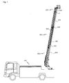
- Fig. 1 shows the structure of the high elevated ladder of fire truck in accordance with the present invention.
- Fig. 5 is a partial exploded perspective view of Fig. 3.
- the present invention presents extendable telescopic drainpipe along ladder, having a bending apparatus at the position corresponding to the hinged point of the ladder, in order to provide a drainpipe without additional joint member up to the top of the ladder.
- the extension and bending apparatus for fire truck drainpipe in accordance with the present invention is,
- the said bending apparatus is formed with hemispherical mounting groove inside the upper member and inlet hole, inside the lower part, connected with drainpipe,
- Fig. 1 shows the structure of elevated ladder for fire trucks applied with the present invention.
- An extendable ladder(200) is installed on fire truck(100), and on the side of the ladder(200) a metallic drainpipe(300) is installed.
- the said drainpipe(300) consists with multiple metallic drainpipes(301, 303, 304) of different diameters, connected telescopically for free extension and shrinking.
- the drainpipe(301) which has the largest diameter is mounted on the ladder(200) with supporting rod(302).
- At the top and bottom of the drainpipe(301) are formed with telescopic columns(305, 306) in which upper and lower drainpipes(303,304) are inserted and can slide in and out.
- the said telescopic columns(305, 306) have sealing members inside to prevent upper and lower drainpipes(303, 304) from being isolated and fire water from leaking out.
- the upper pipe(304) When the ladder(200) is being shrunk, the upper pipe(304) is inserted into the large pipe(301). When the upper pipe(304) has been inserted completely, the large pipe(301) moves downward with the ladder(200) receiving the lower pipe(303) inside.
- the upper part of the said ladder(200) can be bent with a hinge(230) for easier approach to tall buildings and control of fire water discharging point.
- the drainpipe(300) When the ladder(200) is bent, the drainpipe(300) also has to be bent at the same position with a bending apparatus(A) to enable watering at objective fire point.
- the upper part of the ladder(200) can be bent to form a bendable ladder(210) of which one side of the bending direction is coupled with the upper part of the ladder(200) with a hinge(230) so that the upper part can be bent by rotation, while the other side is joined with the cylinder rod of hydraulic cylinder(220) of which main body is joined with the opposite side of the ladder(200).
- the upper part of the drainpipe(300) has to be able to be bent at the position where the bendable ladder(210) is bent to enable watering at desired direction.
- a bending apparatus(A) is provided.
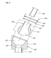
- the said bending apparatus(A) consists with fixed a member(320) and a rotating member(330). Bending is implemented by the rotation of the rotating member(33) inside the fixed member(320).
- the said fixed member(320) is formed with hemispherical mounting groove(323) inside its body where the rotating member(330) which has ball-shaped body(331) is coupled by ball-joint type.
- the said fixed member(320) is formed with an inlet(322), at the bottom of the mounting grove(323), which is connected with the exterior of the body(321).
- the upper drainpipe(304) on the lower side is joined with the bottom of the body(321) of the fixed member(320) and connected with the inlet(322) to enable the fire water coming in through the upper pipe(304) can flow into the body(321) of the fixed member.
- the body(331) of the rotating member(330) is mounted on the said mounting groove(323), having the diameter same as the inner diameter of the mounting groove(323), and formed with a pipe connection hole(332) inside.
- an outlet(333) which is extended in a certain length, as a pipe, which is formed to connect the water flow path on top of the pipe connection hole(332) of the body(331).
- the bottom of said pipe connection hole(332) has larger diameter than top, and desirably, has the diameter expanded towards the direction of bending.
- the pipe connection hole(322) can maintain connection with the inlet(322) when the rotating member(330) is bent.
- an o-ring type sealing member(324) is mounted on top of the mounting groove(323) and bottom of said holding member(325) to prevent water coming in through inlet(322) from leaking out of the fixing member body(321).
- a pipe-type outlet(333) is formed in connection with the pipe connection hole(332), inside of which is inserted with the bottom of the bending drainpipe(340), and o-ring type sealing member(334) is mounted inside the outlet(333) to prevent water from leaking.
- the bottom of the bending drainpipe(340) has a certain amount of gap to the pipe connection hole(332) which is formed on the rotating member body(331). This is because, since the upper part of the bending drainpipe(340) is fixed to the upper part of the bending ladder(210) with a bracket-type pipe fixing member(340), there should be some free space to prevent interference between the bottom of the bending drainpipe(340) and pipe connection hole(332) when the drainpipe(340) is inserted into the pipe connection hole(332) for bending, as shown in Fig. 3.
- the drainpipe(300) is shrunk according to the bending of the ladder(210) since the bottom of the upper drainpipe(304) which is connected with the bottom of the fixing member(320) is inserted into the large drainpipe(301) by a certain length.
- the fire water fed from ground comes into the inlet(322) through the lower drainpipe(310) and discharged through the pipe connection hole(332) and outlet(333), and to desired fire point through the upper drainpipe(340).
- a telescopic drainpipe is installed along with the ladder, the drainpipe can be bent in correspondence with the bending of the ladder, to extend the drainpipe up to the top of the ladder, enabling fire water discharged towards the fire point accurately maintaining the water pressure.
- the bottom of the bendable drainpipe(340) is inserted into the pipe connection hole, and at the same time, the upper drainpipe(304) is inserted into the large pipe(301) in the telescopic column(306), to enable smooth bending of the drainpipe preventing deflection or damage.
Landscapes
- Engineering & Computer Science (AREA)
- Mechanical Engineering (AREA)
- Health & Medical Sciences (AREA)
- Public Health (AREA)
- Business, Economics & Management (AREA)
- Emergency Management (AREA)
- Fire-Extinguishing By Fire Departments, And Fire-Extinguishing Equipment And Control Thereof (AREA)
- Ladders (AREA)
Abstract
This invention relates to an extension and bending apparatus for fire truck drainpipe. In more particular, by installing metallic, telescopic drainpipe along ladder arm to the top, and the drainpipe is equipped with bending apparatus at the position where the drainpipe bends, fire water can be aimed accurately at the fire point.
To this end, an extendable ladder arm is installed on fire truck, and the top of the ladder can be bent at a hinge at the angle controlled by hydraulic cylinder. A telescopic metallic drainpipe is mounted along on the ladder, having ball joint type bending device at the point where the ladder is bent as necessary, allowing fire water to be focused at fire point.
Description
- This invention relates to an extension and bending apparatus of drainpipe of fire truck. In more particular, an extension and bending apparatus for fire truck with elevated ladder of which the upper part can be bent, a drainpipe having the said extension and bending apparatus is installed along the ladder with the bendable joint at where the ladder is bent, to enable the fire water focused at the fire point.
- For fire fighting activities against fires in high apartment housings or buildings, hinged ladders are applied on fire trucks, of which upper part can be bent toward the building to aim the drainpipe at fire point and allow the ladder supported by the building exterior for stability of the ladder.
- For the elevated lader with abovementioned structure for fire trucks, as disclosed in Publication
No. 2001-26659 - However, the conventional ladders, as described above, have telescopic drainpipes from water tank on the ground up to the hinge of the ladder, but the drainpipes are not equipped with bending apparatuses. Therefore, to aim fire water to the fire point, drain tubes made with cloth have to be connected additionally.
- Such additional connecting work delays fire fighting, resulting in increase of damage by fire.
- Fig. 1 shows the structure of the high elevated ladder of fire truck in accordance with the present invention.
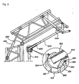
- Fig. 2 shows the bending structure of drainpipe which is one of the key parts of the invention.
- Fig. 3 shows the behavior of Fig. 2.
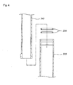
- Fig. 4 is a partial exploded perspective view of Fig. 2.
- Fig. 5 is a partial exploded perspective view of Fig. 3.
- To solve abovementioned problems, the present invention presents extendable telescopic drainpipe along ladder, having a bending apparatus at the position corresponding to the hinged point of the ladder, in order to provide a drainpipe without additional joint member up to the top of the ladder.
- The extension and bending apparatus for fire truck drainpipe in accordance with the present invention is,
- For fire trucks equipped with extendable ladder of which upper part can be bent with a hinge and the bending angle is controlled and maintained with hydraulic cylinder,
- constituted with metallic extension drainpipe installed along the ladder of fire truck, and a ball joint in the drainpipe at the position of the hinge of the ladder, and the ball joint is formed with drain water path to enable pointing of the fire water at fire point,
- and the said bending apparatus is formed with hemispherical mounting groove inside the upper member and inlet hole, inside the lower part, connected with drainpipe,
- in the said mounting groove is inserted with a spherical rotating member to allow rotation, and inside the rotating member, pipe connection hole is formed connecting the inlet of the said fixing member, and a pipe-type outlet member is formed on the upper part of the pipe connecting hole to be connected with the upper part of the drainpipe.
- The functions and their effects of the said members set forth and described hereinabove are described hereinbelow with reference to the attached drawings.
- Fig. 1 shows the structure of elevated ladder for fire trucks applied with the present invention. An extendable ladder(200) is installed on fire truck(100), and on the side of the ladder(200) a metallic drainpipe(300) is installed.
- The said drainpipe(300) consists with multiple metallic drainpipes(301, 303, 304) of different diameters, connected telescopically for free extension and shrinking.
- That is, the drainpipe(301) which has the largest diameter is mounted on the ladder(200) with supporting rod(302). At the top and bottom of the drainpipe(301) are formed with telescopic columns(305, 306) in which upper and lower drainpipes(303,304) are inserted and can slide in and out.
- The said telescopic columns(305, 306) have sealing members inside to prevent upper and lower drainpipes(303, 304) from being isolated and fire water from leaking out.
- Furthermore, by forming the diameters of the upper and lower drainpipes(303, 304) differently to allow larger pipe(301) to receive a number of smaller pipes.
- Therefore, when the ladder(200) is extended, the pipe fixed to the ladder(200) moves upward, drawing lower pipe(303) out with the telescopic column(305). When the ladder(200) is extended further after the lower pipe(303) has all been drawn out, the upper pipe(304) will be drawn out from the pipe(301) through its telescopic column(306), so that the overall length of the drainpipe(300) can keep up with the extended length of the ladder(200).
- When the ladder(200) is being shrunk, the upper pipe(304) is inserted into the large pipe(301). When the upper pipe(304) has been inserted completely, the large pipe(301) moves downward with the ladder(200) receiving the lower pipe(303) inside.
- The upper part of the said ladder(200) can be bent with a hinge(230) for easier approach to tall buildings and control of fire water discharging point.
- When the ladder(200) is bent, the drainpipe(300) also has to be bent at the same position with a bending apparatus(A) to enable watering at objective fire point.
- The structure of the bending apparatus which is one of the major advantage of the present invention is described hereinbelow, with reference to the Figures 2 and 3.
- The upper part of the ladder(200) can be bent to form a bendable ladder(210) of which one side of the bending direction is coupled with the upper part of the ladder(200) with a hinge(230) so that the upper part can be bent by rotation, while the other side is joined with the cylinder rod of hydraulic cylinder(220) of which main body is joined with the opposite side of the ladder(200).
- Therefore, the bendable ladder(210) can be bent by the extension and shrink of the hydraulic cylinder(220), as shown in Fig. 3, maintaining its bent state by the hydraulic cylinder(220).
- At this time, the upper part of the drainpipe(300) has to be able to be bent at the position where the bendable ladder(210) is bent to enable watering at desired direction. To this end, a bending apparatus(A) is provided.
- The said bending apparatus(A) consists with fixed a member(320) and a rotating member(330). Bending is implemented by the rotation of the rotating member(33) inside the fixed member(320). The said fixed member(320) is formed with hemispherical mounting groove(323) inside its body where the rotating member(330) which has ball-shaped body(331) is coupled by ball-joint type.
- The said fixed member(320) is formed with an inlet(322), at the bottom of the mounting grove(323), which is connected with the exterior of the body(321). The upper drainpipe(304) on the lower side is joined with the bottom of the body(321) of the fixed member(320) and connected with the inlet(322) to enable the fire water coming in through the upper pipe(304) can flow into the body(321) of the fixed member.
- . The body(331) of the rotating member(330) is mounted on the said mounting groove(323), having the diameter same as the inner diameter of the mounting groove(323), and formed with a pipe connection hole(332) inside.
- Furthermore, on top of the body(331) of the rotating member is formed with an outlet(333) which is extended in a certain length, as a pipe, which is formed to connect the water flow path on top of the pipe connection hole(332) of the body(331).
- Here, the bottom of said pipe connection hole(332) has larger diameter than top, and desirably, has the diameter expanded towards the direction of bending.
- Consequently, as shown in Fig. 3, the pipe connection hole(322) can maintain connection with the inlet(322) when the rotating member(330) is bent.
- The body(321) of said fixed member is formed with a holding member(325) to prevent the body(331) of the rotating member from being isolated out, and the mounting groove(323) of the fixed member body(321) is formed hemispherically to receive the rotating member body(331), preventing the rotating member(330) from being isolated by a holding member(325) joint with a bolt chain joint member(326) on top of the mounting groove(323).
- At the same time, an o-ring type sealing member(324) is mounted on top of the mounting groove(323) and bottom of said holding member(325) to prevent water coming in through inlet(322) from leaking out of the fixing member body(321).
- And, the upper part of said fixing member(321) is inclined in the direction of bending to give larger bending angle to the rotating member(330).
- On top of the rotating member body(331), a pipe-type outlet(333) is formed in connection with the pipe connection hole(332), inside of which is inserted with the bottom of the bending drainpipe(340), and o-ring type sealing member(334) is mounted inside the outlet(333) to prevent water from leaking.
- Here, it is desirable that the bottom of the bending drainpipe(340) has a certain amount of gap to the pipe connection hole(332) which is formed on the rotating member body(331). This is because, since the upper part of the bending drainpipe(340) is fixed to the upper part of the bending ladder(210) with a bracket-type pipe fixing member(340), there should be some free space to prevent interference between the bottom of the bending drainpipe(340) and pipe connection hole(332) when the drainpipe(340) is inserted into the pipe connection hole(332) for bending, as shown in Fig. 3.
- That is, the bending drainpipe(340) is inserted into the pipe connection hole(332) when the ladder is bent, at this time, if there is no free space between the bottom of the bending drainpipe(340) and bottom of the pipe connection hole(332), the bottom of the drainpipe(340) will pass through the pipe connection hole(332) and contact with the fixing member body(321), causing damage to the bending drainpipe(340) and fixing member body(321).
- Therefore, free space is necessary to avoid such damage.
- At the same time, the drainpipe(300) is shrunk according to the bending of the ladder(210) since the bottom of the upper drainpipe(304) which is connected with the bottom of the fixing member(320) is inserted into the large drainpipe(301) by a certain length.
- Consequently, the drainpipe(300) can be properly extended or shrunk with the telescopic column(306) preventing the drainpipe(300) from being bent or damaged when the ladder is bent.
- As the drainpipe(300) has a bending structure described hereinabove, the fire water fed from ground comes into the inlet(322) through the lower drainpipe(310) and discharged through the pipe connection hole(332) and outlet(333), and to desired fire point through the upper drainpipe(340).
- As described hereinabove, in the present invention, a telescopic drainpipe is installed along with the ladder, the drainpipe can be bent in correspondence with the bending of the ladder, to extend the drainpipe up to the top of the ladder, enabling fire water discharged towards the fire point accurately maintaining the water pressure. Especially, when the ladder is bent, at the bending part of the drainpipe which has different position of rotating radius from that of the hinge axis of the ladder, the bottom of the bendable drainpipe(340) is inserted into the pipe connection hole, and at the same time, the upper drainpipe(304) is inserted into the large pipe(301) in the telescopic column(306), to enable smooth bending of the drainpipe preventing deflection or damage.
Claims (5)
- For a fire truck installed with extendable ladder of which the upper part can be bent with hinge, and the bending angle can be controlled and maintained with hydraulic cylinder,
An extension and bending apparatus for fire truck drainpipe which is characterized by, telescopic metallic pipe mounted on said ladder, having a ball-joint-type bending apparatus corresponding to the position of the bending of the ladder, providing fire water path inside the bending apparatus to enable water discharging at desired direction. - The extension and bending apparatus for fire truck drainpipe in accordance with the Claim 1, wherein the bending apparatus is characterized by,
Being formed with a fixing member body which is formed with hemispherical mounting groove inside, and an inlet is formed at the bottom of said groove connecting with the lower drainpipe,
And said mounting groove is inserted with a ball-joint-type rotating member body to provide rotational joint, and inside of the rotating member body is formed a pipe connection hole which is connected with the inlet of said fixing member body, and a pipe-type outlet is formed on top of the pipe connection hole to be connected with the upper drainpipe. - The extension and bending apparatus for fire truck drainpipe in accordance with the Claim 2, wherein the mounting groove is characterized by having a ring-type holding member is joint with a connecting member, on top of the groove, to prevent rotating member body from being isolated.
- The extension and bending apparatus for fire truck drainpipe in accordance with the Claim 2, wherein the extension and bending apparatus are characterized by having sealing members between the bodies of the fixing member and rotating member, and between the outlet and upper drainpipe.
- The extension and bending apparatus for fire truck drainpipe in accordance with the Claim 2, wherein the pipe connection hole formed in the body of the rotating member is characterized by having larger diameter at its bottom than its top.
Applications Claiming Priority (1)
| Application Number | Priority Date | Filing Date | Title |
|---|---|---|---|
| KR1020060078520A KR100769861B1 (en) | 2006-08-21 | 2006-08-21 | Construction and Refraction of Fire Truck Waterproof Pipes |
Publications (1)
| Publication Number | Publication Date |
|---|---|
| EP1892017A2 true EP1892017A2 (en) | 2008-02-27 |
Family
ID=38649968
Family Applications (1)
| Application Number | Title | Priority Date | Filing Date |
|---|---|---|---|
| EP07015309A Withdrawn EP1892017A2 (en) | 2006-08-21 | 2007-08-03 | Extension and bending apparatus for fire truck drainpipe |
Country Status (3)
| Country | Link |
|---|---|
| EP (1) | EP1892017A2 (en) |
| JP (1) | JP2008049163A (en) |
| KR (1) | KR100769861B1 (en) |
Cited By (6)
| Publication number | Priority date | Publication date | Assignee | Title |
|---|---|---|---|---|
| CN102777128A (en) * | 2012-08-14 | 2012-11-14 | 连云港黄海机械股份有限公司 | Folding boring tower |
| CN114887263A (en) * | 2022-04-20 | 2022-08-12 | 湖南宏迅消防安全工程有限公司 | Fire-fighting rescue auxiliary system |
| DE102022105086A1 (en) | 2022-03-03 | 2023-09-07 | Rosenbauer International Ag | Extendable ladder set with several ladder sections |
| DE102022105087A1 (en) | 2022-03-03 | 2023-09-07 | Rosenbauer International Ag | Lifting unit with a telescopic extension arm and a clamping device |
| DE102022109721A1 (en) | 2022-04-22 | 2023-10-26 | Rosenbauer International Ag | Method for forming a supply line for supplying an extinguishing agent to a set of conductors and a set of conductors with a supply line |
| IT202200010415A1 (en) * | 2022-05-19 | 2023-11-19 | Magirus Gmbh | IMPROVED TELESCOPIC LADDER ASSEMBLY FOR A FIRE VEHICLE |
Families Citing this family (1)
| Publication number | Priority date | Publication date | Assignee | Title |
|---|---|---|---|---|
| KR101686188B1 (en) * | 2015-04-28 | 2016-12-28 | (주)화담알앤알 | Automatic firefighting monitor |
Family Cites Families (8)
| Publication number | Priority date | Publication date | Assignee | Title |
|---|---|---|---|---|
| JPS6344633Y2 (en) * | 1980-10-18 | 1988-11-18 | ||
| JPS62115500U (en) * | 1986-01-16 | 1987-07-22 | ||
| JPH04343859A (en) * | 1991-05-21 | 1992-11-30 | Nohmi Bosai Ltd | Piping for sprinkler type extinguishing equipment |
| JPH08159348A (en) * | 1994-12-09 | 1996-06-21 | U Ii Jiyointo Kk | Ball joint |
| JPH10281370A (en) * | 1997-04-09 | 1998-10-23 | Suido Gijutsu Kaihatsu Kiko:Kk | Telescopic rocking pipe fittings |
| KR100259932B1 (en) * | 1998-02-21 | 2000-06-15 | 이학원 | Apparatus discharging water of fire pump car with ladder |
| US6808025B2 (en) | 1999-09-10 | 2004-10-26 | Schwing America, Inc. | Fire-fighting system having improved flow |
| KR100597577B1 (en) * | 2004-10-07 | 2006-07-06 | 주식회사 한우티엔씨 | Fire prevention water pipe device for ladder fire truck |
-
2006
- 2006-08-21 KR KR1020060078520A patent/KR100769861B1/en not_active Expired - Fee Related
-
2007
- 2007-08-03 EP EP07015309A patent/EP1892017A2/en not_active Withdrawn
- 2007-08-20 JP JP2007214079A patent/JP2008049163A/en active Pending
Cited By (11)
| Publication number | Priority date | Publication date | Assignee | Title |
|---|---|---|---|---|
| CN102777128A (en) * | 2012-08-14 | 2012-11-14 | 连云港黄海机械股份有限公司 | Folding boring tower |
| CN102777128B (en) * | 2012-08-14 | 2014-12-03 | 连云港黄海机械股份有限公司 | Folding boring tower |
| DE102022105086A1 (en) | 2022-03-03 | 2023-09-07 | Rosenbauer International Ag | Extendable ladder set with several ladder sections |
| DE102022105087A1 (en) | 2022-03-03 | 2023-09-07 | Rosenbauer International Ag | Lifting unit with a telescopic extension arm and a clamping device |
| WO2023164736A1 (en) | 2022-03-03 | 2023-09-07 | Rosenbauer International Ag | Extendable ladder set with a plurality of ladder parts |
| WO2023164737A1 (en) | 2022-03-03 | 2023-09-07 | Rosenbauer International Ag | Lifting unit comprising a boom arm which is telescopic and comprising a loading device |
| CN114887263A (en) * | 2022-04-20 | 2022-08-12 | 湖南宏迅消防安全工程有限公司 | Fire-fighting rescue auxiliary system |
| CN114887263B (en) * | 2022-04-20 | 2023-01-20 | 湖南宏迅消防安全工程有限公司 | Fire-fighting rescue auxiliary system |
| DE102022109721A1 (en) | 2022-04-22 | 2023-10-26 | Rosenbauer International Ag | Method for forming a supply line for supplying an extinguishing agent to a set of conductors and a set of conductors with a supply line |
| IT202200010415A1 (en) * | 2022-05-19 | 2023-11-19 | Magirus Gmbh | IMPROVED TELESCOPIC LADDER ASSEMBLY FOR A FIRE VEHICLE |
| EP4279703A1 (en) * | 2022-05-19 | 2023-11-22 | Magirus GmbH | Improved ladder assembly for a firefighting vehicle |
Also Published As
| Publication number | Publication date |
|---|---|
| KR100769861B1 (en) | 2007-10-24 |
| JP2008049163A (en) | 2008-03-06 |
Similar Documents
| Publication | Publication Date | Title |
|---|---|---|
| EP1892017A2 (en) | Extension and bending apparatus for fire truck drainpipe | |
| US9920868B2 (en) | Extendable stand pipe and flex joint modules | |
| US8534370B1 (en) | Roof mounted remotely controlled fire fighting tower | |
| KR102195579B1 (en) | angle type dry pendant sprinkler head | |
| EP2716369A1 (en) | Misting apparatus and sprinkling device thereof | |
| CN102500082A (en) | Water pipeline connecting structure for fire truck and fire truck with same | |
| KR20210001309A (en) | Elbow assembly | |
| KR100435300B1 (en) | Structure of fixing sprinkler to ceiling | |
| CN219606152U (en) | PE pipe pressure relief device | |
| KR20170075685A (en) | Tie rod connector for fire fighting springkler system | |
| CN116792053B (en) | Underground coal mine drilling blowout preventer | |
| CN206026906U (en) | Desulfurization absorption tower fire prevention device that disappears | |
| KR102729363B1 (en) | Dry Typed Sprinkler For Fire Fighting | |
| JPH05137810A (en) | Unwinding tube for sprinkler | |
| US20050242573A1 (en) | Hose weight with ballast | |
| KR102664350B1 (en) | End hose holder of distribution boom of concrete pump, concrete pump having end hose holder, and method of mounting the end hose holder | |
| KR100597577B1 (en) | Fire prevention water pipe device for ladder fire truck | |
| KR200418491Y1 (en) | Link pipe structure with cylindrical pipe | |
| CN204056257U (en) | Compound type damages pipe bracket | |
| CN209797321U (en) | Anti-corrosion device and standard knot comprising same | |
| CN214248611U (en) | Pipeline installation mechanism for construction of fire-fighting equipment engineering | |
| KR102650240B1 (en) | Fence connector | |
| CN205727776U (en) | A kind of spraying machine | |
| KR102719560B1 (en) | Piping protection saftey net structure | |
| JP3142364U (en) | Sprinkler mounting structure |
Legal Events
| Date | Code | Title | Description |
|---|---|---|---|
| PUAI | Public reference made under article 153(3) epc to a published international application that has entered the european phase |
Free format text: ORIGINAL CODE: 0009012 |
|
| 17P | Request for examination filed |
Effective date: 20070803 |
|
| AK | Designated contracting states |
Kind code of ref document: A2 Designated state(s): AT BE BG CH CY CZ DE DK EE ES FI FR GB GR HU IE IS IT LI LT LU LV MC MT NL PL PT RO SE SI SK TR |
|
| AX | Request for extension of the european patent |
Extension state: AL BA HR MK YU |
|
| STAA | Information on the status of an ep patent application or granted ep patent |
Free format text: STATUS: THE APPLICATION IS DEEMED TO BE WITHDRAWN |
|
| 18D | Application deemed to be withdrawn |
Effective date: 20100302 |