EP1892011A2 - Electromedical implant - Google Patents
Electromedical implant Download PDFInfo
- Publication number
- EP1892011A2 EP1892011A2 EP07014652A EP07014652A EP1892011A2 EP 1892011 A2 EP1892011 A2 EP 1892011A2 EP 07014652 A EP07014652 A EP 07014652A EP 07014652 A EP07014652 A EP 07014652A EP 1892011 A2 EP1892011 A2 EP 1892011A2
- Authority
- EP
- European Patent Office
- Prior art keywords
- signal
- wake
- control unit
- transceiver
- transmission
- Prior art date
- Legal status (The legal status is an assumption and is not a legal conclusion. Google has not performed a legal analysis and makes no representation as to the accuracy of the status listed.)
- Granted
Links
Images


Classifications
-
- A—HUMAN NECESSITIES
- A61—MEDICAL OR VETERINARY SCIENCE; HYGIENE
- A61N—ELECTROTHERAPY; MAGNETOTHERAPY; RADIATION THERAPY; ULTRASOUND THERAPY
- A61N1/00—Electrotherapy; Circuits therefor
- A61N1/18—Applying electric currents by contact electrodes
- A61N1/32—Applying electric currents by contact electrodes alternating or intermittent currents
- A61N1/36—Applying electric currents by contact electrodes alternating or intermittent currents for stimulation
- A61N1/372—Arrangements in connection with the implantation of stimulators
- A61N1/37211—Means for communicating with stimulators
- A61N1/37252—Details of algorithms or data aspects of communication system, e.g. handshaking, transmitting specific data or segmenting data
- A61N1/37276—Details of algorithms or data aspects of communication system, e.g. handshaking, transmitting specific data or segmenting data characterised by means for reducing power consumption during telemetry
-
- A—HUMAN NECESSITIES
- A61—MEDICAL OR VETERINARY SCIENCE; HYGIENE
- A61N—ELECTROTHERAPY; MAGNETOTHERAPY; RADIATION THERAPY; ULTRASOUND THERAPY
- A61N1/00—Electrotherapy; Circuits therefor
- A61N1/18—Applying electric currents by contact electrodes
- A61N1/32—Applying electric currents by contact electrodes alternating or intermittent currents
- A61N1/36—Applying electric currents by contact electrodes alternating or intermittent currents for stimulation
- A61N1/372—Arrangements in connection with the implantation of stimulators
- A61N1/37211—Means for communicating with stimulators
- A61N1/37252—Details of algorithms or data aspects of communication system, e.g. handshaking, transmitting specific data or segmenting data
- A61N1/37288—Communication to several implantable medical devices within one patient
Definitions
- the invention relates to an implantable medical device having a built-in transceiver for wirelessly transmitting and receiving data that can be disabled between individual data transmissions.
- Such implantable medical devices may be, for example, pacemakers or cardioverter / defibrillators or combinations of both.
- a variety of such implants are known, which have a transmitter / receiver, ie a transceiver, with the help of which it is possible to transfer physiological or technical data or both from the implant to an external device or vice versa using an external device data for Implant to transfer.
- the latter may be desirable, for example, for programming the implant or else to query specific data.
- multiple implants may be within range of one another or within range of one or more external devices.
- the object of the invention is to provide an implant which is suitable for the aforementioned scenario and as energy-saving as possible.
- an implant of the type mentioned above which has a waking unit in addition to the transceiver, which is adapted to the transceiver from its idle state or from its off state in which it requires little or no energy in its fully operational State in which he needs more energy.
- the wake-up unit has a second, separate low-power receiver which has a significantly lower energy requirement than the transceiver in its switched-on or fully operational state.
- the wake-up unit has a wake-up control unit which is connected to an output of the low power receiver.
- the low-power receiver is designed to monitor a plurality of predetermined frequency ranges such that it generates an output signal in the event of a transmission of sufficient signal strength in one or more of the frequency ranges and outputs it to the wake-up control unit.
- the wake-up control unit is designed to evaluate output signals of the low-power receiver and to output a wake-up signal to the transceiver, which switches this on or fully operational, if a predetermined condition is fulfilled or a plurality of predetermined conditions are met.
- the wake-up control unit is designed such that it emits a wake-up signal to the transceiver when the low-power receiver emits a series of output signals which indicate that the low-power receiver has detected a sequence of transmissions of sufficient signal strength in different frequency ranges, which correspond to a given sequence or sequence.
- the predetermined sequence may be such that the output signals indicate transmissions in the frequency ranges C, A, B, D (in that order).
- Such a sequence of transmissions in different frequency ranges is also referred to below as a trigger signal sequence, since such a sequence of transmissions is intended to trigger the switching on of the transceiver.
- the order of the output signals of the low power receiver thus always characterizes a respective frequency scheme.
- a frequency scheme serves as a kind of key for switching on the transceiver of a corresponding preset or programmed implant.
- the low-power receiver preferably has a plurality of band-pass filters whose passband is adapted to the predetermined frequency ranges. Associated with each bandpass filter is a signal detector cooperating with the respective bandpass filter such that the signal detector outputs a signal when the low power receiver in a respective frequency range corresponding to a passband of the bandpass filter to which the signal detector is assigned transmits with sufficient signal strength receives.
- a low power receiver is at the output of a respective signal detector before an output signal for transmission to the wake-up control unit, as soon as the low power receiver receives a transmission of sufficient signal strength in the respective frequency range. In this way, the low power receiver generates signals or signal sequences which are to be further processed by the wake-up control unit.
- the wake-up control unit is designed to detect the sequence of the signals output by the signal detectors and to compare them with a predetermined sequence in order to deliver the wake-up signal to the transceiver in the case of a positive comparison (the received signal sequence corresponds to the predetermined order).
- the wake-up control unit may have a time monitoring unit and be designed to generate the wake-up signal only if the signals output by the signal detectors occur in succession within a predetermined period of time.
- the predetermined period of time can be a total period of time within which all signals must have occurred and it can also be given a plurality of time periods that describe until when a subsequent signal must follow the respective preceding signal.
- the transceiver can be switched by receiving a trigger signal sequence of a switched off or a power-saving mode in an on or fully operational mode, without the need to receive a signal with sufficiently good quality to the signal to be able to decode. Therefore, a simple receiver is sufficient as a low power receiver with low energy consumption. Nevertheless, a targeted response of a corresponding preset implant is possible, even without that first, for example, corresponding address data in a received signal must be decoded and evaluated.
- Another aspect relates to the reaction of the implant to the receipt of a trigger signal or a trigger signal sequence. If, for example, a plurality of implants is addressed simultaneously by a trigger signal sequence, this could result in all of the implants addressed simultaneously emitting a response signal to the carrier signal sequence, so that successful communication with an external device is not possible, at least for the majority of the implants.
- the implantable medical device preferably has a transmission control unit which has a random generator or is connected to it and is designed to emit a response signal after expiry of a waiting time after the transceiver is switched on by the wake-up control unit and, at the same time, the time a transmission start after switching on the transceiver by the wake-up control unit to determine such that the time of the transmission start corresponds to the end time of the waiting time, which in turn begins with the wake-up signal.
- the waiting time has a duration which corresponds to the product ZZ x SD from a random number ZZ generated by the random number generator and a predetermined, average transmission duration SD.
- the waiting time after which an implant responds to a corresponding trigger signal has a random length, so that it is unlikely that two implants respond to a trigger signal at the same time.
- the random number is scaled to be an integer between 0 and a maximum number of expected implants in the receiving range of an external device minus 1, it is very unlikely that during the transmission duration for the transmission of the response signal of a first implant, a second implant begins to transmit a response signal.
- this time period SD determines a timeslot for the transmission of the response signal. Since all implants in the environment of the external device are woken up by the same trigger signal on the part of the external device or, in a more general embodiment, are at least synchronized, the timeslots, that is to say the transmission end times SD connected in series depending on the respective random number ZZ, are equally clocked.
- the transmission control unit is designed in a preferred embodiment, to repeat the transmission of the response signal after a re-determined waiting time.
- the repetition of the transmission of the response signal may be dependent on whether a respective transmitted response signal remains unanswered or not.
- FIG. 1 shows an external device as an external transceiver 10 and two implants 20 'and 20 ", which are located within a reception range of the external device 10 indicated by a dashed line 12.
- the reception range results from the transmission power of the implants 20'. and 20 "and the sensitivity of the receiver of the external device 10.
- the implants each have a transceiver 203 (see FIG. 2) which consumes relatively much energy in the transmit and receive mode and therefore as long as possible and as often as possible in one Energy saving mode should be kept or switched off, but at the same time should be switched to its fully operational mode by a signal from outside the implant. However, this should not happen by signals that come from another implant or completely foreign transmitting device in the receiving range of each device, if possible. If possible, the transceiver 203 of a respective implant should be woken up only by an external device such as the external device 10 as possible.
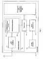
- the implant 20 depicted in FIG. 2 represents a preferred embodiment of an implant which takes into account both of the aforementioned problems.
- the implant 20 has a wake-up unit 202, which is connected to the transceiver 203 of the implant 20 and can output to the transceiver 203 a wake-up signal, by which the transceiver 203 of FIG a switched-off state or a power-saving mode can be switched to a more power-consuming, fully operational mode.
- the wake-up signal which the wake-up unit 202 outputs to the transceiver 203, should be able to be triggered wirelessly, but not by any data transmission.
- the reception of the wake-up signal triggering wirelessly transmitting trigger signal should not require as much power as the transceiver requires in 203 in its fully operational state.
- the wake-up unit 202 comprises, in addition to a wake-up control unit 207, which finally generates the wake-up signal, a low power receiver 210, which as a broadband receiver is capable of detecting wireless transmissions of signals in different frequency ranges.
- the low power receiver 210 is capable of detecting transmissions each exceeding a predetermined minimum signal strength in one of a plurality of predetermined frequency ranges and producing an output signal each if it is transmitting in one of the predetermined frequency ranges with a signal strength detected above the predetermined minimum.
- the low-power receiver (see FIG. 3) has four band-pass filters 211 ', 211 ", 211"' and 211 "", which each have a pass band (pass band) which is tuned to a frequency range of four frequency ranges.
- Each bandpass filter 211 ', 211 ", 211"' and 211 "” is followed in each case by a signal detector 212 ', 213', 212 “, 213", 212 "', 213”', 212 "", 213 "”.
- Each of these signal detectors includes a threshold switch 212 ', 212 “, 212'” and 212 “" responsive to output signal strength at the output of correspondingly associated bandpass filter 211 ', 211 ", 211"' or 211 “” is present, which is above the predetermined threshold.
- the respective threshold switch 212 ', 212 “, 212'” or 212 “” responds to such a signal, it triggers a respective one of the threshold switches 212 ', 212 “, 212'” or 212 “” downstream monostable multivibrator 213 ', 213 “, 213"' or 213 “” out.
- the respective monostable multivibrator 213 ', 213 “, 213”' or 213 “” generates in this way an output signal which indicates that in the above the passband of the respective bandpass filter 211 ', 211 ", 211"' or 211 " Frequency range has taken place a transmission of signals with a signal strength above the predetermined minimum.
- the output signals of the monostable multivibrators 213 ', 213 “, 213”' and 213 "" which are simultaneously output signals of the low power receiver 210, by their order the order in which the transmissions in different frequency ranges by the low power receiver 210 are received.
- the wake-up control unit 206 is designed to evaluate the output signals of the low-power receiver 210 in two ways.
- the wake-up control unit is designed to compare the order of the output signals of the low-power receiver 210 with a predetermined sequence and to output the wake-up signal to the transceiver 203 only if the order of the output signals of the low-power receiver 210 of the predefined, in the Implant 20 stored order corresponds.
- the wake-up control unit 206 is configured to ensure, with the aid of a time monitoring unit 207, that the wake-up signal is only generated if the output signals of the low-power receiver 210 follow each other not only in the predetermined sequence but also within the respective predetermined time arrive.
- the predetermined order of the signals and the corresponding predetermined times result in a kind of characteristic key with which, for example, an external device can wirelessly wake up a transceiver 203 of an implant 20 without data having to be decoded and evaluated, for example, as address data in a wirelessly transmitted signal could be included.
- a transmission control unit 204 of the implant 20 is designed to control the transmission of a response signal which the implant 20 emits after receiving a wirelessly transmitted trigger signal which has led via a corresponding wake-up signal to wake up the transceiver 203.
- the transmission control unit is configured to trigger a transmission of the response signal via the transceiver 203 only after expiration of a waiting time, which begins with the waking up of the transceiver 203.
- the transmission control unit 204 calculates this waiting time from a random number ZZ generated by a random generator 205 and a predetermined maximum value for a transmission duration SD for transmitting the response signal B from a likewise predetermined integer AI, which is greater than the maximum number of implants to be expected the range of an external device.
- the waiting time is a product of the integer ZZ and SD: ZZ x SD scaled with AI.
- the respective, so determined waiting time is started upon receipt of the carrier signal and causes the control unit 204 triggers the transmission of the response signal via the receiver 203 at the end of the waiting time.
Landscapes
- Health & Medical Sciences (AREA)
- Animal Behavior & Ethology (AREA)
- Biomedical Technology (AREA)
- Nuclear Medicine, Radiotherapy & Molecular Imaging (AREA)
- Radiology & Medical Imaging (AREA)
- Life Sciences & Earth Sciences (AREA)
- Engineering & Computer Science (AREA)
- General Health & Medical Sciences (AREA)
- Public Health (AREA)
- Veterinary Medicine (AREA)
- Mobile Radio Communication Systems (AREA)
- Measuring And Recording Apparatus For Diagnosis (AREA)
- Electrotherapy Devices (AREA)
Abstract
Description
Die Erfindung betrifft ein implantierbares medizinisches Gerät mit einem eingebauten Sender/Empfänger (Transceiver) zum drahtlosen Senden und Empfangen von Daten, die zwischen einzelnen Datenübertragungen abgeschaltet werden kann.The invention relates to an implantable medical device having a built-in transceiver for wirelessly transmitting and receiving data that can be disabled between individual data transmissions.
Solche implantierbaren medizinischen Geräte können beispielsweise Herzschrittmacher oder Kardioverter/Defibrillatoren oder Kombinationen aus beiden sein. Mittlerweile sind eine Vielzahl solcher Implantate bekannt, die einen Sender/Empfänger, also eine Transceiver aufweisen, mit dessen Hilfe es möglich ist, physiologische oder technische Daten oder beides aus dem Implantat auf ein externes Gerät zu übertragen oder umgekehrt mit Hilfe eines externen Gerätes Daten zum Implantat zu übertragen. Letzteres kann beispielsweise zur Programmierung des Implantates oder aber auch zur Abfrage bestimmter Daten wünschenswert sein.Such implantable medical devices may be, for example, pacemakers or cardioverter / defibrillators or combinations of both. Meanwhile, a variety of such implants are known, which have a transmitter / receiver, ie a transceiver, with the help of which it is possible to transfer physiological or technical data or both from the implant to an external device or vice versa using an external device data for Implant to transfer. The latter may be desirable, for example, for programming the implant or else to query specific data.
Grundsätzlich stellt sich bei solchen Implantaten immer das Problem, dass die Energieressourcen des Implantats begrenzt sind und meist durch eine fest in das Implantat eingebaute Batterie gegeben sind. Es besteht daher grundsätzlich die Aufgabe, den Energieverbrauch des Implantats möglichst zu beschränken. Dies kann beispielsweise dadurch geschehen, dass momentan nicht gebrauchte Bestandteile des Implantats abgeschaltet werden. In diesem Falle stellt sich das weitere Problem, wie ein Wiedereinschalten dieser Implantatteile erfolgen soll.In principle, such implants always pose the problem that the energy resources of the implant are limited and are usually given by a battery permanently installed in the implant. There is therefore basically the task of limiting the energy consumption of the implant as possible. This can be done, for example, by switching off unused components of the implant at the moment. In this case, the further problem arises as to how to turn these implant parts on again.
Darüber hinaus ist zu berücksichtigen, dass sich gegebenenfalls mehrere Implantate in gegenseitiger Reichweite befinden oder in Reichweite eines oder mehrere externer Geräte.It should also be noted that multiple implants may be within range of one another or within range of one or more external devices.
Aufgabe der Erfindung ist es, ein Implantat zu schaffen, das für das zuvor genannte Szenario tauglich und dabei möglichst energiesparend ist.The object of the invention is to provide an implant which is suitable for the aforementioned scenario and as energy-saving as possible.
Erfindungsgemäß wird diese Aufgabe durch ein Implantat der eingangs genannten Art gelöst, das neben dem Transceiver eine Aufweckeinheit aufweist, die dazu ausgebildet ist, den Transceiver aus seinem Ruhezustand oder aus seinem ausgeschalteten Zustand, in dem er wenig oder keine Energie benötigt, in seinen voll betriebsbereiten Zustand zu schalten, in dem er entsprechend mehr Energie benötigt. Hierzu weist die Aufweckeinheit einen zweiten, separaten Low Power Empfänger auf, der einen wesentlich geringeren Energiebedarf hat als der Transceiver in seinem eingeschalteten bzw. voll betriebsbereiten Zustand. Außerdem weist die Aufweckeinheit eine Aufweck-Steuereinheit auf, die mit einem Ausgang des Low Power Empfängers verbunden ist. Der Low Power Empfänger ist ausgebildet, eine Mehrzahl vorgegebener Frequenzbereiche derart zu überwachen, dass er im Falle einer Übertragung ausreichender Signalstärke in einem oder mehreren der Frequenzbereiche ein Ausgangssignal erzeugt und an die Aufweck-Steuereinheit abgibt. Die Aufweck-Steuereinheit ist ausgebildet, Ausgangssignale des Low Power Empfängers auszuwerten und ein Aufwecksignal an den Transceiver abzugeben, der diesen ein- oder voll betriebsbereit schaltet, falls eine vorgegebene Bedingung erfüllt ist oder eine Mehrzahl vorgegebener Bedingungen erfüllt sind. Dabei ist die Aufweck-Steuereinheit so ausgebildet, dass sie dann ein Aufwecksignal an den Transceiver abgibt, wenn der Low Power Empfänger eine Folge von Ausgangssignalen abgibt, die kennzeichnen, dass der Low Power Empfänger eine Folge von Übertragungen ausreichender Signalstärke in verschiedenen Frequenzbereichen erfasst hat, die einer vorgegebenen Abfolge oder Reihenfolge entsprechen. Wenn die von dem Low Power Empfänger überwachten Frequenzbereiche beispielsweise die Frequenzbereiche A, B, C und D sind, kann die vorgegebene Abfolge bzw. Reihenfolge derart sein, dass die Ausgangssignale Übertragungen in den Frequenzbereichen C, A, B, D (in dieser Reihenfolge) kennzeichnen.According to the invention, this object is achieved by an implant of the type mentioned above, which has a waking unit in addition to the transceiver, which is adapted to the transceiver from its idle state or from its off state in which it requires little or no energy in its fully operational State in which he needs more energy. For this purpose, the wake-up unit has a second, separate low-power receiver which has a significantly lower energy requirement than the transceiver in its switched-on or fully operational state. In addition, the wake-up unit has a wake-up control unit which is connected to an output of the low power receiver. The low-power receiver is designed to monitor a plurality of predetermined frequency ranges such that it generates an output signal in the event of a transmission of sufficient signal strength in one or more of the frequency ranges and outputs it to the wake-up control unit. The wake-up control unit is designed to evaluate output signals of the low-power receiver and to output a wake-up signal to the transceiver, which switches this on or fully operational, if a predetermined condition is fulfilled or a plurality of predetermined conditions are met. In this case, the wake-up control unit is designed such that it emits a wake-up signal to the transceiver when the low-power receiver emits a series of output signals which indicate that the low-power receiver has detected a sequence of transmissions of sufficient signal strength in different frequency ranges, which correspond to a given sequence or sequence. For example, if the frequency ranges monitored by the low power receiver are the frequency ranges A, B, C and D, the predetermined sequence may be such that the output signals indicate transmissions in the frequency ranges C, A, B, D (in that order).
Eine derartige Abfolge von Übertragungen in verschiedenen Frequenzbereichen soll im Folgenden auch als Triggersignalfolge bezeichnet werden, da eine derartige Folge von Übertragungen dazu dienen soll, das Einschalten des Transceivers auszulösen. Die Reihenfolge der Ausgangssignale des Low Power Empfängers kennzeichnet somit immer ein jeweiliges Frequenzschema. Ein Frequenzschema dient quasi als Schlüssel für das Einschalten des Transceivers eines entsprechend voreingestellten oder programmierten Implantats.Such a sequence of transmissions in different frequency ranges is also referred to below as a trigger signal sequence, since such a sequence of transmissions is intended to trigger the switching on of the transceiver. The order of the output signals of the low power receiver thus always characterizes a respective frequency scheme. A frequency scheme serves as a kind of key for switching on the transceiver of a corresponding preset or programmed implant.
Ergänzend oder auch ersatzweise zu der Vorgabe einer Reihenfolge, also eines Frequenzschemas, können auch einzelne Zeiten vorgegeben sein, zu denen die Signale aufeinander folgen müssen. Bei der ersatzweisen Vorgabe der Reihenfolge kann beispielsweise die Aufweckeinheit allein die zeitliche Abfolge von Signalen auf nur einem Frequenzband überwachen.In addition or as a substitute to the specification of an order, that is to say of a frequency scheme, it is also possible to specify individual times at which the signals must follow one another. For example, with the replacement of the order, the waking unit alone can monitor the time sequence of signals on only one frequency band.
Zum vorgenannten Zweck weist der Low Power Empfänger vorzugsweise mehrere Bandpassfilter auf, deren Durchlassbereich an die vorgegebenen Frequenzbereiche angepasst ist. Jedem Bandpassfilter ist ein Signaldetektor zugeordnet, der derart mit dem jeweiligen Bandpassfilter zusammenwirkt, dass der Signaldetektor ein Signal ausgibt, wenn der Low Power Empfänger in einem jeweiligen Frequenzbereich, der einem Durchlassbereich desjenigen Bandfilters entspricht, dem der Signaldetektor zugeordnet ist, eine Übertragung mit ausreichender Signalstärke empfängt. Bei einem derartigen Low Power Empfänger liegt am Ausgang eines jeweiligen Signaldetektors ein Ausgangssignal zur Weitergabe an die Aufweck-Steuereinheit vor, sobald der Low Power Empfänger eine Übertragung ausreichender Signalstärke im jeweiligen Frequenzbereich empfängt. Auf diese Weise erzeugt der Low Power Empfänger Signale bzw. Signalfolgen, die von der Aufweck-Steuereinheit weiterzuverarbeiten sind.For the aforementioned purpose, the low-power receiver preferably has a plurality of band-pass filters whose passband is adapted to the predetermined frequency ranges. Associated with each bandpass filter is a signal detector cooperating with the respective bandpass filter such that the signal detector outputs a signal when the low power receiver in a respective frequency range corresponding to a passband of the bandpass filter to which the signal detector is assigned transmits with sufficient signal strength receives. In such a low power receiver is at the output of a respective signal detector before an output signal for transmission to the wake-up control unit, as soon as the low power receiver receives a transmission of sufficient signal strength in the respective frequency range. In this way, the low power receiver generates signals or signal sequences which are to be further processed by the wake-up control unit.
Vorzugsweise ist die Aufweck-Steuereinheit ausgebildet, die Reihenfolge der von den Signaldetektoren ausgegebenen Signale zu erfassen und mit einer vorgegebenen Reihenfolge zu vergleichen, um im Falle eines positiven Vergleichs (die empfangene Signalfolge entspricht der vorgegebenen Reihenfolge) das Aufwecksignal an den Transceiver abzugeben.Preferably, the wake-up control unit is designed to detect the sequence of the signals output by the signal detectors and to compare them with a predetermined sequence in order to deliver the wake-up signal to the transceiver in the case of a positive comparison (the received signal sequence corresponds to the predetermined order).
Zusätzlich kann die Aufweck-Steuereinheit eine Zeitüberwachungseinheit aufweisen und ausgebildet sein, das Aufwecksignal nur dann zu erzeugen, wenn die von den Signaldetektoren ausgegebenen Signale innerhalb einer vorgegebenen Zeitdauer nacheinander auftreten. Die vorgegebene Zeitdauer kann dabei eine Gesamtzeitdauer sein, innerhalb der alle Signale aufgetreten sein müssen und es können auch mehrere Zeitdauern vorgegeben sein, die beschreiben, bis wann ein nachfolgendes Signal auf das jeweils vorangehende Signal folgen muss.In addition, the wake-up control unit may have a time monitoring unit and be designed to generate the wake-up signal only if the signals output by the signal detectors occur in succession within a predetermined period of time. The predetermined period of time can be a total period of time within which all signals must have occurred and it can also be given a plurality of time periods that describe until when a subsequent signal must follow the respective preceding signal.
In allen Ausführungsvarianten ergibt sich ein implantierbares medizinisches Gerät, dessen Transceiver durch Empfangen einer Triggersignalfolge von einem ausgeschaltetem oder einem Stromsparmodus in einen eingeschalteten bzw. voll betriebsbereiten Modus geschaltet werden kann, ohne dass dazu ein Signal mit ausreichend guter Qualität empfangen werden muss, um das Signal dekodieren zu können. Daher reicht ein einfacher Empfänger als Low Power Empfänger mit geringem Energiebedarf. Dennoch ist ein gezieltes Ansprechen eines entsprechend voreingestellten Implantats möglich, auch ohne dass dafür zunächst beispielsweise entsprechende Adressdaten in einem empfangenen Signal dekodiert und ausgewertet werden müssen.In all embodiments, there is an implantable medical device, the transceiver can be switched by receiving a trigger signal sequence of a switched off or a power-saving mode in an on or fully operational mode, without the need to receive a signal with sufficiently good quality to the signal to be able to decode. Therefore, a simple receiver is sufficient as a low power receiver with low energy consumption. Nevertheless, a targeted response of a corresponding preset implant is possible, even without that first, for example, corresponding address data in a received signal must be decoded and evaluated.
Ein weiterer Aspekt betrifft die Reaktion des Implantats auf den Empfang eines Triggersignals bzw. einer Triggersignalfolge. Wenn beispielsweise eine Mehrzahl von Implantaten durch eine Triggersignalfolge gleichzeitig angesprochen wird, könnte dies zur Folge haben, dass alle angesprochenen Implantate gleichzeitig ein Antwortsignal auf die Trägersignalfolge aussenden, so dass wenigstens für die Mehrzahl der Implantate eine erfolgreiche Kommunikation mit einem externen Gerät nicht möglich ist.Another aspect relates to the reaction of the implant to the receipt of a trigger signal or a trigger signal sequence. If, for example, a plurality of implants is addressed simultaneously by a trigger signal sequence, this could result in all of the implants addressed simultaneously emitting a response signal to the carrier signal sequence, so that successful communication with an external device is not possible, at least for the majority of the implants.
Um diesem Problem zu begegnen, weist das implantierbare medizinische Gerät vorzugsweise eine Sendesteuereinheit auf, die einen Zufallsgenerator aufweist oder mit einem solchen verbunden und ausgebildet ist, nach Ablauf einer Wartezeit nach dem Einschalten des Transceivers durch die Aufweck-Steuereinheit ein Antwortsignal auszusenden und dazu den Zeitpunkt eines Sendebeginns nach dem Einschalten des Transceivers durch die Aufweck-Steuereinheit derart zu bestimmen, dass der Zeitpunkt des Sendebeginns dem Endzeitpunkt der Wartezeit entspricht, die Ihrerseits mit dem Aufwecksignal beginnt. Die Wartezeit hat dabei eine Dauer, die dem Produkt ZZ x SD aus einer von dem Zufallsgenerator erzeugten Zufallszahl ZZ und einer vorbestimmten, durchschnittlichen Sendedauer SD entspricht.In order to address this problem, the implantable medical device preferably has a transmission control unit which has a random generator or is connected to it and is designed to emit a response signal after expiry of a waiting time after the transceiver is switched on by the wake-up control unit and, at the same time, the time a transmission start after switching on the transceiver by the wake-up control unit to determine such that the time of the transmission start corresponds to the end time of the waiting time, which in turn begins with the wake-up signal. The waiting time has a duration which corresponds to the product ZZ x SD from a random number ZZ generated by the random number generator and a predetermined, average transmission duration SD.
Auf diese Weise ergibt sich, dass die Wartezeit, nach der ein Implantat auf ein entsprechendes Triggersignal reagiert, eine zufällige Länge hat, so dass es unwahrscheinlich ist, dass zwei Implantate gleichzeitig auf ein Triggersignal antworten.In this way, it follows that the waiting time after which an implant responds to a corresponding trigger signal has a random length, so that it is unlikely that two implants respond to a trigger signal at the same time.
Wenn darüber hinaus gemäß einer bevorzugten Ausführungsvariante die Zufallszahl derart skaliert ist, dass sie eine ganze Zahl zwischen 0 und einer Höchstzahl zu erwartender Implantate im Empfangsbereich eines externen Gerätes minus 1 ist, ist es außerdem sehr unwahrscheinlich, dass während der Sendedauer für die Übertragung des Antwortsignals eines ersten Implantats ein zweites Implantat mit dem Senden eines Antwortsignals beginnt.Moreover, according to a preferred embodiment, if the random number is scaled to be an integer between 0 and a maximum number of expected implants in the receiving range of an
Bei einer vorgegebenen, maximal zu erwartenden Sendedauer SD bestimmt diese Zeitdauer SD jeweils einen Timeslot für das Senden des Antwortsignals. Da alle Implantate in der Umgebung des externen Geräts durch das gleiche Triggersignal seitens des externen Gerätes aufgeweckt werden oder - in einer allgemeineren Ausführungsform - zumindest synchronisiert werden, sind die Timeslots, sprich die in Abhängigkeit der jeweiligen Zufallszahl ZZ hintereinander geschalteten Sendedauerzeiten SD gleichgetaktet.For a given maximum expected transmission time SD, this time period SD in each case determines a timeslot for the transmission of the response signal. Since all implants in the environment of the external device are woken up by the same trigger signal on the part of the external device or, in a more general embodiment, are at least synchronized, the timeslots, that is to say the transmission end times SD connected in series depending on the respective random number ZZ, are equally clocked.
In einem derartigen Szenario sind aufgrund der Nähe der Implantate zum externen Gerät Signallaufzeiten zwischen den Implantaten und dem externen Gerät vernachlässigbar.In such a scenario, due to the proximity of the implants to the external device, signal transit times between the implants and the external device are negligible.
Für ein solches Szenario ergibt sich für eine für alle Implantate gleich vorgegebene Maximalzahl von Implantaten AI, die auf jeden Fall größer ist als die tatsächliche Anzahl n der Implantate eine Wahrscheinlichkeit PAI,n, dass alle Implantate in verschiedenen Timeslots senden als: 
Für AI→ ∞ wird diese Wahrscheinlichkeit PAI,n1, d. h., dass für eine vergleichsweise groß vorgegebenen Zahl AI es sehr wahrscheinlich ist, dass die Implantate jeweils in einem eigenen Timeslot senden, also keine zwei Implantate im gleichen Timeslot senden. Dies ist unabhängig von der durch die maximale Sendezeitdauer SD vorgegebenen Länge der Timeslots.For AI → ∞, this probability P AI, n1, ie, for a comparatively large number AI, it is very likely that the implants each send in their own timeslot, so do not send two implants in the same timeslot. This is independent of the length of the timeslots given by the maximum transmission time duration SD.
Da die Wahrscheinlichkeit, dass zwei Implantate dennoch ein Antwortsignal im gleichen Timeslot senden, zwar nahe 0, aber nicht gleich 0 ist, ist die Sendesteuereinheit in einer bevorzugten Ausführungsvariante dazu ausgebildet, das Senden des Antwortsignals nach Ablauf einer erneut bestimmten Wartezeit zu wiederholen. Dabei kann das Wiederholen des Sendens des Antwortsignals davon abhängig sein, ob ein jeweils gesendetes Antwortsignal unbeantwortet bleibt oder nicht.Since the probability that two implants still send a response signal in the same timeslot, although close to 0, but not equal to 0, the transmission control unit is designed in a preferred embodiment, to repeat the transmission of the response signal after a re-determined waiting time. In this case, the repetition of the transmission of the response signal may be dependent on whether a respective transmitted response signal remains unanswered or not.
Die Erfindung soll nun anhand eines Ausführungsbeispiels mit Bezug auf die Figuren näher erläutert werden. Von den Figuren zeigen:
- Figur 1:
- beispielhaft ein Szenario mit einem externen Gerät und zwei Implantaten in der Reichweite des externen Gerätes;
- Figur 2:
- den Aufbau der Sende- und Empfangseinheit eines Implantates;
und - Figur 3:
- einen Low Power Empfänger, der Sende- und Empfangseinheit des Implantates aus
Figur 2.
- FIG. 1:
- exemplarily a scenario with an external device and two implants within range of the external device;
- FIG. 2:
- the structure of the transmitting and receiving unit of an implant;
and - FIG. 3:
- a low power receiver, the transmitting and receiving unit of the implant of Figure 2.
Figur 1 zeigt ein externes Gerät als externes Sende-/Empfangsgerät 10 sowie zwei Implantate 20' und 20", die sich innerhalb einer durch eine gestrichelte Linie 12 angedeuteten Empfangsreichweite des externen Gerätes 10 befinden. Die Empfangsreichweite ergibt sich aus der Sendeleistung der Implantate 20' und 20" sowie der Empfindlichkeit des Empfängers des externen Gerätes 10.1 shows an external device as an
Im Zusammenhang mit dem in Figur 1 dargestellten Szenario ergibt sich zum einen grundsätzlich das Problem, dass die Implantate jeweils einen Transceiver 203 (siehe Figur 2) aufweisen, der im Sende- und Empfangsmodus relativ viel Energie verbraucht und daher möglichst lange und möglichst häufig in einem Energiesparmodus gehalten oder ausgeschaltet sein sollte, gleichzeitig aber auch durch ein Signal von außerhalb des Implantats in seinen voll betriebsbereiten Modus zu schalten sein sollte. Dies soll aber nach Möglichkeit nicht durch Signale geschehen, die von einem anderen Implantat oder völlig fremden sendenden Gerät in der Empfangsreichweite eines jeweiligen Gerätes stammen. Wenn möglich, soll der Transceiver 203 eines jeweiligen Implantates möglichst nur durch ein externes Gerät wie das externe Gerät 10 aufzuwecken sein.In connection with the scenario shown in FIG. 1, there is the fundamental problem that the implants each have a transceiver 203 (see FIG. 2) which consumes relatively much energy in the transmit and receive mode and therefore as long as possible and as often as possible in one Energy saving mode should be kept or switched off, but at the same time should be switched to its fully operational mode by a signal from outside the implant. However, this should not happen by signals that come from another implant or completely foreign transmitting device in the receiving range of each device, if possible. If possible, the
Aus dem in Figur 1 dargestellten Szenario ergibt sich außerdem das Problem, dass nicht beide Implantate 20' und 20" gleichzeitig mit dem externen Gerät 10 im gleichen Frequenzbereich drahtlos kommunizieren können.From the scenario shown in Figure 1, there is also the problem that not both
Das in Figur 2 abgebildete Implantat 20 stellt eine bevorzugte Ausführungsvariante eines Implantats dar, die beiden zuvor genannten Problemen Rechnung trägt.The
Zum einen weist das Implantat 20 eine Aufweckeinheit 202 auf, die mit dem Transceiver 203 des Implantats 20 verbunden ist und an den Transceiver 203 ein Aufwecksignal ausgeben kann, durch welches der Transceiver 203 von einem ausgeschalteten Zustand oder einem Energiesparmodus in einen mehr Energie benötigenden, voll betriebsbereiten Modus geschaltet werden kann.On the one hand, the
Das Aufwecksignal, das die Aufweckeinheit 202 an den Transceiver 203 abgibt, soll drahtlos ausgelöst werden können, aber nicht durch eine beliebige Datenübertragung. Außerdem soll der Empfang eines das Aufwecksignal auslösenden, drahtlos übertragenden Triggersignals nicht bereits soviel Energie benötigen, wie der Transceiver in 203 in seinem voll betriebsbereiten Zustand benötigt.The wake-up signal, which the wake-up
Um dies zu erreichen, weist die Aufweckeinheit 202 neben einer Aufwecksteuereinheit 207, die letztendlich das Aufwecksignal erzeugt, einen Low Power Empfänger 210 auf, der als breitbandiger Empfänger dazu in der Lage ist, drahtlose Übertragungen von Signalen in verschiedenen Frequenzbereichen zu erfassen. Konkret ist der Low Power Empfänger 210 dazu in der Lage, Übertragungen, die jeweils eine minimale, vorgegebene Signalstärke überschreiten, in einem von mehreren vorgegebenen Frequenzbereichen zu erfassen und jeweils ein Ausgangssignal zu erzeugen, falls er in einem der vorgegebenen Frequenzbereiche eine Übertragung mit einer Signalstärke oberhalb des vorgegebenen Minimums erfasst.In order to achieve this, the wake-up
Hierzu weist der Low Power Empfänger (siehe Figur 3) vier Bandpassfilter 211', 211", 211"' und 211"" auf, die jeweils einen Durchlassbereich (Passband) haben, der jeweils auf einen Frequenzbereich von insgesamt vier Frequenzbereichen abgestimmt ist. Jedem Bandpassfilter 211', 211", 211"' und 211"" ist jeweils ein Signaldetektor 212', 213', 212", 213", 212"', 213"', 212"", 213"" nachgeschaltet. Jeder dieser Signaldetektoren weist einen Schwellwertschalter 212', 212", 212'" und 212"" auf, der darauf anspricht, wenn am Ausgang des entsprechend zugeordneten Bandpassfilters 211', 211", 211"' oder 211"" ein Ausgangssignal an einer Signalstärke anliegt, die oberhalb der vorgegebenen Schwelle liegt. Wenn der jeweilige Schwellwertschalter 212', 212", 212'" oder 212"" entsprechend auf ein derartiges Signal anspricht, löst er eine jeweilige, dem Schwellwertschalter 212', 212", 212'" oder 212"" nachgeschaltete monostabile Kippstufe (Monoflop) 213', 213", 213"' oder 213"" aus. Die jeweilige monostabile Kippstufe 213', 213", 213"' oder 213"" erzeugt auf diese Weise ein Ausgangssignal, welches kennzeichnet, dass in dem über dem Durchlassbereich des jeweiligen Bandpassfilters 211', 211", 211"' oder 211"" vorgegebenen Frequenzbereich eine Übertragung von Signalen mit einer Signalstärke oberhalb des vorgegebenen Minimum stattgefunden hat. Auf diese Weise kennzeichnen die Ausgangssignale der monostabilen Kippstufen 213', 213", 213"' und 213"", die gleichzeitig Ausgangssignale des Low Power Empfängers 210 sind, durch ihre Reihenfolge die Reihenfolge, mit der Übertragungen in verschiedenen Frequenzbereichen seitens des Low Power Empfängers 210 empfangen werden.For this purpose, the low-power receiver (see FIG. 3) has four band-
Die Aufweck-Steuereinheit 206 ist ausgebildet, die Ausgangssignale des Low Power Empfängers 210 in zweierlei Hinsicht auszuwerten. Zum einen ist die Aufweck-Steuereinheit dazu ausgebildet, die Reihenfolge der Ausgangssignale des Low Power Empfängers 210 mit einer vorgegebenen Reihenfolge zu vergleichen und nur dann das Aufwecksignal an den Transceiver 203 auszugeben, wenn die Reihenfolge der Ausgangssignale des Low Power Empfängers 210 der vorgegebenen, im Implantat 20 gespeicherten Reihenfolge entspricht. Zusätzlich ist die Aufweck-Steuereinheit 206 dazu ausgebildet, mit Hilfe einer Zeitüberwachungseinheit 207 sicherzustellen, dass das Aufweck-Signal nur dann erzeugt wird, wenn die Ausgangssignale des Low Power Empfängers 210 nicht nur in der vorgegebenen Reihenfolge, sondern auch innerhalb jeweils vorgegebener Zeit aufeinander folgend eintreffen.The wake-up
Die vorgegebene Reihenfolge der Signale sowie die entsprechend vorgegebenen Zeiten ergeben eine Art charakteristischen Schlüssel, mit dem beispielsweise ein externes Gerät auf drahtlosem Wege einen Transceiver 203 eines Implantats 20 gezielt aufwecken kann, ohne dass dazu Daten dekodiert und ausgewertet werden müssen, die beispielsweise als Adressdaten in einem drahtlos übertragenen Signal enthalten sein könnten.The predetermined order of the signals and the corresponding predetermined times result in a kind of characteristic key with which, for example, an external device can wirelessly wake up a
Eine Sendesteuereinheit 204 des Implantats 20 ist dazu ausgebildet, das Aussenden eines Antwortsignals zu steuern, welches das Implantat 20 nach Empfang eines drahtlos übertragenen Triggersignals, welches über ein entsprechendes Aufwecksignal zum Aufwecken des Transceivers 203 geführt hat, auszusenden. Die Sendesteuereinheit ist dazu ausgebildet, ein Aussenden des Antwortsignals über den Transceiver 203 erst nach Ablauf einer Wartezeit auszulösen, die mit dem Aufwecken des Transceivers 203 beginnt. Die Sendesteuereinheit 204 berechnet diese Wartezeit aus einer von einem Zufallsgenerator 205 erzeugten Zufallszahl ZZ und einem vorgegebenen Maximalwert für eine Sendedauer SD für das Senden des Antwortsignals B aus einer ebenfalls vorgegebenen ganzen Zahl AI, die größer ist, als die maximal zu erwartende Anzahl von Implantaten innerhalb der Reichweite eines externen Gerätes.A
Aus der auf ganze Zahlen zwischen 0 und AI-1 skalierten Zufallszahl ZZ, und der vorgegebenen, im Implantat gespeicherten maximalen Sendedauer SD bildet die Wartezeit als Produkt aus der ganzzahligen, mit AI skalierten Zufallszahl ZZ und SD: ZZ x SD.From the random number ZZ scaled to integers between 0 and AI-1, and the predetermined maximum transmission duration SD stored in the implant, the waiting time is a product of the integer ZZ and SD: ZZ x SD scaled with AI.
Die jeweilige, so bestimmte Wartezeit wird mit Empfang des Trägersignals gestartet und führt dazu, dass die Steuereinheit 204 das Aussenden des Antwortsignals über den Receiver 203 zum Ende der Wartezeit auslöst.The respective, so determined waiting time is started upon receipt of the carrier signal and causes the
Wie zuvor bereits erläutert, ist es äußerst unwahrscheinlich, dass mehr als ein Implantat in der Reichweite eines externen Gerätes gleichzeitig auf ein von dem externen Gerät ausgesandtes Triggersignal antwortet, wenn SD größer ist als die Sendezeit für das Senden des Antwortsignals und wenn AI größer ist als die maximale Anzahl von Implantaten, die sich innerhalb der Reichweite (in Figur 1 angedeutet durch die gestrichelte Linie 12) des externen Gerätes 10 befinden.As previously explained, it is extremely unlikely that more than one implant within range of an external device will simultaneously respond to a trigger signal emitted by the external device if SD is greater than the transmission time for transmitting the response signal and if AI is greater than the maximum number of implants that are within the range (indicated by dashed line 12 in FIG. 1) of the
Damit wird wirksam vermieden, dass zwei Implantate gleichzeitig auf ein Triggersignal antworten.This effectively prevents two implants from simultaneously responding to a trigger signal.
Claims (8)
einem Transceiver (203) zum Senden und Empfangen von drahtlos übertragenen Daten, der zwischen einzelnen Datenübertragungen über den Transceiver (203) abgeschaltet oder in einen energiesparenden Ruhezustand geschaltet ist, sowie mit
einer Aufweckeinheit (202), die ausgebildet ist, den Transceiver (203) durch ein Aufwecksignal von seinem abgeschaltetem Zustand oder seinem Ruhezustand in seinen voll betriebsbereiten Zustand zu schalten,
dadurch gekennzeichnet, dass die Aufweckeinheit einen Low-Power-Empfänger (210) und eine Aufweck-Steuereinheit (206) aufweist, von denen der Low-Power-Empfänger (210) ausgebildet ist, eine Mehrzahl vorgegebener Frequenzbereiche derart zu überwachen, dass er im Falle einer Übertragung ausreichender Signalstärke in einem oder mehreren der Frequenzbereiche ein Ausgangssignal erzeugt und an die Aufweck-Steuereinheit (206) abgibt, und von denen die Aufweck-Steuereinheit (206) ausgebildet ist, Ausgangssignale des Low-Power-Empfängers (210) auszuwerten und ein Aufwecksignal an den Transceiver (203) abzugeben, der diesen ein- oder voll betriebsbereit schaltet, falls eine vorgegebene Bedingung erfüllt ist oder eine Mehrzahl vorgegebener Bedingungen erfüllt sind,
wobei die Aufwecksteuereinheit (206) ausgebildet ist, das Aufwecksignal an den Transceiver (203) abzugeben, wenn die Bedingung erfüllt ist, dass der Low-Power-Empfänger (210) eine Folge von Ausgangssignalen abgibt, die kennzeichnen, dass der Low-Power-Empfänger (210) eine Folge von (Daten-) Übertragungen ausreichender Signalstärke in verschiedenen Frequenzbereichen erfasst hat, die einer vorgegebenen Abfolge/Reihenfolge (von Frequenzen) entspricht.Implantable medical device (20) with
a transceiver (203) for transmitting and receiving wirelessly transmitted data, which is switched off between individual data transmissions via the transceiver (203) or switched into an energy-saving idle state, and with
a wakeup unit (202) configured to switch the transceiver (203) to its fully operational state by a wake-up signal from its shut-off state or its sleep state;
characterized in that the wake-up unit comprises a low-power receiver (210) and a wake-up control unit (206), of which the low-power receiver (210) is adapted to monitor a plurality of predetermined frequency ranges such that it in In the event of a transmission of sufficient signal strength in one or more of the frequency ranges generates an output signal and outputs to the wake-up control unit (206), and of which the wake-up control unit (206) is designed to evaluate output signals of the low-power receiver (210) and deliver a wake-up signal to the transceiver (203) which switches it on or fully operational if a predetermined condition is met or a plurality of predetermined conditions are met,
wherein the wake-up control unit (206) is adapted to deliver the wake-up signal to the transceiver (203) when the condition is satisfied that the low-power receiver (210) outputs a series of output signals indicating that the low-power receiver Receiver (210) has detected a sequence of (data) transmissions of sufficient signal strength in different frequency ranges, which corresponds to a predetermined sequence / order (of frequencies).
Applications Claiming Priority (1)
| Application Number | Priority Date | Filing Date | Title |
|---|---|---|---|
| DE102006039345A DE102006039345A1 (en) | 2006-08-22 | 2006-08-22 | Electro-medical implant |
Publications (3)
| Publication Number | Publication Date |
|---|---|
| EP1892011A2 true EP1892011A2 (en) | 2008-02-27 |
| EP1892011A3 EP1892011A3 (en) | 2009-08-05 |
| EP1892011B1 EP1892011B1 (en) | 2016-05-18 |
Family
ID=38779669
Family Applications (1)
| Application Number | Title | Priority Date | Filing Date |
|---|---|---|---|
| EP07014652.7A Not-in-force EP1892011B1 (en) | 2006-08-22 | 2007-07-26 | Electromedical implant |
Country Status (3)
| Country | Link |
|---|---|
| US (1) | US7948362B2 (en) |
| EP (1) | EP1892011B1 (en) |
| DE (1) | DE102006039345A1 (en) |
Cited By (1)
| Publication number | Priority date | Publication date | Assignee | Title |
|---|---|---|---|---|
| EP2143468A1 (en) * | 2008-06-11 | 2010-01-13 | BIOTRONIK CRM Patent AG | Implantable medical device |
Families Citing this family (9)
| Publication number | Priority date | Publication date | Assignee | Title |
|---|---|---|---|---|
| US8108044B2 (en) * | 2008-03-27 | 2012-01-31 | Medtronic, Inc. | Method and apparatus for the staged detection of RF energy |
| US8170515B2 (en) * | 2008-05-21 | 2012-05-01 | Medtronic, Inc. | Method and apparatus for the phased detection of a signal including a frequency deviation detection phase |
| US20090317301A1 (en) * | 2008-06-20 | 2009-12-24 | Silverbrook Research Pty Ltd | Bonded Microfluidics System Comprising MEMS-Actuated Microfluidic Devices |
| JP4720899B2 (en) * | 2008-11-27 | 2011-07-13 | ソニー株式会社 | COMMUNICATION DEVICE, COMMUNICATION METHOD, PROGRAM, AND COMMUNICATION SYSTEM |
| DE102008054658A1 (en) * | 2008-12-15 | 2010-06-17 | Biotronik Crm Patent Ag | Implantable medical device with mobile modem |
| EP2464175A3 (en) * | 2010-10-11 | 2012-06-27 | Stichting IMEC Nederland | System and method for selective channel removal in multi-channel receivers |
| EP2441491B1 (en) * | 2010-10-18 | 2013-01-09 | Sorin CRM SAS | Standalone active medical implant, with a circuit for awakening the input on receiving pulses transmitted via the interstitial tissue of the body |
| US9469437B2 (en) | 2013-01-18 | 2016-10-18 | Cyberonics, Inc. | Radiofrequency shielded container |
| CN112330849B (en) * | 2020-06-03 | 2023-07-25 | 深圳Tcl新技术有限公司 | Intelligent power saving method, device, equipment and computer storage medium |
Citations (6)
| Publication number | Priority date | Publication date | Assignee | Title |
|---|---|---|---|---|
| US20010041551A1 (en) | 1993-07-15 | 2001-11-15 | Micron Communications, Inc. | Wake up device for a communications system |
| US20030119568A1 (en) | 2000-06-08 | 2003-06-26 | Menard Raymond J. | Device with passive receiver |
| EP1353447A1 (en) | 2002-04-10 | 2003-10-15 | Zarlink Semiconductor AB | Method of saving power in communication devices |
| WO2005099817A1 (en) | 2004-04-07 | 2005-10-27 | Cardiac Pacemakers, Inc. | Rf wake-up of implantable medical device |
| US20060122667A1 (en) | 2004-12-03 | 2006-06-08 | Cardiac Pacemakers, Inc. | Systems and methods for timing-based communication between implantable medical devices |
| WO2006062644A2 (en) | 2004-12-09 | 2006-06-15 | Applied Medical Resources Corporation | Insufflation gas warmer and humidifier |
Family Cites Families (12)
| Publication number | Priority date | Publication date | Assignee | Title |
|---|---|---|---|---|
| US5307349A (en) * | 1992-04-07 | 1994-04-26 | Hughes Aircraft Company | TDMA network and protocol for reader-transponder communications and method |
| US6963270B1 (en) * | 1999-10-27 | 2005-11-08 | Checkpoint Systems, Inc. | Anticollision protocol with fast read request and additional schemes for reading multiple transponders in an RFID system |
| US20030014186A1 (en) * | 2000-11-15 | 2003-01-16 | International Business Machines Corporation | Apparatus, system, and method for determining a user position and progress along a path |
| US7253717B2 (en) * | 2000-11-29 | 2007-08-07 | Mobile Technics Llc | Method and system for communicating with and tracking RFID transponders |
| US7050775B2 (en) * | 2002-07-11 | 2006-05-23 | Itt Manufacturing Enterprises, Inc. | Method and apparatus for securely enabling a radio communication unit from standby mode |
| JP2004085286A (en) * | 2002-08-26 | 2004-03-18 | Alpine Electronics Inc | On-vehicle navigation device, navigation information display method and program |
| US6990362B2 (en) | 2003-12-16 | 2006-01-24 | Motorola, Inc. | Communication unit energy conservation apparatus and method |
| GB0417456D0 (en) * | 2004-08-05 | 2004-09-08 | Nokia Corp | Low power radio |
| US20060059049A1 (en) * | 2004-09-16 | 2006-03-16 | Morris Robert P | Method and system for providing a path through a store to items associated with a task |
| US7212126B2 (en) * | 2004-11-19 | 2007-05-01 | Uniden Corporation | Location information detecting method and system |
| US20060129308A1 (en) * | 2004-12-10 | 2006-06-15 | Lawrence Kates | Management and navigation system for the blind |
| US7683761B2 (en) * | 2005-01-26 | 2010-03-23 | Battelle Memorial Institute | Method for autonomous establishment and utilization of an active-RF tag network |
-
2006
- 2006-08-22 DE DE102006039345A patent/DE102006039345A1/en not_active Withdrawn
-
2007
- 2007-06-27 US US11/769,668 patent/US7948362B2/en not_active Expired - Fee Related
- 2007-07-26 EP EP07014652.7A patent/EP1892011B1/en not_active Not-in-force
Patent Citations (6)
| Publication number | Priority date | Publication date | Assignee | Title |
|---|---|---|---|---|
| US20010041551A1 (en) | 1993-07-15 | 2001-11-15 | Micron Communications, Inc. | Wake up device for a communications system |
| US20030119568A1 (en) | 2000-06-08 | 2003-06-26 | Menard Raymond J. | Device with passive receiver |
| EP1353447A1 (en) | 2002-04-10 | 2003-10-15 | Zarlink Semiconductor AB | Method of saving power in communication devices |
| WO2005099817A1 (en) | 2004-04-07 | 2005-10-27 | Cardiac Pacemakers, Inc. | Rf wake-up of implantable medical device |
| US20060122667A1 (en) | 2004-12-03 | 2006-06-08 | Cardiac Pacemakers, Inc. | Systems and methods for timing-based communication between implantable medical devices |
| WO2006062644A2 (en) | 2004-12-09 | 2006-06-15 | Applied Medical Resources Corporation | Insufflation gas warmer and humidifier |
Cited By (1)
| Publication number | Priority date | Publication date | Assignee | Title |
|---|---|---|---|---|
| EP2143468A1 (en) * | 2008-06-11 | 2010-01-13 | BIOTRONIK CRM Patent AG | Implantable medical device |
Also Published As
| Publication number | Publication date |
|---|---|
| EP1892011B1 (en) | 2016-05-18 |
| DE102006039345A1 (en) | 2008-03-06 |
| EP1892011A3 (en) | 2009-08-05 |
| US20080048836A1 (en) | 2008-02-28 |
| US7948362B2 (en) | 2011-05-24 |
Similar Documents
| Publication | Publication Date | Title |
|---|---|---|
| EP1892011B1 (en) | Electromedical implant | |
| DE102008060082B4 (en) | RFID transponder with improved wake-up pattern detection and method | |
| DE102016217163B4 (en) | Low power alarm mechanism for wireless devices | |
| EP0755026B1 (en) | Method for automatically identifying an unknown number of transponders by a reader and identification system for performing the method | |
| DE68924615T2 (en) | Monitoring system for radio communication apparatus. | |
| EP2591557B1 (en) | Energy-saving receiver assembly for the wireless reception of data | |
| EP1238467A1 (en) | Electronic device with an operative mode and an energy-saving standby mode, and method for switching between these two modes | |
| EP1633152B1 (en) | Method for the operation of a communications module | |
| DE102008008089B4 (en) | Arrangement and method for detecting a transponder | |
| DE102008026845B3 (en) | Arrangement and method for reducing the power consumption of a control circuit | |
| EP1275219A2 (en) | Radio path and a method for operating same | |
| EP1082712B1 (en) | System and method for transmitting messages in a radio based system for securing or access control | |
| EP0806713B1 (en) | Control device with a tunable standby-oscillator | |
| DE112011103627B4 (en) | Reduced energy consumption in a wireless network device | |
| EP1216466A1 (en) | Sensor comprising wireless data transfer unit with a low power uptake | |
| EP0742539B1 (en) | Radio alarm system | |
| WO2003069933A1 (en) | Central processing unit, auxiliary unit and method for communication | |
| EP0905916B1 (en) | Method and system for data transmission in a pressure control system of a motor vehicle | |
| DE202005014136U1 (en) | Mobile part of an information transmission system for cooperation with a stationary part whereby a transmitter sends a code in response to the stationary part to which the code is associated | |
| WO2002021709A1 (en) | Communications system for transmitting data and method for using a communications system of this type | |
| DE102016118150A1 (en) | Electronic access control system | |
| DE102020113019B4 (en) | Sensor with activation unit, system comprising a sensor and a radio wave transmitter and method for activating a sensor | |
| DE102022123346A1 (en) | Method for communicating with a battery-powered wireless sensor | |
| DE102005017805B4 (en) | Portable device for control system of vehicle devices | |
| EP3108620B1 (en) | Energy-saving operation of a communication system |
Legal Events
| Date | Code | Title | Description |
|---|---|---|---|
| PUAI | Public reference made under article 153(3) epc to a published international application that has entered the european phase |
Free format text: ORIGINAL CODE: 0009012 |
|
| AK | Designated contracting states |
Kind code of ref document: A2 Designated state(s): AT BE BG CH CY CZ DE DK EE ES FI FR GB GR HU IE IS IT LI LT LU LV MC MT NL PL PT RO SE SI SK TR |
|
| AX | Request for extension of the european patent |
Extension state: AL BA HR MK YU |
|
| PUAL | Search report despatched |
Free format text: ORIGINAL CODE: 0009013 |
|
| AK | Designated contracting states |
Kind code of ref document: A3 Designated state(s): AT BE BG CH CY CZ DE DK EE ES FI FR GB GR HU IE IS IT LI LT LU LV MC MT NL PL PT RO SE SI SK TR |
|
| AX | Request for extension of the european patent |
Extension state: AL BA HR MK RS |
|
| RIC1 | Information provided on ipc code assigned before grant |
Ipc: H04B 1/16 20060101ALI20090630BHEP Ipc: A61N 1/372 20060101AFI20071214BHEP |
|
| 17P | Request for examination filed |
Effective date: 20100119 |
|
| AKX | Designation fees paid |
Designated state(s): AT BE BG CH CY CZ DE DK EE ES FI FR GB GR HU IE IS IT LI LT LU LV MC MT NL PL PT RO SE SI SK TR |
|
| 17Q | First examination report despatched |
Effective date: 20100406 |
|
| GRAP | Despatch of communication of intention to grant a patent |
Free format text: ORIGINAL CODE: EPIDOSNIGR1 |
|
| INTG | Intention to grant announced |
Effective date: 20151209 |
|
| GRAS | Grant fee paid |
Free format text: ORIGINAL CODE: EPIDOSNIGR3 |
|
| GRAA | (expected) grant |
Free format text: ORIGINAL CODE: 0009210 |
|
| AK | Designated contracting states |
Kind code of ref document: B1 Designated state(s): AT BE BG CH CY CZ DE DK EE ES FI FR GB GR HU IE IS IT LI LT LU LV MC MT NL PL PT RO SE SI SK TR |
|
| REG | Reference to a national code |
Ref country code: GB Ref legal event code: FG4D Free format text: NOT ENGLISH |
|
| REG | Reference to a national code |
Ref country code: CH Ref legal event code: EP |
|
| REG | Reference to a national code |
Ref country code: IE Ref legal event code: FG4D Free format text: LANGUAGE OF EP DOCUMENT: GERMAN Ref country code: AT Ref legal event code: REF Ref document number: 799892 Country of ref document: AT Kind code of ref document: T Effective date: 20160615 |
|
| REG | Reference to a national code |
Ref country code: DE Ref legal event code: R096 Ref document number: 502007014819 Country of ref document: DE |
|
| REG | Reference to a national code |
Ref country code: NL Ref legal event code: MP Effective date: 20160518 |
|
| REG | Reference to a national code |
Ref country code: LT Ref legal event code: MG4D |
|
| PG25 | Lapsed in a contracting state [announced via postgrant information from national office to epo] |
Ref country code: FI Free format text: LAPSE BECAUSE OF FAILURE TO SUBMIT A TRANSLATION OF THE DESCRIPTION OR TO PAY THE FEE WITHIN THE PRESCRIBED TIME-LIMIT Effective date: 20160518 Ref country code: NL Free format text: LAPSE BECAUSE OF FAILURE TO SUBMIT A TRANSLATION OF THE DESCRIPTION OR TO PAY THE FEE WITHIN THE PRESCRIBED TIME-LIMIT Effective date: 20160518 Ref country code: LT Free format text: LAPSE BECAUSE OF FAILURE TO SUBMIT A TRANSLATION OF THE DESCRIPTION OR TO PAY THE FEE WITHIN THE PRESCRIBED TIME-LIMIT Effective date: 20160518 |
|
| PG25 | Lapsed in a contracting state [announced via postgrant information from national office to epo] |
Ref country code: PT Free format text: LAPSE BECAUSE OF FAILURE TO SUBMIT A TRANSLATION OF THE DESCRIPTION OR TO PAY THE FEE WITHIN THE PRESCRIBED TIME-LIMIT Effective date: 20160919 Ref country code: SE Free format text: LAPSE BECAUSE OF FAILURE TO SUBMIT A TRANSLATION OF THE DESCRIPTION OR TO PAY THE FEE WITHIN THE PRESCRIBED TIME-LIMIT Effective date: 20160518 Ref country code: ES Free format text: LAPSE BECAUSE OF FAILURE TO SUBMIT A TRANSLATION OF THE DESCRIPTION OR TO PAY THE FEE WITHIN THE PRESCRIBED TIME-LIMIT Effective date: 20160518 Ref country code: GR Free format text: LAPSE BECAUSE OF FAILURE TO SUBMIT A TRANSLATION OF THE DESCRIPTION OR TO PAY THE FEE WITHIN THE PRESCRIBED TIME-LIMIT Effective date: 20160819 Ref country code: LV Free format text: LAPSE BECAUSE OF FAILURE TO SUBMIT A TRANSLATION OF THE DESCRIPTION OR TO PAY THE FEE WITHIN THE PRESCRIBED TIME-LIMIT Effective date: 20160518 |
|
| PG25 | Lapsed in a contracting state [announced via postgrant information from national office to epo] |
Ref country code: BE Free format text: LAPSE BECAUSE OF NON-PAYMENT OF DUE FEES Effective date: 20160731 Ref country code: IT Free format text: LAPSE BECAUSE OF FAILURE TO SUBMIT A TRANSLATION OF THE DESCRIPTION OR TO PAY THE FEE WITHIN THE PRESCRIBED TIME-LIMIT Effective date: 20160518 |
|
| PG25 | Lapsed in a contracting state [announced via postgrant information from national office to epo] |
Ref country code: DK Free format text: LAPSE BECAUSE OF FAILURE TO SUBMIT A TRANSLATION OF THE DESCRIPTION OR TO PAY THE FEE WITHIN THE PRESCRIBED TIME-LIMIT Effective date: 20160518 Ref country code: EE Free format text: LAPSE BECAUSE OF FAILURE TO SUBMIT A TRANSLATION OF THE DESCRIPTION OR TO PAY THE FEE WITHIN THE PRESCRIBED TIME-LIMIT Effective date: 20160518 Ref country code: CZ Free format text: LAPSE BECAUSE OF FAILURE TO SUBMIT A TRANSLATION OF THE DESCRIPTION OR TO PAY THE FEE WITHIN THE PRESCRIBED TIME-LIMIT Effective date: 20160518 Ref country code: RO Free format text: LAPSE BECAUSE OF FAILURE TO SUBMIT A TRANSLATION OF THE DESCRIPTION OR TO PAY THE FEE WITHIN THE PRESCRIBED TIME-LIMIT Effective date: 20160518 Ref country code: SK Free format text: LAPSE BECAUSE OF FAILURE TO SUBMIT A TRANSLATION OF THE DESCRIPTION OR TO PAY THE FEE WITHIN THE PRESCRIBED TIME-LIMIT Effective date: 20160518 |
|
| REG | Reference to a national code |
Ref country code: DE Ref legal event code: R097 Ref document number: 502007014819 Country of ref document: DE |
|
| PG25 | Lapsed in a contracting state [announced via postgrant information from national office to epo] |
Ref country code: PL Free format text: LAPSE BECAUSE OF FAILURE TO SUBMIT A TRANSLATION OF THE DESCRIPTION OR TO PAY THE FEE WITHIN THE PRESCRIBED TIME-LIMIT Effective date: 20160518 |
|
| PLBE | No opposition filed within time limit |
Free format text: ORIGINAL CODE: 0009261 |
|
| STAA | Information on the status of an ep patent application or granted ep patent |
Free format text: STATUS: NO OPPOSITION FILED WITHIN TIME LIMIT |
|
| PG25 | Lapsed in a contracting state [announced via postgrant information from national office to epo] |
Ref country code: MC Free format text: LAPSE BECAUSE OF FAILURE TO SUBMIT A TRANSLATION OF THE DESCRIPTION OR TO PAY THE FEE WITHIN THE PRESCRIBED TIME-LIMIT Effective date: 20160518 |
|
| 26N | No opposition filed |
Effective date: 20170221 |
|
| GBPC | Gb: european patent ceased through non-payment of renewal fee |
Effective date: 20160818 |
|
| PG25 | Lapsed in a contracting state [announced via postgrant information from national office to epo] |
Ref country code: FR Free format text: LAPSE BECAUSE OF NON-PAYMENT OF DUE FEES Effective date: 20160801 |
|
| REG | Reference to a national code |
Ref country code: FR Ref legal event code: ST Effective date: 20170331 |
|
| PG25 | Lapsed in a contracting state [announced via postgrant information from national office to epo] |
Ref country code: SI Free format text: LAPSE BECAUSE OF FAILURE TO SUBMIT A TRANSLATION OF THE DESCRIPTION OR TO PAY THE FEE WITHIN THE PRESCRIBED TIME-LIMIT Effective date: 20160518 |
|
| PG25 | Lapsed in a contracting state [announced via postgrant information from national office to epo] |
Ref country code: GB Free format text: LAPSE BECAUSE OF NON-PAYMENT OF DUE FEES Effective date: 20160818 |
|
| PG25 | Lapsed in a contracting state [announced via postgrant information from national office to epo] |
Ref country code: LU Free format text: LAPSE BECAUSE OF NON-PAYMENT OF DUE FEES Effective date: 20160726 |
|
| REG | Reference to a national code |
Ref country code: AT Ref legal event code: MM01 Ref document number: 799892 Country of ref document: AT Kind code of ref document: T Effective date: 20160726 |
|
| PG25 | Lapsed in a contracting state [announced via postgrant information from national office to epo] |
Ref country code: AT Free format text: LAPSE BECAUSE OF NON-PAYMENT OF DUE FEES Effective date: 20160726 |
|
| PGFP | Annual fee paid to national office [announced via postgrant information from national office to epo] |
Ref country code: CH Payment date: 20170724 Year of fee payment: 11 Ref country code: DE Payment date: 20170818 Year of fee payment: 11 |
|
| PGFP | Annual fee paid to national office [announced via postgrant information from national office to epo] |
Ref country code: IE Payment date: 20170724 Year of fee payment: 11 |
|
| REG | Reference to a national code |
Ref country code: DE Ref legal event code: R082 Ref document number: 502007014819 Country of ref document: DE Ref country code: DE Ref legal event code: R081 Ref document number: 502007014819 Country of ref document: DE Owner name: BIOTRONIK SE & CO. KG, DE Free format text: FORMER OWNER: BIOTRONIK CRM PATENT AG, BAAR, CH |
|
| PG25 | Lapsed in a contracting state [announced via postgrant information from national office to epo] |
Ref country code: HU Free format text: LAPSE BECAUSE OF FAILURE TO SUBMIT A TRANSLATION OF THE DESCRIPTION OR TO PAY THE FEE WITHIN THE PRESCRIBED TIME-LIMIT; INVALID AB INITIO Effective date: 20070726 Ref country code: CY Free format text: LAPSE BECAUSE OF FAILURE TO SUBMIT A TRANSLATION OF THE DESCRIPTION OR TO PAY THE FEE WITHIN THE PRESCRIBED TIME-LIMIT Effective date: 20160518 |
|
| PG25 | Lapsed in a contracting state [announced via postgrant information from national office to epo] |
Ref country code: IS Free format text: LAPSE BECAUSE OF FAILURE TO SUBMIT A TRANSLATION OF THE DESCRIPTION OR TO PAY THE FEE WITHIN THE PRESCRIBED TIME-LIMIT Effective date: 20160518 Ref country code: MT Free format text: LAPSE BECAUSE OF FAILURE TO SUBMIT A TRANSLATION OF THE DESCRIPTION OR TO PAY THE FEE WITHIN THE PRESCRIBED TIME-LIMIT Effective date: 20160518 Ref country code: TR Free format text: LAPSE BECAUSE OF FAILURE TO SUBMIT A TRANSLATION OF THE DESCRIPTION OR TO PAY THE FEE WITHIN THE PRESCRIBED TIME-LIMIT Effective date: 20160518 |
|
| PG25 | Lapsed in a contracting state [announced via postgrant information from national office to epo] |
Ref country code: BG Free format text: LAPSE BECAUSE OF FAILURE TO SUBMIT A TRANSLATION OF THE DESCRIPTION OR TO PAY THE FEE WITHIN THE PRESCRIBED TIME-LIMIT Effective date: 20160518 |
|
| REG | Reference to a national code |
Ref country code: DE Ref legal event code: R119 Ref document number: 502007014819 Country of ref document: DE |
|
| REG | Reference to a national code |
Ref country code: CH Ref legal event code: PL |
|
| REG | Reference to a national code |
Ref country code: IE Ref legal event code: MM4A |
|
| PG25 | Lapsed in a contracting state [announced via postgrant information from national office to epo] |
Ref country code: DE Free format text: LAPSE BECAUSE OF NON-PAYMENT OF DUE FEES Effective date: 20190201 Ref country code: LI Free format text: LAPSE BECAUSE OF NON-PAYMENT OF DUE FEES Effective date: 20180731 Ref country code: IE Free format text: LAPSE BECAUSE OF NON-PAYMENT OF DUE FEES Effective date: 20180726 Ref country code: CH Free format text: LAPSE BECAUSE OF NON-PAYMENT OF DUE FEES Effective date: 20180731 |