EP1891920B1 - Disposable pants type wearing article - Google Patents
Disposable pants type wearing article Download PDFInfo
- Publication number
- EP1891920B1 EP1891920B1 EP06757283A EP06757283A EP1891920B1 EP 1891920 B1 EP1891920 B1 EP 1891920B1 EP 06757283 A EP06757283 A EP 06757283A EP 06757283 A EP06757283 A EP 06757283A EP 1891920 B1 EP1891920 B1 EP 1891920B1
- Authority
- EP
- European Patent Office
- Prior art keywords
- waist
- extending
- joint
- diaper
- zones
- Prior art date
- Legal status (The legal status is an assumption and is not a legal conclusion. Google has not performed a legal analysis and makes no representation as to the accuracy of the status listed.)
- Not-in-force
Links
Images


Classifications
-
- A—HUMAN NECESSITIES
- A61—MEDICAL OR VETERINARY SCIENCE; HYGIENE
- A61F—FILTERS IMPLANTABLE INTO BLOOD VESSELS; PROSTHESES; DEVICES PROVIDING PATENCY TO, OR PREVENTING COLLAPSING OF, TUBULAR STRUCTURES OF THE BODY, e.g. STENTS; ORTHOPAEDIC, NURSING OR CONTRACEPTIVE DEVICES; FOMENTATION; TREATMENT OR PROTECTION OF EYES OR EARS; BANDAGES, DRESSINGS OR ABSORBENT PADS; FIRST-AID KITS
- A61F13/00—Bandages or dressings; Absorbent pads
- A61F13/15—Absorbent pads, e.g. sanitary towels, swabs or tampons for external or internal application to the body; Supporting or fastening means therefor; Tampon applicators
- A61F13/45—Absorbent pads, e.g. sanitary towels, swabs or tampons for external or internal application to the body; Supporting or fastening means therefor; Tampon applicators characterised by the shape
- A61F13/49—Absorbent articles specially adapted to be worn around the waist, e.g. diapers
- A61F13/493—Absorbent articles specially adapted to be worn around the waist, e.g. diapers adjustable by adding or removing material, e.g. umbilical cord arrangements
-
- A—HUMAN NECESSITIES
- A61—MEDICAL OR VETERINARY SCIENCE; HYGIENE
- A61F—FILTERS IMPLANTABLE INTO BLOOD VESSELS; PROSTHESES; DEVICES PROVIDING PATENCY TO, OR PREVENTING COLLAPSING OF, TUBULAR STRUCTURES OF THE BODY, e.g. STENTS; ORTHOPAEDIC, NURSING OR CONTRACEPTIVE DEVICES; FOMENTATION; TREATMENT OR PROTECTION OF EYES OR EARS; BANDAGES, DRESSINGS OR ABSORBENT PADS; FIRST-AID KITS
- A61F13/00—Bandages or dressings; Absorbent pads
- A61F13/15—Absorbent pads, e.g. sanitary towels, swabs or tampons for external or internal application to the body; Supporting or fastening means therefor; Tampon applicators
- A61F13/45—Absorbent pads, e.g. sanitary towels, swabs or tampons for external or internal application to the body; Supporting or fastening means therefor; Tampon applicators characterised by the shape
- A61F13/49—Absorbent articles specially adapted to be worn around the waist, e.g. diapers
- A61F13/496—Absorbent articles specially adapted to be worn around the waist, e.g. diapers in the form of pants or briefs
- A61F13/4963—Absorbent articles specially adapted to be worn around the waist, e.g. diapers in the form of pants or briefs characterized by the seam
-
- A—HUMAN NECESSITIES
- A61—MEDICAL OR VETERINARY SCIENCE; HYGIENE
- A61F—FILTERS IMPLANTABLE INTO BLOOD VESSELS; PROSTHESES; DEVICES PROVIDING PATENCY TO, OR PREVENTING COLLAPSING OF, TUBULAR STRUCTURES OF THE BODY, e.g. STENTS; ORTHOPAEDIC, NURSING OR CONTRACEPTIVE DEVICES; FOMENTATION; TREATMENT OR PROTECTION OF EYES OR EARS; BANDAGES, DRESSINGS OR ABSORBENT PADS; FIRST-AID KITS
- A61F13/00—Bandages or dressings; Absorbent pads
- A61F13/15—Absorbent pads, e.g. sanitary towels, swabs or tampons for external or internal application to the body; Supporting or fastening means therefor; Tampon applicators
- A61F13/45—Absorbent pads, e.g. sanitary towels, swabs or tampons for external or internal application to the body; Supporting or fastening means therefor; Tampon applicators characterised by the shape
- A61F13/49—Absorbent articles specially adapted to be worn around the waist, e.g. diapers
- A61F13/496—Absorbent articles specially adapted to be worn around the waist, e.g. diapers in the form of pants or briefs
-
- A—HUMAN NECESSITIES
- A61—MEDICAL OR VETERINARY SCIENCE; HYGIENE
- A61F—FILTERS IMPLANTABLE INTO BLOOD VESSELS; PROSTHESES; DEVICES PROVIDING PATENCY TO, OR PREVENTING COLLAPSING OF, TUBULAR STRUCTURES OF THE BODY, e.g. STENTS; ORTHOPAEDIC, NURSING OR CONTRACEPTIVE DEVICES; FOMENTATION; TREATMENT OR PROTECTION OF EYES OR EARS; BANDAGES, DRESSINGS OR ABSORBENT PADS; FIRST-AID KITS
- A61F13/00—Bandages or dressings; Absorbent pads
- A61F13/15—Absorbent pads, e.g. sanitary towels, swabs or tampons for external or internal application to the body; Supporting or fastening means therefor; Tampon applicators
- A61F13/551—Packaging before or after use
- A61F13/55105—Packaging before or after use packaging of diapers
- A61F13/5512—Packaging before or after use packaging of diapers after use
-
- A—HUMAN NECESSITIES
- A61—MEDICAL OR VETERINARY SCIENCE; HYGIENE
- A61F—FILTERS IMPLANTABLE INTO BLOOD VESSELS; PROSTHESES; DEVICES PROVIDING PATENCY TO, OR PREVENTING COLLAPSING OF, TUBULAR STRUCTURES OF THE BODY, e.g. STENTS; ORTHOPAEDIC, NURSING OR CONTRACEPTIVE DEVICES; FOMENTATION; TREATMENT OR PROTECTION OF EYES OR EARS; BANDAGES, DRESSINGS OR ABSORBENT PADS; FIRST-AID KITS
- A61F13/00—Bandages or dressings; Absorbent pads
- A61F13/15—Absorbent pads, e.g. sanitary towels, swabs or tampons for external or internal application to the body; Supporting or fastening means therefor; Tampon applicators
- A61F13/56—Supporting or fastening means
- A61F13/5622—Supporting or fastening means specially adapted for diapers or the like
- A61F13/565—Supporting or fastening means specially adapted for diapers or the like pants type diaper
Definitions
- the present invention relates to a disposable pull-on wearing article such as a disposable pull-on diaper or training pants.
- disposable pull-on diapers are well known in the form of a disposable pull-on wearing article.
- a front waist region and a rear waist region are joined together along transversely opposite side edges thereof and these side edges may be torn apart to take the diaper off from the wearer's body.
- Japanese Unexamined Patent Application Publication No. 1992-371147 discloses a disposable pant which can be used as the disposable pull-on diaper.
- a front waist region and a rear waist region are joined together along transversely opposite side edges thereof by use of a heat-sealing means.
- the front waist and rear waist regions are respectively provided with a plurality of thread-like elastic members extending in a transverse direction of these waist regions and attached in a stretched state thereto while the crotch region is provided with a plurality of thread-like elastic members attached in a stretched state thereto so as extend along the peripheral edges of the respective leg-holes.
- a pull-on wearing article including panels which are elastically stretchable in the direction of the waist line and interposed between a front waist and rear waist regions.
- PATENT DOCUMENT 2 National Publication of Translated Version No. 1996-507699 discloses a pull-on disposable diaper comprising an absorbent "chassis" and a pair of elastically stretchable “panels”. This diaper further comprises a waist-hole and a pair of leg-holes.
- the "panels" which are elastically stretchable in the direction of the waist line are respectively provided in the vicinity of transversely opposite lateral regions of the wearer and attached to the "chassis" along predetermined joint lines.
- the “chassis” covers the front and rear waist regions as well as the crotch region of the wearer while the “panels” are elastically stretchable and contractible to make the diaper fit the lateral regions of the wearer's waist.
- the "panels” may be torn off from the “chassis” along the joint lines to take the diaper off from the wearer's body without the anxiety that the wearer' s body might be soiled with bodily discharges.
- This diaper is further provided in the transversely middle zone on the rear waist region's outer surface with an adhesive tape tab used to secure the used diaper in a rolled up state for disposal.
- Japanese Patent Publication No. 3421030 discloses a pull-on undergarment.
- This undergarment comprises a front waist region, a rear waist region and a crotch region wherein the front and rear waist regions are connected together by nonwoven fabric strips adapted to be torn apart with the bare hands.
- Each of these nonwoven fabric strips extends in a longitudinal direction from one of leg-holes to a waist-hole and may be torn apart in the longitudinal direction to take the undergarment off from the wearer's body.
- each side edge of the front and rear waist regions comprises an inner sheet formed from a nonwoven fabric and an outer sheet formed from a lamination of a plastic film and a nonwoven fabric or the like.
- each of the side edges of the pant would comprise four to six sheet material layers heat sealed together. An effort to tear these side edges joined together apart one from another to take the pant off from the wearer's body may sometimes peel the nonwoven fabric and the plastic film off from each other just along the joined zones and properly disconnect the front and rear waist regions from each other.
- the waist surrounding elastic members and the leg-surrounding elastic members are attached in a stretched state to the pant, respectively, these elastic members may be peeled off from the nonwoven fabric and the plastic film and thereupon intensely contract just as the side edges of the pant are torn apart. These elastic members peeled off in this manner may painfully hit against the fingertips of the caregiver. Furthermore, the pant taken off from the wearer's body will be formed with a plurality of complicated gathers due to contraction of the waist-surrounding elastic members and the leg-surrounding elastic members and these complicated gathers will make it difficult to roll up or to fold the used pant for disposal in a manner such that the inner surface contaminated with bodily discharges might not be exposed.
- the stretchable "panels” include thread-like elastic members attached in a stretched state thereto, these elastic members intensely contract just as these "panels” are removed, and may painfully hit against the fingertips of the caregiver. Furthermore, upon removal of the "panels" from the “chassis", the transversely opposite lateral portions of the diaper are opened and, even after the diaper has been rolled up in the longitudinal direction and fixed in this rolled up state, the lateral portions remain opened. As a result, bodily discharges and odor may leak through these lateral portions remaining opened.
- the diaper disclosed in PATENT DOCUMENT 3 has no means for maintaining the used diaper in a rolled up state and it is likely that the soiled regions of the used diaper may be exposed and cause emission of odor.
- a disposable pull-on wearing article having a vertical direction, a back-and-forth direction and a transverse direction being orthogonal one to another, the article comprising: an annular waist region having a front section and a rear section; a crotch region extending between the front and rear sections of the annular waist region; a waist hole; a pair of leg-holes; a first elastic member extending along a peripheral edge of the waist holes; second elastic members extending along peripheral edges of the pair of leg-holes; and tear-apart lines being capable of separating the front and rear sections of the annular waist region and extending from the waist hole to each of the leg-holes in the vertical direction.
- At least one of the front and rear sections is provided with an elastic member extending along a waist line and a segment of the elastic member extending between the joint zones is attached in a stretched state thereto but remaining segments extending toward the ears beyond the joint zones are attached thereto not in a stretched state.
- the waist region is provided in a vicinity of the transversely opposite lateral portions with a pair of sheet strips adapted to connect the transversely opposite lateral portions of the front section to the transversely opposite lateral portions of the rear section and to facilitate the formation of the tear-apart lines.
- the sheet strips include none of elastic members extending in the direction of the waist line and therefore operation of tearing these sheet strips in the vertical direction is not affected by the presence of these elastic members.
- the article while the article includes the elastic member extending in the direction of the waist line and attached in a stretched state thereto, this elastic member is not in stretched state in each pair of the ears releasably joined to each other. Therefore, it is unlikely that these ears might be easily peeled off from each other due to stretching and contraction of the elastic member.
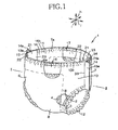
- Fig. 1 is a perspective view showing a pull-on diaper 1
- Fig. 2 is a sectional view taken along the line II-II in Fig. 1
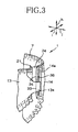
- Fig. 3 is a partial view showing the pull-on diaper 1.
- the diaper 1 is shown as partially cutaway.
- the diaper 1 is composed of a liquid-pervious topsheet 2, a liquid-impervious backsheet 3 and a body fluid absorbent core 4 sandwiched between these two sheets 2, 3.
- the diaper 1 further is configured to define a front waist region 6, a rear waist region 7 and a crotch region 8 destined to cover a front waist region, a rear waist region and a crotch region of the wearer.
- both the topsheet 2 and the backsheet 3 extend outward beyond a peripheral edge of the core 4 and are joined to each other by hot melt adhesives (not shown) in the respective regions thereof extending outward beyond the peripheral edge of the core 4.
- the front waist region 6 defines an upper end 6a and a pair of transversely opposite lateral portions 13 and the rear waist region 7 also defines an upper end 7a and a pair of transversely opposite lateral portions 14.
- each pair of the lateral portions 13, 14 being circumferentially adjacent to each other in a direction of the waist line are connected to each other with interposition of a connector sheet strip 21.
- the front and rear waist regions 6, 7 are annularly connected to each other whereupon the front and rear waist regions 6, 7 form a waist-hole 11 and, at the same time, cooperate with the crotch region 8 to form a pair of leg-holes 12.
- the front and rear waist regions 6, 7 are provided with elastic members 16, 17 extending along front and rear waist lines, respectively, so as to extend along a peripheral edge of the waist-hole 11.
- leg surrounding elastic members 18 extend in a stretched state along a peripheral edge of this leg-hole 12.
- the diaper 1 has a vertical direction, a back-and-forth direction and a transverse direction designated by h, i and j, respectively, and a waist surrounding direction along which the peripheral edge of the waist-hole 11 extends.
- Each of connector sheets 21 adapted to connect the front waist region 6 and the rear waist region 7 cooperating with each other to form the annular waist region is provided along the vicinity of its front side edge 22 and rear side edge 23 as viewed in the waist surrounding direction with joint zones 27, 28 extending in the vertical direction h (See Fig. 2 ) to be permanently joined to respective inner surfaces 13b, 14b of the lateral portions 13, 14 and further provided between these joint zones 27, 28 with an non-joint zone 24 to be left free from both the front waist region 6 and the rear waist region 7.
- the non-joint zone 24 extends between the waist-hole 11 and the leg-hole 12 in the vertical direction h.
- the connector sheet strip 21 has in the non-joint zone 24 a tensile strength and a tear strength which are measured in manners as illustrated in Figs. 5 through 7 .
- the non-joint zone 24 in order to prevent the non-joint zone 24 from being easily broken even if the non-joint zone 24 is strained in the waist surrounding direction as the diaper is put on the wearer's body, the non-joint zone 24 preferably has the tensile strength of at least 8N/width of 25mm in the waist surrounding direction.
- the non-joint zone 24 is adapted to be linearly torn in the vertical direction h from the waist-hole 11 to the leg-hole 12 when the diaper 1 is taken off from the wearer's body.
- the non-joint zone 24 preferably has the tear strength of 0.1 to 12N in the vertical direction h.
- the transversely opposite lateral portions 13 of the front waist region 6 have the ears 13a which extend from the respective joined zones 27 toward the rear waist region 7 as viewed in the waist surrounding direction while the transversely opposite lateral portions 14 of the rear waist region 7 have the ears 14a which extend from the respective joined zones 28 toward the front waist region 6 as viewed in the waist surrounding direction.
- These ears 13a, 14a are laid outside the non-joint zones 24 and folded outwardly of the diaper 1 along respective folds 33, 34so that each pair of the ears 13a, 14a may be opposed to each other.
- One of these ears 13a, 14a opposed to each other may be coated on the inner surface thereof with a pressure-sensitive adhesive 36 to bond these ears 13a, 14a together in a releasable manner.
- the ears 13a are peeled off from the ears 14a as indicated by imaginary lines in Fig. 2 and thereby the connector sheets 21 are exposed outwardly of the diaper 1. Then, the connector sheets 21 are torn apart along the respective non-joint zones 24 in the vertical direction h.
- the elastic members 16, 17 extending along the front and rear waist lines as well as the leg-surrounding elastic members 18 do not extend to the ears 13a, 14a beyond the joint zones 27, 28, it is not apprehended that contraction of these elastic members 16, 17, 18 might form gathers.
- the ears 13a, 14a will be sufficiently flat to facilitate these ears 13a, 14a to be joined together by the adhesive 36 and to eliminate an anxiety that these ears 13a, 14a might be unintentionally peeled off from each other.
- the intended purpose of the adhesive 36 is not to maintain the front and rear waist regions 6, 7 of the diaper 1 joined in the annular state but to bond the opposed ears 13a, 14a temporarily, i.e., in a releasable manner so that the surface of the adhesive 36 may be stained even during actual use of the diaper 1 and the diaper 1 soiled with bodily discharges may be rolled up for disposal thereof in a manner as will be described.
- the non-joint zones 24 of the respective connector sheet strips 21 include none of the elastic members 16, 17 extending along the front and rear waist lines and the leg-surrounding elastic members 18 and therefore there is no anxiety that the presence of these elastic members 16, 17, 18 might make it difficult to tear apart the respective non-joint zones 24 in the vertical direction h.
- the diaper 1 may be alternatively exploited, wherein the connector sheet strips 21 has a color distinguished from that of the ears 13a, 14a so that the non-joint zones 24 of the respective connector sheet strips 21 can be easily identified.
- Fig. 4 is a perspective view showing the diaper 1 which has been taken off from the wearer's body by tearing apart the connector sheet strips 21 and then rolled up from the front waist region 6 toward the rear waist region 7 with the topsheet 2 contaminated with bodily discharges lying on the inside. After has been rolled up in this manner, the ears 14a of the rear waist region 7 may be folded back and fixed to the backsheet 3 by the adhesive 36 to keep this rolled up diaper 1 effectively closed along the lateral portions thereof and thereby to prevent bodily discharges as well as odor from leaking beyond these lateral portions.
- a stock material for the connector sheet strip 21 may be selected from the group, for example, consisting of a nonwoven fabric comprising component fibers made of thermoplastic synthetic resin such as polyethylene, polypropylene or polyester, a film made of such synthetic resin, a lamination sheet comprising the nonwoven fabric and the film as described just above.
- a nonwoven fabric or film may be provided with one or more perforated lines extending in the vertical direction h so as to be easily torn apart.
- the nonwoven fabric or the film may be used so that the specific direction may be conformity with the vertical direction h of the diaper 1 to ensure that the connector sheet strip 21 can be easily torn apart rectilinearly in the vertical direction h.
- a stock material for the topsheet 2 may be selected from the group consisting of a nonwoven fabric made of thermoplastic synthetic resin fibers with a basis weight of 10 to 30g/m 2 and a porous film made of thermoplastic synthetic resin with a thickness of 10 to 30 ⁇ m.
- a stock material for the backsheet 3 may be selected from the group, for example, consisting of a film made of thermoplastic synthetic resin with a thickness of 20 to 50 ⁇ m and a composite sheet comprising such film and nonwoven fabric made of thermoplastic synthetic resin fibers with a basis weight of 20 to 50g/m 2 which are intermittently joined to each other.
- the body fluid absorbent core 4 may be formed from a mixture of fluff pulp and super-absorbent polymer particles wrapped with a sheet material such as a tissue paper or nonwoven fabric having high liquid-permeability and high liquid-diffusivity or fluff pulp wrapped with such sheet material.
- the topsheet 2 and the backsheet 3 are joined together by the known adhesion or heat-sealing technique to form the composite sheet and/or this composite sheet includes the elastic members 16, 17 extending along the front and rear waist lines as well as the leg-surrounding elastic members 18. Therefore, the transversely opposite lateral portions 13, 14 have the tensile strength and the tear strength both higher than those of the connector sheet strips 21 and it is unlikely that these lateral portions 13, 14 might be torn easier than the connector sheet strips 21 when the diaper 1 is taken off from the wearer's body.
- the lateral portions 13 and/or the lateral portions 14 may be formed from one of the topsheet 2 and the backsheet 3 so far as one of these topsheet and backsheet 3 has the tensile strength as well as the tear strength higher than those of the connector sheet strip 21. Furthermore, the lateral portions 13 and/or the lateral portions 14 may be formed from a third sheet provided separately of both the topsheet 2 and the backsheet 3 and having the tensile strength as well as the tear strength higher than the connector sheet strip 21.
- the lateral portions 13, 14 are joined together by the known heat-sealing technique or adhesion along the respective joint zones 27, 28 with a sufficiently high peel strength to eliminate the possibility that the lateral portions 13, 14 might be peeled off from each other as the diaper 1 is put on or taken off from the wearer's body.
- Fig. 5 is a diagram illustrating a method for measurement of tensile strength presented by the sheet material used as the connector sheet strip 21 together with a test piece used for this measurement.
- the test piece is made so as to have a longitudinal direction in conformity with the direction of the diaper's waist line and attached to the tensile tester with an inter-chuck distance of 50mm. This test piece is stretched at a stress rate of 200mm/min to determine a value of the ultimate load until a moment of breakage as the tensile strength.
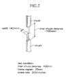
- Figs. 6 and 7 are diagrams respectively illustrating a test piece used for measurement of tear strength of the sheet material used as the connector sheet strip 21 and a method for this measurement.
- the test piece is made so that a longitudinal direction of the test piece itself as well as a slit thereof may be in conformity with the vertical direction h of the diaper 1.
- the test piece is attached to the tensile tester with clamp margins of approximately 25mm, respectively, so that an inter-chuck distance of 100mm may be left free.
- the test piece is stretched at a stress rate of 200mm/min and a value of the maximum load resulting in breakage is determined as the tear strength.
- the connector sheet strips 21 are provided in the vicinity of the transversely opposite lateral portions such that each of the connector sheet strips 21 is substantially bisected and the front half is provided on the front waist region 6 and the rear half is provided on the rear waist region 7.
- positions at which the connector sheet strips 21 are provided are not specified.
- the present invention makes it possible to produce the pull-on disposable wearing article adapted to be taken off from the wearer's body as the transversely opposite lateral portions of the waist region are easily torn apart and, after taken off, to be rolled up for disposal so as to prevent leak of bodily discharge and odor.
Description
- The present invention relates to a disposable pull-on wearing article such as a disposable pull-on diaper or training pants.
- Conventionally, disposable pull-on diapers are well known in the form of a disposable pull-on wearing article. In one example of well known pull-on diapers, a front waist region and a rear waist region are joined together along transversely opposite side edges thereof and these side edges may be torn apart to take the diaper off from the wearer's body. For example, Japanese Unexamined Patent Application Publication No.
1992-371147 PATENT DOCUMENT 1") discloses a disposable pant which can be used as the disposable pull-on diaper. In the case of the pant disclosed therein, a front waist region and a rear waist region are joined together along transversely opposite side edges thereof by use of a heat-sealing means. These side edges joined together in this manner have an appropriate strength such that the pant can be easily torn apart along these side edges to take the pant off from the wearer's body. In the pant, the front waist and rear waist regions are respectively provided with a plurality of thread-like elastic members extending in a transverse direction of these waist regions and attached in a stretched state thereto while the crotch region is provided with a plurality of thread-like elastic members attached in a stretched state thereto so as extend along the peripheral edges of the respective leg-holes. - There has already been proposed also a pull-on wearing article including panels which are elastically stretchable in the direction of the waist line and interposed between a front waist and rear waist regions. For example, National Publication of Translated Version No. 1996-507699 (referred to as "PATENT DOCUMENT 2") discloses a pull-on disposable diaper comprising an absorbent "chassis" and a pair of elastically stretchable "panels". This diaper further comprises a waist-hole and a pair of leg-holes. The "panels" which are elastically stretchable in the direction of the waist line are respectively provided in the vicinity of transversely opposite lateral regions of the wearer and attached to the "chassis" along predetermined joint lines. With this diaper put on the wearer's body, the "chassis" covers the front and rear waist regions as well as the crotch region of the wearer while the "panels" are elastically stretchable and contractible to make the diaper fit the lateral regions of the wearer's waist. When the diaper put on the wearer's body has been soiled with bodily discharges, the "panels" may be torn off from the "chassis" along the joint lines to take the diaper off from the wearer's body without the anxiety that the wearer' s body might be soiled with bodily discharges. This diaper is further provided in the transversely middle zone on the rear waist region's outer surface with an adhesive tape tab used to secure the used diaper in a rolled up state for disposal.
- Japanese Patent Publication No.
3421030 PATENT DOCUMENT 3") discloses a pull-on undergarment. This undergarment comprises a front waist region, a rear waist region and a crotch region wherein the front and rear waist regions are connected together by nonwoven fabric strips adapted to be torn apart with the bare hands. Each of these nonwoven fabric strips extends in a longitudinal direction from one of leg-holes to a waist-hole and may be torn apart in the longitudinal direction to take the undergarment off from the wearer's body. - PATENT DOCUMENT 1: Japanese Unexamined Patent Application Publication No.
1992-371147 - PATENT DOCUMENT 2: National Publication of Translated Version No. 1996-507699
- PATENT DOCUMENT 3: Japanese Patent Publication No.
3421030 - In the case of the pant disclosed in
PATENT DOCUMENT 1, each side edge of the front and rear waist regions comprises an inner sheet formed from a nonwoven fabric and an outer sheet formed from a lamination of a plastic film and a nonwoven fabric or the like. Assumed that the side edges of the front waist region each comprising a plurality of the sheet material layers are placed upon and joined to the side edges of the rear waist region by a heat-sealing means, each of the side edges of the pant would comprise four to six sheet material layers heat sealed together. An effort to tear these side edges joined together apart one from another to take the pant off from the wearer's body may sometimes peel the nonwoven fabric and the plastic film off from each other just along the joined zones and properly disconnect the front and rear waist regions from each other. However, this will be rarely achieved and, in many cases, the front and rear waist regions of the pant will be disconnected from each other with the nonwoven fabric and the plastic film torn not along the joined zones but around the joined zones. In other words, a caregiver for the wearer intending to take the pant off from the wearer's body must tear apart at least two or three layers of the sheet material at once with a considerable force. In addition to this inconvenience, it may be difficult for the caregiver to achieve this operation quickly since it will be rare that these layers of the sheet material are rectilinearly torn apart. Assumed that the waist surrounding elastic members and the leg-surrounding elastic members are attached in a stretched state to the pant, respectively, these elastic members may be peeled off from the nonwoven fabric and the plastic film and thereupon intensely contract just as the side edges of the pant are torn apart. These elastic members peeled off in this manner may painfully hit against the fingertips of the caregiver. Furthermore, the pant taken off from the wearer's body will be formed with a plurality of complicated gathers due to contraction of the waist-surrounding elastic members and the leg-surrounding elastic members and these complicated gathers will make it difficult to roll up or to fold the used pant for disposal in a manner such that the inner surface contaminated with bodily discharges might not be exposed. - The diaper disposed in PATENT
DOCUMENT 2 is said to ensure that the stretchable "panels" can be removed from the "chassis" along the joint lines of the "panels" and the "chassis". However, on the assumption that these joint lines are formed by a heat-sealing means the stretchable "panels" with the "chassis", operation of removing the "panels" from the "chassis" will really comprises, just like in the case of the pant disclosed in PATENTDOCUMENT 1, operation of tearing the "panels" and/or the "chassis" along the joint lines. Such operation will require a considerable force and it may be difficult for the caregiver to achieve this operation quickly. Assumed that the stretchable "panels" include thread-like elastic members attached in a stretched state thereto, these elastic members intensely contract just as these "panels" are removed, and may painfully hit against the fingertips of the caregiver. Furthermore, upon removal of the "panels" from the "chassis", the transversely opposite lateral portions of the diaper are opened and, even after the diaper has been rolled up in the longitudinal direction and fixed in this rolled up state, the lateral portions remain opened. As a result, bodily discharges and odor may leak through these lateral portions remaining opened. - The diaper disclosed in
PATENT DOCUMENT 3 has no means for maintaining the used diaper in a rolled up state and it is likely that the soiled regions of the used diaper may be exposed and cause emission of odor. - In view of the problems as have been described above observed when the conventional wearing articles are taken off from the wearer's body, it is an object of the present invention to improve the known disposable pull-on wearing article.
- According to the present invention, there is provided a disposable pull-on wearing article having a vertical direction, a back-and-forth direction and a transverse direction being orthogonal one to another, the article comprising: an annular waist region having a front section and a rear section; a crotch region extending between the front and rear sections of the annular waist region; a waist hole; a pair of leg-holes; a first elastic member extending along a peripheral edge of the waist holes; second elastic members extending along peripheral edges of the pair of leg-holes; and tear-apart lines being capable of separating the front and rear sections of the annular waist region and extending from the waist hole to each of the leg-holes in the vertical direction.
- The article is characterized in that:
- a pair of connector sheets each has an outer surface, an inner surface opposite to the outer surface, joint zones extending on transversely opposite lateral zones of the outer surface in the vertical direction and a non-j oint zone extending between the joint zones and being capable of tearing apart in the vertical direction for defining the tear-apart lines. The connector sheets each extends from the waist hole to each of the leg-holes in the vertical direction and the joint zones are permanently joined to inner surfaces of the transversely opposite lateral zones of the front and rear sections of the waist region which are separated from each other in the transverse direction. The front and rear sections of the waist region are provided contiguously to the lateral zones thereof with ears each lying outside the non-joint zone of each of the connector sheets and extending from the waist hole to each of the leg-holes, and each pair of the ears facing each other have respective inner surfaces releasably joined to each other with an adhesive. At least the non-joint zone of each of the connector sheets including none of the first and second elastic members.
- According to a preferred embodiment of the invention, at least one of the front and rear sections is provided with an elastic member extending along a waist line and a segment of the elastic member extending between the joint zones is attached in a stretched state thereto but remaining segments extending toward the ears beyond the joint zones are attached thereto not in a stretched state.
- According to the embodiment of the invention, the waist region is provided in a vicinity of the transversely opposite lateral portions with a pair of sheet strips adapted to connect the transversely opposite lateral portions of the front section to the transversely opposite lateral portions of the rear section and to facilitate the formation of the tear-apart lines. This unique arrangement facilitates the used diaper soiled with bodily discharges to be quickly taken off from the wearer's body merely by tearing apart these sheet strips. For disposal of the diaper taken off in this manner may be rolled up from the front section toward the rear section or vice versa and a pressure-sensitive adhesive coated on the ears of the front or rear section may be utilized to fasten the diaper rolled up in this manner to prevent bodily discharges and odor thereof from leaking beyond the lateral portions of this rolled up diaper. In addition, the sheet strips include none of elastic members extending in the direction of the waist line and therefore operation of tearing these sheet strips in the vertical direction is not affected by the presence of these elastic members.
- According to another embodiment of the invention, while the article includes the elastic member extending in the direction of the waist line and attached in a stretched state thereto, this elastic member is not in stretched state in each pair of the ears releasably joined to each other. Therefore, it is unlikely that these ears might be easily peeled off from each other due to stretching and contraction of the elastic member.
-
- [
FIG. 1] Fig. 1 is a partially cutaway perspective view showing a pull-on diaper. - [
FIG. 2] Fig. 2 is a sectional view taken along the line II-II inFig. 1 . - [
FIG. 3] Fig. 3 is a partially enlarged perspective view partially showing the pull-on diaper. - [
FIG. 4] Fig. 4 is a perspective view showing the diaper as rolled up. - [
FIG. 5] Fig. 5 is a diagram schematically illustrating a method for measurement of tensile strength. - [
FIG. 6] Fig. 6 is a diagram schematically illustrating a test piece used for measurement of tear strength. - [
FIG. 7] Fig. 7 is a diagram schematically illustrating a method for measurement of tear strength. -
- 1
- pants-type wearing article (diaper)
- 6
- front section (front waist region)
- 7
- rear section (rear waist region)
- 8
- crotch region
- 11
- waist-hole
- 12
- leg-holes
- 13
- transversely opposite lateral portions
- 13a
- ears
- 13b
- inner surfaces
- 14
- transversely opposite lateral portions
- 14a
- ears
- 14b
- inner surfaces
- 16
- elastic member extending along front waist line
- 17
- elastic member extending along rear waist line
- 18
- leg-surrounding elastic members
- 21
- sheet strips
- 24
- non-joint zones
- 27
- joint zones
- 28
- joint zones
- 36
- pressure-sensitive adhesive
- Details of a disposable pull-on wearing article will be more fully understood from the description of a disposable pull-on diaper as an embodiment of the invention given hereunder with reference to the accompanying drawings.
-
Fig. 1 is a perspective view showing a pull-ondiaper 1,Fig. 2 is a sectional view taken along the line II-II inFig. 1 , andFig. 3 is a partial view showing the pull-ondiaper 1. InFigs. 1 and3 , thediaper 1 is shown as partially cutaway. Thediaper 1 is composed of a liquid-pervious topsheet 2, a liquid-impervious backsheet 3 and a body fluidabsorbent core 4 sandwiched between these twosheets diaper 1 further is configured to define afront waist region 6, arear waist region 7 and acrotch region 8 destined to cover a front waist region, a rear waist region and a crotch region of the wearer. In therespective regions topsheet 2 and thebacksheet 3 extend outward beyond a peripheral edge of thecore 4 and are joined to each other by hot melt adhesives (not shown) in the respective regions thereof extending outward beyond the peripheral edge of thecore 4. Thefront waist region 6 defines anupper end 6a and a pair of transversely oppositelateral portions 13 and therear waist region 7 also defines anupper end 7a and a pair of transversely oppositelateral portions 14. Along both lateral portions of thediaper 1, each pair of thelateral portions connector sheet strip 21. Consequentially, the front andrear waist regions rear waist regions hole 11 and, at the same time, cooperate with thecrotch region 8 to form a pair of leg-holes 12. The respectivelateral portions ears rear waist regions elastic members hole 11. In thecrotch region 8, leg surrounding elastic members 18 extend in a stretched state along a peripheral edge of this leg-hole 12. Theseelastic members topsheet 2 and thebacksheet 3 and joined in a stretched state to at least one of thesesheets diaper 1 has a vertical direction, a back-and-forth direction and a transverse direction designated by h, i and j, respectively, and a waist surrounding direction along which the peripheral edge of the waist-hole 11 extends. - Each of
connector sheets 21 adapted to connect thefront waist region 6 and therear waist region 7 cooperating with each other to form the annular waist region is provided along the vicinity of itsfront side edge 22 andrear side edge 23 as viewed in the waist surrounding direction withjoint zones Fig. 2 ) to be permanently joined to respectiveinner surfaces lateral portions joint zones non-joint zone 24 to be left free from both thefront waist region 6 and therear waist region 7. Thenon-joint zone 24 extends between the waist-hole 11 and the leg-hole 12 in the vertical direction h. Theconnector sheet strip 21 has in the non-joint zone 24 a tensile strength and a tear strength which are measured in manners as illustrated inFigs. 5 through 7 . Specifically, in order to prevent thenon-joint zone 24 from being easily broken even if thenon-joint zone 24 is strained in the waist surrounding direction as the diaper is put on the wearer's body, thenon-joint zone 24 preferably has the tensile strength of at least 8N/width of 25mm in the waist surrounding direction. Thenon-joint zone 24 is adapted to be linearly torn in the vertical direction h from the waist-hole 11 to the leg-hole 12 when thediaper 1 is taken off from the wearer's body. To make this possible, thenon-joint zone 24 preferably has the tear strength of 0.1 to 12N in the vertical direction h. The transversely oppositelateral portions 13 of thefront waist region 6 have theears 13a which extend from the respective joinedzones 27 toward therear waist region 7 as viewed in the waist surrounding direction while the transversely oppositelateral portions 14 of therear waist region 7 have theears 14a which extend from the respective joinedzones 28 toward thefront waist region 6 as viewed in the waist surrounding direction. Theseears non-joint zones 24 and folded outwardly of thediaper 1 alongrespective folds 33, 34so that each pair of theears ears sensitive adhesive 36 to bond theseears diaper 1 off from the wearer's body, theears 13a are peeled off from theears 14a as indicated by imaginary lines inFig. 2 and thereby theconnector sheets 21 are exposed outwardly of thediaper 1. Then, theconnector sheets 21 are torn apart along the respectivenon-joint zones 24 in the vertical direction h. Assumed that theelastic members ears joint zones elastic members ears ears ears elastic members ears joint zones elastic members rear waist regions diaper 1 joined in the annular state but to bond theopposed ears diaper 1 and thediaper 1 soiled with bodily discharges may be rolled up for disposal thereof in a manner as will be described. - In the
diaper 1, thenon-joint zones 24 of the respective connector sheet strips 21 include none of theelastic members elastic members non-joint zones 24 in the vertical direction h. In addition, there is no anxiety that the elastic members might acutely hit against the fingertips of a caregiver for the wearer tearing apart thediaper 1 upon intense contraction of the elastic members having been in a stretched state contract as the conventional pull-on diaper has been the case. Thediaper 1 may be alternatively exploited, wherein the connector sheet strips 21 has a color distinguished from that of theears non-joint zones 24 of the respective connector sheet strips 21 can be easily identified. -
Fig. 4 is a perspective view showing thediaper 1 which has been taken off from the wearer's body by tearing apart the connector sheet strips 21 and then rolled up from thefront waist region 6 toward therear waist region 7 with thetopsheet 2 contaminated with bodily discharges lying on the inside. After has been rolled up in this manner, theears 14a of therear waist region 7 may be folded back and fixed to thebacksheet 3 by the adhesive 36 to keep this rolled updiaper 1 effectively closed along the lateral portions thereof and thereby to prevent bodily discharges as well as odor from leaking beyond these lateral portions. Assumed that thediaper 1 soiled in thecrotch region 8 with bodily discharges is rolled up from thefront waist region 6 toward therear waist region 7 or vice versa so as to wrap around the soiledcrotch region 8 with the unsoiled front andrear waist regions upper ends Fig. 1 ) but it is likely that bodily discharges and odor might leak beyond the transversely opposite lateral portions of thediaper 1. Such likelihood can be effectively prevented by closing the lateral portions by using theears Fig. 4 . - To exploit the present invention, a stock material for the
connector sheet strip 21 may be selected from the group, for example, consisting of a nonwoven fabric comprising component fibers made of thermoplastic synthetic resin such as polyethylene, polypropylene or polyester, a film made of such synthetic resin, a lamination sheet comprising the nonwoven fabric and the film as described just above. Such nonwoven fabric or film may be provided with one or more perforated lines extending in the vertical direction h so as to be easily torn apart. As far as the nonwoven fabric composed of fibers prominently oriented in a specific direction or the film in which the macromolecular strands prominently oriented in a specific direction, the nonwoven fabric or the film may be used so that the specific direction may be conformity with the vertical direction h of thediaper 1 to ensure that theconnector sheet strip 21 can be easily torn apart rectilinearly in the vertical direction h. - A stock material for the
topsheet 2 may be selected from the group consisting of a nonwoven fabric made of thermoplastic synthetic resin fibers with a basis weight of 10 to 30g/m2 and a porous film made of thermoplastic synthetic resin with a thickness of 10 to 30 µm. - A stock material for the
backsheet 3 may be selected from the group, for example, consisting of a film made of thermoplastic synthetic resin with a thickness of 20 to 50 µm and a composite sheet comprising such film and nonwoven fabric made of thermoplastic synthetic resin fibers with a basis weight of 20 to 50g/m2 which are intermittently joined to each other. - The body fluid
absorbent core 4 may be formed from a mixture of fluff pulp and super-absorbent polymer particles wrapped with a sheet material such as a tissue paper or nonwoven fabric having high liquid-permeability and high liquid-diffusivity or fluff pulp wrapped with such sheet material. - Along the transversely opposite
lateral portions rear waist regions topsheet 2 and thebacksheet 3 are joined together by the known adhesion or heat-sealing technique to form the composite sheet and/or this composite sheet includes theelastic members lateral portions lateral portions diaper 1 is taken off from the wearer's body. In the case of thediaper 1 according to the invention, thelateral portions 13 and/or thelateral portions 14 may be formed from one of thetopsheet 2 and thebacksheet 3 so far as one of these topsheet andbacksheet 3 has the tensile strength as well as the tear strength higher than those of theconnector sheet strip 21. Furthermore, thelateral portions 13 and/or thelateral portions 14 may be formed from a third sheet provided separately of both thetopsheet 2 and thebacksheet 3 and having the tensile strength as well as the tear strength higher than theconnector sheet strip 21. Thelateral portions joint zones lateral portions diaper 1 is put on or taken off from the wearer's body. -
Fig. 5 is a diagram illustrating a method for measurement of tensile strength presented by the sheet material used as theconnector sheet strip 21 together with a test piece used for this measurement. The test piece is made so as to have a longitudinal direction in conformity with the direction of the diaper's waist line and attached to the tensile tester with an inter-chuck distance of 50mm. This test piece is stretched at a stress rate of 200mm/min to determine a value of the ultimate load until a moment of breakage as the tensile strength. -
Figs. 6 and7 are diagrams respectively illustrating a test piece used for measurement of tear strength of the sheet material used as theconnector sheet strip 21 and a method for this measurement. The test piece is made so that a longitudinal direction of the test piece itself as well as a slit thereof may be in conformity with the vertical direction h of thediaper 1. The test piece is attached to the tensile tester with clamp margins of approximately 25mm, respectively, so that an inter-chuck distance of 100mm may be left free. The test piece is stretched at a stress rate of 200mm/min and a value of the maximum load resulting in breakage is determined as the tear strength. - While the present invention has been described hereinabove with respect to the disposable pull-on diaper, this invention may be applicable to the other disposable wearing article such as training pants, pants for incontinent patient or sanitary shorts. In the illustrated embodiment, the connector sheet strips 21 are provided in the vicinity of the transversely opposite lateral portions such that each of the connector sheet strips 21 is substantially bisected and the front half is provided on the
front waist region 6 and the rear half is provided on therear waist region 7. However, positions at which the connector sheet strips 21 are provided are not specified. Specifically, it is also possible without departing from the spirit and the scope of the invention to provide the connector sheet strips 21 optionally at the positions put aside from the lateral portions of the waist region toward the wearer' abdomen or back. - The present invention makes it possible to produce the pull-on disposable wearing article adapted to be taken off from the wearer's body as the transversely opposite lateral portions of the waist region are easily torn apart and, after taken off, to be rolled up for disposal so as to prevent leak of bodily discharge and odor.
Claims (2)
- A disposable pull-on wearing article (1) having a vertical direction (h) a back-and-forth direction (i) and a transverse direction (j) being orthogonal one to another, said article comprising:an annular waist region having a front section and a rear section (7a);a crotch region (8) extending between said front and rear sections of said annular waist region;a waist hole (11);a pair of leg-holes (12),a first elastic member (16,17) extending along a peripheral edge of said waist hole;second elastic members (18) extending along peripheral edges of said pair of leg-holes; andtear-apart lines being capable of separating said front and rear sections (6, 7) of said annular waist region and extending from said waist hole (11) to each of said leg-holes (12) in said vertical direction (h); said article being characterized in that:a pair of connector sheets (21) each has an outer surface, an inner surface opposite to said outer surface, joint zones (27, 28) extending on transversely opposite lateral zones of said outer surface in said vertical direction (h) and a non-joint zone (24) extending between said joint zones (27, 28) and is capable of tearing apart in said vertical direction for defining said tear-apart lines;said connector sheets (21) each extends from said waist hole (11) to each of said leg-holes in said vertical direction (h) and said joint zones are permanently joined to inner surfaces of said transversely opposite lateral zones (13,14) of said front and rear sections (6,7) of said waist region which are separated from each other in said transverse direction;said front and rear sections (6,7) of said waist region are provided contiguously to said lateral zones thereof with ears (13a,14a) each lying outside said non-joint zone (24) of each of said connector sheets (21) and extending from said waist hole to each of said leg-holes, and each pair of said ears (13a,14a) facing each other have respective inner surfaces releasably joined to each other with an adhesive (36) ; andat least said non-joint zone (24) of each of said connector sheets (21) includes none of said first and second elastic members (16,17,18).
- The wearing article as defined by Claim 1, wherein at least one of said front and rear sections (6, 7) is provided with an elastic member (16,17) extending along a waist line and a segment of the elastic member (16,17) extending between the joint zones (27,28) is attached in a stretched state thereto but remaining segments extending toward said ears (13a,14a) beyond said joint zones (27,28) are attached thereto not in a stretched state.
Applications Claiming Priority (2)
| Application Number | Priority Date | Filing Date | Title |
|---|---|---|---|
| JP2005173996A JP4678721B2 (en) | 2005-06-14 | 2005-06-14 | Disposable pants-type wearing articles |
| PCT/JP2006/311798 WO2006134894A1 (en) | 2005-06-14 | 2006-06-13 | Disposable pants type wearing article |
Publications (3)
| Publication Number | Publication Date |
|---|---|
| EP1891920A1 EP1891920A1 (en) | 2008-02-27 |
| EP1891920A4 EP1891920A4 (en) | 2011-08-31 |
| EP1891920B1 true EP1891920B1 (en) | 2012-09-26 |
Family
ID=37525028
Family Applications (1)
| Application Number | Title | Priority Date | Filing Date |
|---|---|---|---|
| EP06757283A Not-in-force EP1891920B1 (en) | 2005-06-14 | 2006-06-13 | Disposable pants type wearing article |
Country Status (7)
| Country | Link |
|---|---|
| US (1) | US7717896B2 (en) |
| EP (1) | EP1891920B1 (en) |
| JP (1) | JP4678721B2 (en) |
| KR (1) | KR101066671B1 (en) |
| CN (1) | CN101170980B (en) |
| TW (1) | TWI295569B (en) |
| WO (1) | WO2006134894A1 (en) |
Families Citing this family (13)
| Publication number | Priority date | Publication date | Assignee | Title |
|---|---|---|---|---|
| JP4705405B2 (en) * | 2005-04-27 | 2011-06-22 | ユニ・チャーム株式会社 | Pants-type disposable wearing articles |
| JP5421547B2 (en) * | 2008-05-15 | 2014-02-19 | ユニ・チャーム株式会社 | Pants-shaped wearing articles |
| US8168034B2 (en) * | 2008-09-30 | 2012-05-01 | Uni-Charm Corporation | Manufacturing method of absorbent article |
| DE102009015041A1 (en) * | 2009-03-26 | 2010-09-30 | Paul Hartmann Ag | Absorbent disposable incontinence diaper with side sections |
| JP5619393B2 (en) * | 2009-08-21 | 2014-11-05 | 株式会社リブドゥコーポレーション | Absorption pad |
| US8632518B2 (en) * | 2009-11-24 | 2014-01-21 | The Procter & Gamble Plaza | Absorbent articles and method for manufacturing same |
| US8777913B2 (en) * | 2009-11-24 | 2014-07-15 | The Procter & Gamble Company | Absorbent articles and method for manufacturing the same |
| WO2011091110A2 (en) * | 2010-01-20 | 2011-07-28 | The Procter & Gamble Company | Refastenable absorbent article |
| JP5612129B2 (en) | 2010-01-20 | 2014-10-22 | ザ プロクター アンド ギャンブルカンパニー | Refastenable absorbent article |
| US8601665B2 (en) * | 2010-01-20 | 2013-12-10 | The Procter & Gamble Company | Refastenable absorbent article |
| JP2013517105A (en) * | 2010-01-20 | 2013-05-16 | ザ プロクター アンド ギャンブル カンパニー | Refastenable absorbent article |
| US20110174432A1 (en) * | 2010-01-20 | 2011-07-21 | Gary Dean Lavon | Refastenable Absorbent Article |
| US20220287893A1 (en) * | 2021-03-11 | 2022-09-15 | The Procter & Gamble Company | Absorbent article with closure mechanism |
Family Cites Families (12)
| Publication number | Priority date | Publication date | Assignee | Title |
|---|---|---|---|---|
| JPH01141711U (en) * | 1988-03-14 | 1989-09-28 | ||
| US5074854A (en) * | 1990-08-24 | 1991-12-24 | The Procter & Gamble Co. | Disposable undergarment having a break-away panel |
| JP2988541B2 (en) | 1991-06-19 | 1999-12-13 | ユニ・チャーム株式会社 | Disposable pants-type diapers |
| ES2106886T3 (en) | 1992-10-27 | 1997-11-16 | Procter & Gamble Far East Inc | DISPOSABLE DIAPER WITH A COMPLETELY ELASTIFIED WAIST OPENING. |
| ES2156294T3 (en) * | 1995-10-10 | 2001-06-16 | Procter & Gamble | SEAM WITHOUT EYELASH FOR USE IN DISPOSABLE ITEMS AND MANUFACTURING METHOD. |
| US5662638A (en) * | 1995-10-10 | 1997-09-02 | The Procter & Gamble Company | Flangeless seam for use in disposable articles |
| US6352528B1 (en) * | 1999-11-22 | 2002-03-05 | Kimberly-Clark Worldwide, Inc. | Absorbent articles including hidden graphics |
| AR021905A1 (en) * | 1998-12-18 | 2002-09-04 | Kimberly Clark Co | AN ABSORBENT ARTICLE WITH NON-IRRITANT RESUJETABLE STITCHES |
| JP4540215B2 (en) * | 2000-11-20 | 2010-09-08 | 株式会社リブドゥコーポレーション | Disposable pants and manufacturing method thereof |
| JP4745628B2 (en) * | 2003-08-19 | 2011-08-10 | ユニ・チャーム株式会社 | Disposable wearing items |
| JP4727265B2 (en) * | 2005-03-17 | 2011-07-20 | ユニ・チャーム株式会社 | Disposable pants-type wearing articles |
| JP4705405B2 (en) * | 2005-04-27 | 2011-06-22 | ユニ・チャーム株式会社 | Pants-type disposable wearing articles |
-
2005
- 2005-06-14 JP JP2005173996A patent/JP4678721B2/en not_active Expired - Fee Related
-
2006
- 2006-06-02 TW TW095119688A patent/TWI295569B/en not_active IP Right Cessation
- 2006-06-13 WO PCT/JP2006/311798 patent/WO2006134894A1/en active Application Filing
- 2006-06-13 CN CN2006800149486A patent/CN101170980B/en not_active Expired - Fee Related
- 2006-06-13 KR KR1020077029311A patent/KR101066671B1/en not_active IP Right Cessation
- 2006-06-13 EP EP06757283A patent/EP1891920B1/en not_active Not-in-force
- 2006-06-13 US US11/423,923 patent/US7717896B2/en not_active Expired - Fee Related
Also Published As
| Publication number | Publication date |
|---|---|
| CN101170980A (en) | 2008-04-30 |
| EP1891920A4 (en) | 2011-08-31 |
| KR20080036006A (en) | 2008-04-24 |
| TW200718405A (en) | 2007-05-16 |
| JP2006346004A (en) | 2006-12-28 |
| US7717896B2 (en) | 2010-05-18 |
| KR101066671B1 (en) | 2011-09-21 |
| JP4678721B2 (en) | 2011-04-27 |
| WO2006134894A1 (en) | 2006-12-21 |
| US20060282057A1 (en) | 2006-12-14 |
| EP1891920A1 (en) | 2008-02-27 |
| CN101170980B (en) | 2011-02-16 |
| TWI295569B (en) | 2008-04-11 |
Similar Documents
| Publication | Publication Date | Title |
|---|---|---|
| EP1891920B1 (en) | Disposable pants type wearing article | |
| EP1872759B1 (en) | Disposable pants-type wearing article | |
| US8992496B2 (en) | Convertible absorbent article | |
| JP3699331B2 (en) | Pants-type disposable wearing articles | |
| US7765614B2 (en) | Disposable wearing article | |
| EP1712213B1 (en) | Disposable wearing article | |
| US20060206092A1 (en) | Disposable wearing article and process for making the same | |
| EP2286774B1 (en) | Wearing article and method of folding the same | |
| EP1875887B1 (en) | Pull-on disposable wearing article | |
| EP1839635B1 (en) | Disposable wearing article | |
| CA2495665C (en) | Disposable wearing article | |
| EP1839636B1 (en) | Disposable wearing article | |
| CN110960359B (en) | Wearable article with disposal packaging component | |
| CN112512477B (en) | Wearable article with improved disposal tape | |
| CN112469376B (en) | Wearable article with integrated disposal tape |
Legal Events
| Date | Code | Title | Description |
|---|---|---|---|
| PUAI | Public reference made under article 153(3) epc to a published international application that has entered the european phase |
Free format text: ORIGINAL CODE: 0009012 |
|
| 17P | Request for examination filed |
Effective date: 20070928 |
|
| AK | Designated contracting states |
Kind code of ref document: A1 Designated state(s): AT BE BG CH CY CZ DE DK EE ES FI FR GB GR HU IE IS IT LI LT LU LV MC NL PL PT RO SE SI SK TR |
|
| DAX | Request for extension of the european patent (deleted) | ||
| DAX | Request for extension of the european patent (deleted) | ||
| A4 | Supplementary search report drawn up and despatched |
Effective date: 20110801 |
|
| RIC1 | Information provided on ipc code assigned before grant |
Ipc: A61F 13/49 20060101ALI20110726BHEP Ipc: A61F 13/15 20060101ALI20110726BHEP Ipc: A61F 13/496 20060101AFI20110726BHEP Ipc: A61F 13/551 20060101ALI20110726BHEP |
|
| GRAP | Despatch of communication of intention to grant a patent |
Free format text: ORIGINAL CODE: EPIDOSNIGR1 |
|
| GRAS | Grant fee paid |
Free format text: ORIGINAL CODE: EPIDOSNIGR3 |
|
| GRAA | (expected) grant |
Free format text: ORIGINAL CODE: 0009210 |
|
| AK | Designated contracting states |
Kind code of ref document: B1 Designated state(s): AT BE BG CH CY CZ DE DK EE ES FI FR GB GR HU IE IS IT LI LT LU LV MC NL PL PT RO SE SI SK TR |
|
| REG | Reference to a national code |
Ref country code: GB Ref legal event code: FG4D |
|
| REG | Reference to a national code |
Ref country code: CH Ref legal event code: EP |
|
| REG | Reference to a national code |
Ref country code: AT Ref legal event code: REF Ref document number: 576672 Country of ref document: AT Kind code of ref document: T Effective date: 20121015 |
|
| REG | Reference to a national code |
Ref country code: IE Ref legal event code: FG4D |
|
| REG | Reference to a national code |
Ref country code: DE Ref legal event code: R096 Ref document number: 602006032165 Country of ref document: DE Effective date: 20121122 |
|
| REG | Reference to a national code |
Ref country code: SE Ref legal event code: TRGR |
|
| PG25 | Lapsed in a contracting state [announced via postgrant information from national office to epo] |
Ref country code: LT Free format text: LAPSE BECAUSE OF FAILURE TO SUBMIT A TRANSLATION OF THE DESCRIPTION OR TO PAY THE FEE WITHIN THE PRESCRIBED TIME-LIMIT Effective date: 20120926 Ref country code: FI Free format text: LAPSE BECAUSE OF FAILURE TO SUBMIT A TRANSLATION OF THE DESCRIPTION OR TO PAY THE FEE WITHIN THE PRESCRIBED TIME-LIMIT Effective date: 20120926 |
|
| REG | Reference to a national code |
Ref country code: AT Ref legal event code: MK05 Ref document number: 576672 Country of ref document: AT Kind code of ref document: T Effective date: 20120926 |
|
| REG | Reference to a national code |
Ref country code: LT Ref legal event code: MG4D Effective date: 20120926 |
|
| REG | Reference to a national code |
Ref country code: NL Ref legal event code: VDEP Effective date: 20120926 |
|
| PG25 | Lapsed in a contracting state [announced via postgrant information from national office to epo] |
Ref country code: GR Free format text: LAPSE BECAUSE OF FAILURE TO SUBMIT A TRANSLATION OF THE DESCRIPTION OR TO PAY THE FEE WITHIN THE PRESCRIBED TIME-LIMIT Effective date: 20121227 Ref country code: SI Free format text: LAPSE BECAUSE OF FAILURE TO SUBMIT A TRANSLATION OF THE DESCRIPTION OR TO PAY THE FEE WITHIN THE PRESCRIBED TIME-LIMIT Effective date: 20120926 Ref country code: LV Free format text: LAPSE BECAUSE OF FAILURE TO SUBMIT A TRANSLATION OF THE DESCRIPTION OR TO PAY THE FEE WITHIN THE PRESCRIBED TIME-LIMIT Effective date: 20120926 |
|
| PG25 | Lapsed in a contracting state [announced via postgrant information from national office to epo] |
Ref country code: NL Free format text: LAPSE BECAUSE OF FAILURE TO SUBMIT A TRANSLATION OF THE DESCRIPTION OR TO PAY THE FEE WITHIN THE PRESCRIBED TIME-LIMIT Effective date: 20120926 Ref country code: ES Free format text: LAPSE BECAUSE OF FAILURE TO SUBMIT A TRANSLATION OF THE DESCRIPTION OR TO PAY THE FEE WITHIN THE PRESCRIBED TIME-LIMIT Effective date: 20130106 Ref country code: IS Free format text: LAPSE BECAUSE OF FAILURE TO SUBMIT A TRANSLATION OF THE DESCRIPTION OR TO PAY THE FEE WITHIN THE PRESCRIBED TIME-LIMIT Effective date: 20130126 Ref country code: RO Free format text: LAPSE BECAUSE OF FAILURE TO SUBMIT A TRANSLATION OF THE DESCRIPTION OR TO PAY THE FEE WITHIN THE PRESCRIBED TIME-LIMIT Effective date: 20120926 Ref country code: CZ Free format text: LAPSE BECAUSE OF FAILURE TO SUBMIT A TRANSLATION OF THE DESCRIPTION OR TO PAY THE FEE WITHIN THE PRESCRIBED TIME-LIMIT Effective date: 20120926 Ref country code: EE Free format text: LAPSE BECAUSE OF FAILURE TO SUBMIT A TRANSLATION OF THE DESCRIPTION OR TO PAY THE FEE WITHIN THE PRESCRIBED TIME-LIMIT Effective date: 20120926 Ref country code: BE Free format text: LAPSE BECAUSE OF FAILURE TO SUBMIT A TRANSLATION OF THE DESCRIPTION OR TO PAY THE FEE WITHIN THE PRESCRIBED TIME-LIMIT Effective date: 20120926 |
|
| PG25 | Lapsed in a contracting state [announced via postgrant information from national office to epo] |
Ref country code: SK Free format text: LAPSE BECAUSE OF FAILURE TO SUBMIT A TRANSLATION OF THE DESCRIPTION OR TO PAY THE FEE WITHIN THE PRESCRIBED TIME-LIMIT Effective date: 20120926 Ref country code: CY Free format text: LAPSE BECAUSE OF FAILURE TO SUBMIT A TRANSLATION OF THE DESCRIPTION OR TO PAY THE FEE WITHIN THE PRESCRIBED TIME-LIMIT Effective date: 20120926 Ref country code: PL Free format text: LAPSE BECAUSE OF FAILURE TO SUBMIT A TRANSLATION OF THE DESCRIPTION OR TO PAY THE FEE WITHIN THE PRESCRIBED TIME-LIMIT Effective date: 20120926 Ref country code: PT Free format text: LAPSE BECAUSE OF FAILURE TO SUBMIT A TRANSLATION OF THE DESCRIPTION OR TO PAY THE FEE WITHIN THE PRESCRIBED TIME-LIMIT Effective date: 20130128 |
|
| PG25 | Lapsed in a contracting state [announced via postgrant information from national office to epo] |
Ref country code: AT Free format text: LAPSE BECAUSE OF FAILURE TO SUBMIT A TRANSLATION OF THE DESCRIPTION OR TO PAY THE FEE WITHIN THE PRESCRIBED TIME-LIMIT Effective date: 20120926 |
|
| PG25 | Lapsed in a contracting state [announced via postgrant information from national office to epo] |
Ref country code: BG Free format text: LAPSE BECAUSE OF FAILURE TO SUBMIT A TRANSLATION OF THE DESCRIPTION OR TO PAY THE FEE WITHIN THE PRESCRIBED TIME-LIMIT Effective date: 20121226 Ref country code: DK Free format text: LAPSE BECAUSE OF FAILURE TO SUBMIT A TRANSLATION OF THE DESCRIPTION OR TO PAY THE FEE WITHIN THE PRESCRIBED TIME-LIMIT Effective date: 20120926 |
|
| PLBE | No opposition filed within time limit |
Free format text: ORIGINAL CODE: 0009261 |
|
| STAA | Information on the status of an ep patent application or granted ep patent |
Free format text: STATUS: NO OPPOSITION FILED WITHIN TIME LIMIT |
|
| PG25 | Lapsed in a contracting state [announced via postgrant information from national office to epo] |
Ref country code: IT Free format text: LAPSE BECAUSE OF FAILURE TO SUBMIT A TRANSLATION OF THE DESCRIPTION OR TO PAY THE FEE WITHIN THE PRESCRIBED TIME-LIMIT Effective date: 20120926 |
|
| 26N | No opposition filed |
Effective date: 20130627 |
|
| REG | Reference to a national code |
Ref country code: DE Ref legal event code: R097 Ref document number: 602006032165 Country of ref document: DE Effective date: 20130627 |
|
| PG25 | Lapsed in a contracting state [announced via postgrant information from national office to epo] |
Ref country code: MC Free format text: LAPSE BECAUSE OF FAILURE TO SUBMIT A TRANSLATION OF THE DESCRIPTION OR TO PAY THE FEE WITHIN THE PRESCRIBED TIME-LIMIT Effective date: 20120926 |
|
| REG | Reference to a national code |
Ref country code: CH Ref legal event code: PL |
|
| REG | Reference to a national code |
Ref country code: IE Ref legal event code: MM4A |
|
| PG25 | Lapsed in a contracting state [announced via postgrant information from national office to epo] |
Ref country code: CH Free format text: LAPSE BECAUSE OF NON-PAYMENT OF DUE FEES Effective date: 20130630 Ref country code: LI Free format text: LAPSE BECAUSE OF NON-PAYMENT OF DUE FEES Effective date: 20130630 Ref country code: IE Free format text: LAPSE BECAUSE OF NON-PAYMENT OF DUE FEES Effective date: 20130613 |
|
| PG25 | Lapsed in a contracting state [announced via postgrant information from national office to epo] |
Ref country code: TR Free format text: LAPSE BECAUSE OF FAILURE TO SUBMIT A TRANSLATION OF THE DESCRIPTION OR TO PAY THE FEE WITHIN THE PRESCRIBED TIME-LIMIT Effective date: 20120926 |
|
| PG25 | Lapsed in a contracting state [announced via postgrant information from national office to epo] |
Ref country code: HU Free format text: LAPSE BECAUSE OF FAILURE TO SUBMIT A TRANSLATION OF THE DESCRIPTION OR TO PAY THE FEE WITHIN THE PRESCRIBED TIME-LIMIT; INVALID AB INITIO Effective date: 20060613 Ref country code: LU Free format text: LAPSE BECAUSE OF NON-PAYMENT OF DUE FEES Effective date: 20130613 |
|
| REG | Reference to a national code |
Ref country code: FR Ref legal event code: PLFP Year of fee payment: 11 |
|
| REG | Reference to a national code |
Ref country code: FR Ref legal event code: PLFP Year of fee payment: 12 |
|
| PGFP | Annual fee paid to national office [announced via postgrant information from national office to epo] |
Ref country code: GB Payment date: 20170607 Year of fee payment: 12 Ref country code: FR Payment date: 20170511 Year of fee payment: 12 |
|
| PGFP | Annual fee paid to national office [announced via postgrant information from national office to epo] |
Ref country code: SE Payment date: 20170613 Year of fee payment: 12 |
|
| PGFP | Annual fee paid to national office [announced via postgrant information from national office to epo] |
Ref country code: DE Payment date: 20180530 Year of fee payment: 13 |
|
| REG | Reference to a national code |
Ref country code: SE Ref legal event code: EUG |
|
| PG25 | Lapsed in a contracting state [announced via postgrant information from national office to epo] |
Ref country code: SE Free format text: LAPSE BECAUSE OF NON-PAYMENT OF DUE FEES Effective date: 20180614 |
|
| GBPC | Gb: european patent ceased through non-payment of renewal fee |
Effective date: 20180613 |
|
| PG25 | Lapsed in a contracting state [announced via postgrant information from national office to epo] |
Ref country code: GB Free format text: LAPSE BECAUSE OF NON-PAYMENT OF DUE FEES Effective date: 20180613 Ref country code: FR Free format text: LAPSE BECAUSE OF NON-PAYMENT OF DUE FEES Effective date: 20180630 |
|
| REG | Reference to a national code |
Ref country code: DE Ref legal event code: R119 Ref document number: 602006032165 Country of ref document: DE |
|
| PG25 | Lapsed in a contracting state [announced via postgrant information from national office to epo] |
Ref country code: DE Free format text: LAPSE BECAUSE OF NON-PAYMENT OF DUE FEES Effective date: 20200101 |