EP1890614B1 - Instrument porte-outil - Google Patents
Instrument porte-outil Download PDFInfo
- Publication number
- EP1890614B1 EP1890614B1 EP05742131A EP05742131A EP1890614B1 EP 1890614 B1 EP1890614 B1 EP 1890614B1 EP 05742131 A EP05742131 A EP 05742131A EP 05742131 A EP05742131 A EP 05742131A EP 1890614 B1 EP1890614 B1 EP 1890614B1
- Authority
- EP
- European Patent Office
- Prior art keywords
- instrument
- tool
- head
- tube
- holder
- Prior art date
- Legal status (The legal status is an assumption and is not a legal conclusion. Google has not performed a legal analysis and makes no representation as to the accuracy of the status listed.)
- Expired - Lifetime
Links
Images

Classifications
-
- A—HUMAN NECESSITIES
- A61—MEDICAL OR VETERINARY SCIENCE; HYGIENE
- A61B—DIAGNOSIS; SURGERY; IDENTIFICATION
- A61B17/00—Surgical instruments, devices or methods
- A61B17/16—Instruments for performing osteoclasis; Drills or chisels for bones; Trepans
- A61B17/1613—Component parts
- A61B17/1622—Drill handpieces
- A61B17/1624—Drive mechanisms therefor
-
- A—HUMAN NECESSITIES
- A61—MEDICAL OR VETERINARY SCIENCE; HYGIENE
- A61B—DIAGNOSIS; SURGERY; IDENTIFICATION
- A61B17/00—Surgical instruments, devices or methods
- A61B17/16—Instruments for performing osteoclasis; Drills or chisels for bones; Trepans
- A61B17/1613—Component parts
- A61B17/1631—Special drive shafts, e.g. flexible shafts
-
- A—HUMAN NECESSITIES
- A61—MEDICAL OR VETERINARY SCIENCE; HYGIENE
- A61B—DIAGNOSIS; SURGERY; IDENTIFICATION
- A61B17/00—Surgical instruments, devices or methods
- A61B17/16—Instruments for performing osteoclasis; Drills or chisels for bones; Trepans
- A61B17/1613—Component parts
- A61B17/1633—Sleeves, i.e. non-rotating parts surrounding the bit shaft, e.g. the sleeve forming a single unit with the bit shaft
-
- A—HUMAN NECESSITIES
- A61—MEDICAL OR VETERINARY SCIENCE; HYGIENE
- A61B—DIAGNOSIS; SURGERY; IDENTIFICATION
- A61B17/00—Surgical instruments, devices or methods
- A61B17/00234—Surgical instruments, devices or methods for minimally invasive surgery
Definitions
- the present invention relates to a tool-holder shaped longitudinal handle, especially for surgical applications, with a drive shaft for a tool, this shaft can be slid along a longitudinal axis in the instrument from the the rear end of the instrument to be connected to the tool holder portion of a rotary tool housed in a tool head mounted at the front end of the instrument.
- tool-carrying instruments such as drills
- Some instruments have heads through which the tools (drilling, milling, tapping, reaming) are oriented at an angle defined relative to the longitudinal axis of the instrument.
- WO99 / 21686 discloses a mandrel support device that is designed to be used primarily by dentists.
- Three cylindrical elements are arranged end to end so that, thanks to the inclination of the faces of said elements, it is possible to adjust all the angular positions from 0 ° to 90 °.
- Two shafts, one motor shaft and one flexible transmission, are necessary because the second shaft, being flexible, can better accommodate the relative movements of the three elements.
- Said shafts are not slid along the longitudinal axis of the device and can not be disassembled so that effective cleaning can be done.
- An object of the present invention is to provide a tool-holder instrument that can be used under various working action rays in a multitude of techniques, including orthopedic-type operating techniques.
- the instrument according to the present invention has the characteristics according to the characteristic part of claim 1.
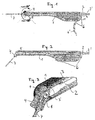
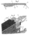
- Fig. 1 of the drawing shows a side view and very schematically a tool-holder according to the invention, comprising a housing 1 in the form of a longitudinal handle and housing inside a drive shaft and a locking tube 3 ( Fig 3 ) which lead from the rear end along a longitudinal axis to a tool head 4 at the front of the instrument.
- the drive shaft 2 and the locking tube 3 can be dismounted from the instrument by pulling them out of the box backwards or be locked in the working position by means of a toggle mechanism 6 (see detail Fig. 6a - 6d ).
- the tool head 4 can be oriented angularly about a fixed axis of ⁇ 180 ° at most from the 0 ° neutral position (directed along the longitudinal axis of the instrument) and is locked in any chosen position by means of said locking tube 3 (see detail Fig. 3 ).
- the Fig. 2 shows the instrument with the drive and lock components 2 resp. 3 locked in the longitudinal direction by the toggle mechanism 6 with the tool head fitted with a tool (drill bit) 7.
- the drive shaft 2 which at the rear end 2 'can be connected to a motor (not shown), is connected in working position at its front end to a tool holder portion 8 for a rotary tool 7 housed in the tool head 4.
- the coupling between the drive shaft 2 and said tool holder portion 8 can be of any construction, for example universal joint type, universal joint, toothed wheel or other.
- the construction of the coupling mechanism allowing an orientation of ⁇ 180 ° will be described in a separate patent and does not form part of the present invention.
- the locking tube 3 in the working position meshes with a toothed portion 9 on the tool head 4 and maintains this head in the chosen position before being blocked.
- the piercing head angular head percussion instrument allows the transmission of a torque when connected to a motor (coupling stryker, hudson, AO or others).
- the main innovation lies in the fact that the tool head 4 is orientable and can cover a radius of action theoretically from + 180 ° to -180 ° passing through 0 °.
- the proximal part of the instrument is compact, and allows minimally invasive techniques.
- the head 4 of the instrument is steerable, thus achieves some bone cavities or difficult access that could only be achieved by several conventional instruments combined.
- the instrument may in some cases substitute for this combination of two instruments and thus facilitate the technique.
- the indexing of the position of the head is by a simple movement of the lowering of the lever 6 '. This releases the knee joint and allows the tube 3 to be retracted. This releases the toothing 9 of the head 4, which can therefore be oriented at the angle chosen by the practitioner and corresponding to the surgical application chosen. . Once the angle chosen, the tube 3 is pushed to lock the toothing 9 of the head 4 and its position.
- the lever 6 ' must be placed in closed position so that it transmits a constant pressure on the toggle which itself, pressing the tube 3 locks the position of the head 4.
- the instrument In this position the instrument can be used in rotation at the chosen angle.
- the instrument can also be completely disassembled for thorough cleaning before sterilization.
- the disassembly mechanism of the instrument is very easy to use and a minimum of movements is necessary in order to perform the disassembly operation. Just lower the lever 6 'which releases the toggle and position the head 4 at 0 °. Then remove the drive shaft 2 and then the tube 3. Once the device is removed, the user will end up with three pieces of instrument (ancillary excluded), ie: the main body 1, the drive shaft 2 and These three separate elements effectively fulfill the requirements and guidelines for the decontamination and cleaning and sterilization of surgical instruments. The instrument is reassembled in the reverse order of the above operations.
- the shape and the lateral grooves on the housing 1 have been studied to allow the fixing of guides to adapt and use the product in the techniques of surgeries by navigation. These grooves also make it possible to fix a sliding side handle in order to gain stability when using the instrument.
Landscapes
- Health & Medical Sciences (AREA)
- Surgery (AREA)
- Life Sciences & Earth Sciences (AREA)
- Biomedical Technology (AREA)
- Medical Informatics (AREA)
- Orthopedic Medicine & Surgery (AREA)
- Oral & Maxillofacial Surgery (AREA)
- Engineering & Computer Science (AREA)
- Dentistry (AREA)
- Heart & Thoracic Surgery (AREA)
- Nuclear Medicine, Radiotherapy & Molecular Imaging (AREA)
- Molecular Biology (AREA)
- Animal Behavior & Ethology (AREA)
- General Health & Medical Sciences (AREA)
- Public Health (AREA)
- Veterinary Medicine (AREA)
- Surgical Instruments (AREA)
- Automatic Tool Replacement In Machine Tools (AREA)
Description
- La présent invention concerne un instrument porte-outil en forme de poignée longitudinale, notamment pour applications chirurgicales, avec un arbre d'entraînement pour un outil, cet arbre pouvant être glissé le long d'un axe longitudinal dans l'instrument à partir de l'extrémité arrière de l'instrument pour être connecte à la partie porte-outil d'un outil rotatif logée dans une tète porte-outil montée à l'extrémité avant de l'instrument.
- Il existe de nombreuses constructions d'instruments porte-outil, comme par exemple des perceurs, notamment utilisés dans la chirurgie orthopédique. Certains instruments présentent des têtes par lesquelles les outils (perçage, fraisage, taraudage, alésage) sont orientes sous un angle défini par rapport à l'axe longitudinal de l'instrument.
-
WO99/21686 - Un but de la présente invention est de prévoir un instrument porte-outil qui soit utilisable sous des rayons d'action de travail variés dans une multitude de techniques, notamment techniques opératoires de type orthopédiques.
- Pour atteindre ce but et résoudre les problèmes relatifs à un instrument porte-outil du type défini ci-dessus, l'instrument présente selon la présente invention les caractéristiques selon la partie caractéristique de la revendication 1.
- Des formes d'exécution particulières et préférées de l'instrument selon l'invention sont définies dans les revendications dépendantes.
- L'invention sera décrite plus en détail ci-après à l'aide de forme d'exécutions illustrées dans le dessin, dans lequel représente:
- Fig. 1
- en vue générale d'un instrument porte-outil selon l'invention, avec les composantes d'entraînement et de verrouillage en position non bloquée;
- Fig. 2
- une vue analogue à celle de la
Fig. 1 avec les composantes en position verrouillée; - Fig. 3
- une vue en perspective d'un détail de l'instrument (tête porte- outil), partiellement en coupe;
- Fig. 4
- l'instrument porte-outil en coupe schématique;
- Fig. 5
- une vue en perspective agrandie d'un autre détail (partie arrière de l'instrument avec mécanisme de blocage à genouillère en position ouverte, et
- Fig. 6a - 6d
- le mécanisme de blocage à genouillère, en partie en coupe, en positon ouverte et fermée respectivement.
- La
Fig. 1 du dessin montre en vue latérale et très schématiquement un instrument porte-outil selon l'invention, comprenant un boitier 1 en forme de poignée longitudinale et logeant à l'intérieur un arbre d'entraînement et un tube de blocage 3 (Fig 3 ) qui mènent de l'extrémité arrière le long d'un axe longitudinal jusqu'a une tête porte-outil 4 à l'avant de l'instrument. - L'arbre d'entraînement 2 et le tube de blocage 3 peuvent être démontés de l'instrument en les tirant hors du boitier vers l'arrière ou être bloquées en position de travail au moyen d'un mécanisme à genouillère 6 (détail voir
Fig. 6a - 6d ). - La tête porte-outil 4 peut être orientée angulairement autour d'un axe fixe 5 de ± 180° au maximum à partir de la positon neutre 0° (dirigé selon l'axe longitudinal de l'instrument) et est bloquée dans toute positon choisie au moyen dudit tube de blocage 3 (voir détail
Fig. 3 ). - La
Fig. 2 montre l'instrument avec les composantes d'entraînement et de blocage 2 resp. 3 bloquées en direction longitudinale par le mécanisme à genouillère 6 avec la tête porte-outil équipée d'un outil (foret) 7. - L'arbre d'entraînement 2, qui à l'extrémité arrière 2' peut être connecté à un moteur (non représenté), est connecté en positon de travail à son extrémité avant à une partie porte-outil 8 pour un outil rotatif 7 logée dans la tête porte-outil 4.
- L'accouplement entre l'arbre d'entraînement 2 et ladite partie porte-outil 8 peut être d'une construction quelconque, par exemple du type joint universel, joint de cardan, roue dentée ou autre. La construction du mécanisme d'accouplement permettant une orientation de ± 180° sera décrite dans un brevet séparé et ne forme pas partie de la présente invention.
- Le tube de blocage 3 en position de travail (blocage de la tête porte-outil 4) s'engrène dans une partie dentée 9 sur
la tête porte-outil 4 et maintient cette tête dans la position choisie avant d'avoir été bloquée. - L'instrument perceur renvoi d'angle à tête orientable permet lors de sa connexion à un moteur (accouplement stryker, hudson, AO ou autres) la transmission d'un couple.
- En connectant différents ancillaires 7 sur le devant de sa tête orientable 4, il autorise, le perçage, le fraisage, le taraudage, l'alésage des différentes parties osseuses lors d'une intervention chirurgicale de type orthopédique. Le système permet lors de la connexion de tournevis à l'instrument, le vissage de diverses vis implantables ou non implantables telles que des vis six pans, torx, cruciformes ou autres.
- La principale innovation réside dans le fait que la tête porte-outil 4 est orientable et peut couvrir un rayon d'action allant théoriquement de + 180° à - 180° en passant par 0°.
- Il permet de couvrir un rayon d'action que les perceurs à renvoi d'angles fixe (ex. 45°) ne peuvent garantir. De ce fait il peut être utilisé dans une multitude de techniques opératoires de type orthopédiques couvrant les chirurgies du genou, de la hanche, de la traumatologie, de la colonne vertébrale, de l'épaule, des extrémités ou de maxillo-facial, où les anatomies osseuses requièrent différentes approches ou accès.
- De par sa conception, la partie proximale de l'instrument est de faible encombrement, et autorise les techniques mini invasives.
- Le fait que la tête 4 de l'instrument soit orientable, permet ainsi d'atteindre certaines cavités osseuses ou accès difficiles qui ne pourraient être atteints que par plusieurs instruments classiques combinés. Pour exemple, nous pouvons citer dans la traumatologie, les réductions de fractures par pose de plaques qui traditionnellement peuvent combiner l'utilisation de divers guides et flexibles lors des perçages et taraudages des passages de vis. L'instrument pourra dans certains cas se substituer à cette combinaison de deux instruments et ainsi faciliter la technique.
- L'indexage de la position de la tête se fait par un mouvement simple de l'abaissement du levier 6'. Celui-ci libère la genouillère et permet le recule du tube 3. Celui-ci libère la denture 9 de la tête 4 qui de ce fait, peut être orientée sous l'angle choisi par le praticien et, correspondant à l'application chirurgicale choisie. Une fois l'angle choisi, le tube 3 est poussé afin de bloquer la denture 9 de la tête 4 et sa position. Le levier 6' doit être mis en positon fermée afin qu'il transmette un pression constante sur la genouillère qui elle-même, en appuyant sur le tube 3 verrouille la positon de la tête 4.
- Dans cette positon l'instrument peut-être utilisé en rotation sous l'angle choisi.
- L'instrument peut également être complètement démonté afin d'effectuer un nettoyage approfondi avant la stérilisation.
- Pour démonter 1 instrument, il s'agit du même mécanisme que celui qui permet d'orienter et de verrouiller la position de l'angle de la tête 4. Le mécanisme de démontage de l'instrument est très simple d'utilisation et un minimum de mouvements est nécessaire afin de réaliser l'opération de démontage. Il suffit d'abaisser le levier 6' qui libère la genouillère et de positionner la tête 4 à 0°. Puis retirer l'arbre de transmission 2 puis le tube 3. Une fois l'appareil démonté, l'utilisateur se retrouvera avec trois morceaux d'instrument (ancillaire exclus), soit: le corps principal 1, l'arbre de transmission 2 et le tube 3. Ces trois éléments séparés remplissent de manière efficace les exigences et les directives relatives à la décontamination et au nettoyage et à la stérilisation des instruments chirurgicaux. Le remontage de l'instrument s'effectue dans l'ordre inverse des opérations ci-dessus.
- La forme et les rainures latérales sur le boitier 1 ont été étudiées pour permettre la fixation de guides afin d'adapter et d'utiliser le produit dans les techniques de chirurgies assistées par navigation. Ces rainures permettent également de fixer une poignée latérale coulissante afin de gagner en stabilité lors de l'utilisation de l'instrument.
Claims (4)
- Instrument porte-outil en forme de poignée longitudinale, notamment pour applications chirurgicales, avec un arbre d'entraînement (2) pour un outil (7), cet arbre (2) pouvant être glissé le long d'un axe longitudinal dans l'instrument à partir de l'extrémité arrière de l'instrument pour être connecté à la partie porte-outil (8) d'un outil rotatif logée dans une tête porte-outil (4) montée à l'extrémité avant de l'instrument, la tête porte-outil (4) logeant ladite partie porte-outil (8) est montée à l'extrémité avant de l'instrument de manière orientable angulairement par rapport à l'axe longitudinal de l'instrument autour d'un axe de pivotement fixe transversal à cet axe, des moyens (3', 9) étant prévus pour bloquer la tête orientable dans toute position angulaire choisie, lesdits moyens comprennent une partie (9) de ladite tête (4) caractérise en ce que lesdits moyens comprennent un tube (3) à introduire dans l'instrument à partir de l'extrémité arrière de l'instrument et entourant ledit arbre d'entraînement (2), le bord avant (3') dudit tube (3) étant destiné à entrer en contact avec ladite partie (9) de ladite tête (4) pour bloquer cette dernière dans une position présélectionnée.
- Instrument selon la revendication 1, comprenant un jeu entre ledit tube (3) et ledit arbre d'entraînement (2) permettant le mouvement relatif libre entre ces deux éléments, dit tube (3) et dit arbre (2) pouvant être montés et démontés individuellement.
- Instrument selon la revendication 2, caractérise par des moyens (6) pour bloquer ledit tube (3) et l'arbre d'entraînement (2) contre un déplacement axial dans leurs
positons de travail, c'est-a-dire en contact de blocage avec la tête (4) respectivement connectée avec ladite partie porte-outil (8) pour entraîner cette dernière. - Instrument selon la revendication 3, caractérise en ce que les moyens de blocage (6) comprennent un mécanisme à genouillère dont les éléments d'arrêt en positon de blocage s'appliquent contre l'arrière dudit tube (3) et le cas échéant contre une partie arrière de l'arbre d'entraînement.
Applications Claiming Priority (1)
| Application Number | Priority Date | Filing Date | Title |
|---|---|---|---|
| PCT/CH2005/000309 WO2006128310A1 (fr) | 2005-06-01 | 2005-06-01 | Instrument porte-outil |
Publications (2)
| Publication Number | Publication Date |
|---|---|
| EP1890614A2 EP1890614A2 (fr) | 2008-02-27 |
| EP1890614B1 true EP1890614B1 (fr) | 2011-09-21 |
Family
ID=35705232
Family Applications (1)
| Application Number | Title | Priority Date | Filing Date |
|---|---|---|---|
| EP05742131A Expired - Lifetime EP1890614B1 (fr) | 2005-06-01 | 2005-06-01 | Instrument porte-outil |
Country Status (4)
| Country | Link |
|---|---|
| US (1) | US20090005798A1 (fr) |
| EP (1) | EP1890614B1 (fr) |
| AT (1) | ATE525027T1 (fr) |
| WO (1) | WO2006128310A1 (fr) |
Families Citing this family (6)
| Publication number | Priority date | Publication date | Assignee | Title |
|---|---|---|---|---|
| US11007063B2 (en) | 2013-03-11 | 2021-05-18 | Catalyst Orthoscience Inc. | Offset reamers |
| US10973646B2 (en) | 2013-03-11 | 2021-04-13 | Catalyst Orthoscience Inc. | Stabilized drill guide |
| US20170319348A1 (en) | 2015-08-10 | 2017-11-09 | Catalyst Orthoscience Inc. | Arthroplasty prostheses with multi-axis fixation |
| US9814471B2 (en) * | 2013-03-11 | 2017-11-14 | Catalyst Orthoscience Inc. | Glenoid arthroplasty and offset reamers |
| US9775716B2 (en) | 2013-03-11 | 2017-10-03 | Catalyst Orthoscience Inc. | Glenoid arthroplasty |
| US20180148271A1 (en) * | 2016-11-28 | 2018-05-31 | Bbhs A/S | Conveyor system comprising an aligner for aligning items |
Family Cites Families (10)
| Publication number | Priority date | Publication date | Assignee | Title |
|---|---|---|---|---|
| US4055185A (en) * | 1976-03-02 | 1977-10-25 | American Sterilizer Company | Rotary drill for surgeons |
| US5251706A (en) * | 1992-12-03 | 1993-10-12 | Jack Evans | Ratchet drive tool with manual and non-manual power actuation |
| AU4569697A (en) | 1997-10-28 | 1999-05-17 | Romolo Bertani | Device for supporting a mandrel with angular transmission |
| US6131261A (en) * | 1998-06-30 | 2000-10-17 | Michlin; Steven Bruce | Arbor press extender device and method |
| US6145413A (en) * | 1998-09-14 | 2000-11-14 | Lin; Ching Chou | Multifunction tool |
| US6095016A (en) * | 1998-09-15 | 2000-08-01 | Lam; Warren | Screw and bolt clamp drive |
| US6715380B2 (en) * | 2001-05-14 | 2004-04-06 | C. & E. Fein Gmbh & Co. Kg | Power-driven screwdriver |
| US6928902B1 (en) * | 2003-03-20 | 2005-08-16 | Luis P. Eyssallenne | Air powered wrench device with pivotable head and method of using |
| US7503921B2 (en) * | 2004-01-13 | 2009-03-17 | Symmetry Medical, Inc. | Variable angle orthopaedic reamer driver |
| US7779931B2 (en) * | 2006-11-10 | 2010-08-24 | Joel Townsan | Electric hand screwdriver with adjustable head |
-
2005
- 2005-06-01 US US11/916,085 patent/US20090005798A1/en not_active Abandoned
- 2005-06-01 AT AT05742131T patent/ATE525027T1/de not_active IP Right Cessation
- 2005-06-01 WO PCT/CH2005/000309 patent/WO2006128310A1/fr not_active Ceased
- 2005-06-01 EP EP05742131A patent/EP1890614B1/fr not_active Expired - Lifetime
Also Published As
| Publication number | Publication date |
|---|---|
| EP1890614A2 (fr) | 2008-02-27 |
| US20090005798A1 (en) | 2009-01-01 |
| WO2006128310A8 (fr) | 2008-01-10 |
| ATE525027T1 (de) | 2011-10-15 |
| WO2006128310A1 (fr) | 2006-12-07 |
Similar Documents
| Publication | Publication Date | Title |
|---|---|---|
| AU2003202555B2 (en) | Surgical instrument for grinding the cotyloid cavity | |
| US7585300B2 (en) | Dissecting high speed burr for spinal surgery | |
| US7976548B2 (en) | Surgical tool holder for facilitated sterilization | |
| US5993454A (en) | Drill attachment for a surgical drill | |
| US8845668B2 (en) | Arthroscopic shaver handpiece with modular attachments | |
| US7100476B1 (en) | Torque wrench for dental implants | |
| KR200487712Y1 (ko) | 수술용 쉐이버 | |
| EP2192862B1 (fr) | Actionneur d'alésoir double | |
| EP1030617B1 (fr) | Dispositif de manipulation d'instruments chirurgicaux | |
| EP3672504A1 (fr) | Système de commande pour dispositif médical de foret rétrograde | |
| EP2394584A1 (fr) | Rétracteur chirurgical | |
| US20060074429A1 (en) | Adjustable angle handle for surgical instruments | |
| FR2861575A1 (fr) | Instrument chirurgical avec fixation en angle | |
| WO2004049956A3 (fr) | Systeme motorise de rongeur de type kerrison | |
| CA3090551A1 (fr) | Systemes chirurgicaux robotises et ensembles d'entrainement d'instrument | |
| EP2016913A1 (fr) | Instrument endoscopique | |
| AU2003282729A1 (en) | Retractor with interchangeable retractor blades | |
| CN113873966A (zh) | 种植体手术用扭力扳手 | |
| CN111035418B (zh) | 可视变向手术动力装置 | |
| US4813413A (en) | Surgical instrument with detachable tool member | |
| EP1890614A2 (fr) | Instrument porte-outil | |
| US20230414264A1 (en) | Articulating surgical tools | |
| JP2003519527A (ja) | 下あご等の顔面骨の骨折手術方法及び手術器具 | |
| CN212382662U (zh) | 便于单手操作的内窥镜刨削系统 | |
| CN209951335U (zh) | 一种用于椎间孔镜手术的镜外可视动力环锯 |
Legal Events
| Date | Code | Title | Description |
|---|---|---|---|
| PUAI | Public reference made under article 153(3) epc to a published international application that has entered the european phase |
Free format text: ORIGINAL CODE: 0009012 |
|
| 17P | Request for examination filed |
Effective date: 20071203 |
|
| AK | Designated contracting states |
Kind code of ref document: A2 Designated state(s): AT BE BG CH CY CZ DE DK EE ES FI FR GB GR HU IE IS IT LI LT LU MC NL PL PT RO SE SI SK TR |
|
| AX | Request for extension of the european patent |
Extension state: AL BA HR LV MK YU |
|
| RAP1 | Party data changed (applicant data changed or rights of an application transferred) |
Owner name: INOMED TECHNOLOGY SA COURTELARY |
|
| DAX | Request for extension of the european patent (deleted) | ||
| 17Q | First examination report despatched |
Effective date: 20090623 |
|
| GRAP | Despatch of communication of intention to grant a patent |
Free format text: ORIGINAL CODE: EPIDOSNIGR1 |
|
| GRAS | Grant fee paid |
Free format text: ORIGINAL CODE: EPIDOSNIGR3 |
|
| GRAA | (expected) grant |
Free format text: ORIGINAL CODE: 0009210 |
|
| AK | Designated contracting states |
Kind code of ref document: B1 Designated state(s): AT BE BG CH CY CZ DE DK EE ES FI FR GB GR HU IE IS IT LI LT LU MC NL PL PT RO SE SI SK TR |
|
| REG | Reference to a national code |
Ref country code: GB Ref legal event code: FG4D Free format text: NOT ENGLISH |
|
| REG | Reference to a national code |
Ref country code: CH Ref legal event code: EP Ref country code: CH Ref legal event code: NV Representative=s name: P&TS SA |
|
| REG | Reference to a national code |
Ref country code: IE Ref legal event code: FG4D Free format text: LANGUAGE OF EP DOCUMENT: FRENCH |
|
| REG | Reference to a national code |
Ref country code: DE Ref legal event code: R096 Ref document number: 602005030132 Country of ref document: DE Effective date: 20111117 |
|
| REG | Reference to a national code |
Ref country code: NL Ref legal event code: VDEP Effective date: 20110921 |
|
| PG25 | Lapsed in a contracting state [announced via postgrant information from national office to epo] |
Ref country code: SE Free format text: LAPSE BECAUSE OF FAILURE TO SUBMIT A TRANSLATION OF THE DESCRIPTION OR TO PAY THE FEE WITHIN THE PRESCRIBED TIME-LIMIT Effective date: 20110921 Ref country code: FI Free format text: LAPSE BECAUSE OF FAILURE TO SUBMIT A TRANSLATION OF THE DESCRIPTION OR TO PAY THE FEE WITHIN THE PRESCRIBED TIME-LIMIT Effective date: 20110921 Ref country code: LT Free format text: LAPSE BECAUSE OF FAILURE TO SUBMIT A TRANSLATION OF THE DESCRIPTION OR TO PAY THE FEE WITHIN THE PRESCRIBED TIME-LIMIT Effective date: 20110921 |
|
| LTIE | Lt: invalidation of european patent or patent extension |
Effective date: 20110921 |
|
| PG25 | Lapsed in a contracting state [announced via postgrant information from national office to epo] |
Ref country code: AT Free format text: LAPSE BECAUSE OF FAILURE TO SUBMIT A TRANSLATION OF THE DESCRIPTION OR TO PAY THE FEE WITHIN THE PRESCRIBED TIME-LIMIT Effective date: 20110921 Ref country code: SI Free format text: LAPSE BECAUSE OF FAILURE TO SUBMIT A TRANSLATION OF THE DESCRIPTION OR TO PAY THE FEE WITHIN THE PRESCRIBED TIME-LIMIT Effective date: 20110921 Ref country code: CY Free format text: LAPSE BECAUSE OF FAILURE TO SUBMIT A TRANSLATION OF THE DESCRIPTION OR TO PAY THE FEE WITHIN THE PRESCRIBED TIME-LIMIT Effective date: 20110921 Ref country code: GR Free format text: LAPSE BECAUSE OF FAILURE TO SUBMIT A TRANSLATION OF THE DESCRIPTION OR TO PAY THE FEE WITHIN THE PRESCRIBED TIME-LIMIT Effective date: 20111222 |
|
| REG | Reference to a national code |
Ref country code: AT Ref legal event code: MK05 Ref document number: 525027 Country of ref document: AT Kind code of ref document: T Effective date: 20110921 |
|
| REG | Reference to a national code |
Ref country code: IE Ref legal event code: FD4D |
|
| PG25 | Lapsed in a contracting state [announced via postgrant information from national office to epo] |
Ref country code: CZ Free format text: LAPSE BECAUSE OF FAILURE TO SUBMIT A TRANSLATION OF THE DESCRIPTION OR TO PAY THE FEE WITHIN THE PRESCRIBED TIME-LIMIT Effective date: 20110921 Ref country code: IE Free format text: LAPSE BECAUSE OF FAILURE TO SUBMIT A TRANSLATION OF THE DESCRIPTION OR TO PAY THE FEE WITHIN THE PRESCRIBED TIME-LIMIT Effective date: 20110921 Ref country code: IS Free format text: LAPSE BECAUSE OF FAILURE TO SUBMIT A TRANSLATION OF THE DESCRIPTION OR TO PAY THE FEE WITHIN THE PRESCRIBED TIME-LIMIT Effective date: 20120121 Ref country code: SK Free format text: LAPSE BECAUSE OF FAILURE TO SUBMIT A TRANSLATION OF THE DESCRIPTION OR TO PAY THE FEE WITHIN THE PRESCRIBED TIME-LIMIT Effective date: 20110921 |
|
| PG25 | Lapsed in a contracting state [announced via postgrant information from national office to epo] |
Ref country code: PT Free format text: LAPSE BECAUSE OF FAILURE TO SUBMIT A TRANSLATION OF THE DESCRIPTION OR TO PAY THE FEE WITHIN THE PRESCRIBED TIME-LIMIT Effective date: 20120123 Ref country code: NL Free format text: LAPSE BECAUSE OF FAILURE TO SUBMIT A TRANSLATION OF THE DESCRIPTION OR TO PAY THE FEE WITHIN THE PRESCRIBED TIME-LIMIT Effective date: 20110921 Ref country code: RO Free format text: LAPSE BECAUSE OF FAILURE TO SUBMIT A TRANSLATION OF THE DESCRIPTION OR TO PAY THE FEE WITHIN THE PRESCRIBED TIME-LIMIT Effective date: 20110921 Ref country code: PL Free format text: LAPSE BECAUSE OF FAILURE TO SUBMIT A TRANSLATION OF THE DESCRIPTION OR TO PAY THE FEE WITHIN THE PRESCRIBED TIME-LIMIT Effective date: 20110921 Ref country code: EE Free format text: LAPSE BECAUSE OF FAILURE TO SUBMIT A TRANSLATION OF THE DESCRIPTION OR TO PAY THE FEE WITHIN THE PRESCRIBED TIME-LIMIT Effective date: 20110921 |
|
| PLBE | No opposition filed within time limit |
Free format text: ORIGINAL CODE: 0009261 |
|
| STAA | Information on the status of an ep patent application or granted ep patent |
Free format text: STATUS: NO OPPOSITION FILED WITHIN TIME LIMIT |
|
| PG25 | Lapsed in a contracting state [announced via postgrant information from national office to epo] |
Ref country code: DK Free format text: LAPSE BECAUSE OF FAILURE TO SUBMIT A TRANSLATION OF THE DESCRIPTION OR TO PAY THE FEE WITHIN THE PRESCRIBED TIME-LIMIT Effective date: 20110921 |
|
| PGFP | Annual fee paid to national office [announced via postgrant information from national office to epo] |
Ref country code: DE Payment date: 20120622 Year of fee payment: 8 Ref country code: CH Payment date: 20120622 Year of fee payment: 8 |
|
| 26N | No opposition filed |
Effective date: 20120622 |
|
| PGFP | Annual fee paid to national office [announced via postgrant information from national office to epo] |
Ref country code: FR Payment date: 20120705 Year of fee payment: 8 Ref country code: GB Payment date: 20120622 Year of fee payment: 8 |
|
| PGFP | Annual fee paid to national office [announced via postgrant information from national office to epo] |
Ref country code: IT Payment date: 20120626 Year of fee payment: 8 |
|
| REG | Reference to a national code |
Ref country code: DE Ref legal event code: R097 Ref document number: 602005030132 Country of ref document: DE Effective date: 20120622 |
|
| BERE | Be: lapsed |
Owner name: INOMED TECHNOLOGY SA COURTELARY Effective date: 20120630 |
|
| PG25 | Lapsed in a contracting state [announced via postgrant information from national office to epo] |
Ref country code: MC Free format text: LAPSE BECAUSE OF NON-PAYMENT OF DUE FEES Effective date: 20120630 |
|
| PG25 | Lapsed in a contracting state [announced via postgrant information from national office to epo] |
Ref country code: BE Free format text: LAPSE BECAUSE OF NON-PAYMENT OF DUE FEES Effective date: 20120630 Ref country code: ES Free format text: LAPSE BECAUSE OF FAILURE TO SUBMIT A TRANSLATION OF THE DESCRIPTION OR TO PAY THE FEE WITHIN THE PRESCRIBED TIME-LIMIT Effective date: 20120101 |
|
| PG25 | Lapsed in a contracting state [announced via postgrant information from national office to epo] |
Ref country code: BG Free format text: LAPSE BECAUSE OF FAILURE TO SUBMIT A TRANSLATION OF THE DESCRIPTION OR TO PAY THE FEE WITHIN THE PRESCRIBED TIME-LIMIT Effective date: 20111221 |
|
| REG | Reference to a national code |
Ref country code: CH Ref legal event code: PL |
|
| GBPC | Gb: european patent ceased through non-payment of renewal fee |
Effective date: 20130601 |
|
| REG | Reference to a national code |
Ref country code: FR Ref legal event code: ST Effective date: 20140228 |
|
| REG | Reference to a national code |
Ref country code: DE Ref legal event code: R119 Ref document number: 602005030132 Country of ref document: DE Effective date: 20140101 |
|
| PG25 | Lapsed in a contracting state [announced via postgrant information from national office to epo] |
Ref country code: LI Free format text: LAPSE BECAUSE OF NON-PAYMENT OF DUE FEES Effective date: 20130630 Ref country code: GB Free format text: LAPSE BECAUSE OF NON-PAYMENT OF DUE FEES Effective date: 20130601 Ref country code: CH Free format text: LAPSE BECAUSE OF NON-PAYMENT OF DUE FEES Effective date: 20130630 Ref country code: DE Free format text: LAPSE BECAUSE OF NON-PAYMENT OF DUE FEES Effective date: 20140101 Ref country code: TR Free format text: LAPSE BECAUSE OF FAILURE TO SUBMIT A TRANSLATION OF THE DESCRIPTION OR TO PAY THE FEE WITHIN THE PRESCRIBED TIME-LIMIT Effective date: 20110921 |
|
| PG25 | Lapsed in a contracting state [announced via postgrant information from national office to epo] |
Ref country code: FR Free format text: LAPSE BECAUSE OF NON-PAYMENT OF DUE FEES Effective date: 20130701 Ref country code: IT Free format text: LAPSE BECAUSE OF NON-PAYMENT OF DUE FEES Effective date: 20130601 Ref country code: LU Free format text: LAPSE BECAUSE OF NON-PAYMENT OF DUE FEES Effective date: 20120601 |
|
| PG25 | Lapsed in a contracting state [announced via postgrant information from national office to epo] |
Ref country code: HU Free format text: LAPSE BECAUSE OF FAILURE TO SUBMIT A TRANSLATION OF THE DESCRIPTION OR TO PAY THE FEE WITHIN THE PRESCRIBED TIME-LIMIT Effective date: 20050601 |