EP1890416A2 - Communication systems - Google Patents
Communication systems Download PDFInfo
- Publication number
- EP1890416A2 EP1890416A2 EP07113531A EP07113531A EP1890416A2 EP 1890416 A2 EP1890416 A2 EP 1890416A2 EP 07113531 A EP07113531 A EP 07113531A EP 07113531 A EP07113531 A EP 07113531A EP 1890416 A2 EP1890416 A2 EP 1890416A2
- Authority
- EP
- European Patent Office
- Prior art keywords
- transmission
- interval
- window
- information
- source
- Prior art date
- Legal status (The legal status is an assumption and is not a legal conclusion. Google has not performed a legal analysis and makes no representation as to the accuracy of the status listed.)
- Granted
Links
Images


Classifications
-
- H—ELECTRICITY
- H04—ELECTRIC COMMUNICATION TECHNIQUE
- H04L—TRANSMISSION OF DIGITAL INFORMATION, e.g. TELEGRAPHIC COMMUNICATION
- H04L12/00—Data switching networks
- H04L12/66—Arrangements for connecting between networks having differing types of switching systems, e.g. gateways
-
- H—ELECTRICITY
- H04—ELECTRIC COMMUNICATION TECHNIQUE
- H04B—TRANSMISSION
- H04B7/00—Radio transmission systems, i.e. using radiation field
- H04B7/14—Relay systems
- H04B7/15—Active relay systems
- H04B7/204—Multiple access
- H04B7/2043—Mixed mode, TDM and FDM systems
-
- H—ELECTRICITY
- H04—ELECTRIC COMMUNICATION TECHNIQUE
- H04B—TRANSMISSION
- H04B7/00—Radio transmission systems, i.e. using radiation field
- H04B7/24—Radio transmission systems, i.e. using radiation field for communication between two or more posts
- H04B7/26—Radio transmission systems, i.e. using radiation field for communication between two or more posts at least one of which is mobile
- H04B7/2603—Arrangements for wireless physical layer control
- H04B7/2606—Arrangements for base station coverage control, e.g. by using relays in tunnels
-
- H—ELECTRICITY
- H04—ELECTRIC COMMUNICATION TECHNIQUE
- H04L—TRANSMISSION OF DIGITAL INFORMATION, e.g. TELEGRAPHIC COMMUNICATION
- H04L27/00—Modulated-carrier systems
- H04L27/26—Systems using multi-frequency codes
- H04L27/2601—Multicarrier modulation systems
- H04L27/2602—Signal structure
-
- H—ELECTRICITY
- H04—ELECTRIC COMMUNICATION TECHNIQUE
- H04L—TRANSMISSION OF DIGITAL INFORMATION, e.g. TELEGRAPHIC COMMUNICATION
- H04L5/00—Arrangements affording multiple use of the transmission path
- H04L5/14—Two-way operation using the same type of signal, i.e. duplex
- H04L5/1469—Two-way operation using the same type of signal, i.e. duplex using time-sharing
-
- H—ELECTRICITY
- H04—ELECTRIC COMMUNICATION TECHNIQUE
- H04W—WIRELESS COMMUNICATION NETWORKS
- H04W84/00—Network topologies
- H04W84/02—Hierarchically pre-organised networks, e.g. paging networks, cellular networks, WLAN [Wireless Local Area Network] or WLL [Wireless Local Loop]
- H04W84/04—Large scale networks; Deep hierarchical networks
- H04W84/042—Public Land Mobile systems, e.g. cellular systems
- H04W84/047—Public Land Mobile systems, e.g. cellular systems using dedicated repeater stations
-
- H—ELECTRICITY
- H04—ELECTRIC COMMUNICATION TECHNIQUE
- H04B—TRANSMISSION
- H04B7/00—Radio transmission systems, i.e. using radiation field
- H04B7/14—Relay systems
- H04B7/15—Active relay systems
- H04B7/155—Ground-based stations
- H04B7/15592—Adapting at the relay station communication parameters for supporting cooperative relaying, i.e. transmission of the same data via direct - and relayed path
-
- H—ELECTRICITY
- H04—ELECTRIC COMMUNICATION TECHNIQUE
- H04L—TRANSMISSION OF DIGITAL INFORMATION, e.g. TELEGRAPHIC COMMUNICATION
- H04L5/00—Arrangements affording multiple use of the transmission path
- H04L5/0001—Arrangements for dividing the transmission path
- H04L5/0003—Two-dimensional division
- H04L5/0005—Time-frequency
- H04L5/0007—Time-frequency the frequencies being orthogonal, e.g. OFDM(A), DMT
-
- H—ELECTRICITY
- H04—ELECTRIC COMMUNICATION TECHNIQUE
- H04L—TRANSMISSION OF DIGITAL INFORMATION, e.g. TELEGRAPHIC COMMUNICATION
- H04L5/00—Arrangements affording multiple use of the transmission path
- H04L5/0001—Arrangements for dividing the transmission path
- H04L5/0014—Three-dimensional division
- H04L5/0023—Time-frequency-space
-
- H—ELECTRICITY
- H04—ELECTRIC COMMUNICATION TECHNIQUE
- H04L—TRANSMISSION OF DIGITAL INFORMATION, e.g. TELEGRAPHIC COMMUNICATION
- H04L5/00—Arrangements affording multiple use of the transmission path
- H04L5/003—Arrangements for allocating sub-channels of the transmission path
- H04L5/0037—Inter-user or inter-terminal allocation
-
- Y—GENERAL TAGGING OF NEW TECHNOLOGICAL DEVELOPMENTS; GENERAL TAGGING OF CROSS-SECTIONAL TECHNOLOGIES SPANNING OVER SEVERAL SECTIONS OF THE IPC; TECHNICAL SUBJECTS COVERED BY FORMER USPC CROSS-REFERENCE ART COLLECTIONS [XRACs] AND DIGESTS
- Y02—TECHNOLOGIES OR APPLICATIONS FOR MITIGATION OR ADAPTATION AGAINST CLIMATE CHANGE
- Y02D—CLIMATE CHANGE MITIGATION TECHNOLOGIES IN INFORMATION AND COMMUNICATION TECHNOLOGIES [ICT], I.E. INFORMATION AND COMMUNICATION TECHNOLOGIES AIMING AT THE REDUCTION OF THEIR OWN ENERGY USE
- Y02D30/00—Reducing energy consumption in communication networks
- Y02D30/70—Reducing energy consumption in communication networks in wireless communication networks
Definitions
- FIG. 4 illustrates a single-cell two-hop wireless communication system comprising a base station BS (known in the context of 3G communication systems as ⁇ node-B ⁇ NB) a relay node RN (also known as a relay station RS) and a user equipment UE (also known as mobile station MS).
- BS base station
- RN relay node
- MS user equipment
- the base station comprises the source station (S) and the user equipment comprises the destination station (D).
- the user equipment comprises the source station and the base station comprises the destination station.
- the relay node is an example of an intermediate apparatus (I) and comprises: a receiver, operable to receive data from the source apparatus; and a transmitter, operable to transmit this data, or a derivative thereof, to the destination apparatus.
- Simple analogue repeaters or digital repeaters have been used as relays to improve or provide coverage in dead spots. They can either operate in a different transmission frequency band from the source station to prevent interference between the source transmission and the repeater transmission, or they can operate at a time when there is no transmission from the source station.
- Figure 5 illustrates a number of applications for relay stations.
- the coverage provided by a relay station may be ⁇ in-fill ⁇ to allow access to the communication network for mobile stations which may otherwise be in the shadow of other objects or otherwise unable to receive a signal of sufficient strength from the base station despite being within the normal range of the base station.
- ⁇ Range extension ⁇ is also shown, in which a relay station allows access when a mobile station is outside the normal data transmission range of a base station.
- in-fill shown at the top right of Figure 5 is positioning of a nomadic relay station to allow penetration of coverage within a building that could be above, at, or below ground level.
- Relays may also be used in conjunction with advanced transmission techniques to enhance gain of the communications system as explained below.
- d (metres) is the transmitter-receiver separation
- the sum of the absolute path losses experienced over the indirect link SI + ID may be less than the pathloss experienced over the direct link SD. In other words it is possible for: L SI + L ( ID ) ⁇ L SD
- multi-hop communication systems can allow for a reduction in the transmit power of transmitters which facilitate wireless transmissions, leading to a reduction in interference levels as well as decreasing exposure to electromagnetic emissions.
- the reduction in overall pathloss can be exploited to improve the received signal quality at the receiver without an increase in the overall radiated transmission power required to convey the signal.
- Multi-hop systems are suitable for use with multi-carrier transmission.
- a multi-carrier transmission system such as FDM (frequency division multiplex), OFDM (orthogonal frequency division multiplex) or DMT (discrete multi-tone)
- FDM frequency division multiplex
- OFDM orthogonal frequency division multiplex
- DMT discrete multi-tone
- a single data stream is modulated onto N parallel sub-carriers, each sub-carrier signal having its own frequency range. This allows the total bandwidth (i.e. the amount of data to be sent in a given time interval) to be divided over a plurality of sub-carriers thereby increasing the duration of each data symbol. Since each sub-carrier has a lower information rate, multi-carrier systems benefit from enhanced immunity to channel induced distortion compared with single carrier systems.
- the channel distortion correction entity within a multicarrier receiver can be of significantly lower complexity of its counterpart within a single carrier receiver when the system bandwidth is in excess of the coherence bandwidth of the channel.
- Orthogonal frequency division multiplexing is a modulation technique that is based on FDM.
- An OFDM system uses a plurality of sub-carrier frequencies which are orthogonal in a mathematical sense so that the sub-carriers ⁇ spectra may overlap without interference due to the fact they are mutually independent.
- the orthogonality of OFDM systems removes the need for guard band frequencies and thereby increases the spectral efficiency of the system.
- OFDM has been proposed and adopted for many wireless systems. It is currently used in Asymmetric Digital Subscriber Line (ADSL) connections, in some wireless LAN applications (such as WiFi devices based on the IEEE802.11a/g standard), and in wireless MAN applications such as WiMAX (based on the IEEE 802.16 standard).
- ADSL Asymmetric Digital Subscriber Line
- OFDM is often used in conjunction with channel coding, an error correction technique, to create coded orthogonal FDM or COFDM.
- COFDM is now widely used in digital telecommunications systems to improve the performance of an OFDM based system in a multipath environment where variations in the channel distortion can be seen across both subcarriers in the frequency domain and symbols in the time domain.
- the system has found use in video and audio broadcasting, such as DVB and DAB, as well as certain types of computer networking technology.
- a block of N modulated parallel data source signals is mapped to N orthogonal parallel sub-carriers by using an Inverse Discrete or Fast Fourier Transform algorithm (IDFT/IFFT) to form a signal known as an ⁇ OFDM symbol ⁇ in the time domain at the transmitter.
- IDFT/IFFT Inverse Discrete or Fast Fourier Transform algorithm
- ⁇ f the sub-carrier separation in Hz
- Ts 1/ ⁇ f is symbol time interval in seconds
- C n are the modulated source signals.
- the sub-carrier vector in (1) onto which each of the source signals is modulated c ⁇ C n , C (C 0 , C 1 ..C N-1 ) is a vector of N constellation symbols from a finite constellation.
- DFT Discrete Fourier Transform
- FFT Fast Fourier Transform
- OFDMA Orthogonal Frequency Division Multiple Access
- FDD frequency division duplexing
- TDD time division duplexing
- Both approaches (TDD & FDD) have their relative merits and are both well used techniques for single hop wired and wireless communication systems.
- IEEE802.16 standard incorporates both an FDD and TDD mode.
- Figure 6 illustrates the single hop TDD frame structure used in the OFDMA physical layer mode of the IEEE802.16 standard (WiMAX).
- Each frame is divided into DL and UL subframes, each being a discrete transmission interval. They are separated by Transmit/Receive and Receive/Transmit Transition Guard interval (TTG and RTG respectively).
- TTG and RTG Transmit/Receive and Receive/Transmit Transition Guard interval respectively.
- Each DL subframe starts with a preamble followed by the Frame Control Header (FCH), the DL-MAP, and the UL-MAP.
- FCH Frame Control Header
- DL-MAP DL-MAP
- UL-MAP UL-MAP
- the FCH contains the DL Frame Prefix (DLFP) to specify the burst profile and the length of the DL-MAP.
- DLFP DL Frame Prefix
- the DLFP is a data structure transmitted at the beginning of each frame and contains information regarding the current frame; it is mapped to the FCH.
- Simultaneous DL allocations can be broadcast, multicast and unicast and they can also include an allocation for another BS rather than a serving BS.
- Simultaneous ULs can be data allocations and ranging or bandwidth requests.
- a node When a node is required to support two independent links to two different nodes, e.g. a relay station communicating with a basestation and a mobile, the existing TDD or FDD frame structures require some modification in order to make realization of the relay practical.
- Embodiments of the invention provide a frame structure (format) for a multihop communication system that is an extension of the standard TDD frame structure.
- the proposed frame structure has numerous benefits, as described later in this description.
- the proposed frame structure is designed for the case that the control information originating from the head node that controls the overall medium access is receivable by all subordinate nodes operating in the network. It is further designed in a manner that enables legacy single hop TDD mobile devices that have no knowledge of a relay station to operate within the new relaying enabled system.
- control information is not receivable from the head node (or source apparatus) then an extra frame period is required for two-hop transmission. This is because control information sent by the source apparatus to the intermediate apparatus cannot then be received by the destination apparatus in the same frame.
- the destination apparatus (especially a legacy apparatus) will be designed to receive such control information at the beginning of the frame and therefore an extra frame period is required for the intermediate apparatus to transmit the control information on to the source at the beginning of the frame (in the preamble) and then transmit the data. Thus a frame latency of 1 is incurred.
- FIG. 1 A preferred frame structure is shown in Figure 1.
- the zone types are either:
- Zone Number Label Description 1 P Preamble or synchronization sequence transmissions for cell identification 2 MAP Frame format description (zone boundaries, allocations within the zones, etc) 3 BS-RS / BS-MS BS to RS transmission zone. Can also be used for BS to MS transmission if spatial division multiple access is supported (i.e. the same transmission resource can be used to communicate with more than one entity) 4 BS-MS BS to MS transmission zone. RS is not active during this period, it is processing any received information and turning around prior to transmission. 5 BS-MS / RS-MS RS to MS transmission zone.
- MS-BS / MS-RS MS control information transmission zone. Information can be received by both the RS and the BS. Control information can be information or requests from the MS. 7 MS-BS / MS-RS MS to RS transmission zone. Can also be used by MSs who do not cause interference to the RS to transmit to the BS. 8 MS-BS MS to BS transmission zone. RS is not actively transmitting or receiving during this period; it is processing any received information prior to turning around. 9 RS-BS / MS-BS RS to BS transmission zone. Can also be used for MS to BS transmission if spatial division multiple access is supported (i.e. the same transmission resource can be used to communicate with more than one entity)
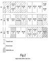
- Figure 2 illustrates a preferred operation of the BS, RS and MS in terms of its activity within each of the zones described in Table 1.
- Figure 3 indicates one particular realization of the proposed frame structure in terms of how different user types may be allocated for transmission or reception within the various zone types.
- a description of the zones that are used in this example is given in Table 2. Table 2. Description of example of zone usage within one cell.
- Link DL Zone Usage UL Zone Usage Comments (A) (1), (2), (5) (6), (7) MS and RS are spatially separated and therefore significant interference isolation exists. User does not support SDMA.
- (B) (1), (2), (3) (6), (9) MS and RS are spatially separated and therefore significant interference isolation exists. User does support SDMA.
- C (1), (2), (3), (5) (6), (7), (9) RS receives data in (3) and (7) and then transmits in (5) and (9) thereby enabling in-frame relaying.
- the BS can make use of all of the transmission resource all of the time to communicate with the RS and MS nodes in the network. This is enabled by reusing the transmission resource used on the RS to MS link for BS to MS communications. In order to effect this, and prevent such a reuse approach from causing excess interference, the BS must ensure that the users it communicates within this reuse zone (i.e. zones (5) & (9)) are sufficiently isolated from the users communicating with the RS. Thus, the BS essentially requires a mechanism to decide whether the users with which it communicates should be in the reuse zone (i.e. zones (5) & (9)) or the normal zone (i.e. zones (4) & (8)).
- Embodiments of the present invention may be implemented in hardware, or as software modules running on one or more processors, or on a combination thereof. That is, those skilled in the art will appreciate that a microprocessor or digital signal processor (DSP) may be used in practice to implement some or all of the functionality of a transmitter embodying the present invention.
- DSP digital signal processor
- the invention may also be embodied as one or more device or apparatus programs (e.g. computer programs and computer program products) for carrying out part or all of any of the methods described herein.
- Such programs embodying the present invention may be stored on computer-readable media, or could, for example, be in the form of one or more signals.
- Such signals may be data signals downloadable from an Internet website, or provided on a carrier signal, or in any other form.
Abstract
employing said format to transmit information along the path as two successive transmission signals, link by link, said signals being transmitted using different transmission windows of a particular such transmission interval.
Description
- Currently there exists significant interest in the use of multihop techniques in packet based radio and other communication systems, where it is purported that such techniques will enable both extension in coverage range and increase in system capacity (throughput).
- In a multi-hop communication system, communication signals are sent in a communication direction along a communication path (C) from a source apparatus to a destination apparatus via one or more intermediate apparatuses. Figure 4 illustrates a single-cell two-hop wireless communication system comprising a base station BS (known in the context of 3G communication systems as □node-B□NB) a relay node RN (also known as a relay station RS) and a user equipment UE (also known as mobile station MS). In the case where signals are being transmitted on the downlink (DL) from a base station to a destination user equipment (UE) via the relay node (RN), the base station comprises the source station (S) and the user equipment comprises the destination station (D). In the case where communication signals are being transmitted on the uplink (UL) from a user equipment (UE), via the relay node, to the base station, the user equipment comprises the source station and the base station comprises the destination station. The relay node is an example of an intermediate apparatus (I) and comprises: a receiver, operable to receive data from the source apparatus; and a transmitter, operable to transmit this data, or a derivative thereof, to the destination apparatus.
- Simple analogue repeaters or digital repeaters have been used as relays to improve or provide coverage in dead spots. They can either operate in a different transmission frequency band from the source station to prevent interference between the source transmission and the repeater transmission, or they can operate at a time when there is no transmission from the source station.
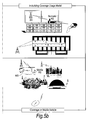
- Figure 5 illustrates a number of applications for relay stations. For fixed infrastructure, the coverage provided by a relay station may be □in-fill □ to allow access to the communication network for mobile stations which may otherwise be in the shadow of other objects or otherwise unable to receive a signal of sufficient strength from the base station despite being within the normal range of the base station. □ Range extension □is also shown, in which a relay station allows access when a mobile station is outside the normal data transmission range of a base station. One example of in-fill shown at the top right of Figure 5 is positioning of a nomadic relay station to allow penetration of coverage within a building that could be above, at, or below ground level.
- Other applications are nomadic relay stations which are brought into effect for temporary cover, providing access during events or emergencies/disasters. A final application shown in the bottom right of Figure 5 provides access to a network using a relay positioned on a vehicle.
- Relays may also be used in conjunction with advanced transmission techniques to enhance gain of the communications system as explained below.
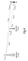
- It is known that the occurrence of propagation loss, or □pathloss□, due to the scattering or absorption of a radio communication as it travels through space, causes the strength of a signal to diminish. Factors which influence the pathloss between a transmitter and a receiver include: transmitter antenna height, receiver antenna height, carrier frequency, clutter type (urban, sub-urban, rural), details of morphology such as height, density, separation, terrain type (hilly, flat). The pathloss L (dB) between a transmitter and a receiver can be modelled by:

- Where d (metres) is the transmitter-receiver separation, b(db) and n are the pathloss parameters and the absolute pathloss is given by l = 10(L/10)
- The sum of the absolute path losses experienced over the indirect link SI + ID may be less than the pathloss experienced over the direct link SD. In other words it is possible for:

- Splitting a single transmission link into two shorter transmission segments therefore exploits the non-linear relationship between pathloss verses distance. From a simple theoretical analysis of the pathloss using equation (A), it can be appreciated that a reduction in the overall pathloss (and therefore an improvement, or gain, in signal strength and thus data throughput) can be achieved if a signal is sent from a source apparatus to a destination apparatus via an intermediate apparatus (e.g. relay node), rather than being sent directly from the source apparatus to the destination apparatus.
- If implemented appropriately, multi-hop communication systems can allow for a reduction in the transmit power of transmitters which facilitate wireless transmissions, leading to a reduction in interference levels as well as decreasing exposure to electromagnetic emissions. Alternatively, the reduction in overall pathloss can be exploited to improve the received signal quality at the receiver without an increase in the overall radiated transmission power required to convey the signal.
- Multi-hop systems are suitable for use with multi-carrier transmission. In a multi-carrier transmission system, such as FDM (frequency division multiplex), OFDM (orthogonal frequency division multiplex) or DMT (discrete multi-tone), a single data stream is modulated onto N parallel sub-carriers, each sub-carrier signal having its own frequency range. This allows the total bandwidth (i.e. the amount of data to be sent in a given time interval) to be divided over a plurality of sub-carriers thereby increasing the duration of each data symbol. Since each sub-carrier has a lower information rate, multi-carrier systems benefit from enhanced immunity to channel induced distortion compared with single carrier systems. This is made possible by ensuring that the transmission rate and hence bandwidth of each subcarrier is less than the coherence bandwidth of the channel. As a result, the channel distortion experienced on a signal subcarrier is frequency independent and can hence be corrected by a simple phase and amplitude correction factor. Thus the channel distortion correction entity within a multicarrier receiver can be of significantly lower complexity of its counterpart within a single carrier receiver when the system bandwidth is in excess of the coherence bandwidth of the channel.
- Orthogonal frequency division multiplexing (OFDM) is a modulation technique that is based on FDM. An OFDM system uses a plurality of sub-carrier frequencies which are orthogonal in a mathematical sense so that the sub-carriers □spectra may overlap without interference due to the fact they are mutually independent. The orthogonality of OFDM systems removes the need for guard band frequencies and thereby increases the spectral efficiency of the system. OFDM has been proposed and adopted for many wireless systems. It is currently used in Asymmetric Digital Subscriber Line (ADSL) connections, in some wireless LAN applications (such as WiFi devices based on the IEEE802.11a/g standard), and in wireless MAN applications such as WiMAX (based on the IEEE 802.16 standard). OFDM is often used in conjunction with channel coding, an error correction technique, to create coded orthogonal FDM or COFDM. COFDM is now widely used in digital telecommunications systems to improve the performance of an OFDM based system in a multipath environment where variations in the channel distortion can be seen across both subcarriers in the frequency domain and symbols in the time domain. The system has found use in video and audio broadcasting, such as DVB and DAB, as well as certain types of computer networking technology.
- In an OFDM system, a block of N modulated parallel data source signals is mapped to N orthogonal parallel sub-carriers by using an Inverse Discrete or Fast Fourier Transform algorithm (IDFT/IFFT) to form a signal known as an □OFDM symbol □in the time domain at the transmitter. Thus, an □OFDM symbol □is the composite signal of all N sub-carrier signals. An OFDM symbol can be represented mathematically as:

where Δf is the sub-carrier separation in Hz, Ts = 1/Δf is symbol time interval in seconds, and Cn are the modulated source signals. The sub-carrier vector in (1) onto which each of the source signals is modulated c ∈ Cn, C = (C0, C1..CN-1) is a vector of N constellation symbols from a finite constellation. At the receiver, the received time-domain signal is transformed back to frequency domain by applying Discrete Fourier Transform (DFT) or Fast Fourier Transform (FFT) algorithm. - OFDMA (Orthogonal Frequency Division Multiple Access) is a multiple access variant of OFDM. It works by assigning a subset of sub-carriers, to an individual user. This allows simultaneous transmission from several users leading to better spectral efficiency. However, there is still the issue of allowing bi-directional communication, that is, in the uplink and download directions, without interference.
- In order to enable bi-directional communication between two nodes, two well known different approaches exist for duplexing the two (forward or download and reverse or uplink) communication links to overcome the physical limitation that a device cannot simultaneously transmit and receive on the same resource medium. The first, frequency division duplexing (FDD), involves operating the two links simultaneously but on different frequency bands by subdividing the transmission medium into two distinct bands, one for forward link and the other for reverse link communications. The second, time division duplexing (TDD), involves operating the two links on the same frequency band, but subdividing the access to the medium in time so that only the forward or the reverse link will be utilizing the medium at any one point in time. Both approaches (TDD & FDD) have their relative merits and are both well used techniques for single hop wired and wireless communication systems. For example the IEEE802.16 standard incorporates both an FDD and TDD mode.
- As an example, Figure 6 illustrates the single hop TDD frame structure used in the OFDMA physical layer mode of the IEEE802.16 standard (WiMAX).
- Each frame is divided into DL and UL subframes, each being a discrete transmission interval. They are separated by Transmit/Receive and Receive/Transmit Transition Guard interval (TTG and RTG respectively). Each DL subframe starts with a preamble followed by the Frame Control Header (FCH), the DL-MAP, and the UL-MAP.
- The FCH contains the DL Frame Prefix (DLFP) to specify the burst profile and the length of the DL-MAP. The DLFP is a data structure transmitted at the beginning of each frame and contains information regarding the current frame; it is mapped to the FCH.
- Simultaneous DL allocations can be broadcast, multicast and unicast and they can also include an allocation for another BS rather than a serving BS. Simultaneous ULs can be data allocations and ranging or bandwidth requests.
- This patent application is one of a set of ten UK patent applications filed on the same date by the same applicant with agent reference numbers P106752GBOO, P106753GB00, P106754GB00, P106772GB00, P106773GB00, P106795GB00, P106796GB00, P106797GBOO, P106798GBOO, and P106799GBOO, describing interrelated inventions proposed by the present inventors relating to communication techniques. The entire contents of each of the other nine applications is incorporated herein by way of reference thereto and copies of each of the other nine applications are filed herewith.
- When a node is required to support two independent links to two different nodes, e.g. a relay station communicating with a basestation and a mobile, the existing TDD or FDD frame structures require some modification in order to make realization of the relay practical.
- The invention is defined in the independent claims, to which reference should now be made. Advantageous embodiments are set out in the sub claims.
- Preferred features of the present invention will now be described, purely by way of example, with reference to the accompanying drawings, in which:-
- Figure 1 shows a frame structure;
- Figure 2 shows node activity within each zone;
- Figure 3 shows an example of zone usage within one cell;
- Figure 4 shows a single-cell two-hop wireless communication system;
- Figure 5 shows applications of relay stations; and
- Figure 6 shows a single hop TDD frame structure used in the OFDMA physical layer mode of the IEEE 802.16 standard.
- Embodiments of the invention provide a frame structure (format) for a multihop communication system that is an extension of the standard TDD frame structure. The proposed frame structure has numerous benefits, as described later in this description.
- The proposed frame structure is designed for the case that the control information originating from the head node that controls the overall medium access is receivable by all subordinate nodes operating in the network. It is further designed in a manner that enables legacy single hop TDD mobile devices that have no knowledge of a relay station to operate within the new relaying enabled system.
- If control information is not receivable from the head node (or source apparatus) then an extra frame period is required for two-hop transmission. This is because control information sent by the source apparatus to the intermediate apparatus cannot then be received by the destination apparatus in the same frame. The destination apparatus (especially a legacy apparatus) will be designed to receive such control information at the beginning of the frame and therefore an extra frame period is required for the intermediate apparatus to transmit the control information on to the source at the beginning of the frame (in the preamble) and then transmit the data. Thus a frame latency of 1 is incurred.
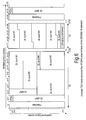
- A preferred frame structure is shown in Figure 1.
- It is composed of a number of transmission and reception zones for both the downlink and uplink sub-frames. The zone types are either:
- B
- Broadcast of control related information such as: synchronization sequences, commands, information and details of the structure or layout of the frame.
- C
- Dedicated control information that is transmitted in a non-broadcast zone (i.e. either to individual or a group of receivers)
- T
- Dedicated user-data (transport) transmission
- The 9 different zones identified in Figure 1 are described in Table 1.
Table 1. Description of the zones. Zone Number Label Description 1 P Preamble or synchronization sequence transmissions for cell identification 2 MAP Frame format description (zone boundaries, allocations within the zones, etc) 3 BS-RS / BS-MS BS to RS transmission zone. Can also be used for BS to MS transmission if spatial division multiple access is supported (i.e. the same transmission resource can be used to communicate with more than one entity) 4 BS-MS BS to MS transmission zone. RS is not active during this period, it is processing any received information and turning around prior to transmission. 5 BS-MS / RS-MS RS to MS transmission zone. Can also be used by the BS to transmitted to MSs that do not experience significant levels of interference from RS transmissions. 6 MS-BS / MS-RS MS control information transmission zone. Information can be received by both the RS and the BS. Control information can be information or requests from the MS. 7 MS-BS / MS-RS MS to RS transmission zone. Can also be used by MSs who do not cause interference to the RS to transmit to the BS. 8 MS-BS MS to BS transmission zone. RS is not actively transmitting or receiving during this period; it is processing any received information prior to turning around. 9 RS-BS / MS-BS RS to BS transmission zone. Can also be used for MS to BS transmission if spatial division multiple access is supported (i.e. the same transmission resource can be used to communicate with more than one entity) - Figure 2 illustrates a preferred operation of the BS, RS and MS in terms of its activity within each of the zones described in Table 1.
- Figure 3 indicates one particular realization of the proposed frame structure in terms of how different user types may be allocated for transmission or reception within the various zone types.
- In this case there are five link types identified (A-E), as illustrated in Figure 3. A description of the zones that are used in this example is given in Table 2.
Table 2. Description of example of zone usage within one cell. Link DL Zone Usage UL Zone Usage Comments (A) (1), (2), (5) (6), (7) MS and RS are spatially separated and therefore significant interference isolation exists. User does not support SDMA. (B) (1), (2), (3) (6), (9) MS and RS are spatially separated and therefore significant interference isolation exists. User does support SDMA. (C) (1), (2), (3), (5) (6), (7), (9) RS receives data in (3) and (7) and then transmits in (5) and (9) thereby enabling in-frame relaying. (D) (1), (2), (5) (6), (7) MS communicates with BS via RS. Transmission to the RS happens at the beginning of the UL subframe (7) to allow sufficient RS relay processing time. (E) (1), (2), (4) (6), (8) MSs that communicate directly with the BS that are not isolated from the RS use zones (4) & (8) to prevent RS interference from impairing link performance. - One of the key advantages of adopting the proposed frame structure of invention embodiments is that the BS can make use of all of the transmission resource all of the time to communicate with the RS and MS nodes in the network. This is enabled by reusing the transmission resource used on the RS to MS link for BS to MS communications. In order to effect this, and prevent such a reuse approach from causing excess interference, the BS must ensure that the users it communicates within this reuse zone (i.e. zones (5) & (9)) are sufficiently isolated from the users communicating with the RS. Thus, the BS essentially requires a mechanism to decide whether the users with which it communicates should be in the reuse zone (i.e. zones (5) & (9)) or the normal zone (i.e. zones (4) & (8)).
- There are numerous algorithms that can be conceived to form such a mechanism, some are listed below:
- 1. Ask the MS to perform a carrier-to-interference-plus-noise (CINR) measurement on the BS transmission during the reuse zone and during the normal zone. If the CINR is much higher in the normal zone then allocate the user to the normal zone. If the CINR is similar, then allocate the user to the reuse zone.
- 2. Start with all users in the normal zone. If the normal zone becomes fully loaded and cannot accommodate more users without the risk of imposing a reduction on the quality of service new and existing users will experience, then identify candidate users to move from the normal zone to the reuse zone. If subsequently the reported CINR for a user communicating with the BS in the reuse zone falls below a particular threshold then move that to the normal zone.
- In summary the benefits of invention embodiments are:
- o Enables the construction and operation of simple, low cost relays that do not need to generate any control information or perform scheduling
- o Maximises spectral efficiency by ensuring that the BS does not have any time in the frame when it is idle
- o Minimises latency by enabling two-hop relaying to occur within one frame
- o Enables the system to potentially provide transparent operation to a legacy single-hop TDD users
- o The possibility to further improve spectral efficiency through using SDMA based techniques to enable the same transmission resource (frequency & time) to be used between the BS and the RSs and MSs within a cell.
- o Provides a mechanism to enable reuse of the RS-MS communication zone by the BS to communicate directly with MSs that will not cause a degradation in RS-MS link performance by performing such communications.
- Embodiments of the present invention may be implemented in hardware, or as software modules running on one or more processors, or on a combination thereof. That is, those skilled in the art will appreciate that a microprocessor or digital signal processor (DSP) may be used in practice to implement some or all of the functionality of a transmitter embodying the present invention. The invention may also be embodied as one or more device or apparatus programs (e.g. computer programs and computer program products) for carrying out part or all of any of the methods described herein. Such programs embodying the present invention may be stored on computer-readable media, or could, for example, be in the form of one or more signals. Such signals may be data signals downloadable from an Internet website, or provided on a carrier signal, or in any other form.
Claims (33)
- A transmission method for use in a two-hop wireless communication system, the system comprising a source apparatus, a destination apparatus and an intermediate apparatus, said source apparatus being operable to transmit information along two links forming a communication path extending from the source apparatus to the destination apparatus via the intermediate apparatus, and the intermediate apparatus being operable to receive information from the source apparatus and to transmit the received information to the destination apparatus, the system having access to a time-frequency format for use in assigning available transmission frequency bandwidth during a discrete transmission interval, said format defining a plurality of transmission windows within such an interval, each window occupying a different part of that interval and having a frequency bandwidth profile within said available transmission frequency bandwidth over its part of that interval, each said window being assignable for such a transmission interval to said source or intermediate apparatus for use in transmission, the method comprising:employing said format to transmit information along the path as two successive transmission signals, link by link, said signals being transmitted using different transmission windows of a particular such transmission interval.
- The transmission method according to claim 1, wherein the frequency bandwidth profiles of at least two of said transmission windows encompass a common part of the available transmission frequency bandwidth.
- The transmission method according to claim 1 or 2, wherein the frequency bandwidth profiles of at least two said transmission windows extend over substantially the entire transmission frequency bandwidth for the respective interval parts.
- The transmission method according to any preceding claim, further comprising:prior to said transmission, employing said format to assign a particular transmission window of the particular transmission interval to the source apparatus for transmission of the information to the intermediate apparatus, and to assign a subsequent transmission window of the particular transmission interval to the intermediate apparatus for transmission of the information to the destination apparatus.
- The transmission method according to any preceding claim, further comprising employing the format to assign a control window to the source apparatus for transmission of control information to the intermediate apparatus.
- The transmission method according to claim 5 when read as appended to claim 4, wherein said control window occupies a part of the particular transmission interval preceding the part of the particular transmission interval occupied by the particular transmission window.
- The transmission method according to any one of claims 4 to 6, wherein said particular and subsequent transmission windows of the particular transmission interval are either side in time of a further transmission window of that interval.
- The transmission method according to claim 7, further comprising:performing processing in said intermediate apparatus during the part of the particular transmission interval corresponding to the further transmission window, so as to configure the information for transmission in the subsequent transmission window based upon the information received in the particular transmission window.
- The transmission method according to claim 7 or 8, wherein said communication path is an indirect communication path, and wherein the system comprises at least a further destination apparatus, and wherein said source apparatus is operable to transmit information directly to the or each further destination apparatus along a corresponding single link forming a direct communication path.
- The transmission method according to claim 9, comprising:employing said further transmission window to transmit information from the source apparatus to a said further destination apparatus along such a direct communication path, so that information is transmitted from the source apparatus during said processing in the intermediate apparatus.
- The transmission method according to claim 9 or 10, comprising:employing said particular transmission window to transmit information from the source apparatus to a said further destination apparatus along such a direct communication path, so that information is transmitted from the source apparatus to both said intermediate apparatus and said further destination apparatus during the part of the particular transmission interval corresponding to the particular transmission window.
- The transmission method according any one of claims 9 to 11, comprising:employing said subsequent transmission window to transmit information from the source apparatus to a said further destination apparatus along such a direct communication path, so that information is transmitted from said intermediate apparatus to said destination apparatus and from the source apparatus to said further destination apparatus during the part of the subsequent transmission interval corresponding to the subsequent transmission window.
- The transmission method according to claim 7 or 8, wherein said communication path is an indirect communication path, and wherein the system comprises at least a further source apparatus, and wherein the or each further source apparatus is operable to transmit information directly to the destination apparatus along a corresponding single link forming a direct communication path.
- The transmission method according to claim 13, comprising:employing said further transmission window to transmit information from a said further source apparatus to said destination apparatus along such a direct communication path, so that information is transmitted from that further source apparatus during said processing in the intermediate apparatus.
- The transmission method according to claim 13 or 14, comprising:employing said particular transmission window to transmit information from a said further source apparatus to said destination apparatus along such a direct communication path, so that information is transmitted from the source apparatus to said intermediate apparatus and from that further source apparatus to said further destination apparatus during the part of the particular transmission interval corresponding to the particular transmission window.
- The transmission method according any one of claims 13 to 15, comprising:employing said subsequent transmission window to transmit information from a said further source apparatus to said destination apparatus along such a direct communication path, so that information is transmitted from said intermediate apparatus to said destination apparatus and from that further source apparatus to said destination apparatus during the part of the subsequent transmission interval corresponding to the subsequent transmission window.
- The transmission method according to any one of claims 7 to 16, comprising employing a space division multiple access technique in one or more of said transmission windows of the particular transmission interval.
- The transmission method according to any preceding claim, wherein the time-frequency format is a format for a downlink or uplink sub-frame in a time-divisionduplex communication system.
- The transmission method according to any preceding claim, wherein said system is an OFDM or OFDMA system, and wherein the time-frequency format is a format for an OFDM or OFDMA downlink or uplink sub-frame of an OFDM or OFDMA time-division-duplex frame.
- The transmission method according to any preceding claim, wherein each said discrete transmission interval is a sub-frame period.
- The transmission method according to any preceding claim, wherein each said transmission window comprises a region in an OFDM or OFDMA frame structure.
- The transmission method according to any preceding claim, wherein each said transmission window comprises a zone in an OFDM or OFDMA frame structure.
- The transmission method according to any preceding claim, wherein the or each source apparatus is a base station.
- The transmission method according to any preceding claim, wherein the or each source apparatus is a user terminal.
- The transmission method according to any preceding claim, wherein the or each destination apparatus is a base station.
- The transmission method according to any preceding claim, wherein the or each destination apparatus is a user terminal.
- The transmission method according to any preceding claim, wherein the or each intermediate apparatus is a relay station.
- A transmission method for use in a two-hop wireless communication system, the system comprising a source apparatus, a destination apparatus and an intermediate apparatus, said source apparatus being operable to transmit information along two links forming a communication path extending from the source apparatus to the destination apparatus via the intermediate apparatus, and the intermediate apparatus being operable to receive information from the source apparatus and to transmit the received information to the destination apparatus, the system having access to a time-frequency format for use in assigning available transmission frequency bandwidth during a discrete transmission interval, said format defining a plurality of transmission windows within such an interval, each window occupying a different part of that interval and having a frequency bandwidth profile within said available transmission frequency bandwidth over its part of that interval, each said window being assignable for such a transmission interval to said source or intermediate apparatus for use in transmission, the method comprising:employing said format to transmit data and control information together as a transmission signal along the link from the source apparatus to the intermediate apparatus and to transmit data information as a transmission signal along the link from the intermediate apparatus to the destination apparatus, said signals being transmitted using respective transmission windows of two such transmission intervals.
- A two-hop wireless communication system, the system comprising:a source apparatus, a destination apparatus and an intermediate apparatus, said source apparatus being operable to transmit information along two links forming a communication path extending from the source apparatus to the destination apparatus via the intermediate apparatus, and the intermediate apparatus being operable to receive information from the source apparatus and to transmit the received information to the destination apparatus;format-access means operable to access a time-frequency format for use in assigning available transmission frequency bandwidth during a discrete transmission interval, said format defining a plurality of transmission windows within such an interval, each window occupying a different part of that interval and having a frequency bandwidth profile within said available transmission frequency bandwidth over its part of that interval, each said window being assignable for such a transmission interval to said source or intermediate apparatus for use in transmission; andtransmission means operable to employ said format to transmit information along the relayed path as two successive transmission signals, link by link, using different transmission windows of a particular such transmission interval.
- A suite of computer programs which, when executed on computing devices of a two-hop wireless communication system, causes the system to carry out a transmission method, the system comprising a source apparatus, a destination apparatus and an intermediate apparatus, said source apparatus being operable to transmit information along two links forming a communication path extending from the source apparatus to the destination apparatus via the intermediate apparatus, and the intermediate apparatus being operable to receive information from the source apparatus and to transmit the received information to the destination apparatus, the system having access to a time-frequency format for use in assigning available transmission frequency bandwidth during a discrete transmission interval, said format defining a plurality of transmission windows within such an interval, each window occupying a different part of that interval and having a frequency bandwidth profile within said available transmission frequency bandwidth over its part of that interval, each said window being assignable for such a transmission interval to said source or intermediate apparatus for use in transmission, the method comprising:employing said format to transmit information along the relayed path as two successive transmission signals, link by link, said signals being transmitted using different transmission windows of a particular such transmission interval.
- An intermediate apparatus for use in a two-hop wireless communication system, the system further comprising a source apparatus, and a destination apparatus, said source apparatus being operable to transmit information along a series of links forming a communication path extending from the source apparatus to the destination apparatus via the intermediate apparatus, and the intermediate apparatus being operable to receive information from a previous apparatus along the path and to transmit the received information to a subsequent apparatus along the path the intermediate apparatus comprising:format-access means operable to access a time-frequency format for use in assigning available transmission frequency bandwidth during a discrete transmission interval, said format defining a plurality of transmission windows within such an interval, each window occupying a different part of that interval and having a frequency bandwidth profile within said available transmission frequency bandwidth over its part of that interval, each said window being assignable for such a transmission interval to said source or said intermediate apparatus for use in transmission; andtransceiver means operable to employ said format for one such transmission interval to receive information in an available transmission window of said interval and to transmit said information in a later available transmission window during the same said transmission interval such that said information passes along the two links in a single transmission interval.
- A transmission method for use in an intermediate apparatus of a two-hop wireless communication system, the system further comprising a source apparatus and a destination apparatus, said source apparatus being operable to transmit information along two links forming a communication path extending from the source apparatus to the destination apparatus via the intermediate apparatus, and the intermediate apparatus being operable to receive information from the source apparatus and to transmit the received information to the destination apparatus, the intermediate apparatus having access to a time-frequency format for use in assigning available transmission frequency bandwidth during a discrete transmission interval, said format defining a plurality of transmission windows within such an interval, each window occupying a different part of that interval and having a frequency bandwidth profile within said available transmission frequency bandwidth over its part of that interval, each said window being assignable for such a transmission interval to said source or intermediate apparatus for use in transmission, the method comprising:employing said format for one such transmission method to receive information in an available window of said interval and to transmit said information in a later available window during the same transmission interval such that said information passes along the two links in a single transmission interval.
- A computer program, which when executed on a computing device of an intermediate apparatus in a two-hop wireless communication system, causes the intermediate apparatus to carry out a transmission method, the system further comprising a source apparatus and a destination apparatus, said source apparatus being operable to transmit information along two links forming a communication path extending from the source apparatus to the destination apparatus via the intermediate apparatus, and the intermediate apparatus being operable to receive information from the source apparatus and to transmit the received information to the destination apparatus, the intermediate apparatus having access to a time-frequency format for use in assigning available transmission frequency bandwidth during a discrete transmission interval, said format defining a plurality of transmission windows within such an interval, each window occupying a different part of that interval and having a frequency bandwidth profile within said available transmission frequency bandwidth over its part of that interval, each said window being assignable for such a transmission interval to said source or intermediate apparatus for use in transmission, the method comprising:employing said format for one such transmission method to receive information in an available window of said interval and to transmit said information in a later available window during the same transmission interval such that said information passes along the two links in a single transmission interval.
Priority Applications (1)
| Application Number | Priority Date | Filing Date | Title |
|---|---|---|---|
| EP09179735A EP2178325B1 (en) | 2006-08-18 | 2007-07-31 | Multi-hop wireless communication |
Applications Claiming Priority (1)
| Application Number | Priority Date | Filing Date | Title |
|---|---|---|---|
| GB0616477A GB2440982A (en) | 2006-08-18 | 2006-08-18 | Wireless multi-hop communication system |
Related Child Applications (1)
| Application Number | Title | Priority Date | Filing Date |
|---|---|---|---|
| EP09179735.7 Division-Into | 2009-12-17 |
Publications (3)
| Publication Number | Publication Date |
|---|---|
| EP1890416A2 true EP1890416A2 (en) | 2008-02-20 |
| EP1890416A3 EP1890416A3 (en) | 2010-05-19 |
| EP1890416B1 EP1890416B1 (en) | 2014-01-08 |
Family
ID=37081239
Family Applications (2)
| Application Number | Title | Priority Date | Filing Date |
|---|---|---|---|
| EP07113531.3A Expired - Fee Related EP1890416B1 (en) | 2006-08-18 | 2007-07-31 | Multi-hop wireless communication |
| EP09179735A Expired - Fee Related EP2178325B1 (en) | 2006-08-18 | 2007-07-31 | Multi-hop wireless communication |
Family Applications After (1)
| Application Number | Title | Priority Date | Filing Date |
|---|---|---|---|
| EP09179735A Expired - Fee Related EP2178325B1 (en) | 2006-08-18 | 2007-07-31 | Multi-hop wireless communication |
Country Status (7)
| Country | Link |
|---|---|
| US (2) | US9356807B2 (en) |
| EP (2) | EP1890416B1 (en) |
| JP (2) | JP4992606B2 (en) |
| KR (2) | KR100996034B1 (en) |
| CN (2) | CN101127558A (en) |
| GB (1) | GB2440982A (en) |
| TW (2) | TW201029362A (en) |
Cited By (1)
| Publication number | Priority date | Publication date | Assignee | Title |
|---|---|---|---|---|
| US8532016B2 (en) | 2008-08-22 | 2013-09-10 | Fujitsu Limited | Methods and apparatus for operating a wireless communications system |
Families Citing this family (22)
| Publication number | Priority date | Publication date | Assignee | Title |
|---|---|---|---|---|
| EP1734667B1 (en) | 2005-06-17 | 2011-08-10 | Fujitsu Limited | Multi-hop communication system |
| EP1734665B1 (en) | 2005-06-17 | 2011-08-10 | Fujitsu Limited | Multi-hop communication system |
| DE602005009340D1 (en) | 2005-06-17 | 2008-10-09 | Fujitsu Ltd | Power control in the multi-way communication system |
| EP1734666A1 (en) | 2005-06-17 | 2006-12-20 | Fujitsu Limited | Resource management in multi-hop communication system |
| GB0616476D0 (en) | 2006-08-18 | 2006-09-27 | Fujitsu Ltd | Communication systems |
| TW201028024A (en) * | 2006-08-18 | 2010-07-16 | Fujitsu Ltd | Communication systems |
| GB2440986A (en) * | 2006-08-18 | 2008-02-20 | Fujitsu Ltd | Wireless multi-hop communication system |
| GB2440981A (en) * | 2006-08-18 | 2008-02-20 | Fujitsu Ltd | Wireless multi-hop communication system |
| GB2441574A (en) * | 2006-09-08 | 2008-03-12 | Fujitsu Ltd | Network entry to a multi-hop wireless communication system |
| GB0619454D0 (en) | 2006-10-02 | 2006-11-08 | Fujitsu Ltd | Communication systems |
| GB0619455D0 (en) | 2006-10-02 | 2006-11-08 | Fujitsu Ltd | Communication system |
| GB2443464A (en) | 2006-11-06 | 2008-05-07 | Fujitsu Ltd | Signalling in a multi-hop communication systems |
| GB2447883A (en) | 2007-03-02 | 2008-10-01 | Fujitsu Ltd | Bandwidth allocation in multi-hop wireless communication systems |
| GB2447635A (en) | 2007-03-19 | 2008-09-24 | Fujitsu Ltd | Scheduling qos communications between nodes within a predetermined time unit in wimax systems |
| EP2106074B1 (en) * | 2008-03-27 | 2010-09-22 | Fujitsu Limited | Wireless communication systems |
| US8059622B2 (en) * | 2008-09-04 | 2011-11-15 | Intel Corporation | Multi-radio platform and method for coordinating activities between a broadband wireless access network transceiver and co-located transceiver |
| KR101668704B1 (en) * | 2008-09-05 | 2016-10-28 | 엘지전자 주식회사 | Downlink silent period for positioning |
| CN101521922B (en) * | 2009-03-25 | 2012-11-07 | 华为技术有限公司 | Multiplexing area switching method and server |
| KR101877754B1 (en) | 2012-11-26 | 2018-07-13 | 삼성전자주식회사 | Communication method for transmitting and receiving channel information in a multi-hop network and terminals thereof |
| CN104053236B (en) * | 2013-03-11 | 2018-11-06 | 中兴通讯股份有限公司 | A kind of resource allocation methods, access point and relay access point |
| US11405924B2 (en) * | 2017-12-08 | 2022-08-02 | Mediatek Singapore Pte. Ltd. | Communication interference mitigation systems and methods |
| CN111356201B (en) * | 2018-12-20 | 2022-04-15 | 大唐移动通信设备有限公司 | Method and device for grouping great coverage and network node |
Citations (2)
| Publication number | Priority date | Publication date | Assignee | Title |
|---|---|---|---|---|
| WO2005067173A1 (en) * | 2003-12-30 | 2005-07-21 | Nokia Corporation | Communication system using relay base stations with asymmetric data links |
| WO2006045499A1 (en) * | 2004-10-20 | 2006-05-04 | T-Mobile International Ag & Co Kg | Cellular wide-area radio communications system with relay-enhanced cells |
Family Cites Families (59)
| Publication number | Priority date | Publication date | Assignee | Title |
|---|---|---|---|---|
| DE3403715A1 (en) | 1984-02-03 | 1985-08-08 | Licentia Patent-Verwaltungs-Gmbh, 6000 Frankfurt | DIGITAL CELL RADIO SYSTEM WITH TIME MULTIPLEX |
| JPH0530000A (en) * | 1991-07-18 | 1993-02-05 | Fujitsu Ltd | Mobile body communication system |
| EP0566551B1 (en) * | 1992-04-17 | 1999-08-04 | Telefonaktiebolaget L M Ericsson | Mobile assisted handover using CDMA |
| JP2661533B2 (en) * | 1993-12-27 | 1997-10-08 | 日本電気株式会社 | Channel allocation method for mobile communication system |
| US5719868A (en) * | 1995-10-05 | 1998-02-17 | Rockwell International | Dynamic distributed, multi-channel time division multiple access slot assignment method for a network of nodes |
| US6049593A (en) * | 1997-01-17 | 2000-04-11 | Acampora; Anthony | Hybrid universal broadband telecommunications using small radio cells interconnected by free-space optical links |
| US6285857B1 (en) * | 1997-05-01 | 2001-09-04 | At&T Corp. | Multi-hop telecommunications system and method |
| EP0926905B1 (en) * | 1997-06-16 | 2010-08-11 | Mitsubishi Denki Kabushiki Kaisha | Mobile communication system |
| US6236647B1 (en) | 1998-02-24 | 2001-05-22 | Tantivy Communications, Inc. | Dynamic frame size adjustment and selective reject on a multi-link channel to improve effective throughput and bit error rate |
| DE69938979D1 (en) * | 1998-04-23 | 2008-08-07 | Mitsubishi Electric Corp | System and transmitter used in a mobile radio communication system for monitoring frequencies in another system |
| JP2954570B1 (en) | 1998-06-02 | 1999-09-27 | 株式会社次世代デジタルテレビジョン放送システム研究所 | Frequency selective interference correction device |
| US6370384B1 (en) * | 1998-07-30 | 2002-04-09 | Airnet Communications Corporation | Frequency re-use planning for wireless communications system using wireless translating repeaters |
| KR100272431B1 (en) * | 1998-09-03 | 2000-11-15 | 김영환 | Device for expanding coverage of cdma mobile communication system and method thereof |
| US7006530B2 (en) * | 2000-12-22 | 2006-02-28 | Wi-Lan, Inc. | Method and system for adaptively obtaining bandwidth allocation requests |
| US7158784B1 (en) | 2000-03-31 | 2007-01-02 | Aperto Networks, Inc. | Robust topology wireless communication using broadband access points |
| US6701129B1 (en) * | 2000-09-27 | 2004-03-02 | Nortel Networks Limited | Receiver based adaptive modulation scheme |
| US6961368B2 (en) * | 2001-01-26 | 2005-11-01 | Ericsson Inc. | Adaptive antenna optimization network |
| US7047016B2 (en) * | 2001-05-16 | 2006-05-16 | Qualcomm, Incorporated | Method and apparatus for allocating uplink resources in a multiple-input multiple-output (MIMO) communication system |
| DE60117202D1 (en) * | 2001-09-03 | 2006-04-20 | St Microelectronics Nv | A method and apparatus for estimating the speed of a mobile terminal in a wireless communication system |
| CA2415132C (en) * | 2001-12-28 | 2007-07-03 | Ntt Docomo, Inc. | Radio communication system, base station, relay station, mobile station, and packet transmission control method |
| US20030129982A1 (en) * | 2002-01-04 | 2003-07-10 | Patrick Perini | Soft handoff in a wireless communication system |
| GB0200237D0 (en) | 2002-01-07 | 2002-02-20 | Imec Inter Uni Micro Electr | Wireless cellular network architecture |
| US7096274B1 (en) | 2002-02-12 | 2006-08-22 | 3Com Corporation | Optimum frame size predictor for wireless Local Area Network |
| KR100509687B1 (en) * | 2002-02-15 | 2005-08-23 | 주식회사 위다스 | Apparatus for testing isolation status in RF repeater and method thereof |
| JP2004040568A (en) * | 2002-07-04 | 2004-02-05 | Denso Corp | Radio communications terminal |
| US7580394B2 (en) * | 2002-11-27 | 2009-08-25 | Nokia Corporation | System and method for collision-free transmission scheduling in a network |
| US20040109428A1 (en) * | 2002-12-09 | 2004-06-10 | Srikanth Krishnamurthy | Method and apparatus for resource allocation for multiple traffic classes in wireless ad-hoc networks |
| US7583619B2 (en) * | 2002-12-16 | 2009-09-01 | Nortel Networks Limited | Wireless access communications network |
| WO2004059882A1 (en) * | 2002-12-25 | 2004-07-15 | Fujitsu Limited | Radio communication system, relay apparatus and mobile terminal |
| US20050157681A1 (en) * | 2003-02-26 | 2005-07-21 | Yoshiharu Tajima | Diversity handover method, control station and mobile terminal device in mobile communications |
| US7218891B2 (en) * | 2003-03-31 | 2007-05-15 | Nortel Networks Limited | Multi-hop intelligent relaying method and apparatus for use in a frequency division duplexing based wireless access network |
| US7027827B2 (en) * | 2003-05-19 | 2006-04-11 | Motorola, Inc. | Method and apparatus for channel sharing between multiple communication systems |
| JP4564012B2 (en) | 2003-05-28 | 2010-10-20 | テレフオンアクチーボラゲット エル エム エリクソン(パブル) | Method and system for a wireless communication network utilizing relay |
| US7313399B2 (en) * | 2003-06-05 | 2007-12-25 | Millennial Net, Inc. | Protocol for configuring a wireless network |
| US7903538B2 (en) * | 2003-08-06 | 2011-03-08 | Intel Corporation | Technique to select transmission parameters |
| US7400856B2 (en) * | 2003-09-03 | 2008-07-15 | Motorola, Inc. | Method and apparatus for relay facilitated communications |
| WO2006000091A1 (en) | 2004-06-24 | 2006-01-05 | Nortel Networks Limited | Preambles in ofdma system |
| JP2006033207A (en) | 2004-07-14 | 2006-02-02 | Nec Corp | Position information providing system, radio base station device, position information providing method used for both, and program thereof |
| US8019352B2 (en) | 2004-07-23 | 2011-09-13 | Wireless Valley Communications, Inc. | System, method, and apparatus for determining and using the position of wireless devices or infrastructure for wireless network enhancements |
| US20060029017A1 (en) * | 2004-07-26 | 2006-02-09 | Beceem Communications Inc. | Method and system for transmitting training information in a block transmission system |
| US7864659B2 (en) * | 2004-08-02 | 2011-01-04 | Interdigital Technology Corporation | Quality control scheme for multiple-input multiple-output (MIMO) orthogonal frequency division multiplexing (OFDM) systems |
| JP4494134B2 (en) * | 2004-09-01 | 2010-06-30 | Kddi株式会社 | Wireless communication system, relay station apparatus and base station apparatus |
| DE602004006624T2 (en) | 2004-09-13 | 2008-01-31 | Alcatel Lucent | Estimation of the transmission quality in a radio network |
| JP4420218B2 (en) * | 2004-09-13 | 2010-02-24 | 日本電気株式会社 | Relay node installation point selection method / program / recording medium / device, base station, multi-hop network system |
| EP1803316B1 (en) * | 2004-10-21 | 2015-03-04 | Panasonic Corporation | System and method for relaying in multi-hop cellular networks |
| KR100810290B1 (en) * | 2004-12-14 | 2008-03-07 | 삼성전자주식회사 | Method and system for allocation data burst in a wireless communication system |
| KR100584409B1 (en) | 2004-12-29 | 2006-05-26 | 삼성전자주식회사 | Relay commonication method for ofdma-based cellular communication system |
| US8644130B2 (en) | 2005-03-18 | 2014-02-04 | Samsung Electronics Co., Ltd. | System and method for subcarrier allocation in a wireless multihop relay network |
| US7486928B2 (en) * | 2005-04-14 | 2009-02-03 | Kddi Corporation | Methods and apparatus for wireless communications |
| US7813695B2 (en) | 2005-05-06 | 2010-10-12 | Telefonaktiebolaget L M Ericsson (Publ) | Mobile assisted relay selection in a telecommunications system |
| JP2006319676A (en) * | 2005-05-12 | 2006-11-24 | Oki Electric Ind Co Ltd | Frame transmitting method, topology acquiring method and radio communication system |
| KR100855225B1 (en) * | 2005-09-28 | 2008-08-29 | 삼성전자주식회사 | Apparatus and method for communicating frame data in a multi-hop relay broadband wireless access communication system |
| KR100615139B1 (en) * | 2005-10-18 | 2006-08-22 | 삼성전자주식회사 | Method and apparatus for allocating transmission period in wireless telecommunication system and therefor system |
| JP2007129726A (en) | 2005-11-04 | 2007-05-24 | Samsung Electronics Co Ltd | Apparatus and method for supporting multilink by grouping multihop in cellular network of multihop relay system |
| KR100853422B1 (en) | 2006-01-03 | 2008-08-21 | 삼성전자주식회사 | Method for requesting and allocating of upstream bandwidth in a multi-hop relay broadband wireless access communication system |
| US20070217353A1 (en) * | 2006-03-20 | 2007-09-20 | Motorola, Inc. | Method and Apparatus for Transmitting Data Within a Multi-Hop Communication System |
| GB2440984A (en) * | 2006-08-18 | 2008-02-20 | Fujitsu Ltd | Wireless multi-hop communication system |
| GB2440985A (en) * | 2006-08-18 | 2008-02-20 | Fujitsu Ltd | Wireless multi-hop communication system |
| JP5034369B2 (en) * | 2006-08-18 | 2012-09-26 | 富士通株式会社 | Wireless communication control method |
-
2006
- 2006-08-18 GB GB0616477A patent/GB2440982A/en not_active Withdrawn
-
2007
- 2007-07-31 EP EP07113531.3A patent/EP1890416B1/en not_active Expired - Fee Related
- 2007-07-31 TW TW099110353A patent/TW201029362A/en unknown
- 2007-07-31 TW TW096127955A patent/TWI356645B/en not_active IP Right Cessation
- 2007-07-31 EP EP09179735A patent/EP2178325B1/en not_active Expired - Fee Related
- 2007-08-17 CN CNA2007101419864A patent/CN101127558A/en active Pending
- 2007-08-17 CN CN2010101222646A patent/CN101820311B/en not_active Expired - Fee Related
- 2007-08-17 KR KR1020070083023A patent/KR100996034B1/en not_active IP Right Cessation
- 2007-08-17 US US11/840,570 patent/US9356807B2/en active Active
- 2007-08-20 JP JP2007214172A patent/JP4992606B2/en not_active Expired - Fee Related
-
2009
- 2009-10-22 KR KR1020090100897A patent/KR101041639B1/en not_active IP Right Cessation
-
2010
- 2010-02-05 US US12/701,191 patent/US8594009B2/en not_active Expired - Fee Related
- 2010-03-12 JP JP2010056535A patent/JP5062274B2/en not_active Expired - Fee Related
Patent Citations (2)
| Publication number | Priority date | Publication date | Assignee | Title |
|---|---|---|---|---|
| WO2005067173A1 (en) * | 2003-12-30 | 2005-07-21 | Nokia Corporation | Communication system using relay base stations with asymmetric data links |
| WO2006045499A1 (en) * | 2004-10-20 | 2006-05-04 | T-Mobile International Ag & Co Kg | Cellular wide-area radio communications system with relay-enhanced cells |
Non-Patent Citations (2)
| Title |
|---|
| FANG-CHING REN ET AL: "Recommendation on PMP Mode Compatible TDD Frame Structure" IEEE 802.16mmr contribution by CCL/ITRI 9 September 2005 (2005-09-09), pages 1-16, XP002575192 Retrieved from the Internet: URL:http://www.ieee802.org/16/sg/mmr/contrib/C80216mmr-05_027r1.pdf> [retrieved on 2010-03-18] * |
| GANG SHEN ET AL: "Recommendations on IEEE 802.16j" INTERNET CITATION 8 May 2006 (2006-05-08), pages 1-14, XP002573791 Retrieved from the Internet: URL:http://grouper.ieee.org/groups/802/16/relay/contrib/C80216j-06_004r1.pdf> [retrieved on 2010-03-30] * |
Cited By (1)
| Publication number | Priority date | Publication date | Assignee | Title |
|---|---|---|---|---|
| US8532016B2 (en) | 2008-08-22 | 2013-09-10 | Fujitsu Limited | Methods and apparatus for operating a wireless communications system |
Also Published As
| Publication number | Publication date |
|---|---|
| JP2010187386A (en) | 2010-08-26 |
| EP2178325A3 (en) | 2010-05-19 |
| CN101127558A (en) | 2008-02-20 |
| JP2008048421A (en) | 2008-02-28 |
| US20100150051A1 (en) | 2010-06-17 |
| CN101820311B (en) | 2013-04-24 |
| EP2178325B1 (en) | 2012-02-22 |
| KR20100002235A (en) | 2010-01-06 |
| TW201029362A (en) | 2010-08-01 |
| GB2440982A (en) | 2008-02-20 |
| KR20080016504A (en) | 2008-02-21 |
| JP5062274B2 (en) | 2012-10-31 |
| KR100996034B1 (en) | 2010-11-22 |
| TW200816686A (en) | 2008-04-01 |
| JP4992606B2 (en) | 2012-08-08 |
| EP1890416B1 (en) | 2014-01-08 |
| EP1890416A3 (en) | 2010-05-19 |
| TWI356645B (en) | 2012-01-11 |
| GB0616477D0 (en) | 2006-09-27 |
| US9356807B2 (en) | 2016-05-31 |
| KR101041639B1 (en) | 2011-06-14 |
| EP2178325A2 (en) | 2010-04-21 |
| US8594009B2 (en) | 2013-11-26 |
| US20080043816A1 (en) | 2008-02-21 |
| CN101820311A (en) | 2010-09-01 |
Similar Documents
| Publication | Publication Date | Title |
|---|---|---|
| EP1890416B1 (en) | Multi-hop wireless communication | |
| EP1890446B1 (en) | Multi-hop wireless communication | |
| US7970347B2 (en) | Communication systems | |
| US7957257B2 (en) | Communication systems | |
| KR100983942B1 (en) | Communication method for use in multi-hop wireless communication system, multi-hop wireless communication system, base station apparatus, intermediate apparatus, and use equipment |
Legal Events
| Date | Code | Title | Description |
|---|---|---|---|
| PUAI | Public reference made under article 153(3) epc to a published international application that has entered the european phase |
Free format text: ORIGINAL CODE: 0009012 |
|
| AK | Designated contracting states |
Kind code of ref document: A2 Designated state(s): AT BE BG CH CY CZ DE DK EE ES FI FR GB GR HU IE IS IT LI LT LU LV MC MT NL PL PT RO SE SI SK TR |
|
| AX | Request for extension of the european patent |
Extension state: AL BA HR MK YU |
|
| PUAL | Search report despatched |
Free format text: ORIGINAL CODE: 0009013 |
|
| AK | Designated contracting states |
Kind code of ref document: A3 Designated state(s): AT BE BG CH CY CZ DE DK EE ES FI FR GB GR HU IE IS IT LI LT LU LV MC MT NL PL PT RO SE SI SK TR |
|
| AX | Request for extension of the european patent |
Extension state: AL BA HR MK RS |
|
| 17P | Request for examination filed |
Effective date: 20101115 |
|
| AKX | Designation fees paid |
Designated state(s): DE FR GB IT |
|
| 17Q | First examination report despatched |
Effective date: 20110121 |
|
| RIC1 | Information provided on ipc code assigned before grant |
Ipc: H04L 27/26 20060101ALI20120110BHEP Ipc: H04L 5/02 20060101AFI20120110BHEP Ipc: H04W 16/00 20090101ALN20120110BHEP Ipc: H04L 5/00 20060101ALN20120110BHEP Ipc: H04W 16/26 20090101ALI20120110BHEP |
|
| RTI1 | Title (correction) |
Free format text: MULTI-HOP WIRELESS COMMUNICATION |
|
| RIC1 | Information provided on ipc code assigned before grant |
Ipc: H04W 84/04 20090101ALN20120502BHEP Ipc: H04L 27/26 20060101ALN20120502BHEP Ipc: H04W 16/02 20090101AFI20120502BHEP |
|
| REG | Reference to a national code |
Ref country code: DE Ref legal event code: R079 Ref document number: 602007034631 Country of ref document: DE Free format text: PREVIOUS MAIN CLASS: H04L0005020000 Ipc: H04W0016020000 |
|
| GRAP | Despatch of communication of intention to grant a patent |
Free format text: ORIGINAL CODE: EPIDOSNIGR1 |
|
| RIC1 | Information provided on ipc code assigned before grant |
Ipc: H04W 84/04 20090101ALN20130709BHEP Ipc: H04W 16/02 20090101AFI20130709BHEP Ipc: H04L 27/26 20060101ALN20130709BHEP |
|
| INTG | Intention to grant announced |
Effective date: 20130731 |
|
| GRAS | Grant fee paid |
Free format text: ORIGINAL CODE: EPIDOSNIGR3 |
|
| GRAA | (expected) grant |
Free format text: ORIGINAL CODE: 0009210 |
|
| AK | Designated contracting states |
Kind code of ref document: B1 Designated state(s): DE FR GB IT |
|
| REG | Reference to a national code |
Ref country code: GB Ref legal event code: FG4D |
|
| REG | Reference to a national code |
Ref country code: DE Ref legal event code: R096 Ref document number: 602007034631 Country of ref document: DE Effective date: 20140220 |
|
| REG | Reference to a national code |
Ref country code: DE Ref legal event code: R097 Ref document number: 602007034631 Country of ref document: DE |
|
| PLBE | No opposition filed within time limit |
Free format text: ORIGINAL CODE: 0009261 |
|
| STAA | Information on the status of an ep patent application or granted ep patent |
Free format text: STATUS: NO OPPOSITION FILED WITHIN TIME LIMIT |
|
| 26N | No opposition filed |
Effective date: 20141009 |
|
| REG | Reference to a national code |
Ref country code: DE Ref legal event code: R097 Ref document number: 602007034631 Country of ref document: DE Effective date: 20141009 |
|
| REG | Reference to a national code |
Ref country code: FR Ref legal event code: PLFP Year of fee payment: 9 |
|
| PGFP | Annual fee paid to national office [announced via postgrant information from national office to epo] |
Ref country code: DE Payment date: 20150506 Year of fee payment: 9 Ref country code: GB Payment date: 20150729 Year of fee payment: 9 |
|
| PGFP | Annual fee paid to national office [announced via postgrant information from national office to epo] |
Ref country code: FR Payment date: 20150629 Year of fee payment: 9 |
|
| PGFP | Annual fee paid to national office [announced via postgrant information from national office to epo] |
Ref country code: IT Payment date: 20150727 Year of fee payment: 9 |
|
| REG | Reference to a national code |
Ref country code: DE Ref legal event code: R119 Ref document number: 602007034631 Country of ref document: DE |
|
| GBPC | Gb: european patent ceased through non-payment of renewal fee |
Effective date: 20160731 |
|
| PG25 | Lapsed in a contracting state [announced via postgrant information from national office to epo] |
Ref country code: DE Free format text: LAPSE BECAUSE OF NON-PAYMENT OF DUE FEES Effective date: 20170201 Ref country code: FR Free format text: LAPSE BECAUSE OF NON-PAYMENT OF DUE FEES Effective date: 20160801 |
|
| REG | Reference to a national code |
Ref country code: FR Ref legal event code: ST Effective date: 20170331 |
|
| PG25 | Lapsed in a contracting state [announced via postgrant information from national office to epo] |
Ref country code: GB Free format text: LAPSE BECAUSE OF NON-PAYMENT OF DUE FEES Effective date: 20160731 |
|
| PG25 | Lapsed in a contracting state [announced via postgrant information from national office to epo] |
Ref country code: IT Free format text: LAPSE BECAUSE OF NON-PAYMENT OF DUE FEES Effective date: 20160731 |